Integrating Global Communications...
|
|
|
- Beatrix Hicks
- 6 years ago
- Views:
Transcription

1 Integrating Global Communications... Redefining Connectivity


2


3 Index M. P. Birla Group Profile 5 Profile 7 Fibre Optic Cables Central-tube Unarmoured Cable 10 Multi-tube Single Sheath Unarmoured Cable 11 Multi-tube Double Sheath Unarmoured Cable 12 Multi-tube Double Layer Unarmoured Cable 13 Central-tube Steel Tape Armoured Cable 14 Multi-tube Single Sheath Armoured Cable 15 Multi-tube Double Sheath Armoured Cable 16 Dielectric Rodent Protected Cable 17 Multi-tube Steel Wire Armoured Cable 18 Multi-tube FRP Rod Armoured Cable 19 Multi-tube Ribbon Type Cable 20 All Di-electric Self Supporting Aerial Cable 21 Central-tube Figure-8 Type Aerial Cable 22 Multi-tube Figure-8 Type Aerial Cable 23 Hybrid (Optical & Copper) Under Ground Armoured Cable 24 Drop Cable 25 Indoor Drop Cable 26 Central-tube Micro Cable 27 Multi-tube Micro Cable 28 Interconnect Cable 29 Breakout Tight Buffered Unarmoured Cable 30 Fan out Tight Buffered Unarmoured Cable 31 Copper Cables Foam Skin / Solid PE Insulated Jelly Filled Telephone Cable 34 Self Supporting Aerial (Figure 8 Type) Telephone Cable 35 Underground Jelly Filled Quad Cable 36 Signaling Cable 37 Jumper Wire 38 Electroplated Tinned Copper Wire 39 Power Cables LT Aerial Bunched Cable 42 Instrumentation Cable 44 Control Cable 46 PVC Insulated Industrial Cable (Unsheathed) 48 PVC Insulated Industrial Cable (Sheathed) 49 Speciality Cables Stainless Steel Wire Armoured Tactical Cable 52 Fibre to Antenna 53 4 Pair UTP CAT 5e Cable 54 4 Pair FTP CAT 5e Cable 55 4 Pair SFTP CAT 5e Cable 56 Hybrid 4 Pair CAT 5e with 2 F Cable 57 4 Pair CAT 5e armoured LSZH Cable 58 4 Pair UTP CAT 6 Cable 59 2/4Pair CAT 5e Drop Cable - Single Sheath 60 2/4Pair CAT 5e Drop Cable - Double Sheath 61 2/4Pair Data Communication Cable Pair Data Communication Cable 63 Switchboard Cables (Screened / Unscreened) 64 Screened PCM Cable Ohm Coaxial Cable 66 Automobile Wires 67 EPC Division 68 FRP Rods 70 Fibre Properties 72 Drum Handling Instruction and Packaging 74

4
. From these humble beginnings, over the last 90 years the M. P.")
5 M. P. Birla Group Profile The M. P. Birla Group came into being with the establishment of its flagship venture in 1919, Birla Jute Manufacturing (better known today as Birla Corporation Ltd. or Birla Corp). From these humble beginnings, over the last 90 years the M. P. Birla Group has branched out into various industries which include textiles, man made fibres, cables, automobiles, shipping, etc. This ever growing industrial giant already has over 500 factories which manufacture a host of products like cement, sugar, paper, jute, telecommunications cables, aluminium, copper, fertilizers, chemicals, etc. Today, thanks to the vision, commitment and effort of its late Chairman Madhav Prasad Birla and the able team under him, the M. P. Birla Group has become one of India s largest industrial houses. It has even made its mark in the international business scenario with over 40 joint ventures and management contracts across the globe. Some of the major companies that fall under the umbrella of the M. P. Birla Group are: COMPANY Birla Corporation Limited Birla Ericsson Optical Limited Vindhya Telelinks Limited Universal Cables Limited Birla Furukawa Fibre Optics Limited Hindustan Gum and Chemicals Limited Birla Financial Corporation Limited Birla DLW Limited PRODUCT Cement, Jute, Carbide, etc. Optical and Copper Telecommunication Cables, etc. Copper and Optical Telecommunication Cables, etc. EHV, HT and LT Power Cables and Capacitators, etc. Optical Fibres Guar Gum and Allied Products Non-Banking Financial Services Linoleum Floor Covering The M. P. Birla Group emphasizes its commitment to quality and customer satisfaction, with every company in the group holding an ISO 9001:2008 Certification for Quality Management Systems. Focussing on continuous improvement and technological innovation, the M. P. Birla Group companies continue to collaborate with major industrial players of international repute in order to develop the latest, most advanced products. All the M. P. Birla Group companies take corporate social responsibility very seriously. A major portion of the group s CSR initiatives revolve around maintaining a healthy ecological balance and a secure work environment, in keeping with all the statutory requirements of the ISO 14001:2004 Certification for Environmental Management Systems. The group is also known for its contributions to philanthropic and educational activities, donating millions every year in support of institutions, relief funds, hospitals and not-for-profit organisations. The M. P. Birla Group is the perfect example of how a responsible, modern day leader can change the course of industry in our great nation, thereby changing the course of life for the millions who stand for India a shining jewel amongst the countries of the world.

 is proud to be the leader in the fiercely competitive communications sector within the Indian market.")
6 Vindhya Telelinks Limited Profile Jelly-filled telecommunication cable manufacturing as well as optic fibre cable manufacturing is a crucial sector for the Indian telecommunication industry. When the M. P. Birla Group chose to set up its specialised manufacturing unit in this sector in 1983, the intention was to make it a stalwart in the industry, a trendsetter, a benchmark for other companies. Today, Vindhya Telelinks Limited (VTL) is proud to be the leader in the fiercely competitive communications sector within the Indian market. Vindhya Telelinks Limited is a major supplier to a variety of highly reputed clients like BSNL, MTNL, NTPC, SAIL and other leading user organisations in various industries - like the railways, the defence sector, coalfields and atomic power plants. It also supplies cables to private sector telecom players such as Bharti Telecom, Tata Teleservices, Reliance Communications and many others. VTL s main facility, located in Rewa (Madhya Pradesh), is equipped with the most advanced technology, sourced from internationally renowned cable and machinery manufacturers. VTL, with its state-of-the-art manufacturing facility is capable of producing the full range of optical fibre cables (OFC). VTL specialises in the production of complete range of copper telecommunications cables. The facility is fully capable of manufacturing ranging up to 2400 pairs. VTL also manufactures world-class optic fibre ribbon which is used in manufacturing of high count optical cable. The EPC (Engineering, Procurement, Contract), division of VTL started in order to provide customers with comprehensive turnkey solutions such as trenching, laying, jointing, installation and other such activities which are required in telecom networking. VTL has received IS/ISO 9001:2008 and IS/ISO-14001:2004 certification and is an organisation that consistently adheres to a sophisticated, world-class quality assurance system that covers every stage of the manufacturing process. At every stage, rigorous quality testing ensures complete customer satisfaction. World standard manufacturing facilities, a robust distribution system, and a well-trained, qualified and committed workforce are the backbone of this organisation. Through its dedication to excellence, Vindhya Telelinks Limited has successfully exceeded all expectations, setting the bar high with superior quality products and excellent service standards. Redefining Connectivity

7

8 Fibre Optic Cables Travel towards the future at the speed of light
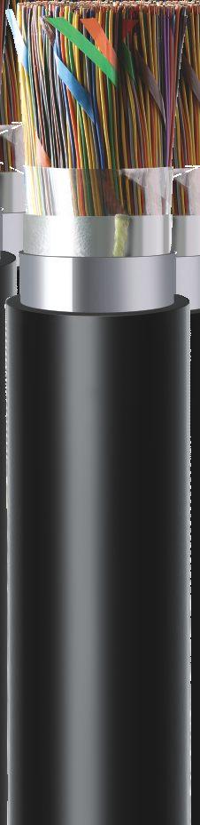
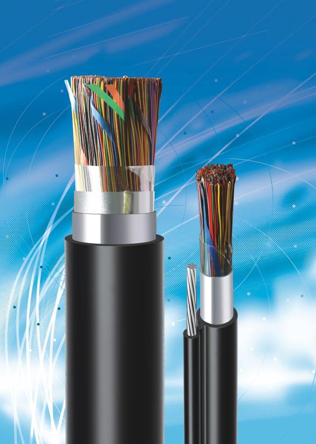
9 OUTDOOR CABLES CENTRAL-TUBE UNARMOURED CABLE (2-48 F) Water blocked Outdoor Underground Metro Suitable for Duct Installation For CATV application, aerial application along with messanger wire Typical Cross section of 48 Fibre Cable Construction Details Primary Coated Fibre Tube Filling Compound Loose Tube Strength member Rip Cords Outer Sheath Up to 48 enhance low water peak single mode fibres in full compliance with ITU-T-G.652.D (also available with G655 / G656 / G657 SM Fibre and OM1 / OM2 / OM3 & OM4 MM Fibre) Metallic, anti-buckling Steel rod as Strength Member. embedded in outer sheath (also available with non metallic strength member, FRP rod) Loose buffer tube fully filled and Centrally placed in the cable UV Stablized PE outer sheath, black (also available with HFFR / FR PVC) Technical Characteristics FIBRE DIAMETER WEIGHT TENSILE BENDING COUNT (mm) (Kg./Km) STRENGTH (N) RADIUS (mm) Nominal Nominal Installation Operating Temporary Permanent UPTO 12F F D 20D Installation TEMPERATURE RANGE (IEC F1) Operating -10 to +50 C -40 to +70 C 48F D 20D -10 to +50 C -40 to +70 C 15D 20D -10 to +50 C -40 to +70 C Color Coding - Fibre Blue Orange Green Brown Grey White Red Black Yellow Voilet Pink Aqua * For Fibre count more than 12F, bundles in multiple of 12F will be formed with color identification binder (Blue, Orange, Green & Brown) Special Features Lighter weight cable for faster and easier installation Drum Length 2000/ 3000/ 4000 meters ± 5% Mechanical Characteristics Repeated Bending (IEC E6) 30 Cycle, r= 20 X D, 5 Kg Load, D = Cable D Torsion Resistance (IEC E7) 10 Cycle (± 360 ) 5 Kg Weight, L= 2 Mtr Crush Resistance (IEC E3) 1000 N (100 X 100 mm) for 600 sec Impact Resistance (IEC E4) Height 100 mm, Weight = 5 Kg, 3 Nos Kink Resistance (IEC E10) 10 x D, D = Cable D Water Penetration (IEC F5B) 1 Mtr Water Head, 3 Meter Cable Sample, 24 Hours 10
10 OUTDOOR CABLES MULTI-TUBE SINGLE SHEATH UNARMOURED CABLE (2-144 F) Water blocked Outdoor Underground Metro Suitable for Duct Installation, pulled & blown Typical Cross section of 72 Fibre Cable Construction Details Primary Coated Fibre Tube Filling Compound Loose Tube(s) Central Strength Member Rip Cords Cable Filling Compound Peripheral Strength Member Core Wrapping Outer Sheath Up to 144 enhance low water peak single mode fibres in full compliance with ITU-T-G.652.D (also available with G655 / G656 / G657 SM Fibre and OM1 / OM2 / OM3 & OM4 MM Fibre) 2/4/6/8/12 fibre per tube combinations are available in 6/8/12 element construction Non metallic, anti-buckling FRP rod as Central Strength Member (also available with steel rod). Loose buffer tubes fully filled, S-Z Stranded Cable core fully filled with jelly ( also available in dry core) Glass yarn can be used as peripheral strength member S-Z core wrapped with polyester tape / water swellable tape Technical Characteristics UV Stablized PE outer sheath, black ( also available with FR PVC & HFFR FIBRE DIAMETER WEIGHT TENSILE BENDING COUNT (mm) (Kg./Km) STRENGTH (N) RADIUS (mm) Nominal Nominal Installation Operating Temporary Permanent UPTO 48F F D 20D Installation TEMPERATURE RANGE (IEC F1) Operating -10 to +50 C -40 to +70 C -10 to +50 C -40 to +70 C 96F D 20D -10 to +50 C -40 to +70 C 144F D 20D -10 to +50 C -40 to +70 C 15D 20D Color Coding - Fibre & Tube Blue Orange Green Brown Grey White Red Black Yellow Voilet Pink Aqua Special Features Single layer S-Z stranded construction Flexible buffer tubes provide easy fibre routing inside closure Light in weight, hence easy to install Drum Length 2000/ 3000/ 4000 meters ± 5% Mechanical Characteristics Repeated Bending (IEC E6) 30 Cycle, r= 20 X D, 5 Kg Load, D = Cable D Torsion Resistance (IEC E7) 10 Cycle (± 360 ) 5 Kg Weight, L= 2 Mtr Crush Resistance (IEC E3) 2000 N (100 X 100 mm) for 600 sec Impact Resistance (IEC E4) Height 500 mm, Weight = 5 Kg, 3 Nos Kink Resistance (IEC E10) 10 x D, D = Cable D Water Penetration (IEC F5B) 1 Mtr Water Head, 3 Meter Cable Sample, 24 Hours 11
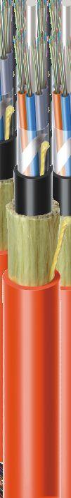
11 OUTDOOR CABLES MULTI-TUBE DOUBLE SHEATH UNARMOURED CABLE (2-144 F) Water blocked Outdoor Underground Metro Suitable for Duct Installation, pulled & blown Typical Cross section of Fibre Cable Construction Details Primary Coated Fibre Tube Filling Compound Loose Tube(s) Central Strength Member Rip Cords Cable Filling Compound Peripheral strength member Core Wrapping Inner Sheath, PE Outer Sheath, PA-12 Up to 144 enhance low water peak single mode fibres in full compliance with ITU-T-G.652.D (also available with G655 / G656 / G657 SM Fibre and OM1 / OM2 / OM3 & OM4 MM Fibre) 2/4/6/8/12 fibre per tube combinations are available in 6/8/12 element construction Non metallic anti-buckling FRP rod as Central Strength Member (also available with Steel rod) Loose buffer tubes fully filled, S-Z Stranded Cable core fully filled with jelly (also available in dry core) Glass yarn can be used as peripheral strength member S-Z core wrapped with polyester tape / water swellable tape UV Stablized HDPE inner sheath, Black Insect & termite resistant PA-12 outer sheath, Orange Technical Characteristics FIBRE DIAMETER WEIGHT TENSILE BENDING COUNT (mm) (Kg./Km) STRENGTH (N) RADIUS (mm) Nominal Nominal Installation Operating Temporary Permanent UPTO 48F F D 20D Installation TEMPERATURE RANGE (IEC F1) Operating -10 to +50 C -40 to +70 C -10 to +50 C -40 to +70 C 96F D 20D -10 to +50 C -40 to +70 C 144F D 20D -10 to +50 C -40 to +70 C 15D 20D Color Coding - Fibre & Tube Blue Orange Green Brown Grey White Red Black Yellow Voilet Pink Aqua Special Features Single layer S-Z stranded construction Flexible buffer tubes provide easy fibre routing inside closure Light in weight, hence easy to install Insect & termite resistant Drum Length 2000/ 3000/ 4000 meters ± 5% Mechanical Characteristics Repeated Bending (IEC E6) 30 Cycle, r= 20 X D, 5 Kg Load, D = Cable D Torsion Resistance (IEC E7) 10 Cycle (± 360 ) 5 Kg Weight, L= 2 Mtr Crush Resistance (IEC E3) 2500 N (100 X 100 mm) for 600 sec Impact Resistance (IEC E4) Height 500 mm, Weight = 5 Kg, 3 Nos Kink Resistance (IEC E10) 10 x D, D = Cable D Water Penetration (IEC F5B) 1 Mtr Water Head, 3 Meter Cable Sample, 24 Hours 12
12 OUTDOOR CABLES MULTI-TUBE DOUBLE LAYER UNARMOURED CABLE ( F) Water blocked Outdoor Underground Metro Suitable for Duct Installation, pulled & blown Typical Cross section of 240 Fibre Cable Construction Details Upto 288 enhance low water peak single mode fibers in full compliance with ITU-T-G.652.D Primary Coated Fibre Tube Filling Compound Loose Tube (s) Central Strength Member Core Wrapping over first layer of loose tube Peripheral strength member Core Wrapping over second layer of loose tube Rip cords Outer Sheath Non-metallic anti-buckling FRP rod as Central Strength Member. Loose buffer tubes fully filled, S-Z Stranded in two layers Cable core fully filled (also available in dry core) S-Z core wrapped with polyester tape / water swellable tape UV Stablized PE Outer sheath, black (also available with FR PVC & HFFR Technical Characteristics FIBRE DIAMETER WEIGHT TENSILE BENDING COUNT (mm) (Kg./Km) STRENGTH (N) RADIUS (mm) Nominal Nominal Installation Operating Temporary Permanent 192F D 20D 288F D 20D TEMPERATURE RANGE (IEC F1) Installation Operating -10 to +50 C -40 to +70 C -10 to +50 C -40 to +70 C Color Coding - Fibre Blue Orange Green Brown Grey White Red Black Yellow Voilet Pink Aqua * Tube coding: Blue (Marker), Orange(Tracer), remaining all natural Special Features Double layer S-Z stranded construction Flexible buffer tubes provide easy fibre routing inside closure Drum Length 2000/ 3000 meters ± 5% Mechanical Characteristics Repeated Bending (IEC E6) 30 Cycle, r= 20 X D, 5 Kg Load, D = Cable D Torsion Resistance (IEC E7) 10 Cycle (± 360 ) 5 Kg Weight, L= 2 Mtr Crush Resistance (IEC E3) 2000 N (100 X 100 mm) for 600 sec Impact Resistance (IEC E4) Kink Resistance (IEC E10) Water Penetration (IEC F5B) Height 500 mm, Weight = 5 Kg, 3 Nos 15 x D, D = Cable D 1 Mtr Water Head, 3 Meter Cable Sample, 24 Hours 13
13 OUTDOOR CABLES CENTRAL-TUBE ARMOURED CABLE (2-48F) Water blocked Rodent resistant Outdoor Underground Metro Impact resistant In areas where high mechanical load is required Suitable in area of rodent menace Direct burial & Inside duct - PE Outer Sheath Inside duct - FR PVC / HFFR / LSZH Outer Sheath Typical Cross section of 24 Fibre Cable Construction Details Primary Coated Fibre Tube Filling Compound Loose Tube Water Blocking Tape Armouring Rip Cords Strength Member Outer Sheath Up to 48 enhanced low water peak single mode fibres in full compliance with ITU-T-G.652.D (also available with G655 / G656 / G657 SM Fibre and OM1 / OM2 / OM3 & OM4 MM Fibre) Metallic anti-buckling steel rod as strength member. Embedded in outer sheath (also available with non metallic strength member FRP rod) Loose buffer tube fully filled and centrally placed in the cable Water blocking tape wrapping Electrolyte chrome plated, corrugated steel tape armoured UV Stablized PE Outer sheath, black (also available with FR PVC & HFFR Technical Characteristics FIBRE DIAMETER WEIGHT TENSILE BENDING COUNT (mm) (Kg./Km) STRENGTH (N) RADIUS (mm) Nominal Nominal Installation Operating Temporary Permanent 12F F D 20D Installation TEMPERATURE RANGE (IEC F1) Operating -10 to +50 C -40 to +70 C -10 to +50 C -40 to +70 C 48F D 20D -10 to +50 C -40 to +70 C 15D 20D Color Coding - Fibre Blue Orange Green Brown Grey White Red Black Yellow Voilet Pink Aqua * For Fibre count more than 12F, bundles in multiple of 12F will be formed with color identification binder (Blue, Orange, Green & Brown) Special Features Lighter weight cable for faster and easier installation Robust construction. Corrugated steel tape acts as protection against rodents and mechanical protection Drum Length 2000/ 3000/ 4000meters ± 5% Mechanical Characteristics Repeated Bending (IEC E6) 30 Cycle, r= 20 X D, 5 Kg Load, D = Cable D Torsion Resistance (IEC E7) 10 Cycle (± 360 ) 5 Kg Weight, L= 2 Mtr Crush Resistance (IEC E3) 2500 N (100 X 100 mm) for 600 sec Impact Resistance (IEC E4) Height 500 mm, Weight = 5 Kg, 3 Nos Kink Resistance (IEC E10) 10 x D, D = Cable D Water Penetration (IEC F5B) 1 Mtr Water Head, 3 Meter Cable Sample, 24 Hours 14
14 OUTDOOR CABLES MULTI-TUBE SINGLE SHEATH ARMOURED CABLE (2-144F) Water blocked Rodent resistant Outdoor Underground Metro Impact resistant In areas where high mechanical load is required Suitable in area of rodent menace Direct burial & Inside duct - PE Outer Sheath Inside duct - FR PVC / HFFR / LSZH Outer Sheath Typical Cross section of 72 Fibre Primary Coated Fibre Tube Filling Compound Loose Tube(s) Central Strength Member Cable Filling Compound Peripheral strength member Core Wrapping Rip Cords Water blocking media under armour Armouring Outer Sheath Cable Construction Details Up to 144 enhance low water peak single mode fibres in full compliance with ITU-T-G.652.D (also available with G655 / G656 / G657 SM Fibre and OM1 / OM2 / OM3 & OM4 MM Fibre) 2/4/6/8/12 fibre per tube combinations are available in 6/8/12 element construction Non metallic anti-buckling FRP rod as Central Strength Member. (also available with metallic strength member) Loose buffer tubes fully filled, S-Z Stranded Cable core fully filled with Thixotropic jelly (also available in dry core design) Glass yarn can be used as peripheral strength member Cable core is wrapped with polyester tape & water swellable tape Electrolytic chrome plated & Corrugated steel tape armouring UV Stablized HDPE outer sheath, black (also available with FR PVC & HFFR) Technical Characteristics FIBRE DIAMETER WEIGHT TENSILE BENDING COUNT (mm) (Kg./Km) STRENGTH (N) RADIUS (mm) Nominal Nominal Installation Operating Temporary Permanent UPTO 48F F D 20D Installation TEMPERATURE RANGE (IEC F1) Operating -10 to +50 C -40 to +70 C -10 to +50 C -40 to +70 C 96F D 20D -10 to +50 C -40 to +70 C 144F D 20D -10 to +50 C -40 to +70 C Color Coding - Fibre & Tube 15D 20D Blue Orange Green Brown Grey White Red Black Yellow Voilet Pink Aqua Special Features Single layer S-Z stranded construction Corrugated steel tape acts as protection against rodents and mechanical damage. Robust construction Flexible buffer tubes provide easy fibre routing inside closure Drum Length 2000/ 3000/ 4000meters ± 5% Mechanical Characteristics Repeated Bending (IEC E6) 30 Cycle, r= 20 X D, 5 Kg Load, D = Cable D Torsion Resistance (IEC E7) 10 Cycle (± 360 ) 5 Kg Weight, L= 2 Mtr Crush Resistance (IEC E3) 3000 N (100 X 100 mm) for 600 sec Impact Resistance (IEC E4) Height 500 mm, Weight = 5 Kg, 3 Nos Kink Resistance (IEC E10) 10 x D, D = Cable D Water Penetration (IEC F5B) 1 Mtr Water Head, 3 Meter Cable Sample, 24 Hours 15
15 OUTDOOR CABLES MULTI-TUBE DOUBLE SHEATH, ARMOURED CABLE (2-144 F) Water blocked Rodent resistant Outdoor Underground Metro Impact resistant In areas where high mechanical load is required Suitable in area of rodent menace Direct burial & Inside duct - PE Outer Sheath Inside duct - FR PVC / HFFR / LSZH Outer Sheath Typical Cross section of 72 Fibre Primary Coated Fibre Tube Filling Compound Loose Tube(s) Central Strength Member Cable Filling Compound Peripheral strength member Core Wrapping Inner Sheath Rip Cords Steel tape armouring Outer Sheath Cable Construction Details Up to 144 enhance low water peak single mode fibres in full compliance with ITU-T-G.652.D (also available with G655 / G656 / G657 SM Fibre and OM1 / OM2 / OM3 & OM4 MM Fibre) 2/4/6/8/12 fibre per tube combinations are available in 6/8/12 element construction Non metallic anti-buckling FRP rod as Central Strength Member (also available with metallic strength member) Loose buffer tubes fully filled, S-Z Stranded Cable core fully filled with jelly (also available in dry core design) Glass yarn can be used as peripheral strength member S-Z core wrapped with polyester tape /water swellable tape Electrolytic chrome plated & Corrugated steel tape armouring UV Stablized HDPE outer sheath, black (also available with FR PVC & HFFR) Technical Characteristics FIBRE DIAMETER WEIGHT TENSILE BENDING COUNT (mm) (Kg./Km) STRENGTH (N) RADIUS (mm) Nominal Nominal Installation Operating Temporary Permanent UPTO 48F F D 20D Installation TEMPERATURE RANGE (IEC F1) Operating -10 to +50 C -40 to +70 C -10 to +50 C -40 to +70 C 96F D 20D -10 to +50 C -40 to +70 C 144F D 20D -10 to +50 C -40 to +70 C Color Coding - Fibre & Tube 15D 20D Blue Orange Green Brown Grey White Red Black Yellow Voilet Pink Aqua Special Features Single layer S-Z stranded construction Corrugated steel tape acts as protection against rodents and mechanical damage. Robust construction Flexible buffer tubes provide easy fibre routing inside closure Drum Length 2000/ 3000/ 4000meters ± 5% Mechanical Characteristics Repeated Bending (IEC E6) 30 Cycle, r= 20 X D, 10 Kg Load, D = Cable D Torsion Resistance (IEC E7) 10 Cycle (± 360 ) 10 Kg Weight, L= 2 Mtr Crush Resistance (IEC E3) 4000 N (100 X 100 mm) for 600 sec Impact Resistance (IEC E4) Height 500 mm, Weight = 5 Kg, 10 Nos Kink Resistance (IEC E10) 10 x D, D = Cable D Water Penetration (IEC F5B) 1 Mtr Water Head, 3 Meter Cable Sample, 24 Hours 16

 2/4/6/8/12 fibre per tube combinations are available in 6/8/12 element construction Non-metallic and")
16 Outdoor Cables DIELECTRIC RODENT PROTECTED CABLE (2-144 F) Water blocked Outdoor Underground Metro Rodent resistant Direct burial / Inside Duct In areas with particularly high mechanical loads In areas with rodents Typical Cross Section of 72F Primary Coated Fibre Jelly filled Loose Tube Central Strength member Cable Filling Compound Polyester Tape Inner Sheath Non Metallic Armour Rip Cords Outer Sheath MULTI TUBE DESIGN Cable Construction Details Upto 144 enhance low water peak single mode fibers in full compliance with ITU-T-G.652.D (also available with G655 / G656 / G657 SM Fibre and OM1 / OM2 / OM3 & OM4 MM Fibre) 2/4/6/8/12 fibre per tube combinations are available in 6/8/12 element construction Non-metallic and anti-buckling element FRP rod used as Central Strength Member. Loose buffer tubes fully filled Thixotropic Jelly Loose buffer tubes S-Z Stranded Cable core is fully filled with Thixotropic Jelly (also available in dry core design) Cable core is wrapped with Polyester Tape / Water swellable tape UV Stabilized PE inner sheath, Black Glass Yarns used as dielectric armour UV Stabilized PE outer sheath, Black FIBRE DIAMETER WEIGHT TENSILE BENDING COUNT (mm) (Kg./Km) STRENGTH (N) RADIUS (mm) Nominal Nominal Installation Operating Temporary Permanent UPTO 48F F D 20D to +50 C to +70 C 96F D 20D to +50 C to +70 C 144F D 20D to +50 C to +70 C 15D 20D Installation TEMPERATURE RANGE (IEC F1) Operating to +50 C to +70 C Color Coding - Fibre & Tube Blue Orange Green Brown Grey White Red Black Yellow Voilet Pink Aqua Special Features Single layer stranded construction Particularly robust cable Flexible buffer tubes provide easy fibre routing inside closure All dielectric armoured Mechanical Characteristics Repeated Bending (IEC E6) 30 Cycle, r= 20 X D, 10 Kg Load, D = Cable D Torsion Resistance (IEC E7) 10 Cycle (± 360 ) 10 Kg Weight, L= 2 Mtr Crush Resistance (IEC E3) 2500 N (100 X 100 mm) for 600 sec Impact Resistance (IEC E4) Height 500 mm, Weight = 5 Kg, 3 Nos Kink Resistance (IEC E10) 10 x D, D = Cable D Water Penetration (IEC F5B) 1 Mtr Water Head, 3 Meter Cable Sample, 24 Hours 17


17 OUTDOOR CABLES MULTI-TUBE STEEL WIRE ARMOURED CABLE (2-144 F) Water blocked Rodent resistant Outdoor Underground Metro Impact resistant In areas where high pulling force is required In areas where complex cable run is required Direct burial & Inside duct - PE Outer Sheath Inside duct - FR PVC / HFFR / LSZH Outer Sheath Typical Cross section of 48 Fibre Technical Characteristics Primary Coated Fibre Tube Filling Compound Loose Tube(s) Central Strength Member Cabling Filling Compound Rip Cord Filler Core Wrapping over S-Z core Moisture Barrier Inner Sheath Armouring Core Wrapping over steel wire armour Outer Sheath Cable Construction Details Up to 144 enhance low water peak single mode fibres in full compliance with ITU-T-G.652.D (also available with G655 / G656 / G657 SM Fibre and OM1 / OM2 / OM3 & OM4 MM Fibre) Phosphate coated metallic anti-buckling steel rod as central strength member (also available with non metallic strength member, FRP rod) 2/4/6/8/12 fibre per tube combinations are available in 5/6/8/12 element constructions Loose buffer tubes fully filled S-Z Stranded Cable core fully filled with jelly PE coated Aluminium foil as moisture barrier UV Stablized PE inner sheath, black Galvanised Steel wire armour, wrapped with polyester tape UV stabilized HDPE outer sheath, black (also available with FR PVC & HFFR) FIBRE DIAMETER WEIGHT TENSILE BENDING COUNT (mm) (Kg./Km) STRENGTH (N) RADIUS (mm) Nominal Nominal Installation Operating Temporary Permanent UPTO 60F F D 20D Installation TEMPERATURE RANGE (IEC F1) Operating -10 to +50 C -40 to +70 C -10 to +50 C -40 to +70 C 96F D 20D -10 to +50 C -40 to +70 C 144F D 20D -10 to +50 C to +70 C Color Coding - Fibre & Tube 15D 20D Blue Orange Green Brown Grey White Red Black Yellow Voilet Pink Aqua Special Features Single layer S-Z stranded construction. Phosphate coating over steel wire CSM prevent Hydrogen generation. Aluminium Foils provides excellent protection against Moisture. Rugged & robust design Drum Length 2000 meters ± 5% Mechanical Characteristics Repeated Bending (IEC E6) Crush Resistance (IEC E3) Impact Resistance (IEC E4) 30 Cycle, 20 X D, 10 Kg Load, D = Cable D 6000 N (100 X 100 mm) for 600 sec Height 500 mm, Weight = 5 Kg, 10 Nos at Different Place Kink Resistance (IEC E10) 20 x D, D = Cable D Water Penetration (IEC F5) 1 Mtr Water Head, 3 Meter Cable Sample, 24 Hours 18
18 OUTDOOR CABLES MULTI-TUBE FRP ROD ARMOURED CABLE (2-144 F) Water blocked Rodent resistant Outdoor Underground Metro Impact resistant In areas where high pulling force is required In areas where complex cable run is required Direct burial & Inside duct - PE Outer Sheath Inside duct - FR PVC / HFFR / LSZH Outer Sheath Typical Cross section of 72 Fibre Primary Coated Fibre Tube Filling Compound Loose Tube(s) Central Strength Member Cabling Filling Compound Core Wrapping over S-Z core Inner Sheath Arrmouring Core Wrapping over FRP Rod armour Outer Sheath Cable Construction Details Up to 144 enhance low water peak single mode fibres in full compliance with ITU-T-G.652.D (also available with G655 / G656 / G657 SM Fibre and OM1 / OM2 / OM3 & OM4 MM Fibre) 2/4/6/8/12 fibre per tube combinations are available in 6/8/12 element construction Non-metallic anti-buckling FRP rod as Central Strength Member. Loose buffer tubes fully filled, S-Z Stranded Cable core is fully filled with Thixotropic Jelly (also available in dry core design) Cable core is wrapped with Polyester Tape and water swellable tape UV Stablized PE inner sheath, black FRP rods for armouring UV stabilized PE outer sheath, black (also available with FR PVC & HFFR) Technical Characteristics FIBRE DIAMETER WEIGHT TENSILE BENDING COUNT (mm) (Kg./Km) STRENGTH (N) RADIUS (mm) Nominal Nominal Installation Operating Temporary Permanent UPTO 48F F D 20D Installation TEMPERATURE RANGE (IEC F1) Operating -10 to +50 C -40 to +70 C -10 to +50 C -40 to +70 C 96F D 20D -10 to +50 C -40 to +70 C 144F D 20D -10 to +50 C -40 to +70 C Color Coding - Fibre & Tube 15D 20D Blue Orange Green Brown Grey White Red Black Yellow Voilet Pink Aqua Special Features Single layer S-Z stranded construction. Completely dielectric construction Rugged & robust design Drum Length 2000/ 3000/ 4000 meters ± 5% Mechanical Characteristics Repeated Bending (IEC E6) 30 Cycle, 20 X D, 10 Kg Load, D = Cable D Torsion Resistance (IEC E7) 10 Cycle (± 360 ) 5 Kg Weight, L= 2 Mtr Crush Resistance (IEC E3) 3000 N (100 X 100 mm) for 600 sec Impact Resistance (IEC E4) Height 500 mm, Weight = 5 Kg, 10 Nos at Different Place Kink Resistance (IEC E10) 20 x D, D = Cable D Water Penetration (IEC F5) 1 Mtr Water Head, 3 Meter Cable Sample, 24 Hours 19
19 OUTDOOR CABLES MULTI-TUBE RIBBON TYPE CABLE ( F) Water blocked Rodent resistant Outdoor Underground Metro Suitable for Duct Installation, pulled & blown Typical Cross section of 288 Fibre Primary Coated Optical Fibre Ribbon Tube Filling Compound Loose Tubes Central Strength Member Cabling Filling Compound Filler Core Wrapping Inner Sheath Outer Sheath Cable Construction Details Up to 576 enhance low water peak single mode fibres in full compliance with ITU-T-G.652.D in 4/8/12 Fibre Ribbon (also available with G655 / G656 / G657 SM Fibre and OM1 / OM2 / OM3 & OM4 MM Fibre) Non metallic and anti-buckling FRP rod as Central Strength Member Loose buffer tubes fully filled, S-Z Stranded Cable core is fully filled with Thixotropic Jelly (also available in dry core design) S-Z core wrapped with polyester tape/water swellable tape UV Stablized PE Inner sheath, Black Insect & termite resistance PA-12 outer sheath, Orange Technical Characteristics FIBRE DIAMETER WEIGHT TENSILE BENDING COUNT (mm) (Kg./Km) STRENGTH (N) RADIUS (mm) Nominal Nominal Installation Operating Temporary Permanent UPTO 96F F D 20D Installation TEMPERATURE RANGE (IEC F1) Operating -10 to +50 C -40 to +70 C -10 to +50 C -40 to +70 C 288F D 20D -10 to +50 C -40 to +70 C 576F D 20D -10 to +50 C -40 to +70 C Color Coding - Fibre & Tube 15D 20D Blue Orange Green Brown Grey White Red Black Yellow Voilet Pink Aqua * Identification of ribbon in loose tube - 1 ribbon 1, 2 ribbon 2, 3 ribbon 3... Special Features Single layer S-Z stranded construction Flexible buffer tubes provide easy fibre routing inside closure Insect & Termite resistant Drum Length 2000/ 3000/ 4000 meters ± 5% Mechanical Characteristics Repeated Bending (IEC E6) 30 Cycle, r= 20 X D, 10 Kg Load, D = Cable D Torsion Resistance (IEC E7) 10 Cycle (± 360 ) 10 Kg Weight, L= 2 Mtr Crush Resistance (IEC E3) 2500 N (100 X 100 mm) for 600 sec Impact Resistance (IEC E4) Height 500 mm, Weight = 5 Kg, 3 Nos Kink Resistance (IEC E10) 10 x D, D = Cable D Water Penetration (IEC F5B) 1 Mtr Water Head, 3 Meter Cable Sample, 24 Hours 20
20 OUTDOOR CABLES ALL DI-ELECTRIC SELF SUPPORTING AERIAL CABLE (2-144 F) Water blocked Aerial Outdoor Shotgun resistant Track resistant (25 kv) Suitable for self supporting aerial installation with rigorous load conditions, including heavy wind and ice Suitable for span length of 100 mtrs (also available for other span length) Typical Cross section of 72 Fibre Cable Construction Details Primary Coated Fibre Tube Filling Compound Loose Tube(s) Cable filling compound Central Strength Member Core Wrapping Inner Sheath Peripheral strength member Outer Sheath Up to 144 enhance low water peak single mode fibres in full compliance with ITU-T-G.652.D (also available with G655 / G656 / G657 SM Fibre and OM1 / OM2 / OM3 & OM4 MM Fibre) Non metallic anti-buckling FRP rod as Central Strength Member Loose buffer tubes fully filled, S-Z Stranded Cable core fully filled (also available in dry core design) Cable core is wrapped with Polyester Tape/water swellable tape UV Stablized PE inner sheath, Black High modulus, Aramid yarn peripheral strength member UV Stablized PE Outer sheath, Orange Technical Characteristics FIBRE DIAMETER WEIGHT TENSILE BENDING COUNT (mm) (Kg./Km) STRENGTH (N) RADIUS (mm) Nominal Nominal Installation Operating Temporary Permanent UPTO 48F UPTO 72F D 20D Installation TEMPERATURE RANGE (IEC F1) Operating -10 to +50 C -40 to +70 C -10 to +50 C -40 to +70 C 96F D 20D -10 to +50 C -40 to +70 C 144F D 20D -10 to +50 C -40 to +70 C Color Coding - Fibre & Tube 15D 20D Blue Orange Green Brown Grey White Red Black Yellow Voilet Pink Aqua Special Features Single layer S-Z stranded construction Offers exceptional strength and corrosion resistance for aerial application Flexible buffer tubes provide easy fibre routing inside closure Drum Length 2000/ 3000/ 4000 meters ± 5% Mechanical Characteristics Repeated Bending (IEC E6) 30 Cycle, 20 X D, 5 Kg Load, D = Cable D Torsion Resistance (IEC E7) 10 Cycle (± 180 ) 5 Kg Weight, L= 2 Mtr Crush Resistance (IEC E3) 3000 N (100 X 100 mm) for 600 sec Impact Resistance (IEC E4) Height 500 mm, Weight = 5 Kg, 3 Nos Kink Resistance (IEC E10) 20 x D, D = Cable D Water Penetration (IEC F5) 1 Mtr Water Head, 3 Meter Cable Sample, 24 Hours 21
21 OUTDOOR CABLES SINGLE-TUBE FIGURE-8 TYPE AERIAL CABLE (2-24 F) Water blocked Aerial Outdoor Lashed aerial installation with rigorous load conditions, including heavy wind and ice Suitable for span length of 100 mtrs Typical Cross section of 12 Fibre Messenger wire Outer Sheath over messenger wire Primary Coated Fibre Tube Filling Compound Loose Tube Outer Sheath Cable Construction Details Upto 48F enhance low water peak single mode fibers in full compliance with ITU-T-G.652.D (also available with G655 / G656 / G657 SM Fibre and OM1 / OM2 / OM3 & OM4 MM Fibre) Loose buffer tubes fully filled High tensile, galvanised, stranded steel wire used as integrated messenger wire UV Stablized PE outer sheath, black Technical Characteristics FIBRE DIAMETER WEIGHT TENSILE BENDING COUNT (mm) (Kg./Km) STRENGTH (N) RADIUS (mm) Nominal Nominal Installation Operating Temporary Permanent UPTO 12F 6.5x Installation TEMPERATURE RANGE (IEC F1) Operating -10 to +50 C -40 to +70 C 16/24F 7.5x D 20D -10 to +50 C -40 to +70 C 48F 10.0x D 20D -10 to +50 C -40 to +70 C 15D 20D Color Coding - Fibre & Tube Blue Orange Green Brown Grey White Red Black Yellow Voilet Pink Aqua * For Fibre count more than 12F, bundles in multiple of 12F will be formed with color identification binder (Blue, Orange, Green & Brown) Special Features Central Loose tube construction Offers exceptional strength and corrosion resistance for aerial application Integrated High tensile messenger for superior strength and corrosion resistance. Drum Length 2000/ 3000/ 4000 meters ± 5% Mechanical Characteristics Repeated Bending (IEC E6) 30 Cycle, 20 X D, 10 Kg Load, D = Cable D Torsion Resistance (IEC E7) 10 Cycle (± 180 ) 5 Kg Weight, L= 2 Mtr Crush Resistance (IEC E3) 1000 N (100 X 100 mm) for 600 sec Impact Resistance (IEC E4) Height 500 mm, Weight = 5 Kg, 3 Nos Kink Resistance (IEC E10) 20 x D, D = Cable D Water Penetration (IEC F5) 1 Mtr Water Head, 3 Meter Cable Sample, 24 Hours 22
22 OUTDOOR CABLES MULTI-TUBE FIGURE-8 TYPE AERIAL CABLE (2-144 F) Water blocked Aerial Outdoor Lashed aerial installation with rigorous load conditions, including heavy wind and ice Suitable for span length of 100 mtrs Typical Cross section of 72 Fibre Messenger wire Outer Sheath over messenger wire Primary Coated Fibre Tube Filling Compound Loose Tube(s) Cable Filling compound Central Strength Member Core Wrapping Outer Sheath Cable Construction Details Upto 144 enhance low water peak single mode fibers in full compliance with ITU-T-G.652.D (also available with G655 / G656 / G657 SM Fibre and OM1 / OM2 / OM3 & OM4 MM Fibre) 2/4/6/8/12 fibre per tube combinations are available in 6/8/12 element construction Non-metallic anti-buckling FRP rod as Central Strength Member. Loose buffer tubes fully filled, S-Z Stranded Cable core fully filled (also available in dry core) S-Z core wrapped with polyester tape / water swelleble tape UV Stablized PE outer sheath, black High tensile, galvanised, stranded steel wire used as integrated messenger wire Technical Characteristics FIBRE DIAMETER WEIGHT TENSILE BENDING TEMPERATURE RANGE COUNT (mm) (Kg./Km) STRENGTH (N) RADIUS (mm) (IEC F1) Nominal Nominal Installation Operating Temporary Permanent Installation Operating UPTO 72F 10.6/ D 20D -100 to +500 C -400 to +700 C 96F 12.3/ D 20D -100 to +500 C -400 to +700 C 144F 14.7/ D 20D -100 to +500 C -400 to +700 C Color Coding - Fibre & Tube Blue Orange Green Brown Grey White Red Black Yellow Voilet Pink Aqua Special Features Single layer S-Z stranded construction Offers exceptional strength and corrosion resistance for aerial application Integrated High tensile messenger for superior strength and corrosion resistance. Flexible buffer tubes provide easy fibre routing inside closure Drum Length 2000/ 3000/ 4000 meters ± 5% Mechanical Characteristics Repeated Bending (IEC E6) 30 Cycle, 20 X D, 5 Kg Load, D = Cable D Torsion Resistance (IEC E7) 10 Cycle (± 180 ) 5 Kg Weight, L= 2 Mtr Crush Resistance (IEC E3) 2000 N (100 X 100 mm) for 600 sec Impact Resistance (IEC E4) Height 500 mm, Weight = 5 Kg, 3 Nos Kink Resistance (IEC E10) 20 x D, D = Cable D Water Penetration (IEC F5) 1 Mtr Water Head, 3 Meter Cable Sample, 24 Hours 23
23 OUTDOOR CABLES HYBRID (OPTICAL & COPPER) Water blocked Outdoor Aerial Metro Suitable for Under Ground Armoured Cable Upto 24F Axle Counting Signaling Typical Cross section of Hybrid Cable Outer Sheath Galvanised Steel Tape Armouring Inter Mediate Sheath Aluminium Wire Screening Inner Sheath, PE Core Filling Compound Core Wrapping Aluminium Foil Jelly Filled Loose tube with Fibre 0.9 mm Copper Quad Central Strength Member (Upcoated FRP) Cable Construction Details Central Strength Member Loose tube No. of Quads Core wrapping Moisture Barrier Inner Sheath Screening Tape Intermediate Sheath Armouring Outer Sheath Upcoated Fibre Reinforced Plastic-FRP (Non metallic) 2 No. PBT Loose tube filled with Thixotropic Jelly 6 Quads with Identification binders Polyester Tape applied helically Aluminium Foil PE Inner Sheath Aluminium wire screening Barrium Chromate Tape PE Intermediate Sheath Double Steel tape armouring PE Outer Sheath Color Coding - Fibre & Tube Blue Orange Green Brown Grey White Red Black Yellow Voilet Pink Aqua Special Features Suitable for underground installation on pathways or roads Rodent & Termite proof. Robust under all conditions of operation, adjustment, replacement, storage and transport. Suitable for lightning prone areas. Better tensile strength. Drum Length 1000 meters ± 5% Mechanical Characteristics Tensile strength Cable Bend Test Repeated Bending test Torsion Test Crush Resistance Impact Test Kink Test Operating Temp. Water Penetration Test : 5000 N : 20D : 5 kg, 30 Cycles : 400 N : 4000 N, 600 Sec : 50 N, 10 Impact : 20 D 0 0 : -20 C to +70 C : 3mtrs sample, 1mtr Height Physical Characteristics Cable Outer Diameter Nominal Cable Weight Color Coding for Quad : : mm : 1500 Kg/KM No1 - White, Orange, Red, Green No3 - White, Brown, Red, Green No5 - White, Yellow, Red, Green No2 - White, Blue, Red, Green No4 - White, Green, Red, Green No6 - White, Black, Red, Green 24
24 FTTH CABLES DROP CABLE (1/2 F) Outdoor Aerial Metro Drop Cable suitable for aerial application. Typical Cross section of 2 Fibre Fibre (250 µm) Strength Member Sheath Cable Construction Details Up to 2 enhance low water peak single mode fibres in full compliance with ITU-T-G.652.D (also available with G657 SM Fibre and OM1 / OM2 / OM3 & OM4 MM Fibre) FRP / ARP rod as strength member Steel wire as integrated messenger wire LSZH shealth Outer Sheath over messenger wire Messenger Wire Technical Characteristics FIBRE DIAMETER WEIGHT TENSILE BENDING COUNT (mm) (Kg./Km) STRENGTH (N) RADIUS (mm) Nominal Nominal Installation Operating Temporary Permanent Installation TEMPERATURE RANGE (IEC F1) Operating 2F 2.0 X to +70 C -40 to +70 C Color Coding - Fibre Blue Orange Special Features Easy access to the fibres Quick Cable Entry & Easy-Peel Easy Seal in Closures Low insertion and back reflection loss Good durability High Return Loss High temperature stability Clean, Gel-Free, Dry Design Mechanical Characteristics Torsion Resistance (IEC E11) 50 N (± 180 ) 10 Cycles Impact Resistance (IEC E4) Height 1 mtr., Weight = 0.3 Kg, 3 Nos at different location Drum Length 500 meters ± 5% 25
25 FTTH / INDOOR CABLES INDOOR DROP CABLE (1/2 F) Flame resistant Indoor Metro Low bending Cable suitable for Indoor Application. Typical Cross section of 2 Fibre Cable Construction Fibre (250 µm) Strength Member Up to 2 enhance low water peak single mode fibres in full compliance with ITU-T-G.652.D (also available with G657 SM Fibre and OM1 / OM2 / OM3 & OM4 MM Fibre) FRP / ARP rod as strength member LSZH shealth Outer Sheath, LSZH TECHNICAL CHARACTERISTICS FIBRE DIAMETER WEIGHT TENSILE BENDING COUNT (mm) (Kg./Km) STRENGTH (N) RADIUS (mm) Nominal Nominal Installation Operating Temporary Permanent 2F 2.0 X Installation TEMPERATURE RANGE (IEC F1) Operating -20 to +70 C -40 to +70 C Color Coding - Fibre Blue Orange Special Features Easy access to the fibres Fast Installation Quick Cable Entry & Easy-Peel Easy Seal in Closures Maximization of Duct Space Flame Retardant Sheath Good durability Clean, Gel-Free, Dry Design Mechanical Characteristics Torsion Resistance (IEC E1) 40 N (± 180 ) 10 Cycles Impact Resistance (IEC E4) Height 1 mtr., Weight = 0.3 Kg, 3 Nos at different location Drum Length 500 meters ± 5% 26
26 FTTH Cables CENTRAL-TUBE AIRBLOWN MICRO CABLE (2-12F) Outdoor Metro Underground Inside building, suitable for Indoor use Typical Cross Section Of 4 F Air Blown Cable Jelly Filled Loose tube (Thixotropic Jelly) Fibers Strength Member Outer Sheath Cable Construction Details Up to 4 enhance low water peak single mode fibres in full compliance with ITU-T-G.652.D (also available with G655 / G656 / G657 SM Fibre) Loose buffer tube fully filled ARP/KRP/FRP rod as a strength member inside the loose tube Insect & Termite resistance PA-12 outer sheath, Orange Typical Cross Section Of 12f Unitube Micro Cable Jelly Filled Loose tube Fibers Aramid Yarn Outer Sheath Rip Cord Cable Construction Details (Available in 2.5mm & 3.8mm Dia) Up to 12 enhance low water peak single mode fibres in full compliance with ITU-T-G.652.D (also available with G655 / G656 / G657 SM Fibre) Loose buffer tubes fully filled Aramid yarns as flexible peripheral strength member Rip cords for ripping outer jacket Insect & Termite resistance PA-12 outer sheath, Orange Technical Characteristics-Air Blown & Unitube Micro Cable FIBRE DIAMETER WEIGHT TENSILE BENDING COUNT (mm) (Kg./Km) STRENGTH (N) RADIUS (mm) Nominal Nominal Installation Operating Temporary Permanent 2F D 20D Installation TEMPERATURE RANGE (IEC F1) RESISTANCE (N) Operating CRUSH (IEC E3) -20 to +50 C -40 to +70 C 100 N/(10x10cm) F D 20D -20 to +500 C -40 to +70 C 100 N/(10x10cm) UP TO 12F D 20D -20 to +500 C -40 to +70 C 500 N/(10x10cm) UP TO 12F D 20D -20 to +500 C -40 to +70 C 1000 N/(10x10cm) Color Coding - Fibre Blue Orange Green Brown Grey White Red Black Yellow Voilet Pink Aqua Special Features Completely dielectric cable / non metallic cable immune to electromagnetic interferences Suitable for Micro duct Installation Drum Length 2000/3000/4000 meters ± 5% Mechanical Characteristics Repeated Bending (IEC E6) 30 Cycle, 20 X D, 1 Kg Load, D = Cable Diameter Torsion Resistance (IEC E7) 2 Cycle (± 180 ) 1 Kg Weight, L= 2 Mtr Kink Resistance (IEC E10) 15 x D, D = Cable D 27
27 FTTH Cables MICRO CABLE Multitube Design (24-144F) Outdoor Metro Underground Suitable for installation in Micro Ducts Typical Cross Section of 48 F Cable Construction Outer Sheath Loose tube(s) Primary Coated Fibre Tube Filling Compound Central Strength Member Filler Rip Cord Upto 144 fibers in full compliance with ITU-T-G 652 D (also available with G655 / G656 / G657 SM Fibre and OM1 / OM2 / OM3 & OM4 MM Fibre) Non metallic, anti-buckling FRP rod as Central Strength Member (PE upcoated for 144 F) Loose buffer tubes fully filled, S-Z Stranded Rip cords for easy stripping Insect and Termite resistant PA-12 outer sheath, Orange (also available with PE outer sheath) Technical Characteristics FIBRE DIAMETER WEIGHT TENSILE BENDING COUNT (mm) (Kg./Km) STRENGTH (N) RADIUS (mm) Nominal Nominal Installation Operating Temporary Permanent Installation TEMPERATURE RANGE (IEC F1) Operating UPTO 72F D 20D -20 to +70 C -40 to +70 C 96F D 20D -20 to +70 C -40 to +70 C 144F D 20D -20 to +70 C -40 to +70 C Color Coding - Fibre & Tube Blue Orange Green Brown Grey White Red Black Yellow Voilet Pink Aqua Special Features Completely dielectric cable / non metallic cable immune to electromagnetic interferences High level bend capacity Low friction jacket design Easy access and breakout of Fibers Drum Length 2000/ 3000/ 4000 meters ± 5% Mechanical Characteristics Repeated Bending (IEC E6) 30 Cycle, 20 X D, 1 Kg Load, D = Cable Diameter Torsion Resistance (IEC E7) 2 Cycle (± 360 ) 5 Kg Weight, L= 2 Mtr Crush Resistance (IEC E3) 1000 N (100 X 100 mm) for 600 sec Kink Resistance (IEC E10) 15 x D, D = Cable D 28
28 FTTH / Indoor Cables INTERCONNECT CABLES Indoor Metro Flame resistant Communication racks and wiring closets, walls, ceilings, floor ducts, etc In the final connection to terminal devices such as workstation and computer terminals for high speed voice, video, data, and FTTx applications Short run office & computer room cabling Patch cords, Pigtails & Jumpers Typical Cross Section of Simplex Cable Construction Details - Simplex Aramid Yarn Tight Buffer (Nylon/LSZH) Primary Coated Fibre (G652D / G657A / OM1 / OM2 / OM3/ OM4) Outer Jacket, LSZH A single optical fibre is tight buffered and surrounded by aramid yarn strength member and jacketed with riser or plenum or LSZH grade jacketing to 2.0/3.0 mm diameter. Typical Cross Section of Duplex Cable Construction Details - Duplex Two Simplex cables 2.0/3.0 mm are joined as a figure-8 design Aramid Yarn Tight Buffer (Nylon/LSZH) Primary Coated Fibre (G652D / G657A / OM1 / OM2 / OM3/ OM4) Outer Jacket, LSZH Typical Cross Section of Flat Twin Cable Construction Details - Flat Twin Aramid Yarn Tight Buffer (Nylon/LSZH) Primary Coated Fibre (G652D / G657A / OM1 / OM2 / OM3/ OM4) Mini Cable Jacket Outer Jacket, LSZH Duplex Zip cable (2.0/3.0 mm) is jacketed with riser, plenum or LSZH grade jacketing. Drum Length 1000/ 2000 meters ± 5% 29
29 FTTH / Indoor Cables BREAKOUT TIGHT BUFFER UNARMOURED OPTICAL FIBRE CABLE (2-16F) Indoor Metro Flame resistant Rugged multi fibre cross connect Intra building backbone Fibre backbone to communication closets Typical Cross Section of 8F Cable Construction Details Simplex Subunits LSZH Sheath Water Swellable Tape Up coated FRP 4/6/8/12/16 Fibre of Single mode fibre in full compliance with ITU-T G652D (also available with G657 SM Fibre and OM1 / OM2 / OM3 & OM4 MM Fibre) FRP and Aramid Yarns as Strength Member PA-12 tight coating on Fibre LSZH Compound for sheathing for simplex subunits & outer sheath of cable FIBRE DIAMETER WEIGHT TENSILE BENDING COUNT (mm) (Kg./Km) STRENGTH (N) RADIUS (mm) Nominal Nominal Installation Operating Temporary Permanent 4F F F F F Installation TEMPERATURE RANGE (IEC F1) Operating 15D 20D to +70 C to +70 C D 20D to +70 C to +70 C D 20D to +70 C to +70 C D 20D to +70 C to +70 C D 20D to +70 C to +70 C Special Features Individual cores are printed at every 200 mm for identification Tight buffer & simplex jacket are available in variety of colours. Easy access to the fibres Quick Cable Entry Mechanical Characteristics Torsion Resistance (IEC E7) 2 Cycle (± 360 ) 1 Kg Weight, L= 2 Mtr Crush Resistance (IEC E3) 1000 N (100 X 100 mm) for 60 sec Kink Resistance (IEC E10) 15 x D, D = Cable D Drum Length 1000 meters ± 10% 30
30 FTTH / Indoor Cables FANOUT TIGHT BUFFER UNARMOURED OPTICAL FIBRE CABLE (2-48F) Indoor Metro Flame resistant Rugged multi fibre cross connect Intra building backbone Fibre backbone to communication closets Typical Cross Section of 2F Cable Construction Details 250 Micron Fibre Tight Buffer Aramid Yarn LSZH Sheath Upto 48 Fibre of Single mode fibre in full compliance with ITU-T G652D (also available with G657 SM Fibre and OM1 / OM2 / OM3 & OM4 MM Fibre) Aramid Yarns as Strength Member PA-12 / LSZH tight coating on Fibre LSZH Compound for outer sheathing FIBRE DIAMETER WEIGHT TENSILE BENDING COUNT (mm) (Kg./Km) STRENGTH (N) RADIUS (mm) Nominal Nominal Installation Operating Temporary Permanent UPTO 6F /12F Installation TEMPERATURE RANGE (IEC F1) Operating D 20D to +70 C to +70 C D 20D to +70 C to +70 C 36/48F D 20D to +70 C to +70 C Color Coding - Fibre Blue Orange Green Brown Grey White Red Black Yellow Voilet Pink Aqua * For Fibre count more than 12F, bundles in multiple of 9/12F will be formed with color identification binder (Blue, Orange, Green & Brown) Special Features Tight buffer & jacket are available in variety of colours. Easy access to the fibres Quick Cable Entry Mechanical Characteristics Torsion Resistance (IEC E7) 2 Cycle (± 360 ) 1 Kg Weight, L= 2 Mtr Crush Resistance (IEC E3) 1000 N (100 X 100 mm) for 600 sec Drum Length 1000 meters ± 10% 31
31
32
33 Outdoor Underground : Local distribution networks - Primary & Secondary Junction between exchanges Typical Cross section for Armoured Cable Cable Construction Details Conductor Conductor - Each conductor consists of a round wire of annealed high conductivity copper. Insulation Each conductor is insulated with Foam Skin / Solid PE insulation. Foam Skin insulation consists of an extruded inner layer of uncoloured foam, covered by an extruded outer layer of coloured skin with required colours to meet the specification. For Solid insulation each conductor is insulated with Solid medium/high density polyethylene insulation. Features: Armoured & Unarmoured construction Availability of standard conductor sizes ranging from 0.4 mm to 0.9 mm diameter. Available in sizes up to 2400 pairs Suitable for installation in ducts Direct Burial application for armoured cable Twinning Units & Super Units Stranding Filling Core Wrapping & Screening Two insulated conductors are twisted with uniform lay to form a pair. The length of the lay of the pairs is so choses that the cross talk is minimum. No's of twisted pairs are laid up to form a group which constitutes a unit. Twisted pairs/ super units are stranded to form a cable core. The cable core is fully filled with water resistant compound which is compatible with the polythene insulation of the conductors. The filled cable core is wrapped with at least one helical or longitudinal plastic tape. Thereafter one aluminium tape, coated with copolymer on both sides is applied longitudinally over the cable core with a specified overlap. Conductor Diameter 0.40 mm Mutual Capacitance Conductor Resistance Attenuation at at 20ºC (Solid or Foam 150KHz. Skin Cable) 135 ± 8 O /Km db/km (max.avg.) 0.50 mm 86 ± 6 O /Km 8.25 db/km (max. avg.) 0.63 mm 58 ± 4 O /Km 6.30 db/km (max. avg.) 0.90 mm 28 ± 2 O /Km 4.40 db/km (max. avg.) Capacitance Unbalance 52 +/- 3 nf/km (avg.) Pair to Pair Pair to Earth 52 +/- 4.5 nf/km 50 pf/km (Max. Avg.) 750 pf/km (max. avg.) (individual) 200 pf/km (Max.) 3000 pf/km (max.) Sheathing The screened cable core is sheathed with black polythene compound grade 03C as per BS:6234. Bedding tape If the cable is required to be armoured, two helical lapping of polythene bedding tape is applied over the polythene sheath. Armouring Jacketing The cable is then armoured with two applications of galvanized steel tape each applied helically with a specified gap. The second tape covers the gap left by the first tape. The armoured cable is finally jacketed with black polythene compound grade 03C of BS:6234. Insulation Resistance : 5000 mega ohms / Km (Min.) ELFEXT :55 db/km NEXT : 55 db (min.) at 150 KHz. (min) at 150 KHz 67.8 db/km (RMS) at 150 KHz.

34 OUTDOOR CABLES SELF SUPPORTING AERIAL (FIGURE 8 TYPE) TELEPHONE CABLE Outdoor Aerial : Suitable for Aerial Installation Local distribution networks - Secondary networks Typical Cross section for Armoured Cable Construction Features: Availability of standard conductor sizes of 0.4, 0.5, 0.6 & 0.9mm diameter Figure-8 construction Availability upto 200 pairs GI Wire Strand Outer Sheath (LDPE) Moisture Barrier Copper Conductors Coloured Solid PE Insulation PETP Tape Suitable for installation in Hilly areas/areas where digging is not possible Conductor Insulation Twinning Units & Super Units Stranding Each conductor consists of a round wire of annealed high conductivity copper. Each conductor is insulated with solid medium/high density polyethylene insulation. Two insulated conductors are twisted with uniform lay to form a pair. The length of the lay of the pairs is so chosen that the cross-talk is minimum. 10 or 20 No's of twisted pairs are laid up to form a group which constitutes a unit. Each unit should have an overlapping for color ID. In case of cables having more than 100 pairs, 5 units of 10 pairs or 20 pairs are laid up to constitute 50 or 100 pairs of super units respectively. For cable upto 20 pairs the required number of twisted pairs are stranded to form a cable core. For cables having 50 and 100 pairs, 5 numbers of 10 pair or 20 pair units are stranded to form 50 and 100 pair cables respectively. For cables having higher than 100 pairs, required number of super units are stranded to form a cable core. Technical Details Conductor Conductor Resistance Attenuation Diameter at 20ºC (Solid or Foam at 105KHz. Skin Cable) 0.40 mm 135 ± 8 O /Km db/km (max.avg.) 0.50 mm 86 ± 6 O /Km 8.25 db/km (max. avg.) 0.63 mm 58 ± 4 O /Km 6.30 db/km (max. avg.) 0.90 mm 28 ± 2 O /Km 4.40 db/km (max. avg.) Mutual Capacitance Capacitance Unbalance 52 ± 3 nf/km (avg.) Pair to Pair Pair to Earth 52 ± 4.5 nf/km 50 pf/km (Max. Avg.) 750 pf/km (max. avg.) (individual) 200 pf/km (Max.) 3000 pf/km (max.) Core The cable core is wrapped with at least one helical Wrapping or longitudional plastic tape. Thereafter one & Screening aluminium tape,coated with co-polymer on both sides is applied longitudinally over the cable core with a specified overlap. The tape is sealed and bonded to the inner surface of the polythene sheath. Suspension A Suspension Wire / Strand is provided. Wire / Strand Sheathing The screened cable core along with suspension wire as an integral part with the cable is sheathed with black polythene compound to form figure-8 Insulation Resistance : 2500 mega ohms / Km (Min). ELXT : 55 db/km (min)at 150 KHz 67.8 db/km (RMS) at 150 KHz. NEXT : 55 db (min.) at 150 Khz. 35
35 OUTDOOR CABLES UNDERGROUND JELLY FILLED QUAD CABLES Outdoor Underground Axle counter Signalling Typical Cross section for Armoured Cable Technical Details Conductor Conductor Resistance Attenuation at 20ºC Diameter at 20ºC 0.90mm 28 (Each Core) /Km (Max) 56 (loop) /Km (Max) 2 db/km (Max. Avg.)at Hz 1.4mm 11.6 (Each Core) 0.3 db/km (Max. Avg.) at 0.8KHz /Km (Max) 0.8 db/km (Max. Avg.) at 5KHz 23.2 (loop) 1.3 db/km (Max. Avg.) at 21KHz /Km (Max) 2.5 db/km (Max. Avg.) at 150KHz Mutual Capacitanc 50 ± 2.5 nf/ Km (avg.) Pair to Pair Pair to Earth 50 ±6 nf/km (individual) 300 pf/km (max.) 1500 pf/km (max. avg. Insulation Resistance 5000 mega s / Km (min.) 0.90 mm ELFEXT : 150 KHz NEXT : 55 db (min.) at 150 KHz 55 db/km Ind. (Min.) 67.8 db/km (RMS) (Min.) 1.4 mm ELFEXT : at 0.8KHz, 5KHz NEXT : 55 db (min.) at 0.8 KHz, 21 KHz & 150 KHz 5 KHz, 21 KHz & 150 KHz 60.0 db/km Ind. (Min.) 70.8 db/km (RMS) (Min.) Reduction Factor ( Field intensity of 50v to 450v) : 0.10 (Max) Characteristic Impedance ( ) 0.90 mm 470 +/- 15% at 0.8KHz 195 +/- 15% at 5.0 KHz 1.4 mm 310 +/- 15% at 0.8KHz 150 +/- 15% at 5.0 KHz 110 +/- 15% at 21.0 KHz 100 +/- 15% at KHz Color Coding for Quad : No1 - White, Orange, Red, Green No3 - White, Brown, Red, Green No5 - White, Yellow, Red, Green Insulated Copper Conductor Core Filling Compound Core Wrapping Flooding Compound Moisture Barrier Inner Sheath Screening & Protection Intermediate Sheath Armour Jacketing Filler 4.40 db/km (Max. Avg.) at 150KHz Capacitance Unbalance (800 Hz to 1000 Hz) No2 - White, Blue, Red, Green No4 - White, Green, Red, Green No6 - White, Black, Red, Green Cable Construction Details Conductor Insulation Quadding Laying Up Filling & core wrapping Moisture Barrier Sheathing Screening & protection Intermediate sheath Armouring Jacketing Features: Round wire of annealed high conductivity copper Each conductor is insulated with solid PE Four insulated conductors stranded to form a star quad. The quads are assembled to form a symmetrical core with a right hand lay. Polyethylene strings of required diameter may be used as fillers, if necessary. The cable core is fully filled with water -resistant compound and wrapped with polyethylene. Aluminium tape coated with co-polymer on both sides is applied longitudinally over the cable core with a specified overlap. The screened cable core is sheathed with black polythene compound as per BS:6234. The cable core with inner sheath is surrounded by a reasonably close fitted screen of Aluminium in the form of wires/ strips. The aluminium screen is wrapped with a single layer of woven tape impregnated with Barium chromate with overlap. Further protection of screening is provided by extruded PVC/PE sheath over screening. Armouring with two applications of Galvanized steel tape each applied helically with a specified gap. The armoured cable is finally jacketed with black PVC/PE compound. Suitable for Direct burial application Armoured construction Availability of standard conductor sizes of 0.9 mm & 1.4 mm diameter. Available in 4 and 6 quads. Suitable for use on AC systems (earthed or unearthed) for rated voltage up to and including 1100 volts. These cables may be used on DC systems for rated voltages up to and including 1500 volts on earth. 36


36 OUTDOOR CABLES SIGNALING CABLES Outdoor Underground Railway Signalling Typical Cross section for Armoured Cable Technical Details PVC Insulated Copper Conductor Polyester Tape PVC Sheath Steel Tape/ Strip/ Wire Armouring PVC Jacket Nominal Cross No. of Wires in Nom. Dia of Max. Resistance at 20 C Nom. Thickness of Sectional Area Conductors Wire Insualtion Single Core Multi Core Single Core Multi Core Sqmm No(s) mm /Km /Km mm mm Insulation Resistance 10 M- /Km 2 (M- /Km) upto 2.5 mm Conductor (Dry) (500 V DC for 5 M- /Km More than 2 1 Min. at 50 C) 2.5 mm Conductor Insulation Resistance (M- /Km) (Wet) (500 V DC for 1 Min. at 50 C HV Test at Room Temp. 7.5 M- /Km 2 upto 2.5 mm Conductor 5 M- /Km 2 More than 2.5 mm Conductor 4 KV AC (rms) or 12 KV DC (for 5 Min.) Cable Construction Details Conductor Insulation Each conductor shall consist of a solid round/stranded wire(s) of annealed high conductivity copper, smoothly drawn, nominally circular in section, uniform in quality and resistance and free from defects. Insulation shall be of PVC Compound conforming to requirements of Type-A compound of IS 5831:1984. Insulation color shall be as per customer specification. Core Formation The insulated cores shall be laid up together with suitable lay. The outer most layer shall have right hand lay and the successive layers shall be laid with opposite lay. A polyester tape of suitable thickness shall be helically applied normally in cables with double steel tape with suitable overlap. Inner Sheath Armouring Jacket Features: The inner sheath shall be of PVC Compound conforming to requirements of Type- ST1 as per IS 5831:1984. Armouring shall consist of the either Galvanised Round Wire strip/double Steel Tape. The outer sheath shall be of PVC Compound conforming to requirements of Type- ST1 as per IS 5831:1984. Availability of conductor sizes ranging from 1.13 mm to 2.80 mm diameter. Cable size ranging from 2 core to 100 cores with 1.0 Sqmm to 50 Sqmm. Suitable for use on AC systems (Earthed or unearthed) for rated voltage upto 1100 volts Suitable for use on DC systems for rated voltage upto 1500 volts 37
37 OUTDOOR CABLES JUMPER WIRE Indoor Outdoor Indoor Telephone wiring & Signal distribution Typical Cross section for Armoured Cable Cable Construction Details PE Insulation Copper Conductor Conductor Insulation Each conductor shall consist of a solid round wire of annealed high conductivity copper, smoothly drawn, nominally circular in section, uniform in quality and resistance and free from defects. The quality of copper shall confirm to IEC-28 or IS Each conductor shall be insulated with solid polyethylene. Electrical Parameters At 20ºc For 0.50 mm Jumper Wire Parameter Limit Tol. Remarks Resistance 89 +/- 4 ( /Km) Re. Unbalance % Ind 2.5 /Km (Max.) Insulation Min 500 ( /Km) For 1 Minutes Resistance with V DC Dielectric Strength 10KVDC For 3 Seconds For 0.65 mm Jumper Wire Parameter Limit Tol. Remarks Resistance 62 +/- 4 ( /Km) Re. Unbalance % Ind 2.5O/Km (Max.) Insulation Min 500 ( /Km) For 1 Minutes Resistance with V DC Dielectric Strength 10KVDC For 3 Seconds Pairing Two Insulated conductors shall be twisted together with uniform lay to form a pair. Length & Tolerance : 500 Mtrs.( ± 5 % ) Packing : In Coils, wrapped with polyethylene sheets, packed in Cartons or Plastic Reels Colour Code For Conductor Insulation(*) Cond. Size Colour Colour Insulation 1st Wire(Tip) 2nd Ring Dia Over 0.50 mm Black White 1.40 mm (Nom.) 0.60 mm Black White 1.10 mm (Nom.) (*) or as desired by the customer 38
 2.")
38 CONDUCTOR ELECTROPLATED TINNED COPPER WIRE Copper wire armouring & soldering power sectors Screening applications in telecom & signaling cables Data Sheet A) Electroplated Tinned Wires Suitable for Drawing to Fine Wire [UN-ANNEALED] WIRE SIZE PARAMETER SPECIFIED VALUES UOM 2.80 mm Diameter (Mom) 2.80 mm Tin Coating (Min) As per Requirement* Microns Pershulphate Test Should Pass WIRE SIZE PARAMETER SPECIFIED VALUES UOM Advantages of Electro-tinned Wire Over Hot Dip Tinned Wire Uniform & Controlled Tin coating Better tin bonding with base metal i.e. copper Uniform wire elongation Re-drawable to finer sizes offering flexibility to customer 1.60 mm Diameter (Mom) 1.60 mm Tin Coating (Min) As per Requirement* Microns Pershulphate Test Should Pass *Depends on the Tin Coating Thickness required at finely Drawn Copper Wire Above Sizes Shall be packed in Returnable MS Baskets. B) Drawn Tinned Copper [ANNEALED] WIRE SIZE PARAMETER SPECIFIED VALUES UOM 0.50 mm Resistance (max) 91 /Km Diameter (Nom) mm Elongation (Min) 20 % Tin Coating (Min) 1 Microns Pershulphate Test Should Pass WIRE SIZE PARAMETER SPECIFIED VALUES UOM 0.40 mm Resistance (max) 142 /Km Diameter (Nom) mm Elongation (Min) 18 % Tin Coating (Min) 1 Microns Pershulphate Test Should Pass Above Sizes Shall be packed in Returnable 630 mm MS Reels. Pershulphate Test : Shall be done as per IS Part 4 : 1994 We can make as per customer specifications Note: Tinned copper wire of other specific wire sizes also available on request. 39
39
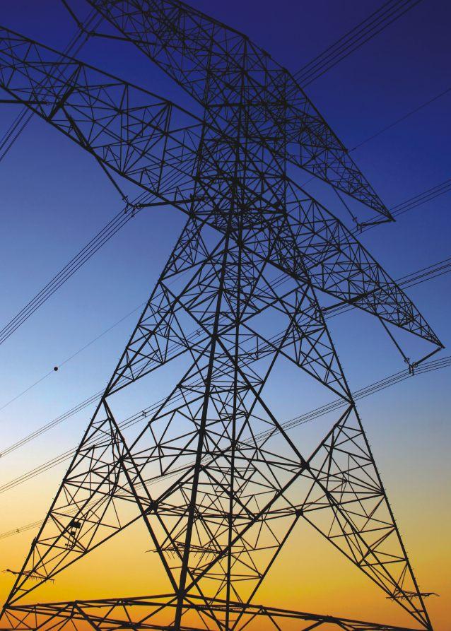
40 Power Cables Powering the world
41 OUTDOOR CABLES L.T. AERIAL BUNCHED CABLE Outdoor Aerial : Aerial Bunched Cables are suitable for the following fuctions: In power theft prone areas. As replacement of bare lines in rural areas, in woods, other localities & narrow street where space is limited. As replacement of bare lines where reliability of supply is of prime importance and where high degree of stability of supply voltage is of importance. In hilly terrains where cost of erection of overhead lines of under ground cable becomes very high. Where space is limited like those in densely populated area, dense forests. As reinforcement of existing system without increasing voltage. For temporary supplies. Typical Cross section for Armoured Cable Ridge for Core Identification XLPE Insulation Aluminium Conductor (Power) Cable Construction Details Conductor Messenger (Neutral Conductor or Otherwise) Insulation Core The phase conductor and neutral/street lighting conductors is of H2 or H4 grade aluminium complying with the requirements of IS 8130:1984 and conforms to flexibility class 2 of IS 8130:1984. The size of the street lighting 2 conductor is16 mm. The conductor is heat treated aluminiummagnesium-silicon alloy wire conforming to IS 398 (Part 4):1979.It is either stranded circular or compacted circular type and has minimum 7 strands with smooth surface. The conductor is insulated with crosslinked polyethylene applied by extrusion. The insulation so applied fits closely on the conductor and it is possible to remove without damaging the conductor. The color of insulation is black, offering UV protection. The phase conductors is provided with Identification one, two or three 'ridges' and outer neutral insulated conductor, if provided, has four 'ridges' for quick identification. The street lighting conductor and messenger conductor (if insulated) does not have any identification mark. Bare Al-Alloy Conductor Aluminium Conductor (Lighting) Assembly (Laying up) The required number of insulated phase conductors, one insulated neutral conductor (if required) and a street lighting conductor (if required) is twisted around the bare (or insulated) as required messenger conductor without fillers with a lay not exceeding 35times the diameter of the insulated phase conductor. The direction of lay is right hand. 42
42 OUTDOOR CABLES Outdoor Aerial Technical Particulars (as Per Is: ) Phase Street Lighting Messenger Conductor Conductor Conductor Aluminium Alloy (Aluminium) (Aluminium) As per IS 398 As per IS 8130 : 1984 As per IS 8130 : 1984 (Part-4) : 1979 Nom. Area Max. D.C. Conductor Nom. Thickness Nom. Area Max. D.C. Conductor Nom. Thickness Nom. Area Max. D.C. Conductor Min. Breaking Resistance of Insulation Resistance of Insulation Resistance Load at 20 C XLPE/PE at 20 C XLPE/P at 20 C Sqmm /Km mm Sqmm /Km mm Sqmm /Km KN Composition & Designation Of L.t. Aerial Bunched Cables Designation Complete Bunched Cable Approx. Overall Dia mm Approx. Total Mass Kg/Km C x 16 mm + 25 mm + 16 mm C x 25 mm + 25 mm + 16 mm C x 35 mm + 25 mm + 16 mm C x 50 mm + 35 mm + 16 mm C x 70 mm + 50 mm + 16 mm C x 95 mm + 70 mm + 16 mm C x 120 mm + 70 mm + 16 mm Notes We can manufacture Aerial Bunched cable as per customer s requirement meeting the National/ International specifications. Advantages Aerial Bunched Cables Lines have very high reliability in maintaining services because conductors are insulated with the best dielectric. The benefits of using this line are: Safest system because phase conductors are insulated, no risk of danger of accidental touching live conductor. Less fault rage on account of good protection against line and ground fault by high winds or falling trees or bird especially in hilly areas & forests as encountered in rural distribution networks. High insulation resistance to earth in all seasons and polluted atmospheres. Negligible leakage currents and low losses. Multiple circuits of power and telephone cables could be strung in the same set of poles or any other supports like walls etc. Better adaptability to run concurrently with existing over-head bare conductor system without any interference. High capacitance and low inductance leading to low impedance of lines. Total lines costs are reduced and maintenance is very easy. Insulation of conductors also helps in preventing corrosion of the conductor. Cores being insulated, the chances of power thefts are eliminated. These are cheaper than underground power cables. Life of Transformers increased as the supply interruptions are minimized. 43
43 OUTDOOR CABLES INSTRUMENTATION CABLE Generally to BS:5308 Part-1 (Polyethylene Insulation) Power Cable Typical Cross section for Armoured Cable Outer Sheath Armour Inner Sheath Overall Scrn. Individual pair Scrn. Core Insulation Copper Conductor Drain Wire Resistance, as per BS 6360 Cross Maximum Resistance at 20 C/Km Sectional Class - 1 Class - 2 Class - 5 Area Solid Copper Conductor Stranded Copper Conductor Flexible Copper Conductor Sqmm Plain Tinned Plain Tinned Plain Tinned Max. Mutual Capacitance Cross Requirment as per BS:5308 Part - 1 Sectional Cable without screen Cables with only collective 1 Pair & 2 Pair with collective Area screen (except 1 & 2 pair) screen & all cables with individual pair screen Sqmm (nf/km) (nf/km) (nf/km) Cable Construction Details Operating Voltage : 300/500V Size : Available in following no of pairs : 1, 2 (1 Quad), 5, 10, 15, 20, 30 and 50 Pairs Conductor: Insulation: Solid/Stranded/Flexible Annealed Bare/Tinned copper class 1/2/5 to BS:6360 Conductors are insulated with solid & Pairing/ Polyethylene Type 03 as per BS:6234, Quading uniformly twisted together to form a pair / quad with a max. lay length of 100 mm, and colour coded for identification. Colour Code: As per BS:5308 Part-1 Pair shield: Each twisted pair shielded with (for individual aluminium backed polyester tape and a pair Shielded tinned copper drain wire of size 0.5mm². cables only) Assembly Overall shield: Bedding: (applicable for Type 2 Cables) Twister pairs are cabled with nonhygroscopic fillers if necessary The entire assembly is shielded with aluminium polyester tape and a tinned copper drain wire of size 0.5mm². Extruded Black Polyethylene Type 2 C or 03 as per BS:6234. Wire Armouring: A serving of round galvanized steel wires (applicable for as per BS:1442 is applied. Type 2 Cables) Sheath: Type - 1 & 2 Extruded Black PVC Type TM1 of BS:6746. L/R ratio (Max): 1.5 Sqmm - 40 Micro Henry/ 0.5/0.75/1.0 Sqmm - 25 Micro Henry/ Note : 1. Type 1 Unarmoured, 2. Type 2 Armoured 3. Other conductor Sizes and Types, Alternative Colour Codes, Higher Pair Count and Sheath Material FR/FRLS/Zero Halogen compounds are available on request. 4. As an alternate, armoured cables shall be supplied with Flat Strip/ Double Steel Tape/ Wire Braided as per customer requirement. 44

44 OUTDOOR CABLES INSTRUMENTATION CABLE Generally to BS:5308 Part-2 (PVC Insulation) Power Cable Typical Cross section for Armoured Cable Outer Sheath Armour Inner Sheath Overall Scrn. Individual Scrn. Core Insulation Copper Conductor Drain Wire Resistance, as per BS 6360 Cross Maximum Resistance at 20 C/Km Sectional Class - 1 Class - 2 Class - 5 Area Solid Copper Conductor Stranded Copper Conductor Flexible Copper Conductor Sqmm Plain Tinned Plain Tinned Plain Tinned Max. Mutual Capacitance at 1 khz. Core to Core : 250 nf/km Core to Screen : 450 nf/km L/R ratio (Max): 1.5 Sqmm - 40 Micro Henry/ 0.5/0.75/1.0 Sqmm - 25 Micro Henry/ Cable Construction Details Operating Voltage : 300/500V Size : Available in following no of pairs : 1, 2 (1 Quad), 5, 10, 15, 20, 30 and 50 Pairs Conductor: Insulation: Solid/Stranded/Flexible Annealed Bare/Tinned copper class 1/2/5 to BS:6360 Conductors are insulated with solid & Pairing/ Polyethylene Type 03 as per BS:6234, Quading uniformly twisted together to form a pair / quad with a max. lay length of 100 mm, and colour coded for identification. Colour Code: As per BS:5308 Part-1 Pair shield: Each twisted pair shielded with (for individual aluminium backed polyester tape and a pair Shielded tinned copper drain wire of size 0.5mm². cables only) Assembly Overall shield: Bedding: (applicable for Type 2 Cables) Twister pairs are cabled with nonhygroscopic fillers if necessary The entire assembly is shielded with aluminium polyester tape and a tinned copper drain wire of size 0.5mm². Extruded Black Polyethylene Type 2 C or 03 as per BS:6234. Wire Armouring: A serving of round galvanized steel wires (applicable for as per BS:1442 is applied. Type 2 Cables) Sheath: Type - 1 & 2 Extruded Black PVC Type TM1 of BS:6746. Note : 1. Type 1 Unarmoured, 2. Type 2 Armoured 3. Other conductor Sizes and Types, Alternative Colour Codes, Higher Pair Count and Sheath Material FR/FRLS/Zero Halogen compounds are available on request. 4. As an alternate, armoured cables shall be supplied with Flat Strip/ Double Steel Tape/ Wire Braided as per customer requirement. 45
45 OUTDOOR CABLES CONTROL CABLE As per IS:1554 (Part-1):1988 Power Cable Typical Cross section for Armoured Cable Outer Sheath Armour Conductor Insulation Inner Sheath 1.1 KV 1.5/2.5 Sqmm (Solid) Multicore Unarmoured PVC Control Cables Conforming to IS : 1554 (Pt - I) No. of Thickness Thickness Thickness Approx. Approx. Standard Current Rating Cores of PVC of PVC of PVC O.D. Net Delivery Direct in In Air/ & Cross Insulation Inner Sheath Outer Weight Length in Ground Duct Sectional (Nom.) (min.) Sheath of Cable Area Extruded (Nom.) No x mm2 mm mm mm mm Kg/Km Mtrs Amps. Amps. 2 x / x / x / x / x / x / x / x / x / x / x / x / x / x / x / x / x / x / x / x / x / x / x / x / x / x / x / x / x / x / x / x / Cable Construction Details Voltage : Size : Conductor: Insulation: These cables can be used on AC voltage up to & Including 1100 V or DC up to & including 1500 V. 1.5 Sq.mm. & 2.5 Sq.mm. upto 37 Cores Annealed Bare Electrolytic Copper/ Aluminum Conductor conforming to IS:8130:1984. Conductors are insulated with PVC Compound as per IS:5831:1984. Colour of Cores: Cores are identified with a colour scheme as per IS:1554 (pt-1):1988 as under 2 Cores - Red & Black 3 Cores - Red, Yellow & Blue 3½ & 4 Cores - Red, Yellow, Blue & Black (Reduced Neutral Core in case of 3½ Core). 5 Cores - Red, Yellow, Blue, Black and Grey In case of cable exceeding five cores, two adjacent (counting and direction cores) in each layer shall be colored Blue, Yellow and remaining cores grey, or identification by numbers printed over insulation as per IS:1554 (pt- 1):1988 Laying of Cores: Cores are laid up with a suitable lay. The final layer direction shall be kept right hand lay. Inner Sheath: Armouring: Outer Sheath: The Inner Sheath is applied over laid up of cores by extrusion/wrapping of thermoplastic material. It is applied over inner sheath. It may consist of galvanized Round Steel wires or galvanized Flat Steel Strips conforming to IS Round Wire armouring is provided, where the calculated diameter under armour is 13.0 mm. Above this, armouring is either round wire/steel strip. A final covering of PVC Compound, conforming to IS:5831:1984, is applied over Armouring in case of Armoured Cable or over Inner Sheath in case of Unarmoured cable, called as Outer Sheath. The Insulation, Inner Sheath or Outer Sheath can be HR PVC, FRLS PVC or FRHF Compound, depending upon their application. Construction Variants 1. Solid / Stranded annealed copper conductor &Tinned / Bare 2. General Purpose / HR PVC insulation 3. Cores laid up ( filled if needed ) 4. FRLS / General Purpose PVC inner sheath 5. FRLS / General purpose PVC Outersheath Max. Conductor D.C. Resistance at 20 Deg C - Conductor Size : 1.5 sq.mm ? / km (Bare), 12.2? / km (Tinned) 2.5 sq.mm ? / km (Bare), 7.56? / km (Tinned) 46

46 OUTDOOR CABLES Power Cable 1.1 KV 1.5/2.5 Sqmm (Solid) Multicore Armoured PVC Control Cables Conforming to IS : 1554 (Pt - I) No. of Thickness Thickness Round Wire Flat Strip Thickness Approx. Approx. Standard Current Rating Cores of PVC of PVC Dia of PVC O.D. Net Weight Delivery Direct In Air/ & Cross Insulation Inner Sheath Outer Sheath of Cable Length in in Ground Duct Sectional (Nom.) (min.) (Min.) Area Extruded No x mm2 mm mm mm Mm Mm Mtrs Kg/Km Mtrs Amps. Amps. 2 x / x / x / x / x / x / x / x x / x x / x x / x x / x x / x x / x x / x x / x / x / x / x / x / x / x / x x / x x / x x / x x / x x / x x / x x / x x / x x / x x / Construction Variants 1. Solid / Stranded annealed copper conductor &Tinned / Bare 2. General Purpose / HR PVC insulation 3. Cores laid up ( filled if needed ) 4. FRLS / General Purpose PVC inner sheath 5. Armouring round Galvanised Steel wires / strips 6. FRLS / General purpose PVC Outersheath Max. Conductor D.C. Resistance at 20 Deg C - Conductor Size : 1.5 sq.mm ? / km (Bare), 12.2? / km (Tinned) 2.5 sq.mm ? / km (Bare), 7.56? / km (Tinned) 47
47 INDOOR CABLES PVC INSULATED INDUSTRIAL CABLE ( UNSHEATHED) These are Single cables/cords with rigid as well as flexible annealed bare/tinned copper and aluminium conductors, insulated with PVC. Indoor Flame Resistant These wires are rated for voltages upto and including 450/750 V AC, 50Hz and used for electric power and lighting including cables for outdoor and low temperature use. These cables may be used on DC system for rated voltages upto and including 1500 V to earth. Typical Cross section PVC Insulation [Single Colour or Dual Colour (Strip on base colour)] Bunched Copper Conductor Nominal Diameter Maximum Electrical Insulation Cable Outer Cross of Single Resistance Wall Diameter Section 20 C (Ù/Km) Thickness Sq mm Max mm Plain Wires Tinned Wires Nominal. mm Nominal Maximum Features: Categories of Cables: Indoor, Outdoor, FR and FR-LSH. Temperature Range: -10 C to +70 C or +85 C. Available in different colors and stripes. Available in Leaded or Lead free grades. Packed in Coils of suitable standard lengths. BIS Certification vide IS 694 Licence No. CM/L Note: Cables upto 300 Sqmm with Flexible conductor (Class 5 of Copper Conductor as per IS 8130 ) can be supplied. Cables upto 630 Sqmm with Rigid conductor (Class 1 or 2 of Copper or Aluminium Conductor as per IS 8130) can be supplied. 48
48 INDOOR CABLES PVC INSULATED INDUSTRIAL CABLE ( SHEATHED) These are Single and multicore cables/cords with rigid as well as flexible annealed bare/tinned copper and aluminium conductors, insulated and sheathed with PVC. Indoor Flame Resistant These wires are rated for voltages upto and including 450/750 V AC, 50Hz and used for electric power and lighting including cables for outdoor and low temperature use. These cables may be used on DC system for rated voltages upto and including 1500 V to earth. Typical Cross section Copper Conductor PVC Insulation Type A IS 5831 PVC Sheath ST-1 IS 5831 Black Nominal Diameter Maximum Electrical Insulation Sheath Cable Outer Cross of Single Resistance Wall Thickness Diameter Section 20 C (Ù/Km) Thickness Sq mm Max mm Plain Wires Tinned Wires Nominal mm. Nominal mm. Nominal Maximum Note: a) Multicore Cables upto 120 Sqmm with Rigid conductor (Class 1 or 2 of Copper or Aluminium Conductor as per IS 8130) can be supplied b) Multicore Cables upto 300 Sqmm with Flexible conductor (Class 5 Copper Conductor as per IS 8130) can be supplied. Typical Cross section Copper Conductor PVC Insulation Type A IS 5831 PVC Sheath ST-1 IS 5831 Black Nominal Diameter Maximum Electrical Insulation Sheath Cable Cross of Single Resistance Wall Thickness Outer Section 20 C (Ù/Km) Thickness Diameter Sq mm Max mm Plain Wires Tinned Wires Min. mm Nominal mm x x5.2 Features: Categories of Cables: Indoor, Outdoor, FR and FR-LSH. Temperature Range: -10 C to +70 C or +85 C x x x6.2 Available in different colors and stripes. Available in Leaded or Lead free grades. Packed in Coils of suitable standard lengths. BIS Certification vide IS 694 Licence No. CM/L
49

50 Speciality Cables Communication... made simple in a special way
51 OUTDOOR CABLES STAINLESS STEEL WIRE ARMOURED TACTICAL CABLE FOR MILITARY APPLICATION Tactical Optical Fibre Cables Indoor / Outdoor Suitable for rapid deployment in extreme environmental conditions. For military application Temporary robust communication lines and mobile applications with Rodent protection Water blocked Flame resistant Aerial Outdoor Shotgun resistant Track resistant (25 kv) Typical Cross section of 4 Fibre Coloured Fibre Jelly Steel Tube Stainless Steel Wire PU / Polyamide Outer Sheath Black PU Sheath Coloured Fibre Jelly Stainless Steel Wire Steel Tube Technical Characteristics FIBRE Color Coding - Fibre & Tube DIAMETER WEIGHT BENDING COUNT SHEATH (mm) (Kg./Km) RADIUS (mm) Max. Nominal Temporary Permanent UPTO 6F Double Sheath D 20D TEMPERATURE RANGE (IEC F1) Installation Operating -10 to +50 C -40 to +70 C 12F Double Sheath D 20D -10 to +50 C -40 to +70 C UPTO 6F Single Sheath D 20D -10 to +50 C -40 to +70 C Blue Orange Green Brown Grey White Red Black Yellow Voilet Pink Aqua Special Features Cut resistant, Polyurethane outer jacket Flexible construction for multiple deployment Performance in wide temp range High permissible tensile strength Excellent protection against rodents and termites Durable in high traffic areas Ruggedized cable and easy to use in the field High impact and crush resistance Drum Length 500/ 1000/ 2000 meters ± 5% Mechanical Characteristics Tensile Strength Permanent Crush Strength Impact Resistance Flex Resistance Storage Temperature Breaking Load Water Pressure 900 N max N/cm 200 (Min.) 2000 Cycle (Min.) C to +65 C >3500 N >500 Bar 52
52 OUTDOOR CABLES FIBRE TO ANTENNA, FTTA SOLUTIONS FOR RADIO BASED STATIONS Outdoor Metro For connection of radio based stations Typical Cross section of 2 Fibre Cable Construction Details Enhance low water peak single mode fibers in full compliance with ITU-T-G.652.D (also available with G657 SM Fibre and OM1 / OM2 / OM3 & OM4 MM Fibre) Polyester Tape Corrugated steel tape LSZH Sheath Nat Nylon-12 Primary Coated Fibre Aramid yarn HDPE Black sheath Tight coated fiber with Ny-12/LSZH Aramid Yarn over tight coated fiber LSZH Sheath over Aramid yarn Polyester tape wrapping Corrugated Steel tape armouring Outer Sheath of UV resistant PE, Black Technical Characteristics FIBRE DIAMETER WEIGHT TENSILE BENDING COUNT (mm) (Kg./Km) STRENGTH (N) RADIUS (mm) Nominal Nominal Installation Operating Temporary Permanent 2F D 20D Installation TEMPERATURE RANGE (IEC F1) Operating -20 to +50 C -40 to +70 C Special Features Fiber-fed remote radios (RRs) offer significant power savings Reduces wind and weight load on towers; avoid costly tower upgrades. Reduces installation cost through fewer cables sheaths (70% less) compared to coax. Reduces installation time through fewer cable sheaths. Fast and easy connection and upgrade via tower-top terminal. Pre-provision for future equipment additions (spare ports). Ruggedized cable with corrugated steel tape armoured providing termite resistance, protection against rodents, birds, squirrels & monkey bite. Mechanical Characteristics Repeated Bending (IEC E6) 30 Cycle, 20 X D, 5 Kg Load, D = Cable D Torsion Resistance (IEC E7) 10 Cycle (± 180 ) 5 Kg Weight, L= 2 Mtr Crush Resistance (IEC E3) 2000 N (100 X 100 mm) for 600 sec Impact Resistance (IEC E4) Kink Resistance (IEC E10) Height 500 mm, Weight = 5 Kg, 3 Nos at different points 20 x D, D = Cable D Drum Length 1000/2000 meters ± 5% 53
53 SPECIALITY CABLES 4 PAIR UTP CAT 5e CABLE 4 Pair Unshielded Twisted Pair (UTP) Data Cable, 24 AWG (0.5mm) Solid Bare Copper Conductors, Polyethylene Insulation, PVC Jacket, Rip Cord. Indoor Flame Resistant These are structured cables suitable for Ethernet and compatible with all known connection systems. Typical Cross section Characteristics Impedance : Conductor Resistance Max O /100m Conductor Resistance Unbalance Max. 5 % PVC Sheath HDPE Insulation Solid Annealed Bare Copper Conductor Rip Cord Mutual Capacitance Max. 5.6 nf/100m Capacitance Earth Unbalance Max. 330 pf/100m Propagation 1 MHZ, Max. 570, 545, MHz & 100 MHz ns/100 m Propagation Delay Skew MHz Max. 45 ns/100 m Features: Fully Complies to the requirements of TIA/EIA 568 C.2. Enhanced performance specification up to 100 MHZ. Cables verified for performance with UL Certification and shipped with UL authorized markings and Labels Colour Code: Pair 1 : White/Blue -Blue; Pair 2 : White/Orange -Orange; Pair 3 : White/Green -Green; Pair 4 : White/Brown -Brown Cable Diameter, Standard Length & Packing: Cable Diameter Available Packaging Available Colour : 5.5 ± 0.5 mm : 305 mtr Pull box Or 500 / 1000 mtr spool : Grey or As Per Customer Requirement Freq Return Insertion NEXT PSNEXT ACRF PSACRF (MHZ) Loss (db) Loss (db) (db) ELFEXT [PSELFEXT] (db/100m) (db) (db) Note: Min. Max. Min. Min. Min. Min Bi-directional Testing for Return Loss, NEXT & PSNEXT 54
54 SPECIALITY CABLES 4 PAIR FTP CAT 5e CABLE 4 Pair Foil Screened Twisted Pair (FTP) Data Cable, 24 AWG (0.5mm) Solid Bare Copper Conductors, Polyethylene Insulation, Overall 100% Screened, PVC Sheath Indoor Flame Resistant Local area network Wide area network Broadband Connectivity Typical Cross section Electrical Characteristics: Conductor Resistance Max O /100m Conductor Resistance Unbalance Max. 5 % PVC Sheath Insulation PE Solid Solid Annealed Bare Copper Conductor Plastic Foil Wrapping Screen (AI/PET) with drain wire Mutual Capacitance Capacitance Earth Unbalance Propagation 1 MHZ, 10 MHz & 100 MHz Propagation Delay Skew MHz Max. 5.6 nf/100m Max. 330 pf/100m Max. 570, 545, 538 ns/100 m Max. 45 ns/100 m Colour Code: Pair 1 : White/Blue -Blue; Pair 2 : White/Orange -Orange; Pair 3 : White/Green -Green; Pair 4 : White/Brown -Brown Standard Length & Packing: Cable Diameter : 6.0 ± 0.5 mm Available Packaging : 305 mtr Pull box Or 500 / 1000 mtr spool Freq Return Insertion NEXT PSNEXT ACRF PSACRF (MHZ) Loss (db) Loss (db) (db) ELFEXT [PSELFEXT] (db/100m) (db) (db) Min. Max. Min. Min. Min. Min Note: Bi-directional Testing for Return Loss, NEXT & PSNEXT 55
55 SPECIALITY CABLES 4 PAIR SFTP CAT 5E CABLE 4 Pair Foil & Braid Screened Twisted Pair (SFTP) Data Cable, 24 AWG (0.5mm) Solid Bare Copper Conductors, Polyethylene Insulation, Overall 100% Screened, Braided with Tinned Copper PVC Sheath These are structured cables suitable for Ethernet and compatible with all known connection systems. Indoor Flame Resistant Typical Cross section Electrical Characteristics: FR PVC Jacket Tinned Copper Braid HF Screen (AI-PET) (with 24AWG ATC drain wire) Plastic Foil Wrapping Insulation PE Solid Solid Annealed Bare Copper Conductor Conductor Resistance Max O /100m Conductor Resistance Unbalance Max. 5 % Mutual Capacitance Max. 5.6 nf/100m Capacitance Earth Unbalance Max. 330 pf/100m Propagation 1 MHZ, Max. 570, 545, 538 ns/100 m 10 MHz & 100 MHz Propagation Delay Skew MHz Max. 45 ns/100 m Colour Code: Pair 1 : White/Blue -Blue; Pair 2 : White/Orange -Orange; Pair 3 : White/Green -Green; Pair 4 : White/Brown -Brown Cable Diameter, Standard Length & Packing: Cable Diameter : 7.0 ± 0.5 mm Standard Length : 500mtr ± 10% spools Available Packaging : Spools packed in carton box Freq Return Insertion NEXT PSNEXT ACRF PSACRF (MHZ) Loss (db) Loss (db) (db) ELFEXT [PSELFEXT] (db/100m) (db) (db) Min. Max. Min. Min. Min. Min Note: Bi-directional Testing for Return Loss, NEXT & PSNEXT 56
56 SPECIALITY CABLES HYBRID CABLE 4 PAIR UTP CAT 5e WITH 2 NO. OF G-652D FIBRE 4 Pair Unshielded Twisted Pair (UTP) 100 Ohm Data Cable, 24 AWG (0.5mm) Solid Bare Copper Conductors, Polyethylene Insulation along with 2 Fibre as per G-652 D Rec placed inside loose tube made of PBTP filled with thixotropic jelly, Core wrapped with polyester tape, PVC /FRLSZH Jacket, Rip Cord. Indoor Flame Resistant The cable is particularly suitable for indoor star network and internal wiring in connector. Suitable for Ethernet and compatible with all known connection systems. Typical Cross section Features: PVC Sheath (with Rip Cord) Central Strength Member HDPE Insulation Loose tube with fibre and jelly Solid Annealed Bare Copper Conductor Core Wrapping of Polyester Tape Electrical Characteristics: Conductor Resistance Max O /100m Conductor Resistance Unbalance Max. 5 % Mutual Capacitance Max. 5.6 nf/100m Capacitance Earth Unbalance Max. 330 pf/100m Propagation 1 MHZ, Max. 570, 545, 538 ns/100 m 10 MHz & 100 MHz Propagation Delay Skew MHz Max. 45 ns/100 m Optical Characterisitics: 1310 nm Max db/km 1550 nm Max db/km Dispersion, nm Max 3.5 ps/nm.km Dispersion, 1550 nm Max 18 ps/nm.km PMD Max 0.2 ps/sqrt(km) Other Characterisitics: Tensile Force Installation Max KN Tensile Force Installed Max KN Temperature range Operation -40 C to + 60 C Temperature range Storage -40 C to + 70 C Temperature range Installation -15 C to + 40 C?Copper pairs fully Complies to the requirements of TIA/EIA 568 C.2.??? Enhanced performance specification up to 100 MHz. Available in Lead Free form as well. Fibre used fully complies to ITU-T Rec G652D Colour Code: CU. Pair Pair 1 : White/Blue Fibre Fibre 1: White Pair 2 : White/Orange Fibre 2: Red Pair 3 : White/Green Pair 4 : White/Brown Cable Diameter, Standard Length & Packing: Freq Return Insertion NEXT PSNEXT ACRF PSACRF (MHZ) Loss (db) Loss (db) (db) ELFEXT [PSELFEXT] (db/100m) (db) (db) Min. Max. Min. Min. Min. Min Cable Diameter Cable Weight : 6.0 ± 0.5 mm : 40 Kg/Km Nominal Available Packaging : 500 mtr spool ± 10% Available Colour : Grey or As Per Customer Requirement 57
57 SPECIALITY CABLES 4 PAIR UTP CAT 5e ARMOURED LSZH CABLE 4 Pair Unshielded Twisted Pair (UTP) 100 Ohm Data Cable, 24 AWG (0.5mm) Solid Bare Copper Conductors, Polyethylene Insulation, LSZH Sheath, Steel Wire Armour, LSZH Jacket Flame Resistant Indoor These are structured cables suitable for Ethernet and compatible with all known connection systems. Typical Cross section Electrical Characteristics: Conductor Resistance Max O /100m Conductor 24AWG ABC Insulation HDPE Core Wrap (Optional)-PET Inner Sheath: LSZH Grey (0.5 mm Nominal Thickness) Armour: Galvanized Steel Wire Outer Sheath: LSZH Black (1.0 mm Nominal Thickness) Conductor Resistance Unbalance Max. 5 % Mutual Capacitance Max. 5.6 nf/100m Capacitance Earth Unbalance Max. 330 pf/100m Propagation 1 MHZ, Max. 570, 545, 538 ns/100 m 10 MHz & 100 MHz Propagation Delay Skew MHz Max. 45 ns/100 m Features: Fully Complies to the transmission requirements of TIA/EIA 568 C.2. Enhanced performance specification up to 100 MHZ. Excellent Mechanical protection with Galvanised Steel Wire Armouring Colour Code: Pair 1 : White/Blue -Blue; Pair 2 : White/Orange -Orange; Pair 3 : White/Green -Green; Pair 4 : White/Brown -Brown Cable Diameter, Standard Length & Packing: Cable Diameter : 9.0 ± 0.5 mm Available Packaging : 500 mtr ± 10% Freq Return Insertion NEXT PSNEXT ACRF PSACRF (MHZ) Loss (db) Loss (db) (db) ELFEXT [PSELFEXT] (db/100m) (db) (db) Note: Min. Max. Min. Min. Min. Min Bi-directional Testing for Return Loss, NEXT & PSNEXT 58
58 SPECIALITY CABLES 4 PAIR UTP CAT 6 CABLE 4 Pair Unshielded Twisted Pair (UTP) Data Cable, 23 AWG (0.56mm) Solid Bare Copper Conductors, Polyethylene Insulation, Separator, PVC Jacket, Rip cord Indoor Flame Resistant These are structured cables for campus, riser and horizontal installations. Suitable for Ethernet and compatible with all known connection systems. Ideal for high performance workstation applications including voice/ data systems, digital video, broadband and voice over internet protocol, etc. Typical Cross section Electrical Characteristics: Conductor Resistance Max O /100m PVC Sheath HDPE Insulation Solid Annealed Bare Copper Conductor Separator Rip Cord Conductor Resistance Unbalance Max. 5 % Mutual Capacitance Max. 5.6 nf/100m Capacitance Earth Unbalance Max. 330 pf/100m Propagation 1,10,100,250MHz Max. 570, 545, 538 & 536 ns/100 m Propagation Delay Skew MHz Max. 45 ns/100 m Features: Fully Complies to the requirements of TIA/EIA 568 C.2. Enhanced performance specification up to 250 MHz. Cables verified for performance with UL Certification and shipped with UL authorized markings an Labels Colour Code: Pair 1 : White/Blue -Blue; Pair 2 : White/Orange -Orange; Pair 3 : White/Green -Green; Pair 4 : White/Brown -Brown Cable Diameter, Standard Length & Packing: Cable Diameter : 6.35 mm (Max.) Available Packaging : 305 mtr Pull box Or 500 Available Colour / 1000 mtr spool : Grey or As Per Customer Requirement Freq Attenuation NEXT PSNEXT ACRF PSACRF Return TCL ETCL (MHZ) (db/100m) (db) (db) (ELFEXT) [PSELFEXT] Loss (db) (db) (db) (db) (db) Note: Max. Min. Min. Min. Min. Min. Min Min @ MHz Bi-directional Testing for Return Loss, NEXT & PSNEXT 59
59 SPECIALITY CABLES 2 / 4 PAIR CAT 5 DROP CABLE (SINGLE SHEATH) 2 / 4 Pair Unshielded twisted pair (UTP) drop Cable, 24 AWG (0.5mm) Solid bare copper conductors, Polyethylene Insulation, PE Jacket, Rip Cord. Outdoor Underground These are drop cables used for broadband connectivity in residential buildings/houses, inter building cabling etc. Typical Cross section Electrical Characteristics: Conductor Resistance 86 ± 6 O /Km PE Sheath Aramid Yarn Polyester Tape HDPE Insulation Copper Conductor Conductor Resistance Unbalance Max. 5 % (Individual), Max. 2% (Average) Mutual Capacitance Max. 56 nf/km Capacitance Earth Unbalance Max. 330 pf/100m Characteristics Impedance at MHz 100 ± 15 Propagation Delay Skew MHz Max. 45 ns/100m Features: Good Mechanical Protection Suitable for use outside buildings with UV resistant sheath Enhanced performance specification upto 100 MHz Colour Code: Pair 1 : White -Blue; Pair 2 : White -Orange; Pair 3 : White -Green; Pair 4 : White -Brown Cable Diameter, Standard Length & Packing: Cable Diameter : 4 Pair 5.7 ± 0.5 mm Freq Attenuation NEXT Return (MHz) (db/100m) (db) Loss (db) Max. Min. Min. Note: Bi-directional Testing for Return Loss, NEXT & PSNEXT 2 Pair 4.5 ± 0.5 mm Available Packaging : 305 mtr Pull box Or 500 / 1000 mtr spool 60
60 SPECIALITY CABLES 2 / 4 PAIR CAT 5 DROP CABLE (DOUBLE SHEATH) 2 / 4 Pair Unshielded twisted pair (UTP) drop Cable, 24 AWG (0.5mm) Solid bare copper conductors, Polyethylene Insulation, PVC Sheath, Aramid Yarns, PE Jacket, Rip Cord. Outdoor Underground These are drop cables used for broadband connectivity in residential buildings/houses, inter building cabling etc. Typical Cross section Electrical Characteristics: Conductor Resistance 86 ± 6 O /Km PE Sheath Aramid Yarn PVC Sheath Polyester Tape HDPE Insulation Copper Conductor Conductor Resistance Unbalance Max. 5 % (Individual), Max. 2% (Average) Mutual Capacitance Max. 56 nf/100m Capacitance Earth Unbalance Max. 330 pf/100m Propagation Delay Skew MHz Max. 45 ns/100m Features: Good Mechanical Protection Suitable for use outside buildings with UV resistant sheath Enhanced performance specification upto 100 MHz Colour Code: Pair 1 : White -Blue; Pair 2 : White -Orange; Pair 3 : White -Green; Pair 4 : White -Brown Cable Diameter, Standard Length & Packing: Cable Diameter 4 Pair: 7.0 ± 0.5 mm Freq Attenuation NEXT Return (MHz) (db/100m) (db) Loss (db) Max. Min. Min. Note: Bi-directional Testing for Return Loss, NEXT & PSNEXT 2 Pair: 5.9 ± 0.5 mm Available Packaging : 305 mtr Pull box Or 500 / 1000 mtr spool 61
61 SPECIALITY CABLES 2 Pair / 4 Pair Data Communication Cable These are PE Insulated 0.4mm Annealed Tinned Copper Conductor, Overall Screened, Tinned Copper Braid and Halogen Free Flame Retardant Sheathed Communication Cables. Flame resistant Indoor Metro Halogen Free cable intended for Indoor use for data communication Typical Cross section 2 Pair Typical Cross section 4 Pair Sheath FRPE (Halogen Free) Tinned Copper Braid HF Screen (Al-PE-Al) Drain Wire Solid Tinned Plastic Foil Wrapping Insulation PE Solid Solid Annealed Tinned Copper Conductor Sheath FRPE (Halogen Free) Tinned Copper Braid HF Screen (Al-PE-Al) Plastic Foil Wrapping Insulation PE Solid Solid Annealed Tinned Copper Conductor Features: UL Approved Cable (UL 444 Listed) Excellent level of fire retardancy (Meets UL CMR requirements) Good Flexibility RoHS Compliant Mechanical & Environmental Properties: Bending Radius Standard Length & Packing: 2 Pair 4 Pair Min. 27 mm Pulling Force Max. 25 N Max. 50 N Operating Temperature - 20 C to + 75 C - 20 C to + 75 C Fire Properties UL 1685 Ft4, UL 444 CMR IEC C Cable Diameter 4.5 mm ± 0.5mm 5.5 mm ± 0.5mm Colour Code: Pair 1: White-Blue; Pair 2: White-Orange; Pair 3: White-Green; Pair 4- White-Brown Min. 22 mm 600 mtrs ± 10% OR in further multiples of 150 mtrs Electrical Characteristics: Conductor Resistance Max. 153 O /Km Max. 153 O /Km Conductor Resistance Max 2 % Max 4 % Unbalance Mutual Capacitance Nom. 49 nf/km Nom. 53 nf/km Capacitance Earth Max pf/km Max pf/km Unbalance Insulation Resistance Min MO Km Min MO Km Dielectric Strength Conductor to Conductor Conductor to Shield 2.5 KV, 2 Sec 2.5 KV, 2 Sec Characteristics Impedance at 1 Mhz120 ± 15 O 100 ± 10 O Attenuation at 1 MHz Max. 3.3 db/100m Attenuation at 1, 4, 10 Max. 3.2, 6.5, 10,13 16, 31.2, 62.5, 100MHz 17, 23, 30dB/100m Near End Cross Talk at 1 MHZ Min. 52 db Near End Cross Talk Min. 62, 53, 47, 44 at 1, 4, 10, 16, , 35, 32dB 62.5, 100MHz Far End Cross Talk at 1 MHz Propagation Delay 2 Pair 4 Pair Min m Min. 4.7ns/m; Max.5.05 ns/m Wound in Wooden Spools packed in cardboard Cartons 62
62 SPECIALITY CABLES 24 PAIR DATA COMMUNICATION CABLE 24 Pair Screened Cables with 0.4 mm Copper Conductor, HDPE Insulation, Core Wrap, Screened, PVC Sheathed Communication Cables. This is a Screened Cable used for Linking ADSL Netwroks Indoor Flame Resistant Typical Cross section Electrical Characteristics: Conductor Resistance Max. 148 O /Km Sheath FR PVC Screen (Al-PET) (with 0.4mm ATC drain Wire) Plastic Wrapping Tape Insulation PE Solid Solid Annealed Copper Conductor Rip Cord Mutual Capacitance Max. 56 nf/km Capacitance Unbalance (Pair to Pair) Max. 500 pf/km Capacitance Earth Unbalance Max pf/km Dielectric Strength 1.0 KV DC, 1 Minute Characteristics Impedance at 1 MHz to 16 Mhz 100 ± 15 O Attenuation at 1, 2, 3, 8, 10, 16 MHz Max. 2.8, 3.9, 4.5, 7.5, 8.6, 10.5 db/100m Near End Cross Talk at 1, 2, 3, Min. 55, 50, 46, 41, 40, 8, 10, 16 MHz 37 db Features: Low Cross talk and excellent Electromagnetic Compatibility Easy to Install Guaranteed data speeds through enhanced electrical performance upto 16 MHz RoHS Compliant Working temperature from 20 C to +75 C Mechanical & Environmental Properties: Jacket Cold Bend Standard Length & Packing: No crack after 4 Hrs test (-20 C) Operating Temperature - 20 C to + 75 C Cable Diameter 500 mtrs ± 10% Wound & Packed in Wooden Drums 9.5 ± 0.5 mm Colour Code: Pair 1: White Blue Pair 2: White Orange Pair 3: White Green Pair 4: White Brown Pair 5: White Grey Pair 6: Red Blue Pair 7: Red Orange Pair 8: Red Green Pair 9: Red Brown Pair 10: Red Grey Pair 11: Black Blue Pair 12: Black Orange Pair 13: Black Green Pair 14: Black Brown Pair 15: Black Grey Pair 16: Yellow Blue Pair 17: Yellow orange Pair 18: Yellow Green Pair 19: Yellow Brown Pair 20: Yellow Grey Pair 21: White/Blue Blue Pair 22: White/Blue Orange Pair 23: White/Blue Green Pair 24: White/Blue Brown 63
63 INDOOR CABLES SWITCHBOARD CABLES (SCREENED / UNSCREENED) Indoor Flame Resistant These Cables are used for Internal wiring in Telephone Exchanges, bay-to-bay wiring, equipment to MDF wiring etc and in subscriber offices in large buildings. Typical Cross section for Armoured Cable Features: Available in standard conductor sizes of 0.4mm, 0.5mm & 0.6mm Diameter. Sheath (PVC) Optional Screen (Al-PET) (with ATC drain Wire) Plastic Wrapping Tape Insulation PE/PVC Solid Solid Annealed Tinned Copper Conductor Rip Cord Available in 1 Pair to 128Pair & more if required. Meets the flammability test requirement as per IEC 332 (Part-1) TEC approved cable as per GR/WIR-06/03 Mar 2002 Electrical Characteristics: Conductor Resistance 0.4mm Max. 143 /Km 0.5mm Max 92.2 /Km 0.6mm Capacitance Unbalance (Pair to Pair) Max 64.0 /Km Max. 230 pf/km Colour Code: For Insulation of 1 Pair / 2 Pair/ 3 Pair / 4 Pair / 5 Pair / 10 Pair / 20 Pair Unit Pair 1: White-Blue Pair 11: Black-Blue Pair 2: White-Orange Pair 12: Black-Orange Pair 3: White-Green Pair 13: Black-Green Pair 4: White-Brown Pair 14: Black-Brown Pair 5: White-Grey Pair 15: Black-Grey Pair 6: Red-Blue Pair 16: Yellow-Blue Pair 7: Red-Orange Pair 17: Yellow-Orange Pair 8: Red-Green Pair 18: Yellow-Green Pair 9: Red-Brown Pair 19: Yellow-Brown Pair 10: Red-Grey Pair 20: Yellow-Grey Insulation Resistance at 50 C Min. 50 M Km Dielectric Strength 3.0 KV DC, 1 Minute Environmental Properties: Operating Temperature - 20 C to + 75 C Flameability IEC 332 (Part 1) Standard Length & Packing: As per customer requirement. Wound & Packed in Wooden Drums / Coils / Spools as per size and standard length For Insulation Of 8 Pair Pair 1: Pair 2: Pair 3: Pair 4: White-Blue White-Orange White-Green White-Brown Pair 5: Pair 5: Pair 7: Pair 8: Red-Blue Red-Orange Red-Green Red-Brown For 8 Pair Sub-unit Binder Colours of 32 Pair Binder 1: Blue Binder 2: Orange Pair 3: Pair 4: Green Brown For 32 Pair Unit Binder Colours of 128 Pair Binder 1: White Binder 2: Red Pair 3: Pair 4: Black Yellow 64
64 INDOOR CABLES SCREENED PCM CABLES Solid / Foam Skin Insulated, Individual Screened Twisted Pairs, PVC Sheathed, Overall Screened Telecommunication Cables Indoor Metro : Digital equipment wiring to work up to 2 M bits/sec. Typical Cross section for Armoured Cable Features: Conductor Pair Wrap Drain Wire Available in standard conductor sizes of 0.5mm diameter. Available in 1 Pair to 16 Pair and more if required. Meets the flammability test requirement as per IEC 332 (Part-1) Pair Screening Core Screening Outer Wrapping Rip Cord Sheathing TEC approved cable as per GR/WIR-04/02 Nov 2001 Excellent protection to cross-talk and Electromagnetic Induction Electrical Characterisitics: Resistance Conductor Resistance 0 at 20 C ( O /Km ) 86 ± 3 Resistance Unbalance (%) Insulation Resistance at 500 V Dc(M O Km) 10,000 Dielectric Strength 2.5 (Max. Indiv.) 1.0(Max. Avg.) KV Dc for 3 seconds With stands Capacitance Mutual capacitance at 1 KHz (nf/km) 45 ± 5 Earth capacitance unbalance (pf/500m) Impedance 2000 (Max.) Characteristics impedance at 1 MHZ (O ) 120 ± 10 Attenuation Attenuation at 20 c at 1 MHz (db/km) 20 db/km (Max.) Cross Talk [pair to pair within unit] Near end cross talk at 1 MHZ (db) Far end cross talk at 1 MHZ (db/km) Colour Coding 85 (Min.) 67 (Min.) Each pair shall be Red for Wire-1 and Blue for Wire-2, with serial number of the pair viz. 1 to 10/16, marked at regular interval, on the outer surface of the Aluminium film used for Pair Screening. Cable Diameter, Standard Length & Packing: Cable Diameter : 10 P: 15 mm (Maximum) 16 P: 18 mm (Maximum) Standard Length : 500 mtr ± 10% Packing : Wound and packed in wooden drums 65
65 SPECIALITY CABLES 50 Ohm COAXIAL CABLE Outdoor Underground Typical Cross section Electrical Characteristics: Cable Diameter, Standard Length & Packing:
66 SPECIALITY CABLES AUTOMOBILE WIRES These are PVC Insulated Single Core Thin-Wall type Low Voltage and Light Weight Auto Wires conforming to International DIN, JIS & JASO Standards. Range of Cables includes FLRY, AV, AVS and AVSS types. These wires are used in manufacturing of Wiring Harness for Automobile Industry where high flexibility, thermo and mechanical strength are required. Indoor Flame Resistant Typical Cross section PVC Insulation [Single Colour or Dual Colour (Strip on base colour)] Bunched Copper Conductor FLRY-B Type Wires (DIN Part 5 & 6) Nominal No. of Diameter Diameter Electrical Insulation Cable Cable Cross Strands of Single of Cond- Resistance Wall Outer Weight Section Wire 20 C Thickness Diameter Approx. Sq mm Max mm Max mm mù/m Min. mm mm Kg/Km Features: Manufactured within the Quality System certified as per TS 16949:2002 Resistant to heat, oil, abrasion and cold. Excellent flexibility. Temperature Range of DIN Wires: 40 C to +105 C. Temperature Range of JIS & JASO Wires : 40 C to +85 C. Available in different colors and stripes. Available in Leaded or Lead free grades. Packed in Coils of suitable standard lengths (Max) (Max) AVS Type Wires (JASO D 611) Nominal No. of Diameter Diameter Electrical Insulation Cable Cable Cross Strands of Single of Cond- Resistance Wall Outer Weight Section Wire 20 C Thickness Diameter Approx. Sq mm Max mm Max mm mù/m Min. mm mm Kg/Km f AVSS Type Wires ( JASO D 611) Nominal No. of Diameter Diameter Electrical Insulation Cable Cable Cross Strands of Single of Cond- Resistance Wall Outer Weight Section Wire 20 C Thickness Diameter Approx. Sq mm Max mm Max mm mù/m Min. mm mm Kg/Km f f f AV Type Wires (JIS C 3406) Nominal No. of Diameter Diameter Electrical Insulation Cable Cable Cross Strands of Single of Cond- Resistance Wall Outer Weight Section Wire 20 C Thickness Diameter Approx. Sq mm Max mm Max mm mù/m Min. mm mm Kg/Km 0.5f f

67 Complete Solutions For All Needs EPC Division


68 Birla Ericsson Optical Ltd. We offer complete turnkey services for Engineering, design, supply, construction, installation, testing & commissioning for: Telecom Sector Turnkey projects of Optical fibre cabling. Complete Infrastructure for Telecom Towers. Intracity HDD Broadband network. Power Sector EHV Cabling Projects. Rural Electrification projects. Transmission Lines. Transmission and Distribution substations. Lighting Projects. 69


69 Strength beyond Imagination
70 FRP Rods Fiber Reinforced Plastic (FRP Rod) Used as Di electric composite strength member in Optic Fibre Cables It is a di-electric composite cable strength member widely known as FRP/ GRP rod. It is designed to provide excellent tensile strength performance while maintaining high degree of stiffness, preventing cable buckling over its entire service life. It is most suited for loose tube, uni-tube, slotted core or ribbon cable, typically used as central or peripheral reinforcement in fiber optic cables. FRP rods serve a dual purpose. The lightweight FRP prevents the cable from sagging in aerial installations and its rigidity and strength takes on the load of cable. FRP combines the properties of high performance glass fibers and polymer resin to give a cost effective and superior strength member for cables. FRP strength members are also widely used in various copper cables for last mile connectivity as well as power transmission. It provides cable reinforcement during installation, reduces tension on signal carrying optic fiber/ conductor. Features: Light Weight & Excellent Tensile Strength Prevent Cable buckling FRP Rod Most Suited for Multi-Loose tube Tube, Uni Tube, Slotted Core & Ribbon Cable Designs. Used as central or peripheral reinforcement in fibre optic cable Dual Advantage : Reinforcement during installation as well as reduce stress on signal carrying optic fibre /conductor Prevent sagging in aerial installation Cost effective solution as a strength member Description It is manufactured using E-glass fibre with heat resistant thermal resin system. It is available in various coatings including EAA, Tuff, Mega Bond and HDPE, which allows easy handling, Tuff coating provides very smooth surface, whereas Mega bond is suitable for where high adhesion to up jacketing is desired Product Range Available diameter: 0.4 mm up to 5.0 mm ( 0.4, 0.8, 0.9, 1.0, 1.1, 1.2, 1.5, 1.6, 1.8, 2.0, 2.1, 2.2, 2.3, 2.5, 2.7, 2.8, 3.0, 3.5, 4.0, 4.5, 5.0 ). Physical Property Glass content 75 to 85% by weight Density 2.05 to 2.15 gms/ cc Diameter stability ±0.05 mm of ordered diameter Ovality <(=)0.05 mm Splices None Mechanical Property Property Unit Specification Test Method Tensile Strength at Break Kg/mm² > 140 ASTM D 3916 Tensile modulus Kg/mm² > 5000 ASTM D 3916 Elongation at break % > 2.5% & < 4% ASTM D 3916 Flexural modulus Kg/mm² > 5000 ASTM D 790 Flexural Strength Kg/mm² > 70 ASTM D 790 Water Absorption after 24 hrs. % < 0.1 ASTM D 570 Min. Bending Radius at 25 C mm (=) <25 D Typical Packing Description Spool Dimensions in mm Flange Dia Barrel Dia Traverse O.A Width Centre Bore CB to DPC FRP Rod Length in K.M 0.8 mm to 1.2 mm mm to 2.0 mm mm to 2.5 mm mm to 3.5 mm mm to 5.0 mm

71 Fibre Properties Specification of Multi Mode Optical fibre OM1(62.5/125ìm) OM2(50/125ìm) (OM3) (OM4) Transmission Properties Unit Values Values Values Values Attenuation at 850 nm db/km < / = 3.0 < / = 2.9 < / = 2.9 < / = 2.9 Attenuation at 1300 nm db/km < / = 0.7 < / = 0.9 < / = 0.9 < / = 0.9 Bandwidth at 850 nm MHzKm > / = 200 > / = 500 > / = 1500 > / = 3500 Bandwidth at 1300 nm MHzKm > / = 500 > / = 500 > / = 500 > / = 500 Numerical Aperture ± ± ± ± Geometrical Properties Unit Values Values Values Values Core diameter µ m 62.5 ± ± ± ± 3.0 Cladding diameter µ m 125 ± ± ± ± 2 Core noncircularity % < / = 5 < / = 5 < / = 5 < / = 5 Cladding noncircularity % < / = 1 < / = 2 < / = 2 < / = 2 Core concentricity error µ m < / = 1.5 < / = 2.0 < / = 2.0 < / = 2.0 Primary coating diameter µ m 245 ± ± ± ± 10 Mechanical properties Unit Values Values Proof test for minimum strain level and Duration of proof test kpsi, Sec > / = 100 > / = 100 > / = 100 > / = 100 Change in Attenuation with Bending 100 Turns on 75mm Dia. Mandrel at 850 db < / = 0.50 < / = 0.50 < / = 0.50 < / = Turns on 75mm Dia. Mandrel at 1300 db < / = 0.50 < / = 0.50 < / = 0.50 < / = 0.50 Strippability force to remove primary coating of fibre Newton 1.3 to to to to 8.9 Fibre Curl Radius of curve > / = 4 Mtr > / = 4 Mtr > / = 4 Mtr > / = 4 Mtr Dynamic tensile strength (unaged) kpsi > / = 550 > / = 550 > / = 550 > / = 550 Dynamic tensile strength (Aged) kpsi > / = 440 > / = 440 > / = 440 > / = 440 Dynamic Fatigue > / = 18 > / = 18 > / = 18 > / = 18 Environmental Properties Unit Values Values Values Values Induced attenuation at 850 nm & 1300 nm for 0 0 Temp. & Humidity cycle from -10 C to +85 C 0 at 98 % humidity (min), ref temp 23 C db/km < / = 0.15 < / = 0.15 < / = 0.15 < / = 0.15 Induced attenuation at 850 nm & 1300 nm for 0 0 Temperature cycle from -60 C to +85 C, 0 ref temp 23 C db/km < / = 0.15 < / = 0.15 < / = 0.15 < / = 0.15 Induced attenuation at 850 nm & 1300 nm for 0 Water Immersion at 23 ± 2 C db/km < / = 0.15 < / = 0.15 < / = 0.15 < / = 0.15 Induced attenuation at 850 nm & 1300 nm for 0 Accelerated Ageing (Temperature) at 85 ± 2 C, 0 ref temp 23 C db/km < / = 0.15 < / = 0.15 < / = 0.15 < / =
72 Specification of Single Mode Matched Clad Type & Non Zero Dispersion Optical fibre ITU-T Rec. ITU-T Rec. ITU-T Rec. G-652.D G-655 G-657.A/IEC B6 Transmission Properties Unit Values Values Values Attenuation at 1310 nm db/km < / = < / = 0.35 Attenuation at 1550 nm db/km < / = 0.22 < / = 0.24 < / = 0.22 Attenuation at 1625 nm db/km < / = 0.25 < / = 0.26 < / = 0.25 Attenuation at 1383± 3 nm db/km < / = < / = 0.32 Point discontinuity db < / = 0.05 < / = 0.05 < / = 0.05 Difference in maximum attenuation in the range from 1285 to 1330 nm w.r.t attenuation at 1310 nm db/km < / = < / = 0.03 Difference in maximum attenuation in the range from 1530 to 1570 nm w.r.t attenuation at 1550 nm db/km < / = 0.02 < / = 0.03 < / = 0.02 Max. chromatic dispersion at nm wavelength range ps/nm.km < / = < / = 3.5 Max. chromatic dispersion at nm wavelength range ps/nm.km < / = < / = 5.3 Max. chromatic dispersion at nm wavelength range ps/nm.km to Max. chromatic dispersion at nm wavelength range ps/nm.km to Chromatic dispersion at 1550 nm ps/nm.km < / = < / = 18.0 Zero dispersion wavelength nm 1302 to to 1322 Zero dispersion slope nm^2.km < / = < / = PMD at 1310 & 1550 nm (individual) ps/sqrt.km < / = 0.20 < / = 0.20 < / = 0.20 Link PMD ps/sqrt.km < / = 0.06 < / = 0.04 < / = 0.06 Fibre cut-off wavelength nm < / = < / = 1320 Mode field diameter range at 1310 nm µ m 9.2 ± ± 0.4 Mode field diameter range at 1550 nm µ m 10.5 ± ± ± 0.5 Geometrical Properties Unit Values Values Values Cladding diameter µ m 125 ± ± ± 0.7 Cladding noncircularity % < / = 0.7 < / = 0.7 < / = 0.7 Primary coating diameter (uncoloured) µ m 245 ± ± ± 5 Core/Clad concentricity error µ m < / = 0.5 < / = 0.5 < / = 0.5 Coating / Cladding Concentricity error µ m < / = 10 < / = 12 < / = 10 Mechanical properties Unit Values Values Values Proof test for minimum strain level and Duration of proof test kpsi, Sec > 100 > 100 > 100 Change in Attenuation with Bending 100 Turns on 60mm Dia. Mandrel at 1310 db < / = Turns on 60mm Dia. Mandrel at at 1550 db < / = 0.05 < / = 0.05 < / = Turns on 60mm Dia. Mandrel at at 1625 db - < / = 0.01 < / = Turn on 32 mm Dia. Mandrel at 1310 db < / = Turn on 32 mm Dia. Mandrel at 1550 db < / = 0.5 < / = Turn on 32 mm Dia. Mandrel at 1625 db - < / = Turn on 10 mm Dia. Mandrel at 1550 db - - < / = Turn on 10 mm Dia. Mandrel at 1625 db - - < / = 0.5 Strippability force to remove primary coating of fibre Newton 1.3 < F < < F < < F < 8.9 Fibre Curl Radius of curve > / = 4 Mtr > / = 4 Mtr > / = 4 Mtr Dynamic tensile strength (unaged) kpsi > / = 550 > / = 550 > / = 550 Dynamic tensile strength (Aged) kpsi > / = 440 > / = 440 > / = 440 Dynamic Fatigue - > / = 20 > / = 20 > / = 20 Environmental Properties Unit Values Values Values Induced attenuation at 1310 nm & 1550 nm for Temp. & Humidity cycle from -10 C to +85 C at 98 % humidity (min), ref temp 23 C db/km < / = 0.05 < / = 0.05 < / = 0.05 Induced attenuation at 1310 nm & 1550 nm for Temperature cycle from -60 C to +85 C, ref temp 23 C db/km < / = 0.05 < / = 0.05 < / = 0.05 Induced attenuation at 1310 nm & 1550 nm for 0 Water Immersion at 23 ± 2 C db/km < / = 0.05 < / = 0.05 < / = 0.05 Induced attenuation at 1310 nm & 1550 nm for 0 0 Accelerated Ageing (Temperature) at 85 ± 2 C, ref temp 23 db/km < / = 0.05 < / = 0.05 < / = 0.05 Note : Other values of G655 Fibre such as Dispersion and MFD can also be provided on request. 73
73 OPTICAL FIBRE CABLE HANDLING, INSTALLATION & SAFETY INSTRUCTION Optical fibre cables can be easily damaged if they are improperly handled or installed. It is imperative that certain procedure be followed during Handling & Installation of these cables to avoid damage. Optical fibre cable requires special care during Handling & Installation to ensure reliable operation. This information given in the document is for Handling drum at various places from receiving in stores till shipment to the site for installation. Proper handling of cable drum decreases probability of accidental damage of cable and personnel. This document also contain some of the basic safety information applicable to Optical fiber cable. Personnel involved in Optical Fiber Cable installation must be aware of all the applicable occupational and health safety regulations and local regulations along with the company safety practices. Failure to follow the same can lead to fatal consequences to them as well as people in the vicinity. A) Some of the basic guidelines for Cable Drum Handling Unloading the Cable Drums: Cable drums should be properly unloaded from the truck/container. It is important that cable drum should not be dropped on tiers or floor. If cable drums are dropped on tiers or floor, due the weight of cable and wooden drum, flange of cable drum may get damage and also there are chances that cable will also get damage. The cable drum must be rolled from truck /container on to receiving platform, which is at the same height as the tailgate of truck/container or use forklift to unload drums from truck/container. If inclined ramps are used don t allow drums to roll out of control. Cable drums should be rolled in the direction as indicated on the flange of the drum to avoid any loosing of cable winding. Never step in front of drum rolling down a ramp. Roll each drum away from the bottom of the ramp before handling the next drum otherwise drum may collide to each other. Storage of Cable Drums: The drums should always be stored in an upright position i,e on the drum flange edge and not considering flange as base. Storage of drums in an alternative position can lead to winding defects. Also follow the below shown figure for stacking the cable drums. If many drums are opened at a time for inspection / testing, they should be arrange in such a way that flange of first drum should touch the flange of next drum. If this is not followed then there is chance that cable may get damage (flange of first drum may hit the cable on next drum). Correct way of arranging the opened cable drums is shown below. B) Some of the basic guide line for Cable Installation Drum Opening: Cable drum are packed using wooden packing material. Packing material is nailed on the flange of cable drums. To further strengthen the packing, steel tape is nailed in circumference pattern over both the flanges. To open the cable drum, first cut the steel tape at 8 to 10 places. Remove the entire steel tape. Remove the nails with proper tools and remove the packing material. Nails should be bend to avoid injury to person handling it. Carry out visible inspection of the cable. Before starting installation check for attenuation value. Packaging Pictures 74

74 OPTICAL FIBRE CABLE HANDLING, INSTALLATION & SAFETY INSTRUCTION Mounting Drum on Pay-off: For proper installation mount the cable properly on the pay off as shown below. This pay off should be properly lubricated. Height of the payoff should be suitably adjusted so the there is no problem is observed while pulling the cable out of the cable drum. Before blowing the cable inside the duct or directly burring inside the ground, lay out the cable in figure 8 pattern as shown below. Turns the figure 8 cable 360 degree (upside down) before continuing. Pull the cable in opposite direction. Pulling Technique: Always use pulling grip to pull the cable. Pulling grip should be fixed with anti twist device (swivel pulling eye) so that cable is not twisted while pulling. Putting the twist in the cable can stress the fibres. If possible monitor the tension being applied to the cable while pulling. In no case the pulling tension should exceed the maximum rated pulling tension of the cable. If possible, use automated puller with tension control or at at least a breakaway-pulling eye. Use cable guide to maintain the recommended bend radius. Do not exceed the cable bend radius, exceeding the bend radius harms the fibres. It may not be immediate, it may even take a few years but eventually by exceeding the recommended bend radius of the cable, useful life of the cable reduces. In general the bending radius of a cable is greater than 20D, where D is the diameter of cable. Bend Radius (C) Some of the basic safety guideline 1) Never look into a fiber having a laser coupled to it. If eye is accidentally exposed to LASER beam, immediately rush for medical assistance. 2) Do not drop fiber pieces on the floor where they will stick in carpets or shoes and be carried elsewhere. These fibre pieces are extremely sharp and can easily penetrate the skin. And any delay in taking the fiber out of body could lead to infection, which is dangerous. Therefore utmost care must be taken to depose the broken ends of fibers created during termination and splicing. 3) Various chemical cleaners and adhesives are used during preparation of Optical Fibre cable for splicing. The safety instructions defined as defined in MSDS (Material Safety Data Sheet) of these materials should be followed. 4) Electric arc is generated in fusion splicer while splicing of fibre. It should be ensured that there are no flammable gasses in the vicinity. 5) Only work in well ventilated areas. 6) Keep all food and beverages out of the work area. If fiber particles are ingested they can cause internal hemorrhaging 7) Do not touch your eyes while working with fiber optic systems until they have been thoroughly washed. Packaging Pictures 75

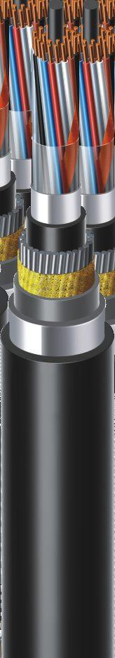
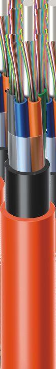

75


76
Brand-Rex Optical Cables - Universal PDC Tight Buffered Premise Distribution Cables
 Premise Distribution Cables LSZH Sheath Strength Members 900µm Tight Buffered Fibre Brand-Rex Optical Cables - Universal PDC Tight Buffered Premise Distribution Cables 4.80.00.60.90 22 460 0 2 29 34 640
Ø 1250 * 688 mm 93 kg ± 105m
 GCDE Multi Loose Tube Cables Universal Indoor / Outdoor - Corrugated Steel Tape Armor (CST) A/I-DQ(ZN)H(SR)H Full Rodent Protection 05-05-5 v7.0 Ordering Information Belden Part Numbers Fibre Description
Optical Systems Contents
 Optical Systems Optical Systems Contents Distribution Cables C Type Page 3.7 Breakout Cables T Type Page 3.9 Loose Tube Cables Unitube Page 3.14 Multi Loose Tube Page 3.18 Optical Components Pig / Patch
GORN. Central Loose Tube Cables Outdoor A-DQ(ZN)B2Y Improved Rodent Protection, 1000N Permanent Load v6.0. Ordering Information
B2Y Improved Rodent Protection, 1000N Permanent Load v6.0. Ordering Information") GORN Central Loose Tube Cables Outdoor A-DQ(ZN)BY Improved Rodent Protection, 000N Permanent Load 05--0 v6.0 Ordering Information Belden Part Numbers Fibre Description / count 4 6 8 6 4 6.5/5-OM GORN0
GORN Central Loose Tube Cables Outdoor A-DQ(ZN)BY Improved Rodent Protection, 000N Permanent Load 05--0 v6.0 Ordering Information Belden Part Numbers Fibre Description / count 4 6 8 6 4 6.5/5-OM GORN0
u n a B Optical Cables UNIFLEX CABLES LTD.
 u n a B Optical Cables UNIFLEX CABLES LTD. Established in 1981, UNIFLEX CABLES LIMITED manufactures a variety of top quality cables in India with a factory size of 15,000 sq. mts. in Umergaon (Gujarat).
Dax DX-S10121 (12F Sin ngle Mode Armoured Fiber Cable -Uni-Tube Design) Introduction:
 Introduction:") Dax DX-S10121 (12F Single Mode Armoured Fiber Cable -Uni-Tube Design) Introduction: Dax DX-S1012burial installations, providing outstanding mechanical protection and rodent resistance. is a12 core Single
Dax DX-S10121 (12F Single Mode Armoured Fiber Cable -Uni-Tube Design) Introduction: Dax DX-S1012burial installations, providing outstanding mechanical protection and rodent resistance. is a12 core Single
GAAG. Multi Loose Tube Cables Outdoor - ADSS A-DQ(ZN)2Y(T) v4.0. Ordering Information. Applications. Features & Benefits
2Y(T) v4.0. Ordering Information. Applications. Features & Benefits") GAAG Multi Loose Tube Cables Outdoor - ADSS A-DQ(ZN)Y(T) 05-04-9 v4.0 Ordering Information Belden Part Numbers Fibre Description / count 4 8 8 4 30 36 6.5/5-OM GAAG04 GAAG08 GAAG GAAG8 GAAG4 GAAG30 GAAG36
GAAG Multi Loose Tube Cables Outdoor - ADSS A-DQ(ZN)Y(T) 05-04-9 v4.0 Ordering Information Belden Part Numbers Fibre Description / count 4 8 8 4 30 36 6.5/5-OM GAAG04 GAAG08 GAAG GAAG8 GAAG4 GAAG30 GAAG36
Outdoor, Fig 8 Armored, Multi Tube
 Outdoor, Fig 8 Armored, Multi Tube Outdoor stranded Fig 8 Armored, Fiber optic cable for aerial installation. It support application such as IEEE802.3, 10G Ethernet, Gigabit Ethernet, Fast Ethernet, Ethernet,
HES HACILAR ELEKTRİK SANAYİ VE TİC.A.Ş.
 Technical Specification Revision/Date:01/02.15 By S.Erol Date : 27 February 2015 Cable Type HES Cable Product Number :, Outdoor F/O Cable :FOZZXXXSLT41DYY (ZZ: fiber type G652=SD, G657 A1 = A1, G657 A2
TECHNICAL DATA SHEET FOR Single Mode Optical Fibre Cable Direct Burial Application
 TECHNICAL DATA SHEET FOR Single Mode Optical Fibre Cable Direct Burial Application (SM 12 Fibers) Product: Single Mode Optical Fiber Cable Customer: Date: Write by: Kevin Zhou / technical engineer International
ADSS Fiber Optic Cable. DESCRIPTION core, Single-mode/Multi-mode. Version: V2.0
 ITEM MODEL NO. ADSS Fiber Optic Cable A-288-XX DESCRIPTION 2-288 core, Single-mode/Multi-mode Overview AOA-ADSS cable is ideal for installation in distribution as well as transmission environments, even
Fibre Optic Indoor/Outdoor Cable
 Volition TM Fibre Optic Indoor/Outdoor Cable Tough enough to take it. Easy to handle. The Volition Network Solutions Indoor/Outdoor Fibre Optic Cable from 3M includes horizontal and backbone cable with
Single-Armored Cables, Fibers
 Features and Benefits Fully waterblocked loose tube, gel-free design Simple access and no clean up Single-armored construction Provides additional crush and rodent protection High-strength ripcord Ease
GUXW. Mini-Breakout Cables (Distribution) Universal Indoor/ Outdoor, Steel Wire Armor (SWA) A/I-VQ(ZN)HBH Full Rodent Protection v5.
 Universal Indoor/ Outdoor, Steel Wire Armor (SWA) A/I-VQ(ZN)HBH Full Rodent Protection v5.") GUXW Mini-Breakout Cables (Distribution) Universal Indoor/ Outdoor, Steel Wire Armor (SWA) A/I-VQ(ZN)HBH Full Rodent Protection 05--0 v5.0 Ordering Information Belden Part Numbers Fibre Description / count
GUXW Mini-Breakout Cables (Distribution) Universal Indoor/ Outdoor, Steel Wire Armor (SWA) A/I-VQ(ZN)HBH Full Rodent Protection 05--0 v5.0 Ordering Information Belden Part Numbers Fibre Description / count
Medium Voltage Power Cables
 N2XSY 6/0, /20, /30 NA2XSY 6/0, /20, /30 N2XS2Y 6/0, /20, /30 NA2XS2Y 6/0, /20, /30 N2XS(F)2Y 6/0, /20, /30 NA2XS(F)2Y 6/0, /20, /30 N2XSEY 3 x 6/0 Medium Voltage Power Cables Photo: HELUKABEL Q 47 Medium
Ø560*336mm 4.25 kg 2100 ± 105m
 GUMT Mini-Breakout Cables (Distribution) Universal Indoor/ Outdoor A/I-VQ(ZN)H Standard Rodent Protection 05-0-0 v3.0 Ordering Information Belden Part Numbers Fibre Description / count 4 6 8 6 4 6.5/5-OM
OPTICAL FIBER CABLE. August 2017, New Delhi. CM/L-No
 OPTICAL FIBER CABLE August 2017, New Delhi CM/L-N. 5445164 INDEX Duct Cable Uni tube Cable... 01 Multi tube Cable... 02 Armred Cable: Uni tube armred cable... 03 Single Sheathed Armred cable... 04 Duble
ALTOS Lite Gel-Free, Single-Jacket, Single-Armored Cables, Fibers
 Features and Benefits Fully waterblocked loose tube, gel-free design Simple access and no clean up Single-armored construction Provides additional crush and rodent protection High-strength ripcord Ease
TECHNICAL DATA SHEET FOR Single Mode Optical Fibre Cable Duct Application
 TECHNICAL DATA SHEET FOR Single Mode Optical Fibre Cable Duct Application (SM 24, 36, 48, 64, 96 Fibers) Product: Single Mode Optical Fiber Cable Producer: XCOM L TD. / Bulgaira Date: August 1, 2012 Write
Ship Hybrid Cable DL 58 5 x UC1500 SS22 2x SM BendBright XS G.657.A2 6x MM MaxCap-BB-OM4
 Wiking Ship Hybrid Cable Application Hybrid cable for shipboard applications DATA ELEMENT Primary (Campus), Secondary (Riser), Tertiary (Horizontal) IEEE 802.3: 10Base-T; 100Base-T; 1000Base-T; 10GBase-T
features and benefits
 features and benefits Fully waterblocked loose tube, gel-free design Medium-density polyethylene jacket Figure-8 cable design Available in 62.5 µm, 50 µm, single-mode and hybrid versions Simple access
Optical Fiber Jelly. PBT loose tube. PE shealth. Aramid Yarn SINGLE MODE OPTICAL FIBER ITU-T REC. G.652D
 SINGLE MODE OPTICAL FIBER ITU-T REC. G.652D Product Model: GYFXTY 2~12C Our Ref: No.TS-FT201107-03-64-V1.0 GENERAL 1.1 These optical cables have excellent protection, optical transmission and mechanical
Outdoor, CCTV or CCTV, Fig 8 Armored.
 Outdoor, CCTV or CCTV, Fig 8 Armored. Outdoor stranded Fig 8 Armored, Fiber optic cable for aerial installation. It support application such as IEEE802.3, 10G Ethernet, Gigabit Ethernet, Fast Ethernet,
TECHNICAL DATASHEET FOR LOOSE TUBE OPTICAL FIBER CABLE. Air Blown Micro LC Cable
 TECHNICAL DATASHEET FOR LOOSE TUBE OPTICAL FIBER CABLE Air Blown Micro LC Cable ITU-T G.652.D 6~72F Customer : Czech Atlantis Date : Oct. 31. 2007 Author : MinLi Fu Manager : HanDong Choi Department :
Data sheet OpDAT connection cable 2x1 OS2 - bend insensitive
 Illustrations Principle diagram Page 1/7 Product specification connection cable for direct connector termination with higher robustness cable structure: I-V(ZN)HH2, duplex patch cable with additional outer
COPPER + LWL RAW CABLES
 COPPER + LWL RAW Twisted Pair Cables... 112 TV/SAT Cables... 116 Fiber Optic Raw Cables... 120 DIGITUS CAT 7 twisted pair installation cable 4x2xAWG23 S-FTP CAT 7 1000 MHz LSZH installation cable For installation
15 years of experience
 Wires and Cables 15 years of experience APS supplies standard and special copper and fiber optic cables based on its 15 years of experience in the sector, 8 of which in designing and manufacturing. Since
Datasheet Outside Plant Cable
 Outside Plant Cable Direct Buried Cable Direct buried cable can be buried directly into the ground in a trench or using a vibratory plow. Except for with great water-blocking and moisture-proof performance,
K20 & L120 LSZH Armoured F/FTP Cat6 Cables
 K20 & L120 LSZH Armoured F/FTP Cat6 Cables The cables are designed for high speed data transmissions, and are suitable for installations in cable trays or on hooks. RATP CAT6-K20 (for K20 cable) FRANCE
ekсkoм TECHNICAL DATA SHEET FOR Duct/Aerial Application kabeli.eu (SM 24 Fibers) Technical literature for Optical Fiber Cable
 Technical literature for Optical Fiber Cable") TECHNICAL DATA SHEET FOR Single Mode Optical Fibre Cable Duct/Aerial Application (SM 24 Fibers) kabeli.eu ekсkoм CATV, LAN, GEPON, SECURITY Page 1 of 6 1. Cable Construction 1.1 Cable cross-section 2.
TECHNICAL DATA SHEET FOR Single Mode Optical Fibre Cable Duct/Aerial Application (SM 24 Fibers) kabeli.eu ekсkoм CATV, LAN, GEPON, SECURITY Page 1 of 6 1. Cable Construction 1.1 Cable cross-section 2.
TwenCombi Cat-5E FTP(3x) - Coax 9 - EIBA - tube PE 5 mm
 - Coax 9 - EIBA - tube PE 5 mm") name: TKF article number: 10305 description Nr.: POE- PS- 10305 PT F F F 800 B C 1 2 3 4 5 6 7 Assembly: 1. Primary tube 5 mm 2. CAT 5 E FTP cable 3. CAT 5 E FTP cable 4. Bus cable 5. Coax 9 cable 6. Separation
name: TKF article number: 10305 description Nr.: POE- PS- 10305 PT F F F 800 B C 1 2 3 4 5 6 7 Assembly: 1. Primary tube 5 mm 2. CAT 5 E FTP cable 3. CAT 5 E FTP cable 4. Bus cable 5. Coax 9 cable 6. Separation
1.1_KV PVC insulated PVC sheathed multicore Aluminium Cable (armoured & unarmoured)
") WEST BENGAL STATE ELECTRICITY DISTRIBUTION COMPANY LIMITED (A Govt. of West Bengal Enterprise) Office of the Chief Engineer, Procurement & Contracts Department Vidyut Bhavan, 4 th. floor, Bidhannagar,
WEST BENGAL STATE ELECTRICITY DISTRIBUTION COMPANY LIMITED (A Govt. of West Bengal Enterprise) Office of the Chief Engineer, Procurement & Contracts Department Vidyut Bhavan, 4 th. floor, Bidhannagar,
List Price w.e.f. 02nd January, 2018
 w.e.f. 02nd January, 2018 HRFR/FR-LSH/HFFR/ PVC Insulated Industrial Cables Multicore Round PVC Cables Flat Three Core Industrial Cable for Sumersible use Telecom & Co-axial Cables LAN Cables CCTV Cables
GYFY-24FO Total Dry. Item Material Description PE outer sheath HDPE Nominal thickness:1.8mm
 GYFY-24FO Total Dry Filler FRP center strength member Strength member Rip cord Dielectric strength members Aramid yarns Additional strength member Filler PP Diameter same as tube Colors of tubes is : blue,
Loose Tube Cable End Preparation for Splicing For Series 11D, 1GD, 12D, 1AD, 1DD, 1CD, 11, 1G, 12, 12L, 1A, 1D, 1C, 1NY, 13, 1H, HZD and HZA
 Loose Tube Cable End Preparation for Splicing For Series 11D, 1GD, 12D, 1AD, 1DD, 1CD, 11, 1G, 12, 12L, 1A, 1D, 1C, 1NY, 13, 1H, HZD and HZA NOTE: These installation instructions have been written for
P Low Voltage Catalogue Cables Australia Powering your Project
 P +61 8 9367 8978 Low Voltage Catalogue Cables Australia Powering your Project CABLES AUSTRALIA PTY LTD LOW VOLTAGE CATALOGUE ABOUT US Cables Australia is a locally owned and operated distributor of high
TECHNICAL DATA SHEET FOR Uni-tube Single Mode Optical Fibre Cable ARMORED. (SM 2~24 Fibers)
") TECHNICAL DATA SHEET FOR Uni-tube Single Mode Optical Fibre Cable ARMORED (SM 2~24 Fibers) Product: Single Mode Optical Fiber Cable Producer: XCOM LTD. / Bulgaira Date: August 1, 2012 Write by: Petar Georgiev
TECHNICAL DATA SHEET FOR Uni-tube Single Mode Optical Fibre Cable ARMORED (SM 2~24 Fibers) Product: Single Mode Optical Fiber Cable Producer: XCOM LTD. / Bulgaira Date: August 1, 2012 Write by: Petar Georgiev
Faster. Easier. Better.
 Faster. Easier. Better. Single-Jacket, All Dielectric Loose Tube Cables Loose Tube Gel-filled buffer tube prevents water migration. All-dielectric strength member. Available as rated cable, thereby eliminating
Fiber Optic Outside Plant Cables (4-144 Fibers)
") Fiber Optic Outside Plant Cables (4-144 ) Central Tube Dielectric Cable 4-12 Fiber Water Blocking Strength Members Multi-Tube Dielectric Cable 24-216 Fiber The number of tubes changes depending on fiber
Fiber Optic Outside Plant Cables (4-144 ) Central Tube Dielectric Cable 4-12 Fiber Water Blocking Strength Members Multi-Tube Dielectric Cable 24-216 Fiber The number of tubes changes depending on fiber
Industrial Ethernet OPT cable manufactured for Petrol Forecourt Applications.
 Industrial Ethernet Petrol Forecourt Cable (Solid) 3014P24S1001 Industrial Ethernet Petrol Forecourt Cable (Solid) 3014P24S1001-10 Industrial Ethernet OPT cable manufactured for Petrol Forecourt Applications.
Y-CY-JZ flexible, CU-screened, transparent, EMC-preferred type, meter marking
 Y-CY-JZ flexible, CU-screened, transparent, EMC-preferred type, meter marking A Technical data Special PVC control cables, adapted to DINVDE0 part3 Temperature range flexing -5 C ) to +0 C fixed installation
Exhibit A Construction Project Manual and Drawings
 Exhibit A Construction Project Manual and Drawings Summary Starting the summer of 2015 TxDOT will be adding a Toll lane to Hwy 288 with fly over exits and entrances in the area of Holcombe Blvd. and Ardmore
ABOUT US ABOUT US 1 CRANE CABLES
 ABOUT US ABOUT US ÜNTEL KABLO, one of the leading cable manufacturers of Europe was established in 1972, Turkey. With almost 45 years of experience, it has been continuously developing and optimizing its
OpDAT Universalkabel 1x4 OM4 - biegeunempfindlich, Klasse. Principle diagram
 Page 1/9 Illustrations Principle diagram See enlarged drawings at the end of document Product specification installation cable U-DQ(ZN)BH universal fiber optic cable for indoors/outdoors with central or
CommunicationCables FIBER OPTICS OPGW FTTH
 CommunicationCables FIBER OPTICS OPGW FTTH Contents FIBER OPTICS 4 OPGW 34 FTTH 38 APPENDIX 54 CONNECTING THE WORLD BY TAIHAN COMMUNICATION CABLES TAIHAN has served a pivotal role in establishing communication
Connection technology for wireless communication systems
 Connection technology for wireless communication systems Rosenberger Rosenberger, founded in 1958, is a family owned company and ranks today among the top global manufacturers of high-frequency coaxial
COMMON WORK RESULTS FOR INTEGRATED AUTOMATION DESIGN AND CONSTRUCTION STANDARD
 PART 1: GENERAL 1.01 Purpose: A. This standard is intended to provide useful information to the Professional Service Provider (PSP) to establish a basis of design. The responsibility of the engineer is
MGVCL/MM/ /2082/11KV AB CABLE TECHNICAL SPECIFICATION FOR 11KV AERIAL BUNCHED CABLES FOR OVERHEAD LINES
 TECHNICAL SPECIFICATION FOR 11KV AERIAL BUNCHED CABLES FOR OVERHEAD LINES 1. Qualifying Requirement of AB Cable Manufacture/Supplier The manufacturer should have manufactured, successfully type tested
Paramount Communications Ltd., part of the Paramount Cables Group. started up as a small- scale cable unit more than 60 years ago and
 INDUSTRIAL CABLES Paramount Communications Ltd., part of the Paramount Cables Group started up as a small- scale cable unit more than 60 years ago and became one of the nation s leading cables manufacturing
Standard Monotube SAFE
 Application Mainly used in outside plant to building transitions and inter-building installations Fiber Count Single Mode Fibers Outer Diameter [mm] Cable Weight [kg/km] Design Optical Fibers Gel-filled
Data sheet OpDAT breakout cable 24x1 OM4 - bend insensitive
 Page 1/9 Illustrations Principle diagram See enlarged drawings at the end of document Product specification connection cable I-V(ZN)HH breakout cable for direct connector termination for indoors and outdoors
TECHNICAL SPECIFICATION FOR 11KV, 3C x95mm mm 2 AERIAL BUNCHED CABLES FOR OVERHEAD LINES (CROSSED LINKED POLYTHENE DRY GAS CURED)
") TECHNICAL SPECIFICATION FOR 11KV, 3C x95mm 2 + 80mm 2 AERIAL BUNCHED CABLES FOR OVERHEAD LINES (CROSSED LINKED POLYTHENE DRY GAS CURED) 1. SCOPE This specification covers requirements of, 3C x95mm 2 +
TECHNICAL SPECIFICATION FOR 11KV, 3C x95mm 2 + 80mm 2 AERIAL BUNCHED CABLES FOR OVERHEAD LINES (CROSSED LINKED POLYTHENE DRY GAS CURED) 1. SCOPE This specification covers requirements of, 3C x95mm 2 +
ENERGY CORDAFLEX (SMK) (N)SHTOEU Low Voltage Reeling Cable
 (N)SHTOEU Low Voltage Reeling Cable") ENERGY (N)SHTOEU Low Voltage Reeling Cable Technical Data Type Type designation Approvals/standards Application (N)SHTOEU-J/-O DIN VDE 0250, Part 814; VDE-Reg.-Nr. 7519; GOST R Flexible reeling cable for
ENERGY (N)SHTOEU Low Voltage Reeling Cable Technical Data Type Type designation Approvals/standards Application (N)SHTOEU-J/-O DIN VDE 0250, Part 814; VDE-Reg.-Nr. 7519; GOST R Flexible reeling cable for
JULY Standards are finally approved by the Standards High Council of Iranian Ministry of Petroleum.
 FOREWORD This Standard is intended to be used within and for Iranian Ministry of Petroleum (N.I.O.C, N.I.G.C, N.P.C., N.I.O.R.D.C. and other affiliate organizations and companies) and has been prepared
kv: medium voltage reeling cable with fibreoptics
 PROTOLO(SMK)-LWL ()TSKCGEWOEU 3,6/6 kv: medium voltage reeling cable with fibre-optics Application Flexible medium voltage reeling cable with integrated fibre-optics for the combined transmission of energy
Article number: Sheath marking ACE - TKF LTC ADSS 24x SM G.657.A1 (2x12) A-DQ(ZN)2Y {Batch} {Year} {Length}
 A-DQ(ZN)2Y {Batch} {Year} {Length}") Description 24x SM G.657.A1 (2x12) The Loose Tube Cable All Dielectric Self-Supporting (LTC ADSS) is a metalfree aerial distribution cable, with dry waterblocking and aramid yarns under the outersheath.
Description 24x SM G.657.A1 (2x12) The Loose Tube Cable All Dielectric Self-Supporting (LTC ADSS) is a metalfree aerial distribution cable, with dry waterblocking and aramid yarns under the outersheath.
VSOF-BS403A. Splice Closure for Fiber Optic Cable User Manual Rev.3
 Splice Closure for Fiber Optic Cable 1. Introduction 1.1 General VISSEM S BS403A protects fiber optic splicing point in various installation conditions such as aerial, manholes, ducts, wall and direct
INSTRUCTIONS FOR THE SAFE APPLICATION OF CABLES
 THE SAFE APPLICATIO OF CABLES The cables manufactured by S are only appropriate for the transmission of electric energy for supply and signalling purposes. First of all the valid construction and installation
Nexans Industrial Solutions PRODUCT CATALOG
 Nexans Industrial Solutions PRODUCT CATALOG i NEXANS BRINGS ENERGY TO LIFE COPPER CABLES Nexans brings energy to life through an extensive range of cables and cabling solutions that deliver increased performance
EXTREMELY LOW MAGNETIC FIELD (ELMF) XLPE INSULATED CABLES, TYPE N2XY/FR1 0.6/1 KV
 XLPE INSULATED CABLES, TYPE N2XY/FR1 0.6/1 KV") CABLE DESCRIPTION Single- or multi-phase electric cable for creating a weak external magnetic field,so as to obtain a cable wherein at last one of the conductors is assembled from two or more insulated
CABLE DESCRIPTION Single- or multi-phase electric cable for creating a weak external magnetic field,so as to obtain a cable wherein at last one of the conductors is assembled from two or more insulated
CABLES FOR MOTION CONTINUOUS-BENDING HI-FLEX ELECTRICAL CABLES TOTALTRAX TURN-KEY SYSTEMS PRE-ASSEMBLED CABLES STRAIN RELIEF DEVICES
 CABLES FOR MOTION CONTINUOUS-BENDING HI-FLEX ELECTRICAL CABLES TOTALTRAX TURN-KEY SYSTEMS PRE-ASSEMBLED CABLES STRAIN RELIEF DEVICES FOR CABLE CARRIERS EDITION 09-2012 Durable, reliable, cost-effective
MULTIMEDIA CABLE H6091ZHB
 CAVEL News MULTIMEDIA CABLE H6091ZHB MULTIMEDIA CABLE H6091ZHB Multimedia is a must in the modern way of life. Growing communication needs in any environment whether at home or the office the connection
Cores layed up around conductive filler with aramid rope in the center Rubber, special compound, mechanical properties acc.
 ()TSCGEWOEU TEAX TTS-LWL 3,6/6 kv: Application Flexible medium voltage reeling cable with integrated fibre-optics for the combined transmission of energy and data, for application under high mechanical
COAX 101. Author: Rob Wessels. Vice President of Engineering
 COAX 101 Author: Rob Wessels Vice President of Engineering Structured cable systems have very thorough standards for fiber optic and twisted pair installations. The cabling components and installed systems
14 AWG 2 AWG: 600 Volt
 INDUSTRIAL AUTOMATION & PROCESS CONTROL CABLES 18.70 600V Type MC Metal Clad and Teck-Style Cables Overview Metal Clad Interlocked PVC Outer Jacket Teck-Style PVC Outer Jacket Introduction Polyester Wrap
Data sheet MC GC1200 pro22 Cat.7A S/FTP 4P LSHF-FR, class Dca s2 d2
 Page 1/7 Illustrations Principle diagram See enlarged drawings at the end of document Product specification 10 GBit installation cable, simplex installation cable Cat.7A AWG 22 S/FTP with wires shielded
ZHONGTIAN TECHNOLOGIES CO., LTD
 ZHONGTIAN TECHNOLOGIES CO., LTD Contents Company profile...1 Quality certificates.. 2 Manufacture equipment 3 Products profile. 4 Radio Coaxial Cables 5 HHTAY-50-42 (1-5/8 ) HCTAY-50-32 (1-1/4 ) HCTAY-50-22
For information transmission at dry and moist production sites, in and under plaster, outdoors for fixed installation.
 Telecommunication and fire alarm cables For information transmission at dry and moist production sites, in and under plaster, outdoors for fixed installation. J-YY Bd 14 J-YY BMK 15 J-Y(St)Y Lg 16 J-Y(St)Y
Z EE E E Z E Z Z Z Z Z
 E A Furukawa Company Z EE E E Z E Z Z Z Z Z Optimized for Multiple Dwelling Unit (MDU) Drop and In-Home Wiring Applications EZ-Bend Optical Cables help speed and simplify indoor optical drop cable installations
Caledonian. Profibus L2 Indoor BUS CABLE. Application: Construction:
 Caledonian www.caledonian-cables.co.uk www.caledonian-cables.net Profibus L2 Indoor Application: This system cable is used to interconnect L2-BUS components. This cable is an economical solution for the
Instrumentation Cables
 around a world of cables UL INSTRUMENTATION CABLES UL THHN CABLES UL THWN CABLES Instrumentation Cables INDEX Introduction Specialty Cables 300V & 00V Instrumentation Cable Types Certificates and Standards
Data sheet MC GC1000 pro23 Cat.7 S/FTP 4P LSHF-FR 1640 ft
 Page 1/6 MC GC0 pro23 Cat.7 S/FTP 4P LSHF-FR 1640 ft 18427034141 Illustrations Principle diagram Product specification 10 GBit installation cable, simplex installation cable Cat.7 AWG 23 S/FTP with wires
EXCELLENT ELECTRICAL PERFORMANCES
 50OHMS CORRUGATED COPPER TUBE COAXIAL CABLE PRODUCT INTRODUCTION 2 Hansen's manufacturing of wide-scope 50ohms corrugated copper coaxial Cable is the fruitful result of the engineers' diligent research
To keep your family safe and protected V-Guard Wires & Cables
 The Suraksha Chakra To keep your family safe and protected V-Guard Wires & Cables Efficient Performance For over four decades V-Guard lived up to the reputation of making reliable products that were designed
GLOSSARY. Aramid Yarn Generic name for a tough synthetic material that is often used in cable construction to provide tensile strength.
 GLOSSARY A Air Spaced Cables A cable in which air is the essential dielectric material. A spirally wound synthetic filament or spacer may be used to center the conductor. Alien Crosstalk Crosstalk from
Armoured Power and Control Cables to BS7917
 1 Armoured Power and Control Cables to BS Fire Resistant, TAC. MGT. EPR. ZH. GSWB. SW, 00/00 V. Low Smoke Zero Halogen Application Armoured cables for fixed wiring in ships and offshore units where circuit
SPECIFICATION SS-140/9. 0.6/1 (1.2) kv CONTROL AND POWER UNDERGROUND CABLES WITH PVC OR XLPE INSULATION AND PVC JACKET
 kv CONTROL AND POWER UNDERGROUND CABLES WITH PVC OR XLPE INSULATION AND PVC JACKET") INDEPENDENT POWER TRANSMISSION OPERATOR S.A. TNPRD/ SUBSTATION SPECIFICATION & EQUIPMENT SECTION December 2016 SPECIFICATION 0.6/1 (1.2) kv CONTROL AND POWER UNDERGROUND CABLES WITH PVC OR XLPE INSULATION
INDEPENDENT POWER TRANSMISSION OPERATOR S.A. TNPRD/ SUBSTATION SPECIFICATION & EQUIPMENT SECTION December 2016 SPECIFICATION 0.6/1 (1.2) kv CONTROL AND POWER UNDERGROUND CABLES WITH PVC OR XLPE INSULATION
FTTH Fiber Optical Cable
 FTTH Fiber Optical Cable FTTH Drop Cables are designed to connect the fiber access point to the ONT on the home in a FTTH network. It offers an efficient and economical solution for deploying fiber in
LV AIRGUARD. P r o ble m. ife? No S. a proven, rugged product for harsh environments
 ife? No S n K P r o ble m! No? aw a proven, rugged product for harsh environments No LV AIRGUARD LV AIRGUARD Low Voltage Cables for Harsh Environments FEATURES - No Knife? No Saw? No Problem! installation
Armoured Power and Control Cables Fire Resistant
 Armoured Power and Control Cables Fire Resistant Low Smoke Zero Halogen TAC. MGT. EPR. ZH. GSWB. SW, 00/00V Application Armoured cables for fixed wiring in ships and offshore units where circuit integrity
FIBER OPTIC CABLE ASSEMBLIES
 FIBER OPTIC CABLE ASSEMBLIES QUALITY CONNECTIONS START HERE Improve the quality of your connections with America Ilsintech s line of SM & MM SC, ST, LC and MPO/MTP cable assemblies. America Ilsintech manufactures
Cables for Data Transmission in Industrial Automation. Fieldbus Cables Copper Cables Fibre Optic Cables
 Cables for Data Transmission in Industrial Automation Fieldbus Cables Copper Cables Fibre Optic Cables 2 KERPEN GmbH & Co. KG 2005 2.2006 Printing errors excepted. Subject to alteration. Contents Seite
CCW. Continuously Corrugated Welded Cable. Armored Cable for Hazardous Locations
 CCW Continuously Corrugated Welded Cable Armored Cable for Hazardous Locations CCW Servicing Industrial and Specialty Applications This catalog contains in-depth information on the most comprehensive line
Data, Network and Bus Technology
 Data, Network and Bus Technology Photo: HELUKABEL Data, Network and Bus Technology 1 Data, Network and Bus Technology The importance of information technology in our communicationsorientated world has
Content. - DDF Frame Pair Screen Cable Pair Screen Cable
 Content - 120 1.1 Ohm 120ohm DDF DDF Accessories Cables 1.1.1 2 Pair Screen Cable - DDF Frame 1.1.2 4 Pair Screen Cable - 120 Ohm 1.1.3 DDF 8 Pair Cable Screen Cable 1.1.4 16 Pair Screen Cable 1.1.5 50
Electric cables. Cranes
 Electric cables. Cranes Electric cables for mobile connections. Aristoncavi spa reserve the right to modify the data in this catalogue without notice. 01/2012 Copyright Drawings and technical descriptions
Low Voltage AIRGUARD. A proven, rugged product for harsh environments
 Low Voltage AIRGUARD A proven, rugged product for harsh environments Linking the future As the worldwide leader in the cable industry, Prysmian Group believes in the effective, efficient and sustainable
Coaxial Cables Coax Serie. HF Steckverbinder für Mobilfunk-Anwendungen. in Bulk Rings or on Cable Drums
 4.3-10 Coax Serie Coaxial Cables HF Steckverbinder für Mobilfunk-Anwendungen in Bulk Rings or on Cable Drums Coaxial Cables In addition to the wide range of coaxial connectors, Telegärtner offers suitable
Innovative Eldra Solar Cabling System SOLINQ total system for solar cabling Sustainability
 Introduction Innovative Eldra Solar Cabling System Eldra is an innovative company of international standing. A fast growing, ambitious business offering a broad range of high quality products and with
TRAXLINE CABLES FOR MOTION
 TRAXLINE CABLES FOR MOTION CONTINUOUS BENDING HI-FLEX ELECTRICAL CABLES TOTALTRAX TURN-KEY SYSTEMS TRAXLINE PRE-ASSEMBLED CABLES FOR CABLE CARRIERS EDITION 5-2016 Cost-effective, reliable, durable cables
Y O U R W A Y ENGINEERING PRODUCTS. adritec.com
 Y O U R W A Y 8 ENGINEERING PRODUCTS adritec.com Adriduct Ducting Pipes 8b2- Adrimicroduct Ducting Pipes 8b3- Adrimultiduct Ducting Pipes 8b8b1-8b4- Adrisil Ducting Pipes 8b1 ADRIDUCT Adriduct pipes are
Armoured Instrumentation Cables to BS6883
 Armoured Instrumentation Cables to BS Low Smoke Zero Halogen Pairs/Triples - Collectively Screened. TAC, EPR, SCRN, SW, GSWB, SW 0/0V Application Armoured control and instrumentation cables for fixed wiring
TONGFENG FLEXIBLE CONDUIT TONGFENG FLEXIBLE CONDUIT
 TONGFENG FLEXIBLE CONDUIT TONGFENG FLEXIBLE CONDUIT 1 COMPANY BREIF INDRODUCTION TONGFENG Products --- Your Professional Electrical Wiring Protection Solutions. As an industrial leader, the company offers
DESIGNING AND DEPLOYING SPECIAL MULTI FUNCTION FIBER OPTIC CABLES
 DESIGNING AND DEPLOYING SPECIAL MULTI FUNCTION FIBER OPTIC CABLES Heiner Ottersberg 1 NSW The Company Over 100 Years Experience in Cable Technology 1899 NSW (Norddeutsche Seekabelwerke) is founded by the
Tratos High Voltage cables
 March 2013 Tratos High Voltage cables Cables for a moving world www.tratos.eu Introduction High Voltage Cables Tratos is an international manufacturer and supplier of High & Extra High Voltage cable up
CUSTOM DESIGN COAXIAL CABLES BY SICAB
 CUSTOM DESIGN COAXIAL CABLES BY SICAB. COAX RG 58 C/U Application: Coaxial Cable 50 Ohm For indoor installation as well as in industrial areas in conduits and cable ducts, for transmission of high frequency
11-SDMS-03 REV. 02 SPECIFICATIONS FOR
 11-SDMS-03 REV. 02 SPECIFICATIONS FOR XLPE INSULATED POWER CABLES FOR RATED VOLTAGES FROM 15 KV UP TO 36 KV (U m ) This specification is property of SEC and subject to change or modification without notice
Canadian OSP Copper I-1. Table of Contents
 Canadian OSP Copper Premises Copper Table of Contents CELFIL BJBB, BJAB, BJMB and BJTB................................. I-2 Canadian ALPETH BHBB, BHAB, BKMB and BKTB.................... I-4 SEALPAP BHBF,
Selection table for flat & ribbon cables
 Just click on the products in the selection table. Click on the HELUKABEL logo at the end of the page to go back. Cables & Wires Selection table for flat & ribbon cables www.helukabel.com FLAT & RIBBON
REPORT OF PERFORMANCE TIC
 REPORT OF PERFORMANCE TIC 1580-13 OBJECT TYPE Three-core power cable 18/30(36) kv, 3x500 mm2, 2XWY(P)-FR XLPE Rated voltage, U 0/U (U m) 18/30 (36) kv Conductor material Cu Conductor cross-section 3x500