Independent 3rd Party Test Study for 10GBE. New insights for end users and consultants
|
|
|
- Francis Douglas
- 6 years ago
- Views:
Transcription
1 Independent 3rd Party Test Study for 10GBE New insights for end users and consultants
2 Content Why & Who & What & How? Qualification Testing Study Results Study Conclusions Unmasking of UTP fairytales
3 Where The Discussion Started 1. IEEE 802.3an (10GB Ethernet) is the first application standard confirming that for 10GBE STP performs better than UTP!!! 2. The reason for the limited UTP performance with 10GBE is EMC


4 What s makes 10GBE different? 10GBE is very prone to EMC issues like radiation and immunity. Why? 10 Gb/s encoding is very sensitive to signal-to noise ratio Environmental noise level gains importance The system is self disturbing ANEXT Leiterschleife Blitzstromableiter Parallel geführte Leitungen Bild 6: Elektromagnetischer Impuls (Obo Bettermann)
5 Cabling Standard Reaction 10 Gb/s Ethernet requires improved Alien Crosstalk and EMC behavior ISO/IEC amendments 1+2 define Alien Crosstalk parameters for Class E A / Cat.6 A and higher in order to cover the disturbance from the system itself ISO/IEC / EN define the MICE table specifying Environments classes Test parameters and procedures Electromagnetic Specifications cover EMC MICE environments are mandatory for cabling systems
6 MICE specification for EMC ( ISO/IEC ed. 2.1) ISO/IEC ISO/IEC
7 MICE specification Requirement Level 1 Level 2 Level 3 Mechanical rating M 1 M 2 M 3 Ingress rating I 1 I 2 I 3 Climatic C 1 C 2 C 3 Electromagnetic rating EMC E 1 E 2 E 3 Level 1 is a office environment with low impact Level 2 is a office/ enterprise building environment with medium impact Level 3 is a industrial environment with high impact Important: For some customer groups (hospitals, airports) may a combination of different classes possible ( M 1,I 2 ; C 2, E 3) )
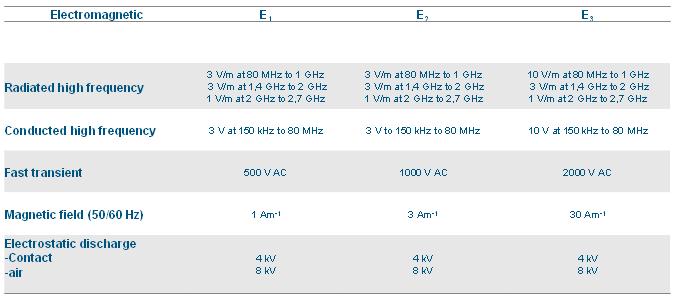
8 MICE specification for EMC
9 UTP vs. STP An Independent Study


10 Independent 3rd Party Study Unique Objectives: Qualification of Class E A systems Radiation testing Live 10GBASE-T Application testing MICE environments applications Practical testing Investigating the myth about STP systems Study conducted from 06/ /2009 at GHMT AG, Germany All tests done according international standards in an EMC chamber


11 Who is GHMT AG? Founded 1992 in Bexbach, Germany Independent test laboratory according to ISO/IEC (first lab accredited in Europe back in 2000) One of the 2 leading cabling test labs in Europe Strong expertise in Cabling & Systems EMC analysis & concepts Wireless applications

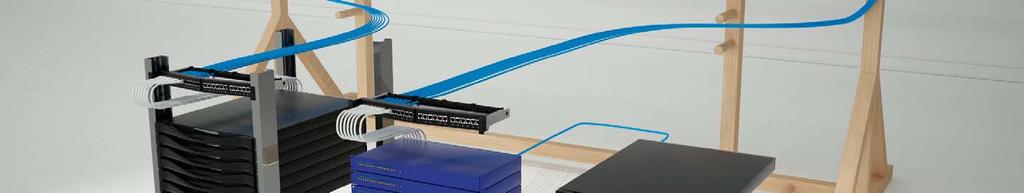
12 10GBASE-T live Test Setup
13 UTP vs. STP Qualification Testing
 S/FTP (high end)")

14 The Qualification of the Candidates 3 U/UTP systems Class E A 3 STP systems Class E A F/UTP S/FTP (standard) S/FTP (high end) The six systems were technically up to date and came from market leading companies and had to pass ISO/IEC Class EA channel
 STP Class E A Systems show much better Alien Crosstalk behaviour because of much higher coupling attenuation")
15 Qualification Results UTP Class E A systems perform well for In-Channel parameters like NEXT, RL etc. but 2 out of 3 clearly failed in achieving the Alien Crosstalk requirements (see red mark) STP Class E A Systems show much better Alien Crosstalk behaviour because of much higher coupling attenuation (see green mark) (explanation later on) Conclusion: Twist-only noise suppression is not sufficient to require 10 Gb/s system immunity Cut: Because of the insufficient ANEXT behaviour, system 00 has been excluded from the study
16 UTP vs. STP Study Results
17 EN / FCC part 15 - Radiation 10 Gb/s shows higher radiation compared to 1 Gb/s
18 EN / FCC part 15 - Radiation Comparison of both technologies STP radiates much less


19 Immunity Testing according MICE I Conducted high frequency Radiated High Frequency U/UTP systems didn t fulfill any MICE definition for HF immunity

20 Practical Test: Radiated Frequency Cabling systems have been tested with real practical disturbers ( Mobile Phones and Walkie Talkie) 10 Gb/s data traffic was monitored System 01 System 02 System 03 System 04 System 05 Phones Walkie /Talkie 10GBASE-T data transfer on U/UTP systems data has been impacted heavily or transfer stopped completely!


21 Immunity Testing according MICE II Electrostatic discharge Magnetic field Fast transient/burst immunity test U/UTP did only meet magnetic field testing and failed for electrostatic discharge and fast transients

22 Practical Test: Fluorescent Lamps

23 Practical Test: Fluorescent Lamps System 01 System 02 System 03 System 04 System 05 Fluorescence Lamp 10GBASE-T data transfer stopped completely or was heavily disturbed with U/UTP systems when distance from cabling to lamp was < 0,5 m The same effect could be observed when lamp has been switched on/off and distance lampcabling was > 0,5 m No effect on STP Cabling

24 Practical Test: Distance to Power Cable Separation distance to power cables Distances between 0-50 cm Simulation of common installation practice with burst placement on power cables

25 Practical Test: Fast Transients U/UTP systems need as a minimum 30 cm distance to power cables STP systems have no limitations
26 Data impact of separation distance What happened with my data when those effects occur?
27 UTP vs. STP Study Conclusions

28 Test Result Summary

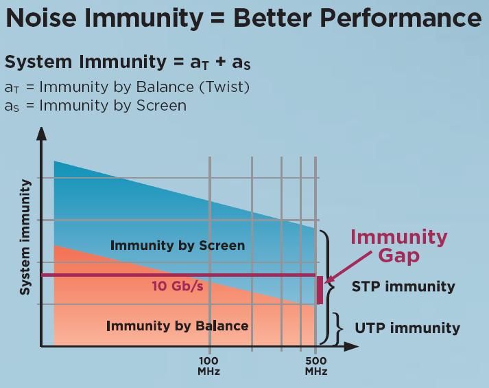
29 Noise Immunity = Better Performance
30 Coupling attenuation is key Parameter System 01 U/UTP System 02 U/UTP System 03 F/UTP System 04 S/FTP System 05 S/FTP Radiated radiofrequency EN Conducted high frequency EN Electrical fast transient/burst EN Magnetic field Immunity +++ EN Electrostatic discharge immunity test EN Coupling attenuation 45 47, (db)

31 Conclusion: STP is better For more Details:
32 UTP vs. STP Unmasking UTP Fairytales
33 Why are there UTP Fairytales? Although there are several evidences showing the superiority of STP systems, there are still a lot of concerns about STP in the market place These concerns mainly exist because of the fear-making arguments (myths; fairy tales) spread by UTP suppliers the lack of knowledge The independent study had a look at that

34 The Fairytales STP systems act like an antenna and radiate STP systems need to be grounded on both sides STP requires more complex grounding and bonding STP systems can create ground loops resulting in current on the screen STP has a lot of installation disadvantages (speed/space/screen)
35 Test Result: STP Systems act like an antenna U/UTP systems radiate much more than STP systems One reason for ANEXT issues


36 Grounding on both sides Test Result: Grounding on both sides does not improve the EMC performance of STP systems Single side grounding already exceeds the standard requirements Radiated HF Conducted HF Burst
37 STP Grounding is complex The Truth: The standards specify the mandatory use of the TN-S distribution system. Independant from UTP or STP!!! Grounding is for personal safety
38 Ground Loop Test Result: 1. TN-S with a good meshed earthing system does not lead to screen current 2. Furthermore, current on the screen does not effect data transmission System 03 System 04 System 05 Induced current on the screen according MICE 1 GB/s 0,46 A 1,74 A 2,30 A Mixed 0,48 A 1,90 A 2,40 A 10 GB/s 0,45 A 2,00 A 2,60 A System 03 System 04 System 05 1 GB/s No influence on data traffic while current on the screen Mix 10 GB/s


39 The Truth: STP Installation is complex STP is quick & easy & small mm UTP STP Cat. 6A STP cable is smaller than Cat. 6A UTP cable. Including Screen Contact
40 UTP vs. STP Overall Conclusion
41 UTP vs. STP This independent 3rd party study clearly shows The EMC parameters like ANEXT and coupling attenuation dominate the cabling channel performance for 10Gb/s Ethernet Class EA channels UTP Systems do not meet theses EMC parameters by design. Complex and time consuming installation practices are required to improve the UTP performance All arguments against STP come from UTP suppliers and are not at all based on technical research. There is no independent 3rd party test from UTP suppliers confirming their messages STP is proven to be better for 10Gb/s and more and worksbydesign
42 Questions? UTP vs. STP The future is shielded
technical bulletin UTP vs STP Shielded data cables make the grade Unshielded data cables reach the limits of their performance
 technical bulletin Data communication technology 12/2015 UTP vs STP Shielded data cables make the grade Unshielded data cables reach the limits of their performance Business Unit Datacom LEONI Kerpen GmbH
EFFECT OF SHIELDING ON CABLE RF INGRESS MEASUREMENTS LARRY COHEN
 EFFECT OF SHIELDING ON CABLE RF INGRESS MEASUREMENTS LARRY COHEN OVERVIEW Purpose: Examine the common-mode and differential RF ingress levels of 4-pair UTP, F/UTP, and F/FTP cables at an (RJ45) MDI port
Coupling attenuation and EMC considerations Draft 1.2 Comments #363 and #364
 Coupling attenuation and EMC considerations Draft 1.2 Comments #363 and #364 Dieter Schicketanz Reutlingen University Page 1 Due to measurement implications CISPR divided the frequency range in: Below
EMI AND BEL MAGNETIC ICM
 EMI AND BEL MAGNETIC ICM ABSTRACT Electromagnetic interference (EMI) in a local area network (LAN) system is a common problem that every LAN system designer faces, and it is a growing problem because the
Test Report based on DIN EN ISO/IEC 17025: 2005
 Test Report based on DIN EN ISO/IEC 1725: 25 GHMT Type Approval 2 Connector Permanent Link, Copper, Class EA according ISO/IEC 1181-1 Ed.1. Document-no: P582a-18-E This Test Report with the measurements
National Voluntary Laboratory Accreditation Program
 National Voluntary Laboratory Accreditation Program SCOPE OF ACCREDITATION TO ISO/IEC 17025:2005 Global Testing Laboratories 3029 E. Gov. John Sevier Hwy. Knoxville, TN 37914-6424 Mr. Craig Baker Phone:
Comparison of vario. ous cables & channels
 Noise Immunity Performance Analysis of Screened Cab bling Systems Comparison of vario ous cables & channels Martin Rossbach, Nexans Cabling Solutions Victoria, BC, Canada May 16, 2013 Overview Definition
Methods for Testing Impulse Noise Tolerance
 Methods for Testing Impulse Noise Tolerance May,6,2015 Larry Cohen Overview Purpose: Describe some potential test methods for impulse noise tolerance What we will cover in this presentation: Discuss need
Introduction EMC. Filter parameters. Definition of EMC / EMI. X-Capacitor. Sources of EMI. Coupling mechanism. Y-Capacitor.
 Introduction to EMC Schurter has over 75 years experience in the electronics and electrical industries, developing and manufacturing components that ensure a clean and safe supply of power. Schurter provides
Physical Test Setup for Impulse Noise Testing
 Physical Test Setup for Impulse Noise Testing Larry Cohen Overview Purpose: Use measurement results for the EM coupling (Campbell) clamp to determine a stable physical test setup for impulse noise testing.
EMC Test Report. Report Number: M030826
 Page 1 of 36 EMC Technologies Pty Ltd ABN 82 057 105 549 57 Assembly Drive Tullamarine Victoria Australia 3043 Ph: + 613 9335 3333 Fax: + 613 9338 9260 email: melb@emctech.com.au EMC Test Report Report
EMC Seminar Series All about EMC Testing and Measurement Seminar 1
 EMC Seminar Series All about EMC Testing and Measurement Seminar 1 Introduction to EMC Conducted Immunity Jeffrey Tsang Organized by : Department of Electronic Engineering 1 Basic Immunity Standards: IEC
Understanding Design, Installation, and Testing Methods That Promote Substation IED Resiliency for High-Altitude Electromagnetic Pulse Events
 Understanding Design, Installation, and Testing Methods That Promote Substation IED Resiliency for High-Altitude Electromagnetic Pulse Events Tim Minteer, Travis Mooney, Sharla Artz, and David E. Whitehead
Common Impedance Shield Coupling
 Common Impedance Shield Coupling When a coaxial cable is used at low frequencies and the shield is grounded at both ends, V R I IN S S The shield serves two functions: 1. the return conductor for the signal;
2620 Modular Measurement and Control System
 European Union (EU) Council Directive 89/336/EEC Electromagnetic Compatibility (EMC) Test Report 2620 Modular Measurement and Control System Sensoray March 31, 2006 April 4, 2006 Tests Conducted by: ElectroMagnetic
Overview of EMC Regulations and Testing. Prof. Tzong-Lin Wu Department of Electrical Engineering National Taiwan University
 Overview of EMC Regulations and Testing Prof. Tzong-Lin Wu Department of Electrical Engineering National Taiwan University What is EMC Electro-Magnetic Compatibility ( 電磁相容 ) EMC EMI (Interference) Conducted
EN61326 EMC COMPLIANCE REPORT on the LP Series Ultrasonic Transmitter Remote Amplifier and Transducer for Hawk Measurement Systems Pty Ltd
 Page 1 of 15 EMC Technologies Pty Ltd ABN 82 057 105 549 57 Assembly Drive Tullamarine Victoria Australia 3043 Ph: + 613 9335 3333 Fax: + 613 9338 9260 email: melb@emctech.com.au EN61326 EMC COMPLIANCE
Application Note # 5438
 Application Note # 5438 Electrical Noise in Motion Control Circuits 1. Origins of Electrical Noise Electrical noise appears in an electrical circuit through one of four routes: a. Impedance (Ground Loop)
Test Report based on DIN EN ISO/IEC 17025:2005
 Test Report based on DIN EN ISO/IEC 1725:25 GHMT Type Approval 2 Connector Permanent Link, Copper, Class E according ISO/IEC 1181-1 Ed.1. 217-11 Document-no: P4945b-18-E This Test Report with the measurements
National Voluntary Laboratory Accreditation Program
 National Voluntary Laboratory Accreditation Program SCOPE OF ACCREDITATION TO ISO/IEC 17025:2005 Element Materials Technology Elbridge 4939 Jordan Road Elbridge, NY 13060 Mrs. Vicki Albertson Phone: 503-844-4066
High precision measurement system for current and voltage IHC-A/B-RM01/03
 Measurement Offset-free and low-noise 16 bit data acquisition system ISA-ASIC Internal sample rate 3,500 Hz Communication Standard RS232- or RS485 interface Advantages Direct measurement on the bus bar
Saturation of Active Loop Antennas
 Saturation of Active Loop Antennas Alexander Kriz EMC and Optics Seibersdorf Laboratories 2444 Seibersdorf, Austria Abstract The EMC community is working towards shorter test distances for radiated emission
TEST REPORT. draft draft draft. TRF Originator...: Shenzhen CTL Testing Technology Co., Ltd. Master TRF...: Dated
 Shenzhen CTL Testing Technology Co., Ltd. Tel: +86-755-89486194 Fax: +86-755-26636041 TEST REPORT EN 55014-1 / EN 55014-2 Electromagnetic compatibility Requirements for household appliances, electric tools
NETWORK CONNECTIVITY SYSTEMS
 NETWORK CONNECTIVITY SYSTEMS Installation Cable KS-STP Category 7 Installation Cable Certificates 10GBaseT FTP Category 6 Installation Cable UTP Category 6 Installation Cable UTP Category 5E Installation
Impulse Noise Measurement Test Setup
 Impulse Noise Measurement Test Setup 1/27/2015 Ramin Shirani Larry Cohen Impulse Noise Problem Overview Problem: Impulse noise events in the enterprise environment may degrade the operational BER of otherwise
Electromagnetic and Radio Frequency Interference (EMI/RFI) Considerations For Nuclear Power Plant Upgrades
 Considerations For Nuclear Power Plant Upgrades") Electromagnetic and Radio Frequency Interference (EMI/RFI) Considerations For Nuclear Power Plant Upgrades November 9, 2016 Presented to: Presented by: Chad Kiger EMC Engineering Manager ckiger@ams-corp.com
Electromagnetic and Radio Frequency Interference (EMI/RFI) Considerations For Nuclear Power Plant Upgrades November 9, 2016 Presented to: Presented by: Chad Kiger EMC Engineering Manager ckiger@ams-corp.com
Alien Crosstalk Response of Augmented Category 6 Balanced Cables due to the Proximity Effect
 Alien Crosstalk esponse of Augmented Category 6 Balanced Cables due to the Proximity Effect Dr. Paulo Sérgio Marin, EE/BSc, MSc, PhD. Electrical Engineer, IT Infrastructure Consultant pmarin@paulomarin.com
PHY PMA electrical specs baseline proposal for 803.an
 PHY PMA electrical specs baseline proposal for 803.an Sandeep Gupta, Teranetics Supported by: Takeshi Nagahori, NEC electronics Vivek Telang, Vitesse Semiconductor Joseph Babanezhad, Plato Labs Yuji Kasai,
Alternative Coupling Method for Immunity Testing of Power Grid Protection Equipment
 Alternative Coupling Method for Immunity Testing of Power Grid Protection Equipment Christian Suttner*, Stefan Tenbohlen Institute of Power Transmission and High Voltage Technology (IEH), University of
EN 55015: 2013 Clause Pass. EN 55015: 2013 Clause Pass. EN 55015: 2013 Clause Pass
 Reference No.: WTD15S0730643E Page 2 of 42 1 Test Summary Test Item Conducted Disturbance at Mains Terminal, 9kHz to 30MHz Radiation electromagnetic disturbance, 9kHz to 30MHz Radiation Emission, 30MHz
9 Specifications. Specifications NOMINAL CHARACTERISTICS
 9 Specifications Specifications NOMINAL CHARACTERISTICS WARRANTED CHARACTERISTICS Nominal characteristics describe parameters and attributes that are guaranteed by design, but do not have associated tolerances.
Qualification testing of 100 ohm shielded channel, Class EA. Performed for Tyco Electronics Raychem N.V.
 We help ideas meet the real world DELTA Test Report DANAK TEST Reg. no. 19 Qualification testing of 100 ohm shielded channel, Class EA Performed for Tyco Electronics Raychem N.V. DANAK-19J1636 Project
Power Quality Issues from an EMC Point of View
 Power Quality Issues from an EMC Point of View Brian Jones BSc (Hons) C Eng MIEE MIEEE Overview What is EMC? How does it apply to power quality? The effects of equipment on power quality The effects of
Harmonizing the ANSI-C12.1(2008) EMC Tests. Harmonizing the ANSI-C12.1(2008) EMC Tests
 EMC Tests. Harmonizing the ANSI-C12.1(2008) EMC Tests") Harmonizing the ANSI-C12.1(2008) EMC Tests Subcommittee 1 (Emissions) Subcommittee 5 (Immunity) Joint Task Force on C12.1 June 17, 2013 1 The Accredited Standards Committee C63 presents Harmonizing the
Harmonizing the ANSI-C12.1(2008) EMC Tests Subcommittee 1 (Emissions) Subcommittee 5 (Immunity) Joint Task Force on C12.1 June 17, 2013 1 The Accredited Standards Committee C63 presents Harmonizing the
Bulk Current Injection instead of Radiated immunity testing, in the range from 1 MHz upto 1 GHz: Measuring results
 Immunity Testing: radiated immunity 41 Bulk Current Injection instead of Radiated immunity testing, in the range from 1 MHz upto 1 GHz: Measuring results Immunity Testing: radiated immunity 42 Bulk Current
EN :2007+A1:2011 Electromagnetic compatibility Emission standard for residential, commercial and light-industrial environments
 EMC Page 3 / 33 Test report No.: EN 61000-6-3:2007+A1:2011 Electromagnetic compatibility Emission standard for residential, commercial and light-industrial environments Date of measurement: 2013-10-16
OPEN TEM CELLS FOR EMC PRE-COMPLIANCE TESTING
 1 Introduction Radiated emission tests are typically carried out in anechoic chambers, using antennas to pick up the radiated signals. Due to bandwidth limitations, several antennas are required to cover
TEST SUMMARY Seite 2 von 27. Prüfbericht - Nr.: Test Report No HARMONICS ON AC MAINS RESULT: Passed
 17035561 001 Seite 2 von 27 Page 2 of 27 TEST SUMMARY 5.1.1 HARMONICS ON AC MAINS RESULT: Passed 5.1.2 VOLTAGE FLUCTUATIONS ON AC MAINS RESULT: Passed 5.1.3 TERMINAL CONTINUOUS DISTURBANCE VOLTAGE AT RESULT:
Electromagnetic Compliance: Pre-Compliance Test Basics October 19, 2017
 Electromagnetic Compliance: Pre-Compliance Test Basics October 19, 2017 Today s products are subjected to more standardized test requirements than ever before. These standards (UL, CE, and others) ensure
A Study of Conducted-Emission Stable Source Applied to the EMC US and EU Standards
 Fourth LACCEI International Latin American and Caribbean Conference for Engineering and Technology (LACCEI 2006) Breaking Frontiers and Barriers in Engineering: Education, Research and Practice, 21-23
EMC test report AU01+E04
 Customer: Altuflevskoye shosse,h.48,bld.1pr.1,room39 Moscow,127566 Russia EMC test report 130504-AU01+E04 This test report may not be copied or published in a part without the written authorization of
A Comparison Between MIL-STD and Commercial EMC Requirements Part 2. By Vincent W. Greb President, EMC Integrity, Inc.
 A Comparison Between MIL-STD and Commercial EMC Requirements Part 2 By Vincent W. Greb President, EMC Integrity, Inc. OVERVIEW Compare and contrast military (i.e., MIL-STD) and commercial EMC immunity
Electromagnetic Compatibility
 Electromagnetic Compatibility Introduction to EMC International Standards Measurement Setups Emissions Applications for Switch-Mode Power Supplies Filters 1 What is EMC? A system is electromagnetic compatible
OPEN TEM CELLS FOR EMC PRE-COMPLIANCE TESTING
 1 Introduction Radiated emission tests are typically carried out in anechoic chambers, using antennas to pick up the radiated signals. Due to bandwidth limitations, several antennas are required to cover
Appendix A: Specifications
 Established 1981 Advanced Test Equipment Rentals www.atecorp.com 800-404-ATEC (2832) Appendix A: Specifications This section provides a complete description of the video measurement set specifications.
American National Standard for Methods of Measurement. Frequency allocations and radio treaty matters; general rules and regulations
 IAS Accreditation Number Company Name Address TL-637 UL Korea, LTD Suwon Laboratory 218 Maeyeong-Ro, Yeongtong-Gu Suwon-Si, Gyeonggi-Do 16675 Republic of Korea Mr. YongJin Suk, Laboratory Manager Contact
An Introduction to EMC Testing (what can be done with scopes) Vincent Lascoste EMC Product Manager - RSF
 Vincent Lascoste EMC Product Manager - RSF") An Introduction to EMC Testing (what can be done with scopes) Vincent Lascoste EMC Product Manager - RSF Definition of ElectroMagnetic Compatibility (EMC) EMC is defined as: "The ability of devices and
An Introduction to EMC Testing (what can be done with scopes) Vincent Lascoste EMC Product Manager - RSF Definition of ElectroMagnetic Compatibility (EMC) EMC is defined as: "The ability of devices and
EMC Test report for LED Panel Light Models , , , , ,
 4326247.50 EMC Test report for LED Panel Light Models 000529, 000530, 000531, 000532, 000535, 000536 Guangzhou, date of issue: 2016-02-24 Author:Jazz Liang By order of Marvo Verlichting B.V. at Hoogeveen,
BIODEX MULTI- JOINT SYSTEM
 BIODEX MULTI- JOINT SYSTEM CONFORMANCE TO STANDARDS 850-000, 840-000, 852-000 FN: 18-139 5/18 Contact information Manufactured by: Biodex Medical Systems, Inc. 20 Ramsey Road, Shirley, New York, 11967-4704
TABLE OF CONTENTS. 1. General Description of EUT General Information of Test Conducted Emission Tests 7-10
 TABLE OF CONTENTS 1. General Description of EUT 3 2. General Information of Test 4-6 3.1 Conducted Emission Tests 7-10 3.2 Radiated Emission Tests 11-13 3.3 Radiated Electromagnetic disturbance Test 14-18
EMC Requirement for LED Lighting and Accessories & EMC Facilities in SIRIM
 EMC Requirement for LED Lighting and Accessories & EMC Facilities in SIRIM By: Azizul Azman Jaafar Sr. Testing Executive RF&EMCT Section Testing Services Department RFEMCT SECTION ORGANIZATION CHART HEAD
By order of ZHONGSHAN LIANGYI LIGHTING CO., LTD. at Zhongshan, China
 4317137.50 EMC Test report for LED Fixed luminaires Models LED12036-1R, LED12036-2TU, LED120363R, LED12036-4TU2, LED12036-6TR, LED12036-1R CHR, LED12036-2TU CHR, LED12036-3R CHR, LED12036-4TU2 CHR, LED12036-6TR
National Voluntary Laboratory Accreditation Program
 National Voluntary Laboratory Accreditation Program SCOPE OF ACCREDITATION TO ISO/IEC 17025:2005 VPI Laboratories, Inc. 313 W 12800 S STE 311 Draper, UT 84020 Jason Stewart Phone: 801-495-2310 Email: jasons@vpimfg.com
r(oilgln TEST REPORT 'AGREB 6 %P\l Br EMC10001 sasa Gros, B.s"{h-$ INSTITUTE EMC and Safetv Laboratorv
 r(oilgln Electrlcal Engin.erlng INSTITUTE Br. 21583EMC10001 TEST REPORT EMC and Safetv Laboratorv Page/Pages:1 /40 Test item: CT Powered Time Over-current relay Model: SIGMA XS Manufacturer: KONCAR - ELEKTRIcNI
Technical Specifications Micromedical VisualEyes 505 by Interacoustics
 VisualEyes 505 - Technical Specifications Page 0 Technical Specifications Micromedical VisualEyes 505 by Interacoustics D-0115523-B 2018/02 VisualEyes 505 - Technical Specifications Page 1 Included and
Schedule of Accreditation issued by United Kingdom Accreditation Service 2 Pine Trees, Chertsey Lane, Staines-upon-Thames, TW18 3HR, UK
 2 Pine Trees, Chertsey Lane, Staines-upon-Thames, TW18 3HR, UK Caddsdown Industrial Estate Clovelly Road Bideford Devon EX39 3DX Contact: Becky Scott Tel: +44 (0)1237 423388 Fax: +44 (0)1237 423434 E-Mail:
Research on Electromagnetic Compatibility of New Energy Vehicles
 2017 4th International Conference on Vehicle, Mechanical and Electrical Engineering (ICVMEE 2017) ISBN: 978-1-60595-477-6 Research on Electromagnetic Compatibility of New Energy Vehicles YUE ZHANG, XU
EMC TEST REPORT For MPP SOLAR INC Inverter/ Charger Model Number : PIP 4048HS
 EMC-E20130903E EMC TEST REPORT For MPP SOLAR INC Inverter/ Charger Model Number : PIP 4048HS Prepared for : MPP SOLAR INC Address : 4F, NO. 50-1, SECTION 1, HSIN-SHENG S. RD. TAIPEI, TAIWAN Prepared by
SCOPE OF ACCREDITATION TO ISO/IEC 17025:2005
 SCOPE OF ACCREDITATION TO ISO/IEC 17025:2005 NATIONAL TECHNICAL SYSTEMS (NTS) Plano Division 1701 E Plano Pkwy Suite 150 Plano, Texas 75074 Chelsie Morrow Phone: 972 509 2566 Extension 165 Chelsie.Morrow@ntscorp.com
Power Quality, Earthing And Bonding Oct $4,250 Dubai, UAE. In any of the 5 star hotels. The exact venue will be informed once finalized.
 Training Title POWER QUALITY, EARTHING AND BONDING Training Duration 5 days Training Date Power Quality, Earthing And Bonding 5 04 08 Oct $4,250 Dubai, UAE In any of the 5 star hotels. The exact venue
MEASUREMENTS OF COUPLING THROUGH BRAIDED SHIELD VIA NEW CONDUCTED IMMUNITY TECH- NIQUE
 Progress In Electromagnetics Research C, Vol. 11, 61 68, 2009 MEASUREMENTS OF COUPLING THROUGH BRAIDED SHIELD VIA NEW CONDUCTED IMMUNITY TECH- NIQUE M. Ghassempouri College of Electrical Engineering Iran
ECE 528 Understanding Power Quality
 ECE 528 Understanding Power Quality http://www.ece.uidaho.edu/ee/power/ece528/ Paul Ortmann portmann@uidaho.edu 208-733-7972 (voice) Lecture 41 1 Today Wiring for communications Decibels Coupling Avoiding
LS200 TEST DATA IEC61000 SERIES
 TEST DATA IEC61000 SERIES DWG. No. PA607-58-01 APPD CHK DWG TDK-Lambda INDEX LS200 PAGE 1. Electrostatic Discharge Immunity Test (IEC61000-4-2) R-1 2. Radiated Radio-Frequency Electromagnetic Field Immunity
EN 55022: 2010+AC:2011 Clause 6.1 Pass. Harmonic Current EN :2006+A1:2009+A2:2009 Class A N/A
 Reference No.: WT12106773-N-S-E Page 2 of 33 1 Test Summary Test Item Mains Terminal Disturbance Voltage, 150KHz to 30MHz Radiation Emission, 30MHz to 1000MHz EMISSION Test Standard Class / Severity Result
CE Testing Results and Explanation
 1500 West University Parkway Sarasota, Florida 34243 Phone 941-362-1200 Telefax 941-362-1290 www.sunhydraulics.com CE Testing Results and Explanation This article summarizes the electromagnetic compatibility
Electromagnetic compatibility Guidance and manufacturer s declaration DIN EN :2007 (IEC :2007)
") Compressor set Equipment Under Test (EUT) Type 028 Type 047 Type 052 Type 085 Electromagnetic compatibility Guidance and manufacturer s declaration DIN EN 60601-1-2:2007 (IEC 60601-1-2:2007) 2017 PARI
Compressor set Equipment Under Test (EUT) Type 028 Type 047 Type 052 Type 085 Electromagnetic compatibility Guidance and manufacturer s declaration DIN EN 60601-1-2:2007 (IEC 60601-1-2:2007) 2017 PARI
10GBASE-T T Tutorial. SolarFlare Communications IEEE Kauai, Hawaii. November 11, 2002
 10GBASE-T T Tutorial IEEE 802.3 Kauai, Hawaii November 11, 2002 Communications Communications 10GBASE-T IEEE Tutorial, 11/11/2002 1 Agenda Introduction, Cabling & Challenges - George Zimmerman, Ph.D. CEO
Guidance and Declaration - Electromagnetic Compatibility (EMC) for the Delfi PTS ii Portable Tourniquet System
 for the Delfi PTS ii Portable Tourniquet System") Guidance and Declaration - Electromagnetic Compatibility (EMC) for the Delfi TS ii ortable Tourniquet System Guidance and manufacturer s declaration electromagnetic emissions The TS ii ortable Tourniquet
Guidance and Declaration - Electromagnetic Compatibility (EMC) for the Delfi TS ii ortable Tourniquet System Guidance and manufacturer s declaration electromagnetic emissions The TS ii ortable Tourniquet
Laboratory Accreditation Programmes
 Laboratory Address PO Box 68307, Newton, Auckland, 1145 47 Mackelvie Street, Grey Lynn, Auckland, 1021 Telephone 09 360-0862 Fax 09 360-0861 URL Authorised Representative Client No. 2218 Programme Accreditation
Coupling unit CM-IVN For expansion of the insulation monitoring relay CM-IWN.x measuring range up to U n = 690 V AC and 1000 V DC
 Data sheet Coupling unit CM-IVN For expansion of the insulation monitoring relay CM-IWN.x measuring range up to U n = 690 V AC and 1000 V DC The CM-IVN serves to extend the measuring range of the insulation
INSTALLATION MANUAL. Model: Smart Analyzer Manufacturer: Smart Impulse. Power meter with consumption breakdown by use 03/12/13
 INSTALLATION MANUAL Model: Smart Analyzer Manufacturer: Smart Impulse Power meter with consumption breakdown by use 03/12/13 Table of contents Table of contents... 2 1. Introduction... 3 2. Installation
In this section of my blog, I will be discussing different transmission methods and why those particular methods are used in particular situations:
 In this section of my blog, I will be discussing different transmission methods and why those particular methods are used in particular situations: Transmission Methods are a variety of different methods
This annex is valid from: to Replaces annex dated: Location(s) where activities are performed under accreditation
 where activities are performed under accreditation") Location(s) where activities are performed under accreditation Head Office Vijzelmolenlaan 5 & 7 3447 GX oerden The Netherlands Location Abbreviation/ location code Vijzelmolenlaan 5 & 7 3447 GX oerden
Location(s) where activities are performed under accreditation Head Office Vijzelmolenlaan 5 & 7 3447 GX oerden The Netherlands Location Abbreviation/ location code Vijzelmolenlaan 5 & 7 3447 GX oerden
Noise considerations for RTPGE objectives. Gavin Parnaby IEEE RTPGE Study Group Geneva September 2012
 Noise considerations for RTPGE objectives Gavin Parnaby IEEE 802.3 RTPGE Study Group Geneva September 2012 Preface Close to moving out of study group phase Presentations have been made on automotive requirements
Accredited calibration of field strength meters
 Accredited calibration of field strength meters Calibration laboratory accredited in accordance with DIN EN ISO/IEC 17025:2005 by the Deutsche Akkreditierungsstelle (DAkkS) Application oriented calibration
Holiday Detector mod. 284/35KV
 Holiday Detector mod. 284/35KV Telemagnetica S.r.l. Via Teocrito, 36-20128 Milan - Italy Tel: +39-022552900 - Fax: +39-022553097 e-mail: info@telemagnetica.com - http: January 2013 BR-284-35KV-ENG-00 Pag.
Coupling unit CM-IVN For expansion of the insulation monitoring relay CM-IWN.x measuring range up to U n = 690 V AC and 1000 V DC
 Data sheet Coupling unit CM-IVN For expansion of the insulation monitoring relay CM-IWN.x measuring range up to U n = 690 V AC and 1000 V DC The CM-IVN serves to extend the measuring range of the insulation
Federal Institute of Metrology METAS Introduction to emc Einführung in die EMV
 Federal Institute of Metrology METAS Einführung in die EMV EMV-Fachtagung, 21. Januar 2014 1 1.1 How emc is important! A West GermanTornado fighter crashed after flying too close to a powerful transmitter.
R&TTE Testing For EU Market
 R&TTE Testing For EU Market Derek Y W Leung IEEE Hong Kong EMC Chapter Committee Member 1 R&TTE Directive 1999/5/EC Directive 1999/5/EC of the European Parliament and of the Council of 9 March 1999 on
10GBASE-T Transmitter Key Specifications
 10GBASE-T Transmitter Key Specifications Sandeep Gupta, Jose Tellado Teranetics, Santa Clara, CA sgupta@teranetics.com 5/19/2004 1 1000BASE-T Transmitter spec. overview Differential voltage at MDI output
BEA s digital inductive single loop solution
 BEA s digital inductive single loop solution Matrix2-S With more standard features than any other loop detector on the market, the Matrix2-S has the flexibility, compatibility and performance to maximize
Modem 9600 baud 500FSD11 EDS500 series - FSK modems
 Data sheet Modem 9600 baud 500FSD11 EDS500 series - FSK modems Voice frequency telegraphy device (VFT) Transparent up to 9600 baud Can be connected to 23WT24 DIN rail mounted 24...60 V DC supply voltage
n Proper pin termination at each end n Continuity to the remote end n Shorts between any two or more conductors n Transposed pairs: n Crossed pairs.
 INTRODUCTION Structured Cabling or data cabling (also known Local Area Network or LAN Cabling) is increasing in its deployment for business, commercial and residential use to carry signaling for networks
This annex is valid from: to Replaces annex dated: Locations where activities are performed under accreditation
 Annex to declaration accreditation (scope accreditation) Locations where activities are performed under accreditation Location Abbreviation/ location code Head Location Vijzelmolenlaan 5 & 7 3447 GX oerden
TEST REPORT... 1 CONTENT...
 CONTENT TEST REPORT... 1 CONTENT... 2 1 TEST RESULTS SUMMARY... 3 2 EMF RESULTS CONCLUSION... 4 3 LABORATORY MEASUREMENTS... 5 4 EMI TEST... 6 4.1 DISTURBANCE VOLTAGE ON MAINS TERMINALS ( KHZ- MHZ)...
OPSJ1900 J1900 Open Pluggable Specification Products
 J1900 Open Pluggable Specification Products Extensive range of computational power and letting you choose between diffrent operating systems, Finlux always offers you the most suitable choice that will
EMC standards. Presented by: Karim Loukil & Kaïs Siala
 Training Course on Conformity and Interoperability on Type Approval testing for Mobile Terminals, Homologation Procedures and Market Surveillance, Tunis-Tunisia, from 20 to 24 April 2015 EMC standards
Introduction to Electromagnetic Compatibility (EMC) for Open Day 18 September 2013 Presentation by Pete Dorey. TÜV Product Service
 for Open Day 18 September 2013 Presentation by Pete Dorey. TÜV Product Service") Introduction to Electromagnetic Compatibility (EMC) for Open Day 18 September 2013 Presentation by Pete Dorey 1 Content Overview of Electromagnetic Compatibility (EMC) EMC Design EMC Examples EMC Directive
Introduction to Electromagnetic Compatibility (EMC) for Open Day 18 September 2013 Presentation by Pete Dorey 1 Content Overview of Electromagnetic Compatibility (EMC) EMC Design EMC Examples EMC Directive
Ackrediteringens omfattning/scope of accreditation
 Bilaga/Anne 2G EMC GENERIC STANDARDS European std International std Title Fleible scope EN 61000-6-1:2007 IEC 61000-6-1:2005 Electromagnetic compatibility (EMC) - Part 6-1: Generic standards - Immunity
Electromagnetic Compatibility ( EMC )
") Electromagnetic Compatibility ( EMC ) Introduction EMC Testing 1-2 -1 Agenda System Radiated Interference Test System Conducted Interference Test 1-2 -2 System Radiated Interference Test Open-Area Test
Electromagnetic Compatibility ( EMC ) Introduction EMC Testing 1-2 -1 Agenda System Radiated Interference Test System Conducted Interference Test 1-2 -2 System Radiated Interference Test Open-Area Test
A) Documentation Page(s) Test report 1-17 Directory 2 Test Regulations 3 General Remarks and Summary 17 Test-setups (Photos) 18-23
 Documentation Page(s) Test report 1-17 Directory 2 Test Regulations 3 General Remarks and Summary 17 Test-setups (Photos) 18-23") D I R E C T O R Y A) Documentation Page(s) Test report 1-17 Directory 2 Test Regulations 3 General Remarks and Summary 17 Test-setups (Photos) 18-23 B) Test data: Immunity against Electrostatic discharge
D I R E C T O R Y A) Documentation Page(s) Test report 1-17 Directory 2 Test Regulations 3 General Remarks and Summary 17 Test-setups (Photos) 18-23 B) Test data: Immunity against Electrostatic discharge
TABLE OF CONTENTS. Report No.: SH E03 1. TEST RESULT CERTIFICATION...3
 TABLE OF CONTENTS 1. TEST RESULT CERTIFICATION...3 2. GENERAL INFORMATION...4 2.1 Equipment under Test (EUT) Description...4 2.2 Test Standards and Results...5 2.3 Facilities and Accreditations...6 2.3.1
Alternative Radiated Emission Test Methods Progress Achieved in IND60 Project
 Alternative Radiated Emission Test Methods Progress Achieved in IND60 Project Project EMRP IND60: Improved EMC test methods in industrial environments Mohammed Salhi 05-09 September 2016 Wroclaw, Poland
Declaration of Conformity.
 Declaration of Conformity. Type of equipment: Brand Name /Trade Mark: Type designation /model: Variant Model Name: Applicant: CAMERA HOUSING SAMSUNG TECHWIN CO., LTD. SCX-FH200B SHB-4200 SAMSUNG TECHWIN
EMC TEST REPORT for LEDELS LIGHTING CO., LTD. LED module Model No. : LL-F12T4815X6B
 Page 1 of 27 Report No. R011412016E-1 EMC TEST REPORT for LEDELS LIGHTING CO., LTD LED module Model No. : LL-F12T4815X6B Prepared for : LEDELS LIGHTING CO., LTD Address : 5F, Block C, Mingjinhai Ind. Park,
TEST SUMMARY Seite 2 von 19. Prüfbericht - Nr.: Test Report No.:
 10050333 001 Seite 2 von 19 Page 2 of 19 TEST SUMMARY 5.1 CONDUCTED EMISSION PER SECTION 15.107, FCC 47 CFR PART 15 SUBPART B RESULT: Pass 5.2 RADIATED EMISSION PER SECTION 15.109, FCC 47 CFR PART 15 SUBPART
Accr. 002-Test EN-ISO (2005)
") Electromagnetic compatibility LAB > Examination of compliance with EMC standards > Measurement of radio-disturbances > Immunity tests > 2004/108/EC EMC Directive > CE Marking > Measurement of electromagnetic
Electromagnetic compatibility LAB > Examination of compliance with EMC standards > Measurement of radio-disturbances > Immunity tests > 2004/108/EC EMC Directive > CE Marking > Measurement of electromagnetic
Technical information Release 07/2010. Cable management systems for improvement of EMC
 Technical information Release 07/2010 Cable management systems for improvement of EMC Definition of electromagnetic compatibility (EMC) In recent years, the use of electronic circuits has increased continually.
Chrysler EMC/Electrical Laboratory DC-11224/5 & DC Self-Assessment
 CHRSLER CORPORATION Laboratory Testing Capability Self-Assessment Form: Revision 2.0 Lab Approval Category Code: J-1 Change: August 1, 2007 1.0 GENERAL Chrysler EMC/Electrical Laboratory DC-11224/5 & DC-10615
via cable Route of signal interferences Shielding against radiation
 1. Introduction In the vicinity of electronics and control systems, there is often high powered equipment and cabling. In these situations it is possible that electronic circuits can be affected by these