Technical Description
|
|
|
- Rosaline McCoy
- 6 years ago
- Views:
Transcription
1 Z _englischeBeschr_Mai2016.doc Status: Page: 1/31 Technical Description Leak detector conductive electrode type ELH..., Conductive plate electrode type EP..., Measuring transducer types ER , ER-110, ER , XR-..., ET-4... and OAA-300, OAA Construction of the Leak Prevention Device The leak prevention device consists of a leak detector (1) and a separate measuring transducer (2) (ER ; ER-110, ER-145..; ER ; ER , XR-...) or a leak detector (1) with an integrated measuring transducer (2) (ET-45..., ET-460, ET-47..., ET- 48..), which supplies a binary switching signal at the outlet. This binary signal can be supplied directly or with the aid of a signal amplifier (4) to the signalling device (5a) or the control unit (5b) with its actuator (5c). In the leak prevention devices consisting of the level sensor (1) with a downstream alarm signal (OAA-300 and OAA-500 ), the warning device (5a) is integrated as an added feature in the measuring transducer (2). The leak prevention system components that have not been tested, such as the signal amplifier (4), the warning device (5a) or the control unit (5b) with the actuator (5c), must meet the requirements of sections 3 and 4 of the approval principles for overfill protection systems (ZGÜS). 1.1 Schematic Configuration of the Leak Prevention Device Leak Prevention Device (1), Separate Measuring Transducer (2) L E E (1) (2) (4) (5a) (1) Leak detector (electrode) (2) Measuring transducer (The measuring transducers in series ET-4xx are integrated in the probes) (4) Signal amplifier (5a) Warning device (with horn and signal light)
2 Z _englischeBeschr_Mai2016.doc Status: Page: 2/ Leak Prevention Device (1) with Integrated Measuring Transducer (2) (5a) L E E (1) (2) (4) (5b) (5c) (1) Level sensor (cond. electrode) (2) Measuring transducer integrated (4) Signal amplifier (5a) Warning device (with horn and signal light) (5b) Control unit (5c) Actuator Leak Prevention Device (1), Separate Measuring Transducer (2) with Integrated Warning device (5a) (5a) L E E (1) (2) (4) (5b) (1) Level sensor (cond. electrode) (2) Measuring transducer integrated (4) Signal amplifier (5a) Warning device (with horn and signal light) (5b) Control unit (5c) Actuator (5c)
3 Z _englischeBeschr_Mai2016.doc Status: Page: 3/ Functional Description The measuring transducers supply a measuring voltage which allows an operating current to flow in the measuring circuit. The operating current is limited by a resistance in the connected leak detector. A significant reduction in this operating current due to a line interruption is recognised by the measuring transducer, indicated on the LEDs and the output relay is switched into the alarm position. The current flowing in the measuring circuit increases if the electrodes become moist due to a rise in the level of leakage. This is recognised by the measuring transducer, indicated on the LEDs and the output relay is switched to the alarm setting. If the degree of leakage drops and the electrodes are no longer wet, the LEDs and the output relay are reset to the basic position immediately in the measuring transducers without a button. In the measuring transducers with a button alarm saving the button must be pressed to cancel the alarm. The measuring transducers must be adjusted to suit the conductivity of the fluid being monitored. The setting is done at the potentiometer on the front of the measuring transducers or at the DIP switches on the printed circuit board. The measuring transducer works in quiescent current mode, the alarm setting of the output contacts corresponds to that in a device disconnected from power. For that reason, not only will a line interruption or a filling alarm lead to an alarm signal, an operating voltage failure in the measuring transducer will do so too. For applications in hazardous (potentially explosive) areas only the devices approved for such areas may be used. Furthermore, the relevant regulations for setting up and operating electrical systems must be observed). Signalling Table ER-107 / ER-110 / ER-145 / ET-48x ER-117/217/XR-.. LED green red green yellow red Mains OFF Operation Line fault Filling alarm ET- 440 ET- 45x / ET- 46x / ET- 472 ET- 470 LED green yellow E1 green green red Mains OFF Operation Line fault Filling alarm LED off:, LED on:, LED flashing ca. 1 Hz
4 Z _englischeBeschr_Mai2016.doc Status: Page: 4/31 Signalling Table OAA Line fault red On Line fault acknowledged red Off Fault rectified green Off Rectified fault acknowledged green Off Filling alarm, leakage alarm yellow On Filling alarm, leakage alarm yellow Off acknowledged Fault rectified green Off Rectified fault acknowledged green Off LED off:, LED on:, LED flashing:. Signalling Table OAA LED Channel LED, 3-colour Groupalarm Horn Mains OFF or no sensor Off connected Operation, sensor connected green Off LED Channel LED, 3-colour Groupalarm Horn Mains OFF or no sensor Off connected Operation, sensor connected green Off Line fault red On Line fault acknowledged red Off Filling alarm, leakage alarm yellow On Filling alarm, leakage alarm yellow Off acknowledged Fault rectified green Off Rectified fault acknowledged green Off LED off:, LED on:, LED flashing:.
5 Z _englischeBeschr_Mai2016.doc Status: Page: 5/ Type code Leakage Detector Hanging Electrode Basic designation Rod material _ = Stainless steel (1.4571) _ = Hastelloy B _ = Hastelloy C _ = Titanium _ = Tantalum _ = Monel _ = Vitreous carbon Connection _ = wihout socket _ = socket mounted with screw connection _ = wihout socket, with screw connection _ = plug connection Cable length _ = Length in m Cable break resistance _ = 22 kohm _ = 100 kohm Diameter of probe body _ = 40 mm _ = 25 mm _ = 15 mm Connection threading _ = G 1.1/2 _ = G 1 _ = G 1.1/4 _ = G 2 _ = G 2.3/4" Material of the probe body _ = PE _ = PP _ = PVC _ = PVDF _ = PE-EL (electrically conductive) _ = PP-EL (electrically conductive) _ = PVC-EL (electrically conductive) Cable material _ = TPK _ = FEP _ = YM2 Option _ = Electronic part ELH Interface measurement Basic version SCHWE with ELH ELH (see 1.3.1)
6 Z _englischeBeschr_Mai2016.doc Status: Page: 6/ Leakage Detector Plate Electrode EP Basic designation Material of the probe body _ = PP _ = PE _ = PVC _ = PT _ = PVDF _ = PE-EL (electrically conductive) _ = PP-EL (electrically conductive) _ = PVC-EL (electrically conductive) Rod material _ = Stainless steel (1.4571) _ = Hastelloy B _ = Hastelloy C _ = Titanium _ = Tantalum _ = Monel _ = Vitreous carbon Cable length _ = Length in m Cable break resistance _ = no resistance _ = 22 kohm _ = 100 kohm Cable material _ = TPK _ = FEP _ = YM2 Option _ = Electronic part Pipe monitoring Basic designation Version L = leak detector double pipe T = protection against dry running filling line Connection without indication _ = PVC sleeve nut G 1.1/4 Tube material and connection _ = PVC _ = PE Rod material _ = Edelstahl _ = Hastelloy B _ = Hastelloy C _ = Titan _ = Tantal EFL accessories Basic designation ZUB Connection _ = PVC gluing connection for tube d=32 mm _ = PVC G ½ _ = PE weld in part for tube d=40 mm _ = PE G ½ Additive _ = without ball valve _ = with ball valve EF2 Electronics part ET473L = leak detector double pipe ET473T = protection against dry running fillling line
7 Z _englischeBeschr_Mai2016.doc Status: Page: 7/ Measuring Transducer ER Basic designation ER 107 Type (1-channel) Housing _ = LDG-A12 with screw-type terminals _ = ME, with spring-clamp terminals, plugged-in _ = ME, with screw-type terminals, plugged-in Switching delay _ = fixed, approx. 0.3 sec. Sensitivity range _ = kohm _ = kohm Supply voltage _ = 24 VDC _ = 24 VAC _ = 42 VAC _ = 48 VAC _ = 127 VAC _ = 230 VAC _ = 240 VAC _ = 115 VAC Type of construction _ = 22.5 mm mounting rail = 19 board version Measuring Transducer ER Basic designation Type Switching delay _ = fixed _ = adjustable ER 110 Sensitivity range _ = fixed _ = adjustable Supply voltage _ = 230 V AC _ = 24 V DC Option _ = WHG
8 Z _englischeBeschr_Mai2016.doc Status: Page: 8/ Measuring Transducer ER Basic designation Type (1-channel) Housing _ = ME, with screw-type terminals Switching delay _ = fixed approx. 0.5 sec. Sensitivity range _ = kohm Supply voltage _ = 24 VDC _ = 24 VAC _ = 42 VAC _ = 48 VAC _ = 127 VAC _ = 230 VAC _ = 240 VAC _ = 115 VAC Button _ = without button _ = with button ER Measuring Transducer ER and ER resp. Basic designation Channels _ = Channels Type Housing _ = ME, with spring-clamp terminals, plugged-in _ = ME, with screw-type terminals, plugged-in Switching delay _ = fixed approx. 0.3 sec. Sensitivity range _ = kohm _ = kohm Supply range _ = 24 VDC _ = 24 VAC _ = 42 VAC _ = 48 VAC _ = 127 VAC _ = 230 VAC _ = 240 VAC _ = 115 VAC Type of construction _ = 22.5 mm mounting rail = 19 board version ER 17
9 Z _englischeBeschr_Mai2016.doc Status: Page: 9/ Measuring Transducer XR-... Basic designation Number of channels 1 = 1 channel 2 = 2 channels Option 2 = WHG Housing B = Plugged clamps (for screwing) C = Plugged clamps (spring force) Output 1 = 1 change-over contact (2 channel version) 2 = 2 change-over contacts (1 channel version) Switching delay 0 = 0.5 s Sensitivity range 1 = kohm 2 = kohm 3 = 0,2.. 3 kohm Supply voltage 0 = 24 V DC 6 = 230 V DC 9 = V AC/DC multi voltage power supply unit Construction form _ = 22.5 mm mounting rail K = 19 board version B = Bus connection / option at 24 V DC XR Measuring Transducer OAA with warning device Basic designation Version _ = 2-channel _ = 4-channel Supply voltage _ = 24 VDC _ = 24 VAC _ = 42 VAC _ = 48 VAC _ = 127 VAC _ = 230 VAC _ = 240 VAC _ = 115 VAC OAA-300-
10 Z _englischeBeschr_Mai2016.doc Status: Page: 10/ Measuring Transducer OAA with warning device Basic designation Type Execution A1 = wall A2 = enclosure Addition _ = without Horn _ = with Horn OAA Dimension Sheets for the Leakage Detector (1) Leakage electrode hanging ELH... * Da Ds H 40 mm 6 bzw. 4 mm 140mm 25mm 6 bzw. 4 mm 140mm 15mm 3mm 140mm ** version for SCHWE: rod length 50mm L: Cable length ~ 38 ~ 55 ST Plate electrode EP... ** L: Cable length
11 Z _englischeBeschr_Mai2016.doc Status: Page: 11/ Pipeline monitoring PVC union nut G 1.1/4 Hirschmann connector Type GSP 313 PVC union nut G 1.1/4 Hirschmann connector Type GSP 313 EF2L PTFE coated * EF2T PVC ball valve * d=40 PE d=32 PVC Alternatively to d=40 or d=32: G ½ connection Accessories for EF2L or EF2T
12 Z _englischeBeschr_Mai2016.doc Status: Page: 12/ Schwimmerelektrode SCHWE 90 (mit Elektrode ELH)
13 Z _englischeBeschr_Mai2016.doc Status: Page: 13/ Dimension Sheets for the Measuring Transducer (2) Measuring Transducer Electrode Relay ER-145/A/EX..; ER-107/B...; ER and ER-217..; XR-.. ER-107/B.. (1-Channel) ER (1-channel) ER-217../XR-.. (2-chanel) ER-145/A/EX A1 A A1 A A1 A2 PWR ERR ER-107/B E0 E1 ERR OUT PWR ER-117 E0 E1 E2 ERR OUT PWR ER-217 E0 E1 E2 E3 E4 E * ERR = lead fault, OUT = electrode wet, PWR = mains Housing dimensions: Height 120 mm x Width 22.5 mm x Depth 100 mm
14 Z _englischeBeschr_Mai2016.doc Status: Page: 14/ Measuring Transducer Electrode Relay ER-107/S.. - A2 A1 E1 - E0 ER- 107/S Alarm Betrieb Measuring Transducer Electrode Relay ER-107/...K Betrieb Alarm Empfindlichkeit Elektrodenrelais ER-107/K A2 (-) c a A1(+) E1 E Betrieb = operation / Empfindlichkeit = sensitivity / Elektrodenrelais = electrode relay
15 Z _englischeBeschr_Mai2016.doc Status: Page: 15/ Measuring Transducer Electrode Relay ER-117/...K I ER-117 I ERR OUT PWR QUIT K3 E1 E0 NC NO A1(+) A2(-) PE NC1 COM C A * ERR = lead fault, OUT = Electrode wet, PWR = mains Measuring transducer electrode relay ER-217/...K II I II ER-217 ERR I ERR OUT PWR QUIT K3 K4 E1 E0 NC NO NC NO A1(+) A2(-) PE NC1 COM COM E3 E0 C A * ERR = lead fault, OUT = electrode wet, PWR = mains
16 Z _englischeBeschr_Mai2016.doc Status: Page: 16/ Measuring Transducer Electrode Relay ER housing dimensions: 120 mm x 80 mm x 57 mm Alarm detector OAA-300 housing dimensions: 170 mm x 165 mm x 85 mm

17 Z _englischeBeschr_Mai2016.doc Status: Page: 17/ Alarm detector OAA-500 housing dimensions: 137 mm x 186 mm (without cable glands) x 103 mm housing dimensions: 86 mm x 70 mm x 60 mm

18 Z _englischeBeschr_Mai2016.doc Status: Page: 18/ Electronic Parts ET-4.. ET- 450 ET- 451 ET V V 64 mm ET mm ET- 480
19 Z _englischeBeschr_Mai2016.doc Status: Page: 19/ Technical Data Leak detector (1) Plate electrode EP... Material of the non-metallic parts that are in contact Suitable plastic with media Type of conductor Suitable conductor material Conductor length on request Operating temperature / operating pressure atmospheric conditions Level of resistance for line monitoring: 22kΩ / 100kΩ depending on the version Material of the metallic parts (sensing rods) Stainless steel (1.4571) / tantalum / glassy carbon Degree of protection in conformance to EN IP Hanging Electrode ELH... Material of the non-metallic parts that are in contact with the media 40mm: PP, PE, PVC, PVDF 25mm: PP, PE 15mm: PP, PE, PVC Screw connection: PVDF Suitable conductor material Type of conductor Conductor length on request (standard 3m) Operating temperature / operating pressure atmospheric conditions Level of resistance for the line monitoring: 22kΩ / 100kΩ depending on the version Material of the conductive parts (sensing rods) Stainless steel (1.4571), Hastelloy B, Hastelloy C, titanium, tantalum, glassy carbon or suchlike Degree of protection acc. to EN IP 68 Addition Lightning Protection Device BL-100 Housing aluminium Degree of protection acc. to EN IP 65 Ambient temperature C Signal conductors max. 4 mm² single-wire max. 2.5 mm² fine-wire Equipotential bonding outside: max. 2 x 4 mm²; min. 4 mm²; Equipotential bonding inside: 2 x 4 mm² Pipeline monitoring Integrated electronics V DC Electr. connection Hirschmann connector GSP 313 Rod material , HB, HC, TI, TA, KO Parts in contact with media PE and PVC Mech. connection a) union nut G 1.1/4 b) sleeve welding d=40 or d=32 org ½ shut-off valve (PVC) d=20 Ambient temperature C
20 Z _englischeBeschr_Mai2016.doc Status: Page: 20/ Technical Data for the Measuring Transducer (2): Type Mains supply: Rated voltage Power consumption Output: Output contacts Switching voltage Switching current Switching voltage (terminals 11, 12, 14) Switching current (terminals 11, 12, 14) Switching capacity Input: Open-circuit voltage Short-circuit voltage Operating temper. Degree of prot. acc. to EN ET 45., -46., ( ) VDC 1 W 1 NC-contact max. 35 VAC / VDC max. 0,12 AAC / ADC < 10 V < 5 ma C IP 00 ET ( ) VDC 1 W 1 change-over cont., 1 NC-cont., common root max. 35 VAC / VDC max. 0,12 AAC / ADC max. 250 VAC max. 150 VDC max. 5 A max. 500 VA / W (30VDC) 10 W < 10 VAC < 5 ma C IP 00 ET ( ) VDC 1 W NC-contact or NO-contact max. 24 VDC 200 ma DC max. 5 W < 10 V < 5 ma C IP 00 ET V AC/DC 1 W 2 floating changeover contacts max. 250 VAC/DC max. 5 A max. 500 VA / W (30VDC) 10 W < 10 V < 5 ma C IP 00
21 Z _englischeBeschr_Mai2016.doc Status: Page: 21/31 Type Mains supply: Rated oper. volt. on request: (± 10 %) Rated frequency Power consumption on request: Power consumption Output: Output contacts Switching voltage Switching current Switching capacity Input: Open-circ. voltage Short-circ. current Switching delay Operating temp. Degree of prot. to EN ER VAC (+10% / -15%) 24; 42; 48; 110; 115; 127; 240; VAC Hz 1 VA 24 ( ) VDC 1 W 2 floating change-over contacts max. 250 VAC max. 150 VDC max. 6 A max. 500 VA / W (30VDC) 10 W < 10 VAC < 5 ma < 0.5 s C Terminals: IP 20 Housing: IP 40 ER VAC (+10% / -15%) 24; 42; 48; 110; 115; 127; 240; VAC Hz 1 VA 24 ( ) VDC 1 W floating change-over contact max. 250 VAC max. 150 VDC max. 5 A max. 500 VA / W (30VDC) 10 W < 10 VAC < 5 ma < 0.5 s C Housing IP 65 ER 145/A/Ex VAC (+10% / -15%) 24; 42; 48; 110; 115; 127; 240; VAC Hz 1 VA 24 ( ) VDC 1 W 2 floating change-over contacts max. 250 VAC max. 150 VDC max. 5 A max. 100/50 VA / W (30VDC) 10 W < 13.1 V < 5 ma < 0.5 s C Terminals: IP 20 Housing: IP 40 ER / ER VAC (+10% / -15%) 24; 42; 48; 110; 115; 127; 240; VAC Hz 1 VA 24 ( ) VDC 1 W floating change-over contact max. 250 VAC max. 150 VDC max. 5 A max. 500 VA / W (30VDC) 10 W < 10 VAC < 5 ma < 0.5 s C Terminals: IP 20 Housing: IP 40 XR VAC/DC 24 V DC 230 V AC max. 62 Hz 2 VA / W 2 floating changeover contacts max. 250 V max. 5 A max. 100 VA ; max. 50 W max VDC max. 5.6 ma ca. 0.5/2/2.5/10 s C Terminals: IP 20 Housing: IP 40 OAA VAC (+10% / -15%) 24; 115; 240; VAC Hz 3 VA 24 ( ) VDC 3 W 6 floating change-over contacts max. 250 VAC max. 150 VDC max. 3 A max. 500 VA / W (30VDC) 10 W < 10 VDC < 10 ma < 0.5 s C Housing IP 65 OAA VAC VDC Hz 3 VA / W 2 floating changeover contacts max. 250 VAC max. 115 VDC max. 3 A max. 500 VA / W (30VDC) 10 W < 24 VDC < 20 ma < 0.5 s C version A1: IP 65 version A2: IP 20
22 Z _englischeBeschr_Mai2016.doc Status: Page: 22/31 2. Materials in the Leak Detectors The parts of the level sensor that are in contact with the fluid, its vapours or condensate are made of stainless steel, titanium, Hastelloy or of plastics that are suitable for the application. The materials used for the electrode rods are stainless steel austenitic CrNiMo rods, Hastelloy, titanium, tantalum, Monel or glassy carbon. The electrode rods are insulated with a PTFE shrink tubing. 3. Areas of Use for the Leak detectors The leak detectors may be operated under atmospheric temperatures and pressures. They may be used only for electrically conductive fluids with a specific resistance of up to 10 6 Ω/cm (measurement in conformance to DIN IEC and DIN IEC 60167). If nonconductive deposits are to be expected, the electrodes must be checked more frequently than at the annual inspections and cleaned if necessary. 4. Fault Messages, Error Messages Due to the quiescent current principle employed, both an interruption or short-circuit in the signal line between the leak detector and the electrode relay and a mains failure have the effect of causing the output relay to drop out into an alarm state". See 1.2. Functional Description and the Signalling Table for details.
23 Z _englischeBeschr_Mai2016.doc Status: Page: 23/31 5. Installation and Connection Instructions 5.1 Installation of the Leak Detector ELH... type The ELH... leak detector must be lowered Insertion of probe (accessories, possibly a cable attached by customer Cable Tank carefully along the lead at the deepest point, e.g. into the tank s drip tray. Care must be taken here that when the leak detector reaches the bottom of the drip tray, it is straight and touches the bottom in an upright position. Gently pull the lead upwards without letting it sag and on the other hand without raising the leak detector. Drip tray Cable sealing Probe body Sensor electrodes In addition to its function of establishing an electrical connection, the lead serves to stabilise the upright position of the leak detector. The probe lead must be attached/run either with our accessories or with the customer s. A Type EP... A Connection cable Sensor electrode Body Drip tray Optional fastening (M6) Multiple EP-.. Application Tank The EP... leak detector is positioned at the deepest point of the area to be monitored. It is important here to make sure it is horizontal. It is also important to make sure that the position cannot be altered unintentionally. Where there are several electrodes connected in series in an area, the test resistor may be fitted only at the last electrode in the chain. The connection lead should be loose at the last stretch near the electrode to prevent the electrode being raised. There is also the optional possibility of screwing the electrode on at an appropriate point.
24 Z _englischeBeschr_Mai2016.doc Status: Page: 24/ Connection of the Level Sensor to the Electrode Relay The electrode relay must be installed, connected and put into operation in conformance to the relevant VDE/EN standards and directives. The electrode relay connections must be assigned in accordance with the wiring diagrams. The measuring transducers must be installed with due consideration to the max. permissible conductor length. Provide overcurrent protection, such as a fuse (250 ma) or circuit breaker, to limit fault currents on supply wiring. The resistor supplied with the relay must be installed parallel to the fluid sensor -if possible in the connection head for the electrodes. Connect warning devices and/or control units to the potential-free output contacts as required. XR-.. / 1-channel and 2-channel versions (Fig. 1): Mains A1(+) A2(-) E0 E1 Channel E5 E6 Contact protection relay Channel Level sensor Fig.: 1 Connect the level sensor (1) to the measuring transducer (2) at the terminals marked E0, E1 and E5, E6 resp. The mains supply for the XR-.. measuring transducer must be connected to the terminals marked A1 and A2. ER (Fig. 2): Mains Ground A1(+) A2(-) 12 / / 21 E0 E1 Max ELECTRODE RELAY 14 / 24 Abb.: 2
25 Z _englischeBeschr_Mai2016.doc Status: Page: 25/31 Connect the signal line to the two connections inside the leakage sensor (plug connection at connections 1 and 2). The measuring transducers must be installed with due consideration to the max. permissible conductor length (cable break resistance = 22k : λ < 200m / cable break resistance = 100k : λ < 75m) of the signal line. The leakage sensor (1) must be connected to the measuring transducer (2) at the terminals marked E0 and E1. Connect the mains supply for the ER measuring transducer to the terminals marked A1 and A2. ER / 1-channel version (Fig. 3): Mains Masse A1(+) A2(-) 12 (22) 11 (21) E0 E1 ELEKTRODENRELAIS 14 (24) Abb.: 3 Connect the signal line to the two connections inside the leakage sensor (plug connection at connections 1 and 2). The measuring transducers must be installed with due consideration to the max. permissible conductor length (cable break resistance = 22k : λ < 200m) of the signal line. The leakage sensor (1) must be connected to the measuring transducer (2) at the terminals marked E0 and E1. Connect the mains supply for the ER measuring transducer to the terminals marked A1 and A2. ER / 2-channel version (Fig. 4): Mains A1(+) A2 12 CHANNEL ELECTRODE RELAY 22 CHANNEL E0 Groun E1 E0 E3 Groun Fig.: 4
26 Z _englischeBeschr_Mai2016.doc Status: Page: 26/31 ER / 1-channel version (Fig. 5): Mains Ground A1(+) A2(-) 12 (22) 11 (21) ELECTRODE RELAY 14 (24) E0 E1 Abb.: 5 The leakage sensor (1) must be connected to the measuring transducer (2) at the terminals marked E0, E1 or E3. The mains supply for the ER or ER measuring transducer must be connected to the terminals marked A1 and A2. ER (Fig. 6): Mains Ground L1 N 12 / 22 E1 E2 Max ELECTRODE RELAY 11 / / 24 Fig.: 6 The measuring sensor/leakage sensor (1) must be connected to the terminals marked E1 and E2. Consideration must be given to the highest permissible levels of conductor resistance of R = 50 Ω (including the forward and return line) and of the capacitance c 0 and inductance l 0. The levels are specified in the technical data and on the type plate on the right-hand side of the device. Connect electric power to the terminals marked L1 and N (AC transmission lines) as indicated on the imprint on the cover of the housing. ET 45x 1-channel version (Fig. 7, 8): Fig.: 7 Fig.: 8 ET- 450 ET- 451
: Fig.: 9 ET- 460 The mains supply for the ET-460.")
27 Z _englischeBeschr_Mai2016.doc Status: Page: 27/31 The mains supply for the ET-45x.. measuring transducer must be connected therefore to terminals marked +24V and -24V ( VDC). The output relay works in the quiescent current mode, connection to the terminals 11 and 12. ET 46x Plate Electrode (Fig. 9): Fig.: 9 ET- 460 The mains supply for the ET-460. measuring transducer must be connected to the soldering points marked +24V and -24V ( VDC). The output relay works in the quiescent current mode, connection to the soldering points 11 and 14. The plate electrodes are usually supplied with an unconnected cable end, the conductor colours are assigned to the soldering points as follows: brown = +24V; white = -24V; yellow = 11 and green = 14 ET channel version (Fig. 10): V V The mains supply must be connected to the ET-470 measuring transducer at the terminals marked +24V and -24V ( VDC). The output relay works in the closed-circuit current version, connection terminals 11, 12 and 14. Alternatively, the semi-conductor output can be used with terminals 11 and 24. Abb.: 10 ET channel version (Fig. 11): The mains supply for the ET-473 measuring transducer must be connected to terminal 1 (- 24 VDC) and terminal 2 (+ 24 VDC) ( VDC). The semi-conductor output works in the quiescent current mode, terminal 3. 0,5 A Fig.: kω ET channel version (Fig. 12): Fig.: 12 The mains supply must be connected to the ET-47x measuring transducer at the terminals marked + and - ( VDC). The semi-conductor output works in a closedcircuit current version, connection terminals 11 and 14.
 and terminal 2 ( - ) (20... 230 V).")
28 Z _englischeBeschr_Mai2016.doc Status: Page: 28/31 ET 480 (Fig. 13): The mains supply for the ET-480. measuring transducer must be connected to terminal 1 ( + ) and terminal 2 ( - ) ( V). Change over switch1: Terminal 3 = N/C Terminal 4 = COM Terminal 5 = N/O Change over switch2: Terminal 6 = N/C Terminal 7 = COM Terminal 8 = N/O Fig.: 13 OAA Optical and Acoustic Warning Device (Fig.14) Mains horn lamp collective interference channel 1 channel 2 channel 3 channel 4 Fig.: 14 Terminal assignment OAA-300 Sensor 1 Sensor 2 Sensor 3 Sensor 4 The mains connection 28, 39 = PE 29 = N ( - ) 40 = L ( + ) Output relay Channel 1 19 = COM 20 = NO 21 = NC Output relay Channel 2 30 = COM 31 = NO 32 = NC Output relay Channel 3 22 = COM 23 = NO 24 = NC Output relay Channel 4 33 = COM 34 = NO 35 = NC Output relay horn 36 = COM 37 = NO 38 = NC Output relay lamp 25 = COM 26 = NO 27 = NC Input ext. acknowledgem. Sensor 1 4 = E0 5 = E1 Sensor 2 13 = E0 14 = E1 Sensor 3 8 = E0 9 = E1 Sensor 4 17 = E0 18 = E1 1, 10 pot.-free contact If the alarm is on, the horn can be turned off by pressing the Quit button. Further alarm messages turn the horn again. The collective interference lamp cannot be turned off with the Quit button until there are no more alarm messages left. The alarm can be acknowledged externally also by means of a potential-free contact.
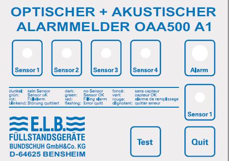
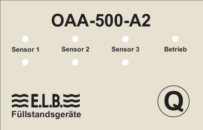
29 Z _englischeBeschr_Mai2016.doc Status: Page: 29/31 OAA-500- Optical and Acoustic Warning Device (Fig. 15, 16): Mains OAA- 500-A1 horn lamp collective interference channel 1 sensors channel 2 channel 3 channel 4 Fig.: 15 Terminal assignment OAA-500-A1 The mains connection PE 41, 51 = L ( + ) 42, 52 = N ( - ) Output relay lamp 31 = COM 32 = NO 33 = NC Output relay horn 21 = COM 22 = NO 23 = NC Sensor 1 2 = + 12 VDC 3 = Input (12 VDC) 4 = GND ( - ) Sensor 2 12 = + 12 VDC 13 = Input (12 VDC) 14 = GND ( - ) Sensor 3 5 = + 12 VDC 6 = Input (12 VDC) 7 = GND ( - ) Sensor 4 15 = + 12 VDC 16 = Input (12 VDC) 17 = GND ( - ) Input ext. acknowledgem. 1, 11 pot.-free NO-contact Mains sensors OAA-500-A2 horn lamp collective interference channel 1 channel 2 channel 3 channel 4 Fig.: 16
30 Z _englischeBeschr_Mai2016.doc Status: Page: 30/31 Terminal assignment OAA-500-A2 The mains connection 2 = L ( + ) 1 = N ( - ) Output relay lamp 7 = COM 9 = NO 8 = NC Output relay horn 10 = COM 12 = NO 11 = NC Sensor 1 13 = + 12 VDC 14 = Input (12 VDC) 15 = GND ( - ) Sensor 2 16 = + 12 VDC 17 = Input (12 VDC) 18 = GND ( - ) Sensor 3 19 = + 12 VDC 20 = Input (12 VDC) 21 = GND ( - ) Input ext. acknowledgem. 22, 23 pot.-free NO-contact 6. Setting Instructions The leak detector (Fig ) must be inserted with due consideration to the conditions specified in the respective country s ordinances on installations for handling water-polluting substances. Thanks to their design, the leak detectors guarantee that a signal indicating a leakage fluid will be given once a response height of max. 5 mm is reached. It is therefore not necessary to set the response height. Sensitivity of the measuring transducer: After connecting the electrodes and the supply voltage, the electrode relay can be set to suit the media to be monitored once the electrode sensors have been immersed into the fluid requiring monitoring. For this purpose the response sensitivity must be set to the lowest level (turn the potentiometer in an anti-clockwise direction as far as it will go). L: Cable length 140 Introduction of the probe (accessories, possibly a cable attached by a customer) Cable Tank Drip tray Cable sealing Probe body Sensor electrodes Now turn the potentiometer in a clockwise direction until the output relay drops out (ER-107: "Alarm", lights up in red; ER- A , ER-145/A/EX: "Condensate" green goes out and ER-117/-217 OUT lights up in yellow). Once this position is reached, turn the potentiometer another further (by 1 revolution in the ER-117/-217) to allow for fluctuations in conductivity. Abb.: 17
31 Z _englischeBeschr_Mai2016.doc Status: Page: 31/31 Connection cable Drip tray Tank Sensor electrode Optional fastening (M6) Body Abb.: 18 A 7. Operating Instructions The leak prevention device, consisting of the conductive electrode and the electrode relay, does not require maintenance if it is used in accordance with its intended purpose. Warning devices must be placed downstream of the system parts of the leak prevention device in accordance with this description. The separated change-over contacts of the output relay can be used at the same time for this purpose. The general operating instructions for the downstream devices must be observed here. 8. Periodic Inspections The leak prevention devices must be tested for correct functioning by the owner/managing operator at regular intervals, at least once a year. The test for correct functioning must be performed in a way that will verify the perfect functioning of the leak prevention device in interaction with all components. The leak detector must be lowered along the lead into the appropriate storage tank. Alternatively, the test can also be conducted in a suitable test vessel with storage fluid. Once the electrode sensor is immersed into the storage fluid, the leakage message must appear. Care must be taken that only the leak detector and not the lead is immersed into the fluid. Testing the fault: the signal line is interrupted and then short-circuited. In both cases the fault message and the leakage message must appear. If the ability of the leak prevention device and the measuring transducer to function properly is recognisable in another way (exclusion of function-inhibiting faults), the test can also be done by simulating the corresponding output signal. Further instructions for the testing methodology can be found in e.g. Directive VDI/VDE 2180, page 4.
Level and Pressure. Product Information. Conductive level detection
 Level and Pressure Product Information Conductive level detection Contents Contents 1 Product description 1.1 Application... 1. Function... 5 1. Types/Versions... 6 1.4 Application examples... 8 1.5 Adjustment...
EC centrifugal fan - RadiCal
 R3G3-RO36-8 ebm-papst Mulfingen GmbH & Co. KG Bachmühle D-74673 Mulfingen Phone +49 7938 8- Fax +49 7938 8- info@de.ebmpapst.com www.ebmpapst.com Limited partnership Headquarters Mulfingen County court
Operating Instructions
 Level and Pressure Operating Instructions VEGATOR 620, 621, 622 max. 0 10 min. 0 10 on VEGATOR 622! 6 7 8 9 10 11 12 13 14 in out Contents Contents Safety information... 2 Note Ex area... 2 1 Product description
Installation and Operating Instructions Differential pressure transmitter for potentially explosive areas. MG-1000-EEx USAGE STRUCTURE AND DESIGN
 Installation and Operating Instructions Differential pressure transmitter for potentially explosive areas Mimablad: 176GB/1999-10-25 Ersätter: MG-1000-EEx USAGE MG-1000-EEx is suitable for use in measurement
10/2 Product overview. 10/3 4AC3 0, 4AC3 1 bell transformers. 10/5 4AC AC3 6 transformers for permanent loads. 10/8 4AC2 4 power supply units
 BETA Switching Transformers, Bells and Socket Outlets /2 Product overview /3 4AC3 0, 4AC3 1 bell transformers /5 4AC3 4... 4AC3 transformers for permanent loads /8 4AC2 4 power supply units / 7LQ2 2 bells
XR1 Rotor Earth Fault Relay. (May 2007) Manual XR1 (Revision New)
 Manual XR1 (Revision New)") XR1 Rotor Earth Fault Relay (May 2007) Manual XR1 (Revision New) Woodward Manual XR1 GB Woodward Governor Company reserves the right to update any portion of this publication at any time. Information provided
XR1 Rotor Earth Fault Relay (May 2007) Manual XR1 (Revision New) Woodward Manual XR1 GB Woodward Governor Company reserves the right to update any portion of this publication at any time. Information provided
Digital inductive conductivity transmitter
 Digital inductive conductivity transmitter Optimal solution for conductivity measurements in difficult fluids (polluted, dirty,...) PEEK/PPA version for CIP applications Large range of process connections
The transducer component converts the measured signal and displays the actual value.
 Digital inductive conductivity transmitter System Integration Provides low Total Cost of Ownership PEEK/PPA version for CIP applications TEACH IN and SIMULATION Function Approval PVDF Version PEEK Version
XR1 Rotor Earth Fault Relay. Manual XR1 (Revision C)
") XR1 Rotor Earth Fault Relay Manual XR1 (Revision C) Woodward Manual XR1 (EN) Woodward Governor Company reserves the right to update any portion of this publication at any time. Information provided by
XR1 Rotor Earth Fault Relay Manual XR1 (Revision C) Woodward Manual XR1 (EN) Woodward Governor Company reserves the right to update any portion of this publication at any time. Information provided by
EC centrifugal fan. backward curved, single inlet
 RG6-AB6- ebm-papst Mulfingen GmbH & Co. KG Bachmühle 6 Mulfingen Phone: + 798 8- Fax: + 798 8- www.ebmpapst.com info@de.ebmpapst.com Nominal data Type Motor RG6-AB6- MG-IF Phase ~ Nominal voltage [VAC]
Electronic relays. Monitoring. Monitoring
 Electronic relays Neither overload nor underload are particularly good for machines and installations in industrial applications. An unsteady power supply may lead to machine failure and, thus, expensive
Pulse Scaler for DIN Rail Attachment
 Type 651 Pulse Scaler for DIN Rail Attachment Programmable pulse scaling factor up to 2047:1 NAMUR generator input PNP transistor output Max. pulse frequency 5 khz PROGRAMMING The divisor is set in binary
2.7. IT system floor-standing distribution cabinet Series -IPS-F/EDS
 Dipl.-Ing. W. Bender GmbH & Co. KG Londorfer Str. 65 35305 Grünberg Tel.: 0640 807-0 Fax: 0640 807-259 IT system floor-standing distribution cabinet Series -IPS-F/EDS for supplying power to medical locations
Level detection in liquid. Conductive. VEGAKON 61 VEGAKON 66 Probes EL 1, 3, 4, 6, 8. Product Information
 Level detection in liquid Conductive VEGAKON 6 VEGAKON 66 Probes EL,, 4, 6, 8 Product Information Content Content Description of the measuring principle...........................................................
Glass-fibre-reinforced polycarbonate. Dead zone Adaptive or fixed from % 1.5 s adjustable. 20 ms. 60 ms. 60 ms. Approx. 1.
 General data Mounting On linear actuators On quarter turn actuators ARCA-integrated or to VDI/VDE 3847-1 or IEC 534-6 (NAMUR) Range of stroke: 3... 130 mm Integrated to VDI/VDE 3847-2 or VDI/VDE 3845 Angle
ADC5000 SERIES. AC/DC Switch Mode Power Supplies and Rectifiers for Industrial and Telecom Applications. 60W, 125W and 250 W
 ADC5000 SERIES AC/DC Switch Mode Power Supplies and Rectifiers for Industrial and Telecom Applications 60W, 125W and 250 W Input voltage 230/115 VAC voltages 12, 24, 36 or 48 VDC Statistical MTBF >3 000
Type PLC Fitting. Valve for Continuous control. Diaphragm valve. Output
 Digital Inductive conductivity transmitter Optimal solution for conductivity measurements in difficult fluids (polluted, dirty,...) PEEK/PPA version for CIP applications Large range of process connections
Ult r a s o n i c le v e l me t e r s ULM 55
 Ult r a s o n i c le v e l me t e r s ULM 55 For continuous level measurement of liquids (even if polluted), mash and paste materials in open or closed vessels, sumps, open channels etc. Xi version for
Capacitive levels controllers
 Capacitive levels controllers for automatic control, regulation and signalling of levels of conductive and non-conductive liquids or pourable bulk goods Jola Spezialschalter GmbH & Co. KG Klostergartenstr.
PHOENIX CONTACT - 09/2009
 Electronic miniature circuit-breaker CLIPLINE Data sheet 03906_en_0 PHOENIX CONTACT - 09/2009 Description The EC-E... electronic miniature circuit-breaker selectively protects all 24 V DC load circuits
Process displays For standard signals, temperature, resistance measurement
 Features Inputs: Voltage ±10 V, ±200 V / Current ±20 ma / thermocouples J,K,T,N,Pt100,Pt1000 / resistance measurement / potentiometer Display range can be linearised Two limits output Min, Max functions
Electronic Circuit Breaker ESS1 for System SVS1
 Electronic Circuit Breaker for System SVS Description The electronic circuit breaker is designed to ensure selective disconnection of individual s in industrial systems which are powered by a DC 24 V switch
Catalogue 1SFC en, Edition 3 November 2003 Supersedes Catalogue 1SFC en, Edition 2 November Arc Guard System TVOC
 Catalogue 1SFC 266006-en, Edition 3 November 2003 Supersedes Catalogue 1SFC 266006-en, Edition 2 November 2000 Arc Guard System TVOC System units The two units of the are used as below: Approvals 1. with
Valve Island with Electronic I/O
 Screw in Temperature /Switch with display for ON/OFF Control Indication, monitoring, transmission and ON/OFF control in one device Extra large display Menu guided parametrisation Complete communication
ph or ORP Transmitter
 ph or ORP Transmitter Programmable outputs: two transistor and single or dual analog 4-20 ma (Process + Temp) Removable backlighted display Universal process connection Compatible with 120 mm ph/ ORP probes
Digital flow transmitter for continuous flow measurement
 Digital flow transmitter for continuous flow measurement Compact or remote version for DN 06 to 400, PN10 Shows both flow rate and volume (with two totalizers) Automatic-calibration: TEACH-IN Simulation:
Glass-fibre-reinforced polycarbonate. Dead zone Adaptive or fixed from % 20 ms. 60 ms. 60 ms. Approx. 1.3 kg. Approx. 0.9 kg. Approx. 5.
 General data Mounting On linear actuators On quarter turn actuators ARCA-integrated or to VDI/VDE 3847-1 or IEC 534-6 (NAMUR) Range of stroke: 3... 130 mm Integrated to VDI/VDE 3847-2 or VDI/VDE 3845 Angle
Measuring and Controlling Unit Multronic OC
 Measuring and Controlling Unit Multronic OC One channel measuring and controlling unit for ph / conductivity / Chlorine measuring Automatic temperature compensation Measuring and control behaviour simultaneously
EC centrifugal fan. backward curved, single inlet
 RG56-AG7- ebm-papst Mulfingen GmbH & Co. KG Bachmühle 746 Mulfingen Phone: +49 798 - Fax: +49 798 - www.ebmpapst.com info@de.ebmpapst.com Nominal data Type Motor RG56-AG7- MG-FF Phase ~ Nominal voltage
Digital conductivity transmitter
 Digital conductivity transmitter Compact version with integrated conductivity electrodes Remote version with seperated transmitter for short (15 ft.) or long (1500 ft.) distance Commissioning is easy due
400 (±2,5 V/ V/ ,3% V4A
 LVDT Inductive Position Transducer - Hydraulic Series Series Hydraulic position measurement in hydraulic cylinders of machine controls ranges 10...300 mm temperature -40...+150 C (sensors) 0...+60 C (external
Electronic Circuit Breaker ESS1 for System SVS1
 Electronic Circuit Breaker for System SVS Description The electronic circuit breaker is designed to ensure selective disconnection of individual s in industrial systems which are powered by a DC 24 V switch
1000TR. Instructions
 1000TR ph Instructions CONTENTS 1. INTRODUCTION... 2 1.1 COMMON INTRODUCTION... 2 1.2 PARTS & ACCESSORIES... 2 2. INSTALLATION... 3 2.1 CASING... 3 2.2 MOUNTING... 3 2.3 ELECTRICAL INSTALLATION... 3 2.3.1
Assembly. Front view. DIP switch. LED yellow: Relay output 1. LED yellow: Relay output Power Rail
 Current/Voltage Trip Value Features Assembly 1-channel signal conditioner 24 V DC supply (Power Rail) Current and voltage input 2 relay outputs Programmable high/low alarm Configurable via DIP switches
DEIF A/S. Insulation monitor. Type SIM-Q
 Insulation monitor 4921232C Monitoring of insulation resistance on ungrounded AC networks (IT network) Working voltage up to 69V AC, withstands up to V DC Measuring range 1...Mohm or 1...Mohm Alarm on
Liquid level monitors and controls
 Liquid level monitors and controls ontent M-ENE, M-ENE MAX... / 8 M-ENS... / 83 M-ENS UP/DOWN... / 84 M-ENN... / 85 M-ENN UP/DOWN... / 86 Accessories for liquid level relays... / 87 Technical data M-ENE,
Analogue temperature controllers
 Analogue temperature controllers CT8A Input by J-K thermo-couple or by thermo-resistance Pt 00 (-wire) regulation modes : ON/OFF or proportional derivative selected by wiring Relay output Specifications
Electromagnetic Flow Transmitter
 Electromagnetic Flow Transmitter Sensor in solid state technology Working as a transmitter and/or as an On/Off controller Automatic-calibration of full scale: Teach-In Clean in place (CIP) Type can be
Operating Instruction
 Level and Pressure Operating Instruction VEGASEL 643 6 5 + + 3 5 + + max. min. on VEGASEL 643 5 6 7 8 9 10 11 12 13 14 in out Contents Contents Safety information... 2 1 Product description 1.1 Function
Resistance thermometers for process technology
 Data Sheet 90.2820 Page 1/8 Resistance thermometers for process technology for temperatures from -200 to +600 C with protection tubes in stainless steel, titanium, tantalum, Iconel and Hastelloy available
Assembly. Front view. DIP switch. LED yellow: Relay output I. LED yellow: Relay output II. Potentiometer Hysteresis relay I Power Rail
 Current/Voltage Trip Value Features Assembly 1-channel signal conditioner 24 V DC supply (Power Rail) Current and voltage input 2 relay outputs Programmable high/low alarm Configurable via DIP switches
INSERTION paddle wheel flowmeter for continuous flow measurement
 INSERTION paddle wheel flowmeter for continuous flow measurement Economic integration in pipe systems without any additional piping 3-wire frequency pulse version to directly interface with PLC s (both
Float Switches with Permanent Magnet For Vertical Installation Model RSM
 Level Measurement Float Switches with Permanent Magnet For Vertical Installation Model RSM WIKA Data Sheet LM 30.01 Applications Level measurement for almost all liquid media Pump/level control and monitoring
Theta 60R. Technical Data Sheet. Special Features. Fig. 2 Theta R, 2 channel version, in housing S17 hole mounting brackets pulled out.
 Technical Data Sheet Theta 60R 60 R 60 R Fig. Theta R, channel version, in housing S7 clipped on to a top - hat rail. Fig. Theta R, channel version, in housing S7 hole mounting brackets pulled out. Theta
P R o D u c T I n F o R m at I o n. TDR Level Sensor LFP. The clean solution
 P R o D u c T I n F o R m at I o n TDR Level Sensor The clean solution Level sensors The clean solution Product description The is a hygienic level sensor for liquids using TDR technology a process for
Digital batch controller
 INSERTION Digital batch controller Type 8025 can be combined with... Compact or remote version for DN06 to DN400, PN10 Dosing On site calibration by Teach-In Check of input/output signals Total and daily
Electromagnetic flowmeters and switches DWM 1000/2000
 KROHNE 10/2000 D 20 DW10 02 E GR Electromagnetic flowmeters and switches DWM 1000/2000 Variable area flowmeters Vortex flowmeters Flow controllers Electromagnetic flowmeters Ultrasonic flowmeters Mass
SET Installation and Operating Instructions. Level switch for two sensors
 Labkotec Oy Myllyhaantie 6 FI-33960 PIRKKALA FINLAND Tel: + 358 29 006 260 Fax: + 358 29 006 1260 20.2.2013 Internet: www.labkotec.fi 1/14 SET-2000 Level switch for two sensors Copyright 2013 Labkotec
Technical Information Nivector FTC968, FTC968Z
 TI0007F/00/EN/7.6 7494 Products Solutions Services Technical Information Nivector FTC968, FTC968Z Capacitance Point level switch for powder and fine-grained bulk solids Application The Nivector is a small-sized
MODEL AT-10 ANALOG TRANSMITTER
 MODEL AT-10 ANALOG TRANSMITTER INSTALLATION & OPERATING MANUAL Industrial Weighing Systems 9 Richmond Street Picton, Ontario K0K 2T0 Phone: 613-921-0397 Fax: 613-476-5293 Web: www.iwsystems.ca info@iwsystems.ca
XT Technical Documentation. The magnetostrictive level sensor. Edition: Version: 1 Article no.:
 Technical Documentation The magnetostrictive level sensor Edition: 11-2010 Version: 1 Article no.: 233571 Gems Sensors & Controls One Cowles Rd Plainville CT Telephone 800-378-1600 Page 2/19 Table of contents
ISOMETER IRDH575. Approvals
 Insulation monitoring device for unearthed AC, DC and AC/DC systems (IT systems) with control and display function for EDS insulation fault location systems IRDH575_D00089_02_D_XXEN/09.2018 Insulation
Level and Pressure. Product Information. Vibrating level switches
 Level and Pressure Product Information Vibrating level switches Contents Contents 1 Product description 1.1 VEGAVIB... 3 1.2 VEGASWING... 3 2 Function and application 2.1 Functional principle... 5 2.2
KFS. Flap-type flow meter. Design and range of application
 Design and range of application The measuring device operates largely independent of viscosity and is suitable for indicating the flow rate of water, acids, alkaline solutions and gases. Every device is
Documentation. Content. Measurement and Control. Type: ELT-GP1. 1. Installation instructions 2. Data sheets 3. Declarations of conformity
 Documentation Measurement and Control Type: ELT-GP1 Content 1. Installation instructions 2. Data sheets 3. Declarations of conformity (Part No. 008Q520) eltherm GmbH Ernst-Heinkel-Str. 6-10 57299 Burbach
Digital flowmeter for continuous flow measurement
 8025 Flowmeter INSERTION Digital flowmeter for continuous flow measurement Compact or remote version for DN06 to DN400, PN10 Displays both flow rate and volume (with two totalizers) On site calibration
Sitron Capacitive Level Sensors
 Sitron Capacitive evel Sensors Models: SC404 SC120CN200 SC400V400 SC700 Introduction Capacitive evel Sensors, also referred to as Radio Frequency (RF) level sensors, are used for measuring process level
B850 Boiler House Energy Monitor
 Local regulations may restrict the use of this product to below the conditions quoted. In the interests of development and improvement of the product, we reserve the right to change the specification without
Temperature Input Module for Zone 1 Series 9482/32
 www.stahl.de > 8 channels for temperature sensors > Intrinsically safe inputs Ex ia > For Pt-, Ni- and Cu-resistance temperature detectors according to DIN, IEC and GOST in 2-, 3- and 4-wire circuits >
Digital Input Output Module 24 V for Ex n Zone 2 Series 9472/35
 www.stahl.de > 16 channels can be adjusted in pairs as digital inputs or outputs > Suitable for NAMUR proximity switches, 3-wire PNP proximity switches, contacts and solenoid valves (24 V / 0.5 A). > Up
Electro Controls. Input-Output Modules WattsIndustries.co.uk
 Electro Controls Input-Output Modules - 2017 WattsIndustries.co.uk Input-Output Modules Section 08 B.M.S INPUT - OUTPUT MODULES SINGLE AND ADJUSTABLE RELAY ESRM.. Volt free contacts DIN RAIL mounted relay
LVDT. Inductive Position Transducer - Hydraulic Series. SM-HYD Hydraulic Series. Key-Features:
 LVDT Inductive Position Transducer - Hydraulic Series SM-HYD Hydraulic Series Key-Features: Content: - Screw flange M18x1,5 / M30x1,5 or plug-in flange Ø18 - Pressure up to 400 bar - Measurement range
JUMO CTI-500. Inductive Conductivity/Concentration and Temperature Transmitter with switch contacts. Type Brief description.
 Page 1/17 JUMO CTI-500 Inductive Conductivity/Concentration and Temperature Transmitter with switch contacts Type 202755 Brief description The instrument is used for the measurement/control of conductivity
Servomotor for butterfly valves VF, VFH. delta-elektrogas.com EE157-01/16
 MZ Servomotor for butterfly valves VF, VFH delta-elektrogas.com EE157-01/16 MZ Servomotor Contents Description.... 2 Features........ 2 Functioning and application..... 3 Technical specifications......
Electronic Circuit Protector ESX10-T
 Electronic Circuit Protector ESX0-T Description Electronic circuit protector type ESX0-T is designed to ensure selective disconnection of systems. power supplies, which are widely used in industry today,
Magnetic-inductive flow meter. PITe / UMF2. Technical Datasheet. Maintenance-free Nearly no pressure drop Robust design Easy installation and start-up
 Magnetic-inductive flow meter Technical Datasheet PITe / UMF2 Maintenance-free Nearly no pressure drop Robust design Easy installation and start-up Subject to change without notice 1 Function An electrically
Operating instructions Electronic level sensor LK / / 2008
 Operating instructions Electronic level sensor LK31 UK 704046 / 00 01 / 2008 Contents Safety instructions...2 Menu structure...3 Controls and indicating elements...4 Function and features...5 Functional
Electronic plugs for valves MSE
 Murrelektronik valve plugs with integrated electronic circuits. Saves time, money and space. Electronics With the Murrelektronik electronic valve plugs, we have made it possible to integrate many different
Overtravel of 3.5 mm max. Power source DC D5C-1DS0 D5C-1DP0 D5C-1DA0 AC D5C-1AS0 D5C-1AP0 D5C-1AA0 Antenna only D5C-00S0 D5C-00P0 D5C-00A0
 Touch Switch Unique 18 mm Capacitive Touch Switch with Choice of Three Actuators is Activated with Only a Very Slight Physical Contact Lightweight objects, such as thin wire or foil can be accurately detected.
Roline L1 Series. Humidity - Temperature Transmitters INSTRUCTION MANUAL
 Roline L1 Series Humidity - Temperature Transmitters INSTRUCTION MANUAL 20030314 CONTENTS Overview... 3 Operation... 5 Power supply... 5 Operating range and limits... 5 Temperature compensation of the
isolr275 / AGH-LR Digital Ground Fault Monitor / Ground Detector For Low-Resistance Ungrounded (Floating) AC/DC Systems
 AC/DC Systems") T M 1 isolr275 / AGH-LR Digital Ground Fault Monitor / Ground Detector For Low-Resistance Ungrounded (Floating) AC/DC Systems Technical Bulletin NAE1012110 / 12.2011 isolr275 / AGH-LR Ground Fault Monitor
T M 1 isolr275 / AGH-LR Digital Ground Fault Monitor / Ground Detector For Low-Resistance Ungrounded (Floating) AC/DC Systems Technical Bulletin NAE1012110 / 12.2011 isolr275 / AGH-LR Ground Fault Monitor
Magnetic Inductive Flow Sensor induq
 Operating manual (Translation) Operating manual... page 1-16 Magnetic Inductive Flow Sensor induq Series VMZ SIKA Ba_VMZ_en 10/2014. Please keep this operating manual for future reference. If the device
Operating Manual * * Differential pressure transmitter. Table of Contents. 1 Safety guidelines. 1.1 General Information
 *09005137* BA_EN_DE50 Rev.A 11/12 *09005137* d e v e l o p i n g s o l u t i o n s DE50 Operating Manual Differential pressure transmitter Table of Contents 1 Safety guidelines 2 Application purpose 3
OPTIFLUX 5000 Technical Datasheet
 OPTIFLUX 5000 Technical Datasheet Electromagnetic flowmeter in flanged version Exceptional long-term stability and accuracy For highly aggressive and abrasive fluids Fully vacuum-resistant with high-tech
Description of equipment
 Applicant: Electrical Apparatus: KROHNE Messtechnik GmbH & Co. KG Level Radar BM 70M-Ex Description of equipment The Types BM 70M-Ex Level Radar gauges serve to continuously measure the product level in
Local control stations for Zone 1 and Zone 21. Features. Description
 Local control stations for Zone and Zone Local control stations for Zone and Zone Features The right size/material enclosure Optimum functionality thanks to the great variety of components Customised planning
Digital flowmeter for continuous flow measurement
 8025 Flowmeter INSERTION Digital flowmeter for continuous flow measurement Compact or remote version for DN06 to DN400, PN10 Displays both flow rate and volume (with two totalizers) On site calibration
TS-9100 Electronic Sensors and Transducers. Features and Benefits. G Wide range of enclosures and signal outputs
 European Electronic Controls Catalogue Catalogue Section A Product Bulletin TS-9100 Issue Date 09 2000 TS-9100 Electronic Sensors and Transducers I ntroduction The TS-9100 series of electronic temperature
JUMO Dtrans T100 Screw-in RTD Temperature Probe with/without Transmitter
 ata Sheet 902815 Page 1/13 JUMO trans T100 Screw-in RT Temperature Probe with/without Transmitter For temperatures between -50 and +260 C RoHS conformity for EU and China Configuration with setup program
OEM miniature resistance thermometer Models TR31-3 and TR31-K, thread-mounted
 Electrical temperature measurement OEM miniature resistance thermometer Models TR31-3 and TR31-K, thread-mounted WIKA data sheet TE 60.31 further approvals see page 10 Applications Machine building, plant
Model Number Structure. Ordering Information. Solid-state Power OFF-delay Timer H3DE-H. Model Number Legend. List of Models
 Solid-state Power OFF-delay Timer H3DE-H Timers Two delay-time models available. 0.1 to 12 seconds (S Series) 1 to 120 seconds (L Series) Covers wide range of supply voltage. Model Number Structure Model
Capacitance Level Switch
 Capacitance Level Switch PRODUCT INTRODUCTION 4 PRINCIPLE The capacitance level switch measuring principle is based on the "capacitance effects". When this level switch is set on a silo, it will form a
LVDT. Inductive Position Transducer. SL Series. Key-Features:
 LVDT Inductive Position Transducer SL Series Key-Features: Content: - Measurement ranges 10...600 mm - External, or cable electronics with cable break detection - Linearity up to ±0.10 % of full scale
INLINE flowmeter for continuous flow measurement
 INLINE flowmeter for continuous flow measurement Economic integration in pipe systems without any additional piping 3-wire frequency pulse version to directly interface with PLC s (both PNP and NPN) Connection
Overview of types. Technical data
 echnical data sheet SHA-.. Multifunctional linear actuators for adjusting air dampers and slide valves in ventilation and air-conditioning systems for building services installations For air control dampers
LVDT. Inductive Position Transducer. SL Series. Key-Features:
 HM-1803 LVDT Inductive Position Transducer SL Series Key-Features: Content: - Measurement ranges 10...600 mm - External, or cable electronics with cable break detection - Linearity up to ±0.10 % of full
1-Phase True RMS AC/DC Over and Under Current Types DIC01, PIC01
 Monitoring Relays -Phase True RMS AC/DC Over and Under Current Types DIC0, PIC0 DIC0 PIC0 TRMS AC/DC over + under, over+over, under+under current and voltage monitoring relays DC process signal plus/minus
Level Measurement silometer FMX 570
 Technical Information TI 01F/00/en Level Measurement silometer FMX 570 Measurement of liquids and bulk solids Suitable for explosion hazardous areas For use with capacitance and hydrostatic probes The
INLINE flowmeter for continuous flow measurement
 INLINE flowmeter for continuous flow measurement Economic integration in pipe systems without any additional piping 3-wire frequency pulse version to directly interface with PLC s (both PNP and NPN) Connection
KFS-EM. Overall length. Al. PTFE coated Alu, painted Al. coated Methacrylate / acrylic nitrite
 KFS Flap Flow Meter KFS suitable for H, acids, alkalis and gases spring-loaded horizontal or vertical flow direction low pressure loss mainly viscosity independent optional threshold value contacts optional
Installation / Monitoring Technique
 Installation / Monitoring Technique VARIMETER RCM Residual Current Monitor, Type B for AC and DC Systems IP 5883 0249633 IP 5883 ND 5018/035 ND 5018/030 According to IEC/EN 62 020, VDE 0663 For AC and
Electronic Circuit Breaker ESS20-0..
 Description Electronic circuit breaker type ES-0.. is designed to ensure selective disconnection of individual loads in systems which are powered by a DC 4 V switch-mode power supply. DC 4 V power supplies,
Type EXT with cable, probe sold
 standard signal FF-GLT-Series Description Type INT for duct mounting, probe installed Type EXT with cable, probe sold Type AF for wall mounting, probe sold Characteristic features Standard signal 0...
Operating Instructions
 Operating Instructions FLUDEX-EOC system A. Friedr. Flender AG 46393 Bocholt Tel. 02871/92-0 Telefax 02871/92-2596 www.flender.com Contents 1. Application 3 2. Operation 3 3. Fitting 4 3.1 Fitting transmitter
INSTALLATION AND OPERATION MANUAL
 Version 2.2 MS1016 MTF SERIES VIBRATING PROBES FOR LIQUIDS AND HYC-PKK-312 SWITCHING ISOLATOR INSTALLATION AND OPERATION MANUAL Hycontrol Limited, Larchwood House, Orchard Street, Redditch, Worcestershire,
Isolators A3/1.
 Temperature Transmitter Series 9182 > One unit for nearly all temperature sensors indivdually configurable > Signal duplication possible > Galvanic isolation between input, output, power supply and configuration
Smart Power Relay E I...
 Smart Power Relay E-48-8I... Description The Smart Power Relay E-48-8I.- is a remotely controllable electronic load disconnecting relay with three functions in a single unit: l electronic relay l electronic
Endress Hauser. SmarTec M CLD 133 Conductivity Measurement
 Technical Information / Operating Instructions TI 281C/07/en/08.02 No. 51506567 SmarTec M Conductivity Measurement Compact conductivity transmitter with inductive sensor and integrated temperature compensation
INSTRUCTION MANUAL (ATEX / IECEx)
") INSTRUCTION MANUAL (ATEX / IECEx) STExS1 & STExS2 Sounder For use in Flammable Gas and Dust Atmospheres 1) Warnings DO NOT OPEN WHEN AN EXPLOSIVE ATMOSPHERE IS PRESENT POTENTIAL ELECTROSTATIC CHARGING
INSTRUCTION MANUAL (ATEX / IECEx) STExS1 & STExS2 Sounder For use in Flammable Gas and Dust Atmospheres 1) Warnings DO NOT OPEN WHEN AN EXPLOSIVE ATMOSPHERE IS PRESENT POTENTIAL ELECTROSTATIC CHARGING
LVDT. Inductive Position Transducer - Hydraulic Series. SM-HYD-F18 Hydraulic-Series. Key-Features:
 LVDT Inductive Position Transducer - Hydraulic Series SM-HYD-F18 Hydraulic-Series Key-Features: Content: - M18x1,5 mm integral thread - Operating pressure 150 bar - Ranges 2...200 mm - Linearity up to