S=E H ANTENNA RADIATION
|
|
|
- Herbert Lane
- 6 years ago
- Views:
Transcription
1 ANTENNA RADIATION Antennas radiate spherical waves that propagate in the radial direction for a coordinate system centered on the antenna. At large distances, spherical waves can be approx imated by plane waves. Plane waves are useful because they simplify the problem. They are not physical, however, because they require infinite power.the Poynting vector describes both the direction of propagation and the power density of the electromagnetic wave. It is found from the vector cross product of the electric and magnetic fields and is denoted S: S=E H W/m Fundamental Antenna Parameters Describe the antenna performance with respect to space distribution of the radiated energy, power efficiency, matching to the feed circuitry, etc. Many of these parameters are interrelated. Radiation pattern. Pattern beamwidths. Radiation intensity. Directivity. Gain. Antenna efficiency and radiation efficiency. Frequency bandwidth. Input impedance and radiation resistance. Antenna effective area. Relationship between directivity and antenna effective area 1
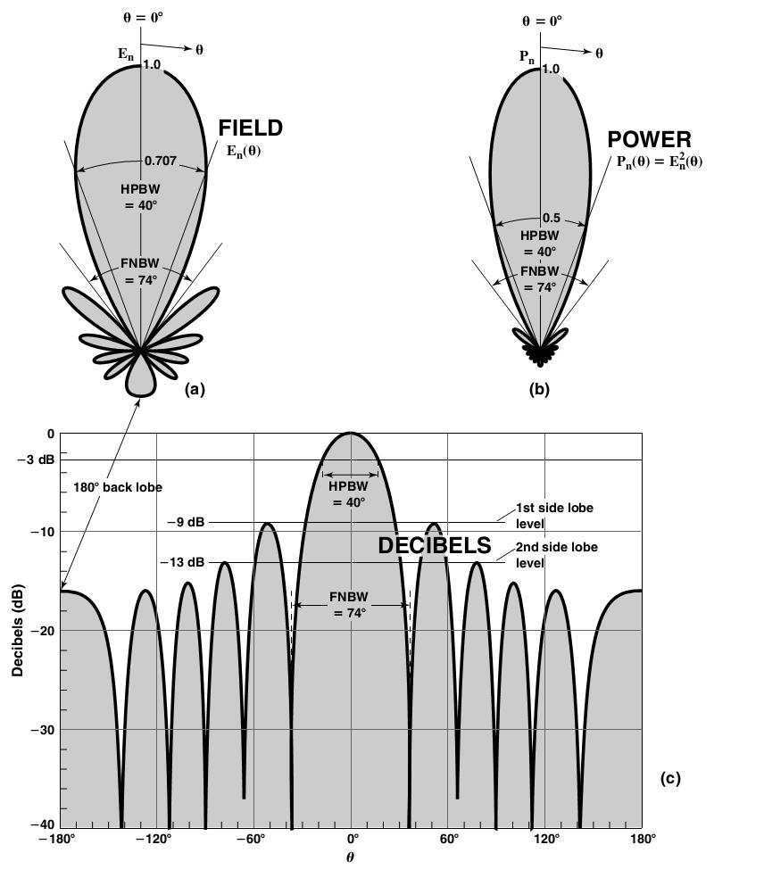
2 Radiation pattern The radiation pattern of antenna is a representation (pictorial or mathematical) of the distribution of the power radiated from the antenna as a function of direction angles from the antenna. Antenna radiation pattern (antenna pattern) is defined for large distances from the antenna, where the spatial (angular) distribution of the radiated power does not depend on the distance from the radiation source (in the far field). Normalized pattern: Often the field and power patterns are normalized with respect to their maximum value, yielding normalized field and power patterns. Also, the power pattern is usually plotted on a logarithmic scale or more commonly in decibels (db). This scale is usually desirable because a logarithmic scale can accentuate in more details those parts of the pattern that have very low values, which later we will refer to as minor lobes. For an antenna, the a) field pattern(in linear scale) typically represents a plot of the magnitude of the electric or magnetic field as a function of the angular space. b) power pattern(in linear scale) typically represents a plot of the square of the magnitude of the electric or magnetic field as a function of the angular space. c) power pattern(in db) represents the magnitude of the electric or magnetic field, in decibels, as a function of the angular space. When the patterns are plotted on a linear scale, the field pattern and power pattern may look very different. However, when the patterns are plotted on a logarithmic scale (db plot), both the normalized field and power patterns are the same since 10 log(p/pmax) is the same as 20 log(e/emax). Thus, in practice, we often plot the patterns in db scale, which also makes it easy to see details of the field or power over a large dynamic range, especially some minor side lobes. Radiation Pattern Lobes Various parts of a radiation pattern are referred to as lobes, which may be sub classified into major or main, minor, side, and back lobes 2
3 3

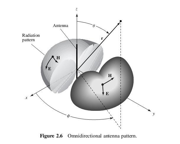
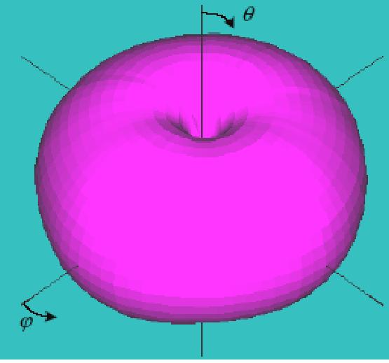
4 For an amplitude pattern of an antenna, there would be, in general, three electric-field components(er,eθ,eφ)at each observation point on the surface of a sphere of constant radius r =rc. In the far field, the radial Er component for all antennas is zero or vanishingly small compared to either one, or both, of the other two components.some antennas, depending on their geometry and also observation distance, may have only one, two, or all three components. In general, the magnitude of the total electric field would be E E E E r Isotropic, Directional, and Omnidirectional Patterns An isotropic radiator is defined as a hypothetical lossless antenna having equal radia-tion in all directions. Although it is ideal and not physically realizable, it is often taken as a reference for expressing the directive properties of actual antennas. A directional antenna is one having the property of radiating or receiving electromagnetic waves more effectively in some directions than in others. This term is usually applied to an antenna whose maximum directivity is significantly greater than that of a half-wave dipole. omnidirectional, and it is defined as one having an essentially non directional pattern in a given plane and a directional pattern in any orthogonal plane.an omnidirectional pattern is then a special type of a directional pattern. 4
5 5
.")
6 2.2.4 Field Regions Radian and Steradian The measure of a plane angle is a radian. One radian is defined as the plane angle with its vertex at the center of a circle of radius r that is subtended by an arc whose length is r. A graphical illustration is shown in Figure 2.10(a). Since the circumference of a circle of radius r is C=2πr, there are 2π rad (2πr/r) in a full circle. The measure of a solid angle is a steradian. One steradian is defined as the solid angle with its vertex at the center of a sphere of radius that is subtended by a spherical surface area equal to that of a square with each side of length r. A graphical illustration is shown in Figure 2.10(b). Since the area of a sphere of radius r is A=4πr 2,there are 4π sr (4πr 2 /r 2 ) in a closed sphere. 6
7 2.3 RADIATION POWER DENSITY The quantity used to describe the power associated with an electromagnetic wave is the instantaneous Poynting vector defined as 7
8 Since the Poynting vector is a power density, the total power crossing a closed surface can be obtained by integrating the normal component of the Poynting vector over the entire surface. In equation form For applications of time-varying fields, it is often more desirable to find the average power density which is obtained by integrating the instantaneous Poynting vector over one period and dividing by the period. If the real part of (E H )/2 represents the average (real) power density, what does the imaginary part of the same quantity represent? At this point it will be very natural to assume that the imaginary part must represent the reactive (stored) power density associated with the electromagnetic fields. In later chapters, it will be shown that the power density associated with the electromagnetic fields of an antenna in its far-field region is predominately real and will be referred to as radiation density. the average power radiated by an antenna (radiated power) can be written as 8
9 2.4 RADIATION INTENSITY Radiation intensity in a given direction is defined as the power radiated from an antenna per unit solid angle. The radiation intensity is a far-field parameter, and it can be obtained by simply multiplying the radiation density by the square of the distance. Since in a radiated wave is proportional to 1/R 2.It is convenient to define radiation intensity to remove the 1/R 2 dependence: In mathematical form it is expressed as where U=radiation intensity (W/unit solid angle) Wrad =radiation density (W/m2) Radiation intensity depends only on the direction of radiation and remains the same at all distances. A probe antenna measures the relative radiation intensity (pattern) by moving in a circle (constant R) around the antenna. For anisotropic source U will be independent of the angles θ and φ,as was the case for Wrad. 9
10 The radiation intensity is also related to the far-zone electric field of an antenna, Eθ,Eφ =far-zone electric-field components of the antenna η=intrinsic impedance of the medium The radial electric-field component(er)is assumed, if present, to be small in the far zone. The total power is obtained by integrating the radiation intensity, as given by over the entire solid angle of 4π. Thus Beamwidth, BW Half-power beamwidth (HPBW) also called the 3dB beam width or just the beam width(to identify how sharp the beam is) is the angle between two vectors from the pattern s origin to the points of the major lobe where the radiation intensity is half its maximum 11
11 First-null beamwidth (FNBW) is the angle between two vectors, originating at the pattern s origin and tangent to the main beam at its base. Often FNBW 2*HPBW 11
12 12
13 2.6 DIRECTIVITY Every real antenna radiates more energy in some directions than in others (i.e. has directional properties. Therefore directivity of an antenna defined as the ratio of the radiation intensity in a given direction from the antenna to the radiation intensity averaged over all directions. The average radiation intensity is equal to the total power radiated by the antenna divided by 4π. If the direction is not specified, it implies the direction of maximum radiation intensity (maximum directivity) expressed as D=directivity (dimensionless) D0 =maximum directivity (dimensionless) U=radiation intensity (W/unit solid angle) Umax=maximum radiation intensity (W/unit solid angle) U0 =radiation intensity of isotropic source (W/unit solid angle) Prad =total radiated power (W) The directivity of an isotropic source is unity since its power is radiated equally well in all directions. For all other sources, the maximum directivity will always be greater than unity, and it is a relative figure of merit which gives an indication of the directional properties of the antenna as compared with those of an isotropic source. The directivity can be smaller than unity; in fact it can be equal to zero. The values of directivity will be equal to or greater than zero and equal to or less than the maximum directivity (0 D D0) 13
14 14
15 15
16 16
17 2.6.1 Directional Patterns Instead of using the exact expression of (2-23) to compute the directivity, it is often convenient to derive simpler expressions, even if they are approximate, to compute the directivity. These can also be used for design purposes. For antennas with one narrow major lobe and very negligible minor lobes, the beam solid angle is approximately equal to the product of the half-power beamwidths in two perpendicular planes With this approximation, can be approximated by Kraus formula 17
18 The validity of the previous equation is based ona pattern that has only one major lobeand any minor lobes, if present, should be of very low intensity. Or by Tai & Pereira formula 2.8 ANTENNA EFFICIENCY Associated with an antenna are a number of efficiencies and can be defined using Figure The total antenna efficiency e0 is used to take into account losses at the input terminals and within the structure of the antenna. Such losses may be due, referring to Figure 2.22(b), to 1. reflections because of the mismatch between the transmission line and the antenna 2.I 2 R losses (conduction and dielectric) 18
19 In general, the overall efficiency can be written as 19
20 Usually ec and ed are very difficult to compute, but they can be determined experimentally. Even by measurements they cannot be separated, and it is usually more convenient to write as GAIN Another useful measure describing the performance of an antenna is the gain. Although the gain of the antenna is closely related to the directivity, it is a measure that takes into account the efficiency of the antenna as well as its directional capabilities. Remember that directivity is a measure that describes only the directional properties of the antenna and it is therefore controlled only by the pattern. Gain of an antenna (in a given direction) is defined as the ratio of the intensity, in a given direction, to the radiation intensity that would be obtained if the power accepted by the antenna were radiated isotropically. The radiation intensity corresponding to the isotropically radiated power is equal to the power accepted (input) by the antenna divided by 4π. gain does not include losses arising from impedance mismatches (reflection losses) and polarization mismatches (losses). 21
21 Thus, we can introduce an absolute gain Gabs that takes into account the reflection/mismatch losses (due to the connection of the antenna element to the transmission line), and it can be written as If lossless antenna, G=D If the antenna is matched to the transmission line, that is, the antenna input impedance Zin is equal to the characteristic impedance Zc of the line( =0), then the two gains are equal(gabs =G). 21
22 Usually the gain is given in terms of decibels instead of the dimensionless quantity The conversion formula is given by For many practical antennas an approximate formula for the gain, In practice, whenever the term gain is used, it usually refers to themaximum gain 2.11 BANDWIDTH The bandwidth of an antenna is defined as the range of frequencies within which the performance of the antenna, with respect to some characteristic, conforms to a specified standard. The bandwidth can be considered to be the range of frequencies, on either side of a center frequency (usually the resonance frequency for a dipole), where the antenna characteristics (such as input impedance, pattern, beamwidth, polarization, side lobe level, gain, beam direction, radiation efficiency) are within an acceptable value of those at the center frequency. Because the characteristics (input impedance, pattern, gain, polarization, etc.) of an antenna do not necessarily vary in the same manner or are even critically affected by the frequency, there is no unique characterization of the bandwidth. The specifications are set in each case to meet the needs of the particular application. Usually there is a distinction made between pattern and input impedance variations. Accordingly pattern bandwidth and impedance bandwidth are used to emphasize this distinction. Associated with pattern bandwidth are gain, side lobe level, beamwidth, polarization, and beam direction while input impedance and radiation efficiency are related to impedance bandwidth. 22

23 2.12 POLARIZATION Polarization of an antenna in a given direction is defined as the polarization of the wave transmitted (radiated) by the antenna. At any point in the far field of an antenna the radiated wave can be represented by a plane wave whose electric-field strength is the same as that of the wave and whose direction of propagation is in the radial direction from the antenna. As the radial distance approaches infinity, the radius of curvature of the radiated wave s phase front also approaches infinity and thus in any specified direction the wave appears locally as a plane wave. Polarization may be classified as linear, circular, or elliptical. If the vector that describes the electric field at a point in space as a function of time is always directed along a line, the field is said to be linearly polarized. 23
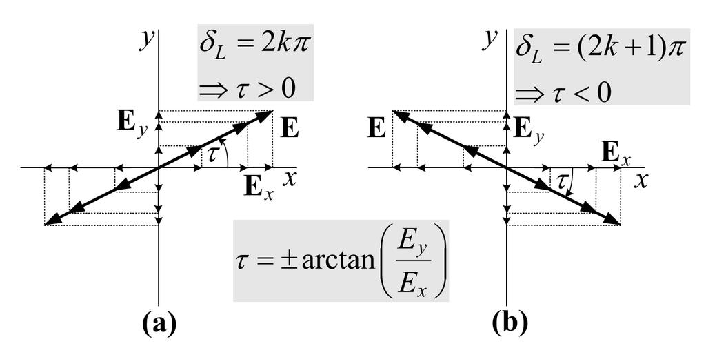
24 In general, however, the figure that the electric field traces is an ellipse, and the field is said to be elliptically polarized. Linear and circular polarizations are special cases of elliptical, and they can be obtained when the ellipse becomes a straight line or a circle, respectively. The figure of the electric field is traced in a clockwise(cw) or counterclockwise(ccw) sense. Clockwise rotation of the electric-field vector is also designated as right-hand polarization and counterclockwise as left-hand polarization Linear, Circular, and Elliptical Polarizations The instantaneous field of a plane wave, traveling in the negative z direction, can be written as A. Linear Polarization For the wave to have linear polarization, the time-phase difference between the two components must be the field vector (electric or magnetic) possesses: a. Only one component, or b. Two orthogonal linear components that are in time phase or 180 (or multiples of 180 ) out-of-phase. 24
25 25
26 B. Circular Polarization Circular polarization can be achieved only when the magnitudes of the two components are the same and the time-phase difference between them is odd multiples of π/2. That is, If the direction of wave propagation is reversed (i.e.,+z direction), the phases for CW and CCW rotation must be interchanged. The necessary and sufficient conditions to accomplish this are if the field vector (electric or magnetic) possesses all of the following: a. The field must have two orthogonal linear components, and b. The two components must have the same magnitude, and c. The two components must have a time-phase difference of odd multiples of
27 27
28 C.Elliptical Polarization A wave is elliptically polarized if it is not linearly or circularly polarized. Elliptical polarization can be attained only when the time-phase difference between the two components is odd multiples of π/2andtheir magnitudes are not the same or when the time-phase difference between the two components is not equal to multiples ofπ/2 (irrespective of their magnitudes). That is, The ratio of the major axis to the minor axis is referred to as the axial ratio (AR), and it is equal to 28
29 The necessary and sufficient conditions to accomplish this are if the field vector (electric or magnetic) possesses all of the following: a. The field must have two orthogonal linear components, and b. The two components can be of the same or different magnitude. c. (1) If the two components are not of the same magnitude, the time-phase difference between the two components must not be 0 or multiples of 180 (because it will then be linear). (2) If the two components are of the same magnitude, the time-phase difference between the two components must not be odd multiples of 90 (because it will then be circular). The sense of rotation is always determined by rotating the phase-leading component toward the phase-lagging component and observing the field rotation as the wave is viewed as it travels away from the observer. If the rotation is clockwise, the wave is right-hand (or clockwise) circularly polarized; if the rotation is counterclockwise, the wave is left-hand (or counterclockwise) circularly polarized. The rotation of the phase-leading component toward the phase-lagging component should be done along the angular separation between the two components that is less than 180. Phases equal to or greater than 0 and less than180 should be considered leading whereas those equal to or greater than180 and less than 360 should be considered lagging 29
30 Polarization Loss Factor and Efficiency In general, the polarization of the receiving antenna will not be the same as the polarization of the incoming (incident) wave. This is commonly stated as polarization mismatch. The amount of power extracted by the antenna from the incoming signal will not be maximum because of the polarization loss. Assuming that the electric field of the incoming wave can be written as whereˆ ρw is the unit vector of the wave, and the polarization of the electric field of the receiving antenna can be expressed as whereˆ ρa is its unit vector (polarization vector), the polarization loss can be taken into account by introducing a polarization loss factor (PLF). It is defined, based on the polarization of the antenna in its transmitting mode, as polarization efficiency 31
31 Another figure of merit that is used to describe the polarization characteristics of a wave and that of an antenna is the polarization efficiency(polarization mismatch or loss factor) which is defined as the ratio of the power received by an antenna from a given plane wave of arbitrary polarization to the power that would be received by the same antenna from a plane wave of the same power flux density and direction of propagation, whose state of polarization has been adjusted for a maximum received power. This is similar to the PLF and it is expressed as 31
32 32
33 33

34 Example : 34
35 35
36 36
37 2.13 INPUT IMPEDANCE Input impedance is defined as the impedance presented by an antenna at its terminals or the ratio of the voltage to current at a pair of terminals or the ratio of the appropriate components of the electric to magnetic fields at a point. In Figure 2.27(a) these terminals are designated as a b. The ratio of the voltage to current at these terminals, with no load attached, defines the impedance of the antenna as 37
38 38
39 39
40 Of the power that is provided by the generator, half is dissipated as heat in the internal resistance (Rg) of the generator and the other half is delivered to the antenna. This only happens when we have conjugate matching. Of the power that is delivered to the antenna, part is radiated through the mechanism provided by the radiation resistance and the other is dissipated as heat which influences part of the overall efficiency of the antenna. If the antenna is lossless and matched to the transmission line(eo=1), then half of the total power supplied by the generator is radiated by the antenna during conjugate matching, and the other half is dissipated as heat in the generator. Thus, to radiate half of the available power through Rr you must dissipate the other half as heat inthe generator through Rg. These two powers are, respectively, analogous to the power transferred to the load and the power scattered by the antenna in the receiving mode. *************** The use of the antenna in the receiving mode is shown in Figure 2.28(a). The incident wave impinges upon the antenna, and it induces a voltage VT which is analogous to Vg of the transmitting mode. The Thevenin equivalent circuit of the antenna and its 41
41 load is shown in Figure 2.28(b) in the receiving mode under conjugate matching (Rr +RL=RT and XA= XT ) the powers delivered to RT, Rr, and RL are given, respectively, by These are analogous, respectively, to (2-81) (2-83) and (2-85). The power Pr of (2-87) delivered to Rr is referred to as scattered (or reradiated) power. It is clear through(2-86) (2-89) that under conjugate matching of the total power collected or captured [Pc of (2-89)] half is delivered to the load RT [PT of (2-86)] and the other half is scattered or reradiated through Rr [Pr of (2-87)] and dissipated as heat through RL[PL of (2-88)]. If the losses are zero (RL=0), then half of the captured power is delivered to the load and the other half is scattered. 41
42 2.14 ANTENNA RADIATION EFFICIENCY The conduction and dielectric losses of an antenna are very difficult to compute and in most cases they are measured. Even with measurements, they are difficult to separate and they are usually lumped together to form the ecd efficiency. The resistance RL is used to represent the conduction-dielectric losses. The conduction-dielectric efficiency ecd is defined as the ratio of the power delivered to the radiation resistance Rr to the power delivered to Rr and RL. Therefore the high-frequency resistance can be written, based on a uniform current distribution, as where P is the perimeter of the cross sectionof the rod (P = C = 2πb for a circular wire of radius b), Rs is the conductor surface resistance, ω is the angular frequency, μ0 is the permeability of free-space, and σ is the conductivity of the metal. For a λ/2 dipole with a sinusoidal current distribution RL=0.5 Rhf 42
43 Vector Effective Length The effective length of an antenna, whether it be a linear or an aperture antenna, is a quantity that is used to determine the voltage induced on the open-circuit terminals of the antenna when a wave impinges upon it. It should be noted that it is also referred to as the effective height. it is particularly useful in relating the open-circuit voltage Voc of receiving antennas. This relation can be expressed as 43
44 Voc can be thought of as the voltage induced in a linear antenna of length Ge when le and E i are linearly polarized [19], [20]. From the relation of (2-93) the effective length of a linearly polarized antenna receiving a plane wave in a given direction is defined as the ratio of the magnitude of the open-circuit voltage developed at the terminals of the antenna to the magnitude of the electric-field strength in the direction of the antenna polarization Antenna Equivalent Areas With each antenna, we can associate a number of equivalent areas. These are used to describe the power capturing characteristics of the antenna when a wave impinges on it. One of these equivalent areas is the effective area (aperture), which in a given direction is defined as the ratio of the available power at the terminals of a receiving antenna to the power flux density of a plane wave incident on the antenna from that direction, the wave being polarization-matched to the antenna. The effective aperture is the area which when multiplied by the incident power density gives the power delivered to the load Under conditions of maximum power transfer (conjugate matching), Rr + RL = RT and XA = XT, the effective area of (2-95) reduces to the maximum effective aperture givenby The scattering area is defined as the equivalent area when multiplied by the incident power density is equal to the scattered or reradiated power. Under conjugate matching this is written, similar to (2-96), as 44
45 The loss area is defined as the equivalent area, which when multiplied by the incident power density leads to the power dissipated as heat through RL. Under conjugate matching this is written, similar to (2-96), as Finally the capture area is defined as the equivalent area, which when multiplied by the incident power density leads to the total power captured, collected, or intercepted by the antenna. Under conjugate matching this is written, similar to (2-96), as Capture Area = Effective Area + Scattering Area + Loss Area Now that the equivalent areas have been defined, let us introduce the aperture efficiency Iap of an antenna, which is defined as the ratio of the maximum effective area Aem of the antenna to its physical area Ap, or For aperture type antennas, such as waveguides, horns, and reflectors, the maximum effective area cannot exceed the physical area but it can equal it (Aem Ap or 0 Iap 1). Therefore the maximum value of the aperture efficiency cannot exceed unity (100%). For a lossless antenna (RL = 0) the maximum value of the scattering area is also equal to the physical area. Therefore eventhough the aperture efficiency is greater than 50%, for a lossless antenna under conjugate matching only half of the captured power is delivered to the load and the other half is scattered. 45
46 2.16 MAXIMUM DIRECTIVITY AND MAXIMUM EFFECTIVE AREA In general then, the maximum effective aperture (Aem) of any antenna is related to its maximum directivity(d0)by Thus, when (2-110) is multiplied by the power density of the incident wave it leads to the maximum power that can be delivered to the load. This assumes that there are no conduction-dielectric losses (radiation efficiency ecd is unity), the antenna is matched to the load (reflection efficiency er is unity), and the polarization of the impinging wave matches that of the antenna (polarization loss factor PLF and polarization efficiency pe are unity). If there are losses associated with an antenna and reflection and polarization losses are also included, then the maximum effective area of is represented by 46
47 47
Chapter 2. Fundamental Properties of Antennas. ECE 5318/6352 Antenna Engineering Dr. Stuart Long
 Chapter Fundamental Properties of Antennas ECE 5318/635 Antenna Engineering Dr. Stuart Long 1 IEEE Standards Definition of Terms for Antennas IEEE Standard 145-1983 IEEE Transactions on Antennas and Propagation
UNIT Explain the radiation from two-wire. Ans: Radiation from Two wire
 UNIT 1 1. Explain the radiation from two-wire. Radiation from Two wire Figure1.1.1 shows a voltage source connected two-wire transmission line which is further connected to an antenna. An electric field
ANTENNAS AND WAVE PROPAGATION EC602
 ANTENNAS AND WAVE PROPAGATION EC602 B.Tech Electronics & Communication Engineering, Semester VI INSTITUTE OF TECHNOLOGY NIRMA UNIVERSITY 1 Lesson Planning (L-3,P-2,C-4) Chapter No. Name Hours 1. Basic
LECTURE 4: Fundamental Antenna Parameters 1. Radiation Pattern Note:
 LECTURE 4: Fundamental Antenna Parameters (Radiation pattern. Pattern beamwidths. Radiation intensity. Directivity. Gain. Antenna efficiency and radiation efficiency. Frequency bandwidth. Input impedance
ANTENNAS & WAVE PROPAGATION
 ANTENNAS & WAVE PROPAGATION R13 III B Tech I SEMESTER 1 III Year I SEMESTER T P C 3+1 0 3 ANTENNAS AND WAVE PROPAGATION OBJECTIVES UNIT I ANTENNA FUNDAMENTALS: Introduction, Radiation Mechanism single
Antenna Fundamentals Basics antenna theory and concepts
 Antenna Fundamentals Basics antenna theory and concepts M. Haridim Brno University of Technology, Brno February 2017 1 Topics What is antenna Antenna types Antenna parameters: radiation pattern, directivity,
Topic 3. Fundamental Parameters of Antennas. Tamer Abuelfadl
 Topic 3 Fundamental Parameters of Antennas Tamer Abuelfadl Electronics and Electrical Communications Department Faculty of Engineering Cairo University Tamer Abuelfadl (EEC, Cairo University) Topic 3 ELC
Antenna Theory. Introduction
 1 Introduction Antenna Theory Antennas are device that designed to radiate electromagnetic energy efficiently in a prescribed manner. It is the current distributions on the antennas that produce the radiation.
Antenna Engineering Lecture 3: Basic Antenna Parameters
 Antenna Engineering Lecture 3: Basic Antenna Parameters ELC 405a Fall 2011 Department of Electronics and Communications Engineering Faculty of Engineering Cairo University 2 Outline 1 Radiation Pattern
RADAR Antennas R A D A R R A D A R S Y S T E M S S Y S T E M S. Lecture DR Sanjeev Kumar Mishra. 2 max
 Y T E M Y T E M anjeev Kumar Mishra Lecture 17-20 ntennas i p r t t ne L L L N kt BF PG 1 0 3 2 max 4 ) / ( 4 2 Y T E M ntenna: n antenna is an electromagnetic radiator, a sensor, a transducer and an impedance
EMG4066:Antennas and Propagation Exp 1:ANTENNAS MMU:FOE. To study the radiation pattern characteristics of various types of antennas.
 OBJECTIVES To study the radiation pattern characteristics of various types of antennas. APPARATUS Microwave Source Rotating Antenna Platform Measurement Interface Transmitting Horn Antenna Dipole and Yagi
Continuous Arrays Page 1. Continuous Arrays. 1 One-dimensional Continuous Arrays. Figure 1: Continuous array N 1 AF = I m e jkz cos θ (1) m=0
 m=0") Continuous Arrays Page 1 Continuous Arrays 1 One-dimensional Continuous Arrays Consider the 2-element array we studied earlier where each element is driven by the same signal (a uniform excited array),
Continuous Arrays Page 1 Continuous Arrays 1 One-dimensional Continuous Arrays Consider the 2-element array we studied earlier where each element is driven by the same signal (a uniform excited array),
Notes 21 Introduction to Antennas
 ECE 3317 Applied Electromagnetic Waves Prof. David R. Jackson Fall 018 Notes 1 Introduction to Antennas 1 Introduction to Antennas Antennas An antenna is a device that is used to transmit and/or receive
Antenna & Propagation. Antenna Parameters
 For updated version, please click on http://ocw.ump.edu.my Antenna & Propagation Antenna Parameters by Nor Hadzfizah Binti Mohd Radi Faculty of Electric & Electronics Engineering hadzfizah@ump.edu.my Chapter
ANTENNA INTRODUCTION / BASICS
 ANTENNA INTRODUCTION / BASICS RULES OF THUMB: 1. The Gain of an antenna with losses is given by: 2. Gain of rectangular X-Band Aperture G = 1.4 LW L = length of aperture in cm Where: W = width of aperture
Antennas 1. Antennas
 Antennas Antennas 1! Grading policy. " Weekly Homework 40%. " Midterm Exam 30%. " Project 30%.! Office hour: 3:10 ~ 4:00 pm, Monday.! Textbook: Warren L. Stutzman and Gary A. Thiele, Antenna Theory and
EC ANTENNA AND WAVE PROPAGATION
 EC6602 - ANTENNA AND WAVE PROPAGATION FUNDAMENTALS PART-B QUESTION BANK UNIT 1 1. Define the following parameters w.r.t antenna: i. Radiation resistance. ii. Beam area. iii. Radiation intensity. iv. Directivity.
KULLIYYAH OF ENGINEERING
 KULLIYYAH OF ENGINEERING DEPARTMENT OF ELECTRICAL & COMPUTER ENGINEERING ANTENNA AND WAVE PROPAGATION LABORATORY (ECE 4103) EXPERIMENT NO 3 RADIATION PATTERN AND GAIN CHARACTERISTICS OF THE DISH (PARABOLIC)
Rec. ITU-R F RECOMMENDATION ITU-R F *
 Rec. ITU-R F.162-3 1 RECOMMENDATION ITU-R F.162-3 * Rec. ITU-R F.162-3 USE OF DIRECTIONAL TRANSMITTING ANTENNAS IN THE FIXED SERVICE OPERATING IN BANDS BELOW ABOUT 30 MHz (Question 150/9) (1953-1956-1966-1970-1992)
Travelling Wave, Broadband, and Frequency Independent Antennas. EE-4382/ Antenna Engineering
 Travelling Wave, Broadband, and Frequency Independent Antennas EE-4382/5306 - Antenna Engineering Outline Traveling Wave Antennas Introduction Traveling Wave Antennas: Long Wire, V Antenna, Rhombic Antenna
ANTENNA INTRODUCTION / BASICS
 Rules of Thumb: 1. The Gain of an antenna with losses is given by: G 0A 8 Where 0 ' Efficiency A ' Physical aperture area 8 ' wavelength ANTENNA INTRODUCTION / BASICS another is:. Gain of rectangular X-Band
Note: For. interested in. Radiation. A field pattern. H and a phase
 Lecture-3 Antenna parameters: (Continued ) 1.4.3 Radiated Power With this information, now we are in a position to calculate the total radiated power from an antenna. Mathematically it can be written as
ELEG 648 Radiation/Antennas I. Mark Mirotznik, Ph.D. Associate Professor The University of Delaware
 ELEG 648 Radiation/Antennas I Mark Mirotznik Ph.D. Associate Professor The University of Delaware A jk rr ' e ' r J r dv ' 4 r r ' F If we have magnetic sources jk rr ' e ' r M r dv ' 4 r r ' Field
( ) 2 ( ) 3 ( ) + 1. cos! t " R / v p 1 ) H =! ˆ" I #l ' $ 2 ' 2 (18.20) * + ! ˆ& "I #l ' $ 2 ' , ( βr << 1. "l ' E! ˆR I 0"l ' cos& + ˆ& 0
 2 ( ) 3 ( ) + 1. cos! t R / v p 1 ) H =! ˆ I #l ' $ 2 ' 2 (18.20) * + ! ˆ& I #l ' $ 2 ' , ( βr << 1. l ' E! ˆR I 0l ' cos& + ˆ& 0") Summary Chapter 8. This last chapter treats the problem of antennas and radiation from antennas. We start with the elemental electric dipole and introduce the idea of retardation of potentials and fields
Summary Chapter 8. This last chapter treats the problem of antennas and radiation from antennas. We start with the elemental electric dipole and introduce the idea of retardation of potentials and fields
Millimetre-wave Phased Array Antennas for Mobile Terminals
 Millimetre-wave Phased Array Antennas for Mobile Terminals Master s Thesis Alberto Hernández Escobar Aalborg University Department of Electronic Systems Fredrik Bajers Vej 7B DK-9220 Aalborg Contents
Antenna Parameters. Ranga Rodrigo. University of Moratuwa. December 15, 2008
 Antenna Parameters Ranga Rodrigo University of Moratuwa December 15, 2008 Ranga Rodrigo (University of Moratuwa) Antenna Parameters December 15, 2008 1 / 47 Summary of Last Week s Lecture 90 o Radiation
It is clear in Figures a and b that in some very specific directions there are zeros, or nulls, in the pattern indicating no radiation.
 Unit 2 - Point Sources and Arrays Radiation pattern: The radiation pattern of antenna is a representation (pictorial or mathematical) of the distribution of the power out-flowing (radiated) from the antenna
THE SINUSOIDAL WAVEFORM
 Chapter 11 THE SINUSOIDAL WAVEFORM The sinusoidal waveform or sine wave is the fundamental type of alternating current (ac) and alternating voltage. It is also referred to as a sinusoidal wave or, simply,
Diseño de antenas de ranura de doble banda en tecnología inverted microstrip gap waveguide de bajo coste
 Universidad Carlos III de Madrid Repositorio institucional e-archivo Trabajos académicos http://e-archivo.uc3m.es Trabajos Fin de Grado Escuela Politécnica Superior 2015 Diseño de antenas de ranura de
The magnetic surface current density is defined in terms of the electric field at an aperture as follows: 2E n (6.1)
") Chapter 6. Aperture antennas Antennas where radiation occurs from an open aperture are called aperture antennas. xamples include slot antennas, open-ended waveguides, rectangular and circular horn antennas,
Chapter 6. Aperture antennas Antennas where radiation occurs from an open aperture are called aperture antennas. xamples include slot antennas, open-ended waveguides, rectangular and circular horn antennas,
"Natural" Antennas. Mr. Robert Marcus, PE, NCE Dr. Bruce C. Gabrielson, NCE. Security Engineering Services, Inc. PO Box 550 Chesapeake Beach, MD 20732
 Published and presented: AFCEA TEMPEST Training Course, Burke, VA, 1992 Introduction "Natural" Antennas Mr. Robert Marcus, PE, NCE Dr. Bruce C. Gabrielson, NCE Security Engineering Services, Inc. PO Box
The Basics of Patch Antennas, Updated
 The Basics of Patch Antennas, Updated By D. Orban and G.J.K. Moernaut, Orban Microwave Products www.orbanmicrowave.com Introduction This article introduces the basic concepts of patch antennas. We use
Antenna Fundamentals
 HTEL 104 Antenna Fundamentals The antenna is the essential link between free space and the transmitter or receiver. As such, it plays an essential part in determining the characteristics of the complete
Antennas and Propagation. Chapter 4: Antenna Types
 Antennas and Propagation : Antenna Types 4.4 Aperture Antennas High microwave frequencies Thin wires and dielectrics cause loss Coaxial lines: may have 10dB per meter Waveguides often used instead Aperture
Dr. John S. Seybold. November 9, IEEE Melbourne COM/SP AP/MTT Chapters
 Antennas Dr. John S. Seybold November 9, 004 IEEE Melbourne COM/SP AP/MTT Chapters Introduction The antenna is the air interface of a communication system An antenna is an electrical conductor or system
Aperture Antennas. Reflectors, horns. High Gain Nearly real input impedance. Huygens Principle
 Antennas 97 Aperture Antennas Reflectors, horns. High Gain Nearly real input impedance Huygens Principle Each point of a wave front is a secondary source of spherical waves. 97 Antennas 98 Equivalence
REFLECTIONS AND STANDING WAVE RATIO
 Page 1 of 9 THE SMITH CHART.In the last section we looked at the properties of two particular lengths of resonant transmission lines: half and quarter wavelength lines. It is possible to compute the impedance
An Introduction to Antennas
 May 11, 010 An Introduction to Antennas 1 Outline Antenna definition Main parameters of an antenna Types of antennas Antenna radiation (oynting vector) Radiation pattern Far-field distance, directivity,
24. Antennas. What is an antenna. Types of antennas. Reciprocity
 4. Antennas What is an antenna Types of antennas Reciprocity Hertzian dipole near field far field: radiation zone radiation resistance radiation efficiency Antennas convert currents to waves An antenna
UNIT Write short notes on travelling wave antenna? Ans: Travelling Wave Antenna
 UNIT 4 1. Write short notes on travelling wave antenna? Travelling Wave Antenna Travelling wave or non-resonant or aperiodic antennas are those antennas in which there is no reflected wave i.e., standing
Exercise 1-3. Radar Antennas EXERCISE OBJECTIVE DISCUSSION OUTLINE DISCUSSION OF FUNDAMENTALS. Antenna types
 Exercise 1-3 Radar Antennas EXERCISE OBJECTIVE When you have completed this exercise, you will be familiar with the role of the antenna in a radar system. You will also be familiar with the intrinsic characteristics
J/K). Nikolova
. Nikolova") Lecture 7: ntenna Noise Temperature and System Signal-to-Noise Ratio (Noise temperature. ntenna noise temperature. System noise temperature. Minimum detectable temperature. System signal-to-noise ratio.)
Lecture 7: ntenna Noise Temperature and System Signal-to-Noise Ratio (Noise temperature. ntenna noise temperature. System noise temperature. Minimum detectable temperature. System signal-to-noise ratio.)
INSTITUTE OF AERONAUTICAL ENGINEERING Dundigal, Hyderabad ELECTRONICS AND COMMUNIACTION ENGINEERING QUESTION BANK
 INSTITUTE OF AERONAUTICAL ENGINEERING Dundigal, Hyderabad - 500 04 ELECTRONICS AND COMMUNIACTION ENGINEERING QUESTION BANK Course Name : Antennas and Wave Propagation (AWP) Course Code : A50418 Class :
SCATTERING POLARIMETRY PART 1. Dr. A. Bhattacharya (Slide courtesy Prof. E. Pottier and Prof. L. Ferro-Famil)
") SCATTERING POLARIMETRY PART 1 Dr. A. Bhattacharya (Slide courtesy Prof. E. Pottier and Prof. L. Ferro-Famil) 2 That s how it looks! Wave Polarisation An electromagnetic (EM) plane wave has time-varying
SCATTERING POLARIMETRY PART 1 Dr. A. Bhattacharya (Slide courtesy Prof. E. Pottier and Prof. L. Ferro-Famil) 2 That s how it looks! Wave Polarisation An electromagnetic (EM) plane wave has time-varying
Γ L = Γ S =
 TOPIC: Microwave Circuits Q.1 Determine the S parameters of two port network consisting of a series resistance R terminated at its input and output ports by the characteristic impedance Zo. Q.2 Input matching
CHAPTER 2 MICROSTRIP REFLECTARRAY ANTENNA AND PERFORMANCE EVALUATION
 43 CHAPTER 2 MICROSTRIP REFLECTARRAY ANTENNA AND PERFORMANCE EVALUATION 2.1 INTRODUCTION This work begins with design of reflectarrays with conventional patches as unit cells for operation at Ku Band in
EC Transmission Lines And Waveguides
 EC6503 - Transmission Lines And Waveguides UNIT I - TRANSMISSION LINE THEORY A line of cascaded T sections & Transmission lines - General Solution, Physical Significance of the Equations 1. Define Characteristic
10 Antenna gain, beam pattern, directivity
 10 Antenna gain, beam pattern, directivity Adipoleantenna(oracloselyrelatedmonopoletobestudiedinLecture 18) is a near perfect radiator for purposes of broadcasting that is, sending waves of equal amplitudes
Final Examination. 22 April 2013, 9:30 12:00. Examiner: Prof. Sean V. Hum. All non-programmable electronic calculators are allowed.
 UNIVERSITY OF TORONTO FACULTY OF APPLIED SCIENCE AND ENGINEERING The Edward S. Rogers Sr. Department of Electrical and Computer Engineering ECE 422H1S RADIO AND MICROWAVE WIRELESS SYSTEMS Final Examination
Bakiss Hiyana binti Abu Bakar JKE, POLISAS BHAB
 1 Bakiss Hiyana binti Abu Bakar JKE, POLISAS 1. Explain AC circuit concept and their analysis using AC circuit law. 2. Apply the knowledge of AC circuit in solving problem related to AC electrical circuit.
 Get Free notes at ANTENNA ENGINEERING Get Free notes at ANTENNA ENGINEERING (3-1-0) Module-I (14 Hours) Antenna Definition,Principles of Radiation, Basic antenna parameters, Retarded Vector Magnetic Potential,
Boost Your Skills with On-Site Courses Tailored to Your Needs
 Boost Your Skills with On-Site Courses Tailored to Your Needs www.aticourses.com The Applied Technology Institute specializes in training programs for technical professionals. Our courses keep you current
THE ELECTROMAGNETIC FIELD THEORY. Dr. A. Bhattacharya
 1 THE ELECTROMAGNETIC FIELD THEORY Dr. A. Bhattacharya The Underlying EM Fields The development of radar as an imaging modality has been based on power and power density It is important to understand some
CHAPTER 5 THEORY AND TYPES OF ANTENNAS. 5.1 Introduction
 CHAPTER 5 THEORY AND TYPES OF ANTENNAS 5.1 Introduction Antenna is an integral part of wireless communication systems, considered as an interface between transmission line and free space [16]. Antenna
The concept of transmission loss for radio links
 Recommendation ITU-R P.341-6 (09/2016) The concept of transmission loss for radio links P Series Radiowave propagation ii Rec. ITU-R P.341-6 Foreword The role of the Radiocommunication Sector is to ensure
Impedance and Loop Antennas
 Impedance and Loop Antennas Ranga Rodrigo University of Moratuwa January 4, 2009 Ranga Rodrigo (University of Moratuwa) Impedance and Loop Antennas January 4, 2009 1 / 41 Gain Summary of Last Week s Lecture
Newsletter 4.4. Antenna Magus version 4.4 released! Array synthesis reflective ground plane addition. July 2013
 Newsletter 4.4 July 2013 Antenna Magus version 4.4 released! We are pleased to announce the new release of Antenna Magus Version 4.4. This release sees the addition of 5 new antennas: Horn-fed truncated
Unit 4. Antenna Theory
 Unit 4. Antenna Theory A person, who needs to convey a thought, an idea or a doubt, can do so by voice communication. The following illustration shows two individuals communicating with each other. Here,
ANTENNAS 101 An Introduction to Antennas for Ham Radio. Lee KD4RE
 ANTENNAS 101 An Introduction to Antennas for Ham Radio Lee KD4RE Prepared for Presentation at the Vienna Wireless Society, 13 January 2017 So What is an Antenna Anyway? We are all familiar with wire antennas
Introduction Antenna Ranges Radiation Patterns Gain Measurements Directivity Measurements Impedance Measurements Polarization Measurements Scale
 Chapter 17 : Antenna Measurement Introduction Antenna Ranges Radiation Patterns Gain Measurements Directivity Measurements Impedance Measurements Polarization Measurements Scale Model Measurements 1 Introduction
SHIELDING EFFECTIVENESS
 SHIELDING Electronic devices are commonly packaged in a conducting enclosure (shield) in order to (1) prevent the electronic devices inside the shield from radiating emissions efficiently and/or (2) prevent
ESCI Cloud Physics and Precipitation Processes Lesson 10 - Weather Radar Dr. DeCaria
 ESCI 340 - Cloud Physics and Precipitation Processes Lesson 10 - Weather Radar Dr. DeCaria References: A Short Course in Cloud Physics, 3rd ed., Rogers and Yau, Ch. 11 Radar Principles The components of
Antenna Theory EELE 5445
 Antenna Theory EELE 5445 Lecture 6: Dipole Antenna Dr. Mohamed Ouda Electrical Engineering Department Islamic University of Gaza 2013 The dipole and the monopole The dipole and the monopole are arguably
ANTENNA THEORY. Analysis and Design. CONSTANTINE A. BALANIS Arizona State University. JOHN WILEY & SONS New York Chichester Brisbane Toronto Singapore
 ANTENNA THEORY Analysis and Design CONSTANTINE A. BALANIS Arizona State University JOHN WILEY & SONS New York Chichester Brisbane Toronto Singapore Contents Preface xv Chapter 1 Antennas 1 1.1 Introduction
Mathematical Model for Progressive Phase Distribution of Ku-band Reflectarray Antennas
 Mathematical Model for Progressive Phase Distribution of Ku-band Reflectarray Antennas M. Y. Ismail, M. Inam, A.. M. Zain, N. Misran Abstract Progressive phase distribution is an important consideration
Circuit Analysis-II. Circuit Analysis-II Lecture # 2 Wednesday 28 th Mar, 18
 Circuit Analysis-II Angular Measurement Angular Measurement of a Sine Wave ü As we already know that a sinusoidal voltage can be produced by an ac generator. ü As the windings on the rotor of the ac generator
Traveling Wave Antennas
 Traveling Wave Antennas Antennas with open-ended wires where the current must go to zero (dipoles, monopoles, etc.) can be characterized as standing wave antennas or resonant antennas. The current on these
Design of a UHF Pyramidal Horn Antenna Using CST
 Volume 114 No. 7 2017, 447-457 ISSN: 1311-8080 (printed version); ISSN: 1314-3395 (on-line version) url: http://www.ijpam.eu ijpam.eu Design of a UHF Pyramidal Horn Antenna Using CST Biswa Ranjan Barik
ECEn 665: Antennas and Propagation for Wireless Communications 48. Since the integrand is periodic, we can change the integration limits to
 ECEn 665: Antennas and Propagation for Wireless Communications 48 3.3 Loop Antenna An electric dipole antenna radiates an electric field that is aligned with the dipole and a magnetic field that radiates
Polarization. Contents. Polarization. Types of Polarization
 Contents By Kamran Ahmed Lecture # 7 Antenna polarization of satellite signals Cross polarization discrimination Ionospheric depolarization, rain & ice depolarization The polarization of an electromagnetic
DMI COLLEGE OF ENGINEERING, CHENNAI EC ANTENNAS AND WAVE PROPAGATION PART A (2 MARKS)
") 1. Define an antenna. DEPARTMENT OF ELECTRONICS AND COMMUNICATION ENGINEERING EC6602 - ANTENNAS AND WAVE PROPAGATION UNIT I : FUNDAMENTALS OF RADIATION PART A (2 MARKS) Antenna is a transition device or
1. Define an antenna. DEPARTMENT OF ELECTRONICS AND COMMUNICATION ENGINEERING EC6602 - ANTENNAS AND WAVE PROPAGATION UNIT I : FUNDAMENTALS OF RADIATION PART A (2 MARKS) Antenna is a transition device or
Free space Antenna Rx
 Notes on Effective Height and Capture Area of stationary wave wire antennas. Gianfranco, IVGO Clarifications about power For power, active, P (Watt), means the power dissipated only and always from a resistive
Electromagnetic characterization of miniature antennas for portable devices
 University of South Florida Scholar Commons Graduate Theses and Dissertations Graduate School 26 Electromagnetic characterization of miniature antennas for portable devices Diana P. Aristizabal University
Fundamentals of Radio Interferometry
 Fundamentals of Radio Interferometry Rick Perley, NRAO/Socorro Fourteenth NRAO Synthesis Imaging Summer School Socorro, NM Topics Why Interferometry? The Single Dish as an interferometer The Basic Interferometer
CONTENTS. Note Concerning the Numbering of Equations, Figures, and References; Notation, xxi. A Bridge from Mathematics to Engineering in Antenna
 CONTENTS Note Concerning the Numbering of Equations, Figures, and References; Notation, xxi Introduction: Theory, 1 A Bridge from Mathematics to Engineering in Antenna Isolated Antennas 1. Free Oscillations,
Antenna & Wave Propagation (Subject Code: 7EC1)
") COMPUCOM INSTITUTE OF TECHNOLOGY & MANAGEMENT, JAIPUR (DEPARTMENT OF ELECTRONICS & COMMUNICATION) Notes Antenna & Wave Propagation (Subject Code: 7EC1) Prepared By: Raj Kumar Jain Class: B. Tech. IV Year,
COMPUCOM INSTITUTE OF TECHNOLOGY & MANAGEMENT, JAIPUR (DEPARTMENT OF ELECTRONICS & COMMUNICATION) Notes Antenna & Wave Propagation (Subject Code: 7EC1) Prepared By: Raj Kumar Jain Class: B. Tech. IV Year,
Antenna Fundamentals. Microwave Engineering EE 172. Dr. Ray Kwok
 Antenna Fundamentals Microwave Engineering EE 172 Dr. Ray Kwok Reference Antenna Theory and Design Warran Stutzman, Gary Thiele, Wiley & Sons (1981) Microstrip Antennas Bahl & Bhartia, Artech House (1980)
Practical Antennas and. Tuesday, March 4, 14
 Practical Antennas and Transmission Lines Goals Antennas are the interface between guided waves (from a cable) and unguided waves (in space). To understand the various properties of antennas, so as to
Supplementary Figures
 Supplementary Figures Supplementary Figure 1 EM wave transport through a 150 bend. (a) Bend of our PEC-PMC waveguide. (b) Bend of the conventional PEC waveguide. Waves are incident from the lower left
Angles and Angle Measure
 Angles and Angle Measure An angle θ is in standard position if the vertex of the angle is at the origin and the initial arm lies along the positive x-axis. The terminal arm can lie anywhere along the arc
Waveguides. Metal Waveguides. Dielectric Waveguides
 Waveguides Waveguides, like transmission lines, are structures used to guide electromagnetic waves from point to point. However, the fundamental characteristics of waveguide and transmission line waves
SI TECHNICAL 2018 UNIT IV QUESTION BANK
 SI TECHNICAL 2018 UNIT IV QUESTION BANK 1. In what range of frequencies are most omnidirectional horizontally polarized antennas used? A. VHF, UHF B. VLF, LF C. SH, EHF D. MF, HF 2. If the current ratios
Principles of Radiation and Antennas
 C H A P T E R 1 0 Principles of Radiation and Antennas In Chapters 3, 4, 6, 7, 8, and 9, we studied the principles and applications of propagation and transmission of electromagnetic waves. The remaining
Theory of Helix Antenna
 Theory of Helix Antenna Tariq Rahim School of Electronic and information, NWPU, Xian china Review on Helix Antenna 1 Introduction The helical antenna is a hybrid of two simple radiating elements, the dipole
Radiation and Antennas
 Chapter 9 Radiation and Antennas. Basic Formulations 2. Hertzian Dipole Antenna 3. Linear Antennas An antenna is a device to transmit or receive electromagnetic power more efficiently with a more directive
GAIN COMPARISON MEASUREMENTS IN SPHERICAL NEAR-FIELD SCANNING
 GAIN COMPARISON MEASUREMENTS IN SPHERICAL NEAR-FIELD SCANNING ABSTRACT by Doren W. Hess and John R. Jones Scientific-Atlanta, Inc. A set of near-field measurements has been performed by combining the methods
Performance Analysis of Different Ultra Wideband Planar Monopole Antennas as EMI sensors
 International Journal of Electronics and Communication Engineering. ISSN 09742166 Volume 5, Number 4 (2012), pp. 435445 International Research Publication House http://www.irphouse.com Performance Analysis
Dhayalini Ramamoorthy. January Master s Thesis in Electronics
 FACULTY OF ENGINEERING AND SUSTAINABLE DEVELOPMENT. Impact of Mutual Coupling among Antenna Arrays on the Performance of the Multipath Simulator System Dhayalini Ramamoorthy January 2014 Master s Thesis
Antennas Prof. Girish Kumar Department of Electrical Engineering India Institute of Technology, Bombay. Module - 1 Lecture - 1 Antennas Introduction-I
 Antennas Prof. Girish Kumar Department of Electrical Engineering India Institute of Technology, Bombay Module - 1 Lecture - 1 Antennas Introduction-I Hello everyone. Welcome to the exciting world of antennas.
Broadband Antenna. Broadband Antenna. Chapter 4
 1 Chapter 4 Learning Outcome At the end of this chapter student should able to: To design and evaluate various antenna to meet application requirements for Loops antenna Helix antenna Yagi Uda antenna
25. Antennas II. Radiation patterns. Beyond the Hertzian dipole - superposition. Directivity and antenna gain. More complicated antennas
 25. Antennas II Radiation patterns Beyond the Hertzian dipole - superposition Directivity and antenna gain More complicated antennas Impedance matching Reminder: Hertzian dipole The Hertzian dipole is
Friis Formula and Effects
 Friis Formula and Effects Page 1 Friis transmission formula in free space is This equation assumes the following: Friis Formula and Effects G rg t λ (4πR). (1) 1. That the antennas are pointed at each
HHTEHHH THEORY ANALYSIS AND DESIGN. CONSTANTINE A. BALANIS Arizona State University
 HHTEHHH THEORY ANALYSIS AND DESIGN CONSTANTINE A. BALANIS Arizona State University JOHN WILEY & SONS, INC. New York Chichester Brisbane Toronto Singapore Contents Preface V CHAPTER 1 ANTENNAS 1.1 Introduction
Monoconical RF Antenna
 Page 1 of 8 RF and Microwave Models : Monoconical RF Antenna Monoconical RF Antenna Introduction Conical antennas are useful for many applications due to their broadband characteristics and relative simplicity.
Experiment 12: Microwaves
 MASSACHUSETTS INSTITUTE OF TECHNOLOGY Department of Physics 8.02 Spring 2005 OBJECTIVES Experiment 12: Microwaves To observe the polarization and angular dependence of radiation from a microwave generator
MICROWAVE ENGINEERING MCQs
 MICROWAVE ENGINEERING MCQs 1) If an antenna draws 12 A current and radiates 4 kw, then what will be its radiation resistance? a. 22.22 ohm b. 27.77 ohm c. 33.33 ohm d. 39.77 ohm 2) Which mode of radiation
YAGI-UDA DESIGN OF U.H.F BAND AERIAL TO SUIT LOCAL TV STATIONS
 YAGI-UDA DESIGN OF U.H.F BAND AERIAL TO SUIT LOCAL TV STATIONS PROJECT INDEX: PRJ 079 Presented By: GITAU SIMON WAWERU F17/8261/2004 Supervisor: Mr. S.L OGABA Examiner: Mr. OMBURA Objective The main objective
Antennas 101 Don t Be a 0.97 db Weakling! Ward Silver NØAX
 Antennas 101 Don t Be a 0.97 db Weakling! Ward Silver NØAX Overview Antennas 101 2 Overview Basic Antennas: Ground Plane / Dipole How Gain and Nulls are Formed How Phased Arrays Work How Yagis Work (simplified)
Introduction to Radar Systems. Radar Antennas. MIT Lincoln Laboratory. Radar Antennas - 1 PRH 6/18/02
 Introduction to Radar Systems Radar Antennas Radar Antennas - 1 Disclaimer of Endorsement and Liability The video courseware and accompanying viewgraphs presented on this server were prepared as an account
BHARATHIDASAN ENGINEERING COLLEGE NATTARAMPALLI Frequently Asked Questions (FAQ) Unit 1
 Unit 1") BHARATHIDASAN ENGINEERING COLLEGE NATTARAMPALLI 635854 Frequently Asked Questions (FAQ) Unit 1 Degree / Branch : B.E / ECE Sem / Year : 3 rd / 6 th Sub Name : Antennas & Wave Propagation Sub Code : EC6602
BHARATHIDASAN ENGINEERING COLLEGE NATTARAMPALLI 635854 Frequently Asked Questions (FAQ) Unit 1 Degree / Branch : B.E / ECE Sem / Year : 3 rd / 6 th Sub Name : Antennas & Wave Propagation Sub Code : EC6602