IK A Synchronous Buck Regulator. Technical Data. Description. Features. Application
|
|
|
- Octavia Copeland
- 6 years ago
- Views:
Transcription
1 Technical Data 3A Synchronous Buck Regulator IK5302 Description The IK5302 is a 18V 3A synchronous stepdown (buck) converter with two integrated High side and Low side NLDMOS transistors. The IK5302 implements current control method which provides high stability during operation and fast response during abrupt load change. It operates from a 4.5V to 18V input voltage range and supplies up to 3A of load current. The IK5302 operates on fixed 1Mhz frequency. Small Outline Package SOP8 ORDERING INFORMATION Device Temperature Range Package Packing IK5302DT Т J= С SOP8 Tape& Reel Features 4.5V to 18V operating input voltage range Synchronous rectification: 120mΩ internal highside switch and 80mΩ Internal lowside switch High efficiency up to 93% Output voltage adjustable to 0.8V 3A continuous output current Fixed 1MHz operation Cyclebycycle current limit Shortcircuit protection and Thermal shutdown Application Point of load DC/DC conversion PCIe graphics cards Set top boxes DVD drives and HDD LCD panels Cable modems Telecom/networking 1
2 Absolute Maximum Ratings Parameter Value Unit V in to GND range 0.3 to +20 V LX to GND range 0.3 to +20 V FB, COMP, Vcc to GND range 0.3 to +6 V EN to GND range 0.3 to +20 V BS to LX 0.3 to +6 V Junction temperature range 40 to +125 O C Storage temperature range 55 to +150 O C ESD rating, HBM 2 kv ESD rating, MM 200 V * Stresses beyond those listed under absolute maximum ratings may cause permanent damage to the device. These are stress ratings only and functional operation of the device at these or any other conditions beyond those indicated under recommended operating conditions is not implied. Exposure to absolutemaximumrated conditions for extended periods may affect device reliability. Thermal Resistance Package θ JA θ JC Unit SOP ºC/W Typical Application Circuit Figure 1. Internal Block Diagram 2
3 Pin Description Pin # Pin Name Pin Description 1 GND Reference and internal controller and analogue part ground 2 Vin 3 EN 4 FB Input supply voltage. When Vin rises above UVLO threshold IC starts to operate. Enable pin. Active level is High. Do not leave it open. Connect to Vin for normal operation or to GND for Disable case. Error amplifier feedback input. The FB pin via resistive divider between Vout and GND defines output voltage. 5 COMP External loop compensation. 6 VCC Internally generated supply voltage for internal control schematic. Normally ceramic capacitor with ~0.1~1uF value connected between pin VCC and GND 7 LX PWM output connections to output inductor. 8 BS High side bootstrap capacitor output. Normally ceramic capacitor with 10~22nF value connected between BS and LX. 3
4 Electrical Parameters (T A =25 O C; V EN =Vin=12V; Vout=3.3V unless noted otherwise) SUPPLY V Vin V out PARAMETER TEST CONDITIONS MIN TYP MAX UNIT Input DC supply voltage range Output DC voltage range V I VCCSD ShutDown Supply Current EN/SYNC to GND ua Iq Supply Current (Quiescent) Iout=0; V FB >1.2V; ma V UVLO Input UnderVoltage Lockout Threshold Vin Rising Vin Falling V V V FB Voltage Feedback mv I FB Feedback input current na OSCILLATOR F 0 Internal frequency V FB =0.75V; MHz F FB Foldback frequency V FB =0.15V; 125 khz V FOLD Foldback tripping level F FB > F V D MAX Maximum Duty Cycle V FB =0.75V % T MIN Minimum On Time 80 ns FEEDBACK G VEA Error Amplifier Voltage Gain 500 V/V G EA Error Amplifier Transconductance Iout =+/10uA 200 ua/v ENABLE Off Threshold 0.6 V V EN EN Input Threshold On Threshold 2 V V HYST EN Hysteresis 100 mv PROTECTION I LIMHS High Side Current Limit Peak Source Current A T SHDN Over Temperature Shutdown T J Rising T J Falling Tss Soft Start Interval 2.5 ms OUTPUT STAGE R ONHS High Side Switch On Resistance 120 mω R ONLS Low Side Switch On Resistance 80 mω V Vin V O C O C 4
5 Detailed Description The IK5302 is a 18V 3A synchronous stepdown (buck) converter with two integrated High side and Low side NLDMOS transistors. The IK5302 implements current control method which provides high stability during operation and fast response during abrupt load change. It operates from a 4.5V to 18V input voltage range and supplies up to 3A of load current. The IK5302 operates on fixed 1Mhz frequency. Soft Start The IK5302 has an internal soft start feature to limit inrush current and ensure the output voltage ramps up smoothly to regulation voltage. A soft start process begins when the input voltage rises to 3.6V and voltage on EN pin is HIGH. In the soft start process, the output voltage is typically ramped to regulation voltage in 2.5ms. The soft start time is set internally. The EN pin of the IK5302 is active HIGH. Connect the EN pin to VIN if the enable function is not used. Pulling EN to ground will disable the IK5302. Do not leave it open. SteadyState Operation Under steadystate conditions, the converter operates in fixed frequency and Continuous Conduction Mode (CCM). Output voltage is divided down by the external voltage divider at the FB pin. The difference of the FB pin voltage and reference is amplified by the internal trans conductance error amplifier. The error voltage, which shows on the COMP pin, is compared against the current signal, which is sum of inductor current signal and ramp compensation signal, at the PWM comparator input. If the current signal is less than the error voltage, the internal highside switch is on. The inductor current flows from the input through the inductor to the output. When the current signal exceeds the error voltage, the highside switch is off. The inductor current is freewheeling through the internal lowside NLDMOS switch to output. The internal adaptive FET driver guarantees no turn on overlap of both highside and lowside switch. Output Voltage Programming Output voltage can be set by feeding back the output to the FB pin by using a resistor divider network. See the application circuit shown in Figure 1. The resistor divider network includes R1 and R2. Usually, a design is started by picking a fixed R2 value and calculating the required R1 with equation below: Some standard value of R1, R2 and most used output voltage values are listed in Table. VO (V) R1 (kω) R2 (kω) open The combination of R1 and R2 should be large enough to avoid drawing excessive current from the output, which will cause power loss. 5
6 Protection Features The IK5302 has multiple protection features to prevent system circuit damage under abnormal conditions. Over Current Protection (OCP) The sensed inductor current signal is also used for over current protection. The peak inductor current is automatically limited cycle by cycle. When the output is shorted to ground under fault conditions, the inductor current decays very slow during a switching cycle because of VO = 0V. To prevent catastrophic failure a high side current limit is designed inside the IK5302. The measured inductor current is compared against a preset voltage which represents the current limit. When the output current is more than current limit, the high side switch will be turned off. PowerOn Reset (POR) A poweron reset circuit monitors the input voltage. When the input voltage exceeds 3.6V, the converter starts operation. When input voltage falls below 3.4V, the converter shuts down. Thermal Protection An internal temperature sensor monitors the junction temperature. It shuts down the internal control circuit and high side NLDMOS if the junction temperature exceeds 150 C. The regulator will restart automatically when the junction temperature decreases to 100 C. 6


7 Typical Performance Characteristics T A = 25 C, V IN = V EN = 12V, V OUT = 3.3V unless otherwise specified. Startup to Full Load Full Load Operation 0% to 100% Load Response 50% to 100% Load Response Short Circuit Protection Short Circuit Recovery 7
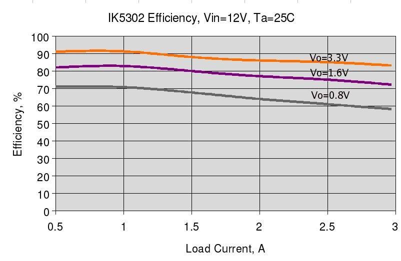
8 Efficiency 8
9 Application Information The basic IK5302 application circuit is show in Figure 1. Component selection is explained below. Input Capacitor The input capacitor must be connected to the V IN pin and GND pin of IK5302 to maintain steady input voltage and filter out the pulsing input current. The voltage rating of input capacitor must be greater than maximum input voltage plus ripple voltage. The input ripple voltage can be approximated by equation below: Since the input current is discontinuous in a buck converter, the current stress on the input capacitor is another concern when selecting the capacitor. For a buck circuit, the RMS value of input capacitor current can be calculated by: For reliable operation and best performance, the input capacitors must have current rating higher than I CIN_RMS at worst operating conditions. Ceramic capacitors are preferred for input capacitors because of their low ESR and high current rating. Depending on the application circuits, other low ESR tantalum capacitor may also be used. When selecting ceramic capacitors, X5R or X7R type dielectric ceramic capacitors should be used for their better temperature and voltage characteristics. Note that the ripple current rating from capacitor manufactures are based on certain amount of life time. Further derating may be necessary in practical design. Inductor The inductor is used to supply constant current to output when it is driven by a switching voltage. For given input and output voltage, inductance and switching frequency together decide the inductor ripple current, which is: The peak inductor current is: High inductance gives low inductor ripple current but requires larger size inductor to avoid saturation. Low ripple current reduces inductor core losses. It also reduces RMS current through inductor and switches, which results in less conduction loss. Usually, peak to peak ripple current on inductor is designed to be 20% to 40% of output current. When selecting the inductor, make sure it is able to handle the peak current without saturation even at the highest operating temperature. The inductor takes the highest current in a buck circuit. The conduction loss on inductor need to be checked for thermal and efficiency requirements. Surface mount inductors in different shape and styles are available from Coilcraft, Elytone and Murata. Shielded inductors are small and radiate less EMI noise. But they cost more than unshielded inductors. The choice depends on EMI requirement, price and size. 9
10 Output Capacitor The output capacitor is selected based on the DC output voltage rating, output ripple voltage specification and ripple current rating. The selected output capacitor must have a higher rated voltage specification than the maximum desired output voltage including ripple. Derating needs to be considered for long term reliability. Output ripple voltage specification is another important factor for selecting the output capacitor. In a buck converter circuit, output ripple voltage is determined by inductor value, switching frequency, output capacitor value and ESR. It can be calculated by the equation below: where, C O is output capacitor value, and ESR CO is the equivalent series resistance of the output capacitor. When low ESR ceramic capacitor is used as output capacitor, the impedance of the capacitor at the switching frequency dominates. Output ripple is mainly caused by capacitor value and inductor ripple current. The output ripple voltage calculation can be simplified to: If the impedance of ESR at switching frequency dominates, the output ripple voltage is mainly decided by capacitor ESR and inductor ripple current. The output ripple voltage calculation can be further simplified to: For lower output ripple voltage across the entire operating temperature range, X5R or X7R dielectric type of ceramic, or other low ESR tantalum are recommended to be used as output capacitors. In a buck converter, output capacitor current is continuous. The RMS current of output capacitor is decided by the peak to peak inductor ripple current. It can be calculated by: Usually, the ripple current rating of the output capacitor is a smaller issue because of the low current stress. When the buck inductor is selected to be very small and inductor ripple current is high, the output capacitor could be overstressed. Loop Compensation The IK5302 employs peak current mode control for easy use and fast transient response. Peak current mode control eliminates the double pole effect of the output L&C filter. It greatly simplifies the compensation loop design. With peak current mode control, the buck power stage can be simplified to be a onepole and onezero system in frequency domain. The pole is the dominant pole can be calculated by: The zero is an ESR zero due to output capacitor and its ESR. It is can be calculated by: where; C O is the output filter capacitor, R L is load resistor value, and ESR CO is the equivalent series resistance of output capacitor. 10
11 The compensation design is actually to shape the converter control loop transfer function to get the desired gain and phase. Several different types of compensation network can be used for the IK5302. In most cases, a series capacitor and resistor network connected to the COMP pin sets the polezero and is adequate for a stable highbandwidth control loop. The compensation network design requires several steps: 1. Crossover frequency choice f C : Normally this is 1/5 to 1/15 of switching frequency. Higher value improve transient response but have bigger noise due to wider frequency of interest. Lower value have lower noise, but slower transient response. Basically 1/10 is a optimal choice for most application. So, for 1.0MHz operation f C =100kHZ. 2. Next step is Rc resistor choice in the compensation network. Value of Rc insure that on crossover frequency loop gain will be equal to unity. We can calculate by the formula: 3. Rc=2*π* f C *Vout*Col(gmea*Vref*gmps) where fc is crossover frequency; Vout is output voltage; Co is output capacitance; Gmea error amplifier transconductance (200uA/V); Vref reference voltage (Vref=0.8); Gmps power stage transconductance (~8.6 A/V); 4. Choose compensation capacitance Cc: Compensation capacitance defined compensation zero which should be placed on output stage pole. It can be defined as below: Cc=Rl*Co/Rc where Rl is load resistance; Co is output capacitance; Rc compensation resistance. 11

12 Application Information DemoBoard Schematic DemoBoard PCB 12
13 NO PARTS NAME SPECIFICATION 1 PCB 2 Manual Working 3 LINE FILTER Spec:FR4 4LAYER HPSCBB1207 2R2M PCB Components List LOCAT NO. UNIT Q'TY VENDOR REMARKS 1 EA L1 1 EA Hwasung coil 4 SMD TYPE 5 CER/CAPACITOR 10uF/25V(1206) C1,C2 2 EA samsungel 6 CER/CAPACITOR 22uF/16V(3225) C7 1 EA samsungel 7 CER/CAPACITOR 100n/50V(0603) C4 1 EA samsungel 8 CER/CAPACITOR 1n/50V(0603) C5 1 EA samsungel 9 CER/CAPACITOR 10n/50V(0603) C6 1 EA samsungel 10 RESISTOR 5K(0603) R5 1 EA samsungel 11 RESISTOR 10KF(0603) R1,R4 2 EA samsungel 12 RESISTOR 31.2KF(0603) R3 1 EA samsungel 13 RESISTOR 30K(0603) R2 1 EA samsungel 14 IC IK5302 U1 1 EA samsungel (1.2X1.2X0.8) SMD/T6A 13
14 Package Dimensions SOP 8 Note: The unit for the outline drawing is mm. 14
AOZ A Synchronous EZBuck TM Regulator. General Description. Features. Applications. Typical Application
 3A Synchronous EZBuck TM Regulator General Description The AOZ303DI is a current-mode step down regulator with integrated high-side NMOS switch and low-side NMOS switch that operates up to 8V. The device
AOZ3019. Not Recommended For New Designs. EZBuck 6 A Synchronous Buck Regulator AOZ3019. General Description. Features.
 EZBuck 6 A Synchronous Buck Regulator General Description The AOZ3019 is a high efficiency, easy to use, 6A synchronous buck regulator. The AOZ3019 works from 4.5V to 18V input voltage range, and provides
2A, 23V, 380KHz Step-Down Converter
 2A, 23V, 380KHz Step-Down Converter General Description The is a buck regulator with a built-in internal power MOSFET. It achieves 2A continuous output current over a wide input supply range with excellent
AOZ3015AI. EZBuck 3 A Synchronous Buck Regulator AOZ3015AI. General Description. Features. Applications. Typical Application
 EZBuck 3 A Synchronous Buck Regulator General Description The AOZ305AI is a high efficiency, easy to use, 3 A synchronous buck regulator. The AOZ305AI works from 4.5 V to 8 V input voltage range, and provides
AOZ3015PI LX. EZBuck 3 A Synchronous Buck Regulator. Features. General Description. Applications. Typical Application AOZ3015PI
 EZBuck 3 A Synchronous Buck Regulator General Description The AOZ305PI is a high efficiency, easy to use, 3 A synchronous buck regulator. The AOZ305PI works from 4.5 V to 8 V input voltage range, and provides
Techcode. 1.6A 32V Synchronous Rectified Step-Down Converte TD1529. General Description. Features. Applications. Package Types DATASHEET
 General Description Features The TD1529 is a monolithic synchronous buck regulator. The device integrates two 130mΩ MOSFETs, and provides 1.6A of continuous load current over a wide input voltage of 4.75V
AOZ6605PI. EZBuck TM 5A Synchronous Buck Regulator. General Description. Features. Applications. Typical Application
 EZBuck TM 5A Synchronous Buck Regulator General Description The AOZ6605PI works from 4.5V to 18V input voltage range, and provides up to 5A of continuous output current with an output voltage adjustable
FEATURES DESCRIPTION APPLICATIONS PACKAGE REFERENCE
 DESCRIPTION The is a monolithic synchronous buck regulator. The device integrates 100mΩ MOSFETS that provide 2A continuous load current over a wide operating input voltage of 4.75V to 25V. Current mode
EUP A,30V,500KHz Step-Down Converter DESCRIPTION FEATURES APPLICATIONS. Typical Application Circuit
 5A,30V,500KHz Step-Down Converter DESCRIPTION The is current mode, step-down switching regulator capable of driving 5A continuous load with excellent line and load regulation. The operates with an input
HM1410 FEATURES APPLICATIONS PACKAGE REFERENCE HM1410
 DESCRIPTION The is a monolithic step-down switch mode converter with a built in internal power MOSFET. It achieves 2A continuous output current over a wide input supply range with excellent load and line
AOZ3011PI EZBuck 3 A Synchronous Buck Regulator
 EZBuck 3 A Synchronous Buck Regulator General Description The AOZ3011PI is a high efficiency, easy to use, 3 A synchronous buck regulator. The AOZ3011PI operates from 4.5 V to 18 V input voltage range,
EUP3410/ A,16V,380KHz Step-Down Converter DESCRIPTION FEATURES APPLICATIONS. Typical Application Circuit
 2A,16V,380KHz Step-Down Converter DESCRIPTION The is a current mode, step-down switching regulator capable of driving 2A continuous load with excellent line and load regulation. The can operate with an
EUP3452A. 2A,30V,300KHz Step-Down Converter DESCRIPTION FEATURES APPLICATIONS. Typical Application Circuit
 2A,30V,300KHz Step-Down Converter DESCRIPTION The is current mode, step-down switching regulator capable of driving 2A continuous load with excellent line and load regulation. The can operate with an input
AOZ3013PI. EZBuck 3 A Synchronous Buck Regulator AOZ3013PI. General Description. Features. Applications. Typical Application
 EZBuck 3 A Synchronous Buck Regulator General Description The AOZ3013PI is a high efficiency, easy to use, 3 A synchronous buck regulator. The AOZ3013PI operates from 4.5 V to 18 V input voltage range,
EUP A,40V,200KHz Step-Down Converter
 3A,40V,200KHz Step-Down Converter DESCRIPTION The is current mode, step-down switching regulator capable of driving 3A continuous load with excellent line and load regulation. The operates with an input
SGM6132 3A, 28.5V, 1.4MHz Step-Down Converter
 GENERAL DESCRIPTION The SGM6132 is a current-mode step-down regulator with an internal power MOSFET. This device achieves 3A continuous output current over a wide input supply range from 4.5V to 28.5V
idesyn id8802 2A, 23V, Synchronous Step-Down DC/DC
 2A, 23V, Synchronous Step-Down DC/DC General Description Applications The id8802 is a 340kHz fixed frequency PWM synchronous step-down regulator. The id8802 is operated from 4.5V to 23V, the generated
Thermally enhanced Low V FB Step-Down LED Driver ADT6780
 Thermally enhanced Low V FB Step-Down LED Driver General Description The is a thermally enhanced current mode step down LED driver. That is designed to deliver constant current to high power LEDs. The
AOZ1019. EZBuck 2A Simple Regulator. Features. General Description. Applications. Typical Application AOZ1019
 EZBuck 2A Simple Regulator General Description The AOZ1019 is a high efficiency, simple to use, 2A buck regulator. The AOZ1019 works from a 4.5V to 16V input voltage range, and provides up to 2A of continuous
3A, 23V, 380KHz Step-Down Converter
 3A, 23V, 380KHz Step-Down Converter General Description The is a buck regulator with a built in internal power MOSFET. It achieves 3A continuous output current over a wide input supply range with excellent
MP9141 FEATURES DESCRIPTION APPLICATIONS PACKAGE REFERENCE
 DESCRIPTION The is a monolithic step-down switch mode converter with a built in internal power MOSFET. It achieves 2A continuous output current over a wide input supply range with excellent load and line
AOZ1240 EZBuck 2A Simple Buck Regulator
 EZBuck 2A Simple Buck Regulator General Description The AOZ1240 is a high efficiency, simple to use, 2A buck regulator flexible enough to be optimized for a variety of applications. The AOZ1240 works from
AOZ6623DI. EZBuck TM 3A Synchronous Buck Regulator. General Description. Features. Applications. Typical Application
 EZBuck TM 3A Synchronous Buck Regulator General Description The AOZ6623DI is a high efficiency, easy to use, 3A synchronous buck regulator. The AOZ6623DI works from 4.5V to 18V input voltage range, and
AOZ3024PI. EZBuck 3 A Synchronous Buck Regulator AOZ3024PI. General Description. Features. Applications. Typical Application
 EZBuck 3 A Synchronous Buck Regulator General Description The AOZ3024PI is a high efficiency, easy to use, 3 A synchronous buck regulator. The AOZ3024PI works from 4.5 V to 18 V input voltage range, and
SGM6232 2A, 38V, 1.4MHz Step-Down Converter
 GENERAL DESCRIPTION The is a current-mode step-down regulator with an internal power MOSFET. This device achieves 2A continuous output current over a wide input supply range from 4.5V to 38V with excellent
MP1482 2A, 18V Synchronous Rectified Step-Down Converter
 The Future of Analog IC Technology MY MP48 A, 8 Synchronous Rectified Step-Down Converter DESCRIPTION The MP48 is a monolithic synchronous buck regulator. The device integrates two 30mΩ MOSFETs, and provides
AOZ1284 EZBuck 4A Simple Buck Regulator
 EZBuck 4A Simple Buck Regulator General Description The AOZ284 is a high voltage, high efficiency, simple to use, 4A buck regulator optimized for a variety of applications. The AOZ284 works from a 3.0V
AOZ1280. EZBuck 1.2 A Simple Buck Regulator AOZ1280. Features. General Description. Applications. Typical Application
 EZBuck 1.2 A Simple Buck Regulator General Description The AOZ1280 is a high efficiency, simple to use, 1.2 A buck regulator which is flexible enough to be optimized for a variety of applications. The
AOZ1025D. Not Recommended For New Designs. EZBuck 8A Synchronous Buck Regulator. Features. General Description. Applications. Typical Application
 EZBuck 8A Synchronous Buck Regulator General Description The AOZ025D is a high efficiency, simple to use, buck regulator, capable of up to 8A with an external low side MOSFET. The AOZ025D works from a
ADT7351. General Description. Applications. Features. Typical Application Circuit. Oct / Rev0.
 General Description The ADT735 is a step-down converter with integrated switching MOSFET. It operates wide input supply voltage range from 4.5 to 28 with 3A continuous output current. It includes current
AOZ1056 EZBuck 2A Simple Buck Regulator
 EZBuck 2A Simple Buck Regulator General Description The AOZ056 is a high efficiency, simple to use, 2A buck regulator. The AOZ056 works from a 4.5V to 6V input voltage range, and provides up to 2A of continuous
AOZ1081 EZBuck 1.8A High Efficiency Constant Current Regulator for LEDs
 EZBuck 1.8A High Efficiency Constant Current Regulator for LEDs General Description The AOZ1081 is a high efficiency, simple to use, 1.8A buck regulator for White LED. The AOZ1081 works from a 4.5V to
NX7101 2A, High Voltage Synchronous Buck Regulator
 is a 340kHz fixed frequency, current mode, PWM synchronous buck (step-down) DC- DC converter, capable of driving a 2A load with high efficiency, excellent line and load regulation. The device integrates
AOZ1018. EZBuck 2A Simple Regulator AOZ1018. General Description. Features. Applications. Typical Application
 EZBuck 2A Simple Regulator General Description The AOZ08 is a high efficiency, simple to use, 2A buck regulator. The AOZ08 works from a 4.5V to 6V input voltage range, and provides up to 2A of continuous
AOZ1022DI-01 EZBuck 3A Synchronous Buck Regulator
 EZBuck 3A Synchronous Buck Regulator General Description The AOZ1022DI-01 is a synchronous high efficiency, simple to use, 3A buck regulator. The AOZ1022DI-01 works from a 4.5V to 16V input voltage range,
A7221A DC-DC CONVERTER/BUCK (STEP-DOWN) 600KHz, 16V, 2A SYNCHRONOUS STEP-DOWN CONVERTER
 600KHz, 16V, 2A SYNCHRONOUS STEP-DOWN CONVERTER") DESCRIPTION The is a fully integrated, high efficiency 2A synchronous rectified step-down converter. The operates at high efficiency over a wide output current load range. This device offers two operation
DESCRIPTION The is a fully integrated, high efficiency 2A synchronous rectified step-down converter. The operates at high efficiency over a wide output current load range. This device offers two operation
MP2305 2A, 23V Synchronous Rectified Step-Down Converter
 The Future of Analog IC Technology MP305 A, 3 Synchronous Rectified Step-Down Converter DESCRIPTION The MP305 is a monolithic synchronous buck regulator. The device integrates 30mΩ MOSFETS that provide
DESCRIPTION FEATURES APPLICATIONS TYPICAL APPLICATION. 500KHz, 18V, 2A Synchronous Step-Down Converter
 DESCRIPTION The is a fully integrated, high-efficiency 2A synchronous rectified step-down converter. The operates at high efficiency over a wide output current load range. This device offers two operation
A7221 DC-DC CONVERTER/ BUCK (STEP-DOWN) HIGH EFFICIENCY FAST RESPONSE, 2A, 16V INPUT SYNCHRONOUS STEP-DOWN CONVERTER
 HIGH EFFICIENCY FAST RESPONSE, 2A, 16V INPUT SYNCHRONOUS STEP-DOWN CONVERTER") DESCRIPTION develops high efficiency synchronous step-down DC-DC converter capable of delivering 2A load current. operates over a wide input voltage range from 6V to 16V and integrates main switch and
DESCRIPTION develops high efficiency synchronous step-down DC-DC converter capable of delivering 2A load current. operates over a wide input voltage range from 6V to 16V and integrates main switch and
Pin Assignment Pin No. Pin Name Descripition 1 BS High-Side Gate Drive Boost Input. BS supplies the drive for the highside N-Channel MOSFET switch. Co
 Description The is a monolithic synchronous buck regulator. The device integrates MOSFETS that provide 2A continuous load current over a wide Operating input voltage of 4.7V to 18V. Current mode control
AT V,3A Synchronous Buck Converter
 FEATURES DESCRIPTION Wide 8V to 40V Operating Input Range Integrated 140mΩ Power MOSFET Switches Output Adjustable from 1V to 25V Up to 93% Efficiency Internal Soft-Start Stable with Low ESR Ceramic Output
2A, 23V, 380KHz Step-Down Converter
 2A, 23V, 380KHz Step-Down Converter FP6182 General Description The FP6182 is a buck regulator with a built in internal power MOSFET. It achieves 2A continuous output current over a wide input supply range
SGM6130 3A, 28.5V, 385kHz Step-Down Converter
 GENERAL DESCRIPTION The SGM6130 is a current-mode step-down regulator with an internal power MOSFET. This device achieves 3A continuous output current over a wide input supply range from 4.5 to 28.5 with
PRODUCTION DATA SHEET
 is a 340kHz fixed frequency, current mode, PWM synchronous buck (step-down) DC- DC converter, capable of driving a 3A load with high efficiency, excellent line and load regulation. The device integrates
AOZ1083 AOZ A Buck LED Driver. General Description. Features. Applications. Typical Application
 1.2 A Buck LED Driver General Description The AOZ1083 is a high efficiency, simple to use, 1.2 A buck HB LED driver optimized for general lighting applications. The AOZ1083 operates from a 3 V to 26 V
AOZ1015 EZBuck 1.5A Non-Synchronous Buck Regulator
 EZBuck.5A Non-Synchronous Buck Regulator General Description The AOZ05 is a high efficiency, simple to use,.5a buck regulator. The AOZ05 works from a 4.5V to 6V input voltage range, and provides up to.5a
AOZ1017A EZBuck 3A Simple Regulator
 EZBuck 3A Simple Regulator General Description The AOZ07A is a high efficiency, simple to use, 3A buck regulator. The AOZ07A works from a 4.5V to 6V input voltage range, and provides up to 3A of continuous
UNISONIC TECHNOLOGIES CO., LTD UCC36351 Preliminary CMOS IC
 UNISONIC TECHNOLOGIES CO., LTD UCC36351 Preliminary CMOS IC 36V SYNCHRONOUS BUCK CONVERTER WITH CC/CV DESCRIPTION UTC UCC36351 is a wide input voltage, high efficiency Active CC step-down DC/DC converter
340KHz, 36V/2.5A Step-down Converter With Soft-Start
 340KHz, 36V/2.5A Step-down Converter With Soft-Start General Description The contains an independent 340KHz constant frequency, current mode, PWM step-down converters. The converter integrates a main switch
Analog Technologies. ATI2202 Step-Down DC/DC Converter ATI2202. Fixed Frequency: 340 khz
 Step-Down DC/DC Converter Fixed Frequency: 340 khz APPLICATIONS LED Drive Low Noise Voltage Source/ Current Source Distributed Power Systems Networking Systems FPGA, DSP, ASIC Power Supplies Notebook Computers
AOZ1282DI. EZBuck 1.2A Simple Buck Regulator. General Description. Features. Applications. Typical Application AOZ1282DI
 EZBuck 1.2A Simple Buck Regulator General Description The AOZ1282DI is a high efficiency, simple to use, 1.2A buck regulator flexible enough to be optimized for a variety of applications. The AOZ1282DI
EUP A,30V,1.2MHz Step-Down Converter DESCRIPTION FEATURES APPLICATIONS. Typical Application Circuit
 1.2A,30V,1.2MHz Step-Down Converter DESCRIPTION The is current mode, step-down switching regulator capable of driving 1.2A continuous load with excellent line and load regulation. The can operate with
AT V 5A Synchronous Buck Converter
 FEATURES DESCRIPTION Wide 8V to 38V Operating Input Range Integrated 80mΩ Power MOSFET Switches Output Adjustable from VFB(1V) to 20V Up to 95% Efficiency Internal Soft-Start Stable with Low ESR Ceramic
AT V Synchronous Buck Converter
 38V Synchronous Buck Converter FEATURES DESCRIPTION Wide 8V to 38V Operating Input Range Integrated two 140mΩ Power MOSFET Switches Feedback Voltage : 220mV Internal Soft-Start / VFB Over Voltage Protection
AOZ1281. EZBuck 1.8 A Simple Buck Regulator AOZ1281. General Description. Features. Applications. Typical Application
 EZBuck 1.8 A Simple Buck Regulator General Description The AOZ1281 is a high efficiency, simple to use, 1.8 A buck regulator flexible enough to be optimized for a variety of applications. The AOZ1281 works
LSP5502 2A Synchronous Step Down DC/DC Converter
 FEATURES 2A Output Current Wide 4.5V to 27V Operating Input Range Integrated 20mΩ Power MOSFET Switches Output Adjustable from 0.925V to 24V Up to 96% Efficiency Programmable Soft-Start Stable with Low
ZA3020LV 2A Step-Down,PWM,Switch-Mode DC-DC Regulator
 General Description The is a monolithic step-down switch-mode regulator with internal Power MOSFETs. It achieves 2A continuous output current over a wide input supply range with excellent load and line
EM5812/A. 12A 5V/12V Step-Down Converter. Applications. General Description. Pin Configuration. Ordering Information. Typical Application Circuit
 12A 5V/12V Step-Down Converter General Description is a synchronous rectified PWM controller with a built in high-side power MOSFET operating with 5V or 12V supply voltage. It achieves 10A continuous output
HM2259D. 2A, 4.5V-20V Input,1MHz Synchronous Step-Down Converter. General Description. Features. Applications. Package. Typical Application Circuit
 HM2259D 2A, 4.5V-20V Input,1MHz Synchronous Step-Down Converter General Description Features HM2259D is a fully integrated, high efficiency 2A synchronous rectified step-down converter. The HM2259D operates
AIC2858 F. 3A 23V Synchronous Step-Down Converter
 3A 23V Synchronous Step-Down Converter FEATURES 3A Continuous Output Current Programmable Soft Start 00mΩ Internal Power MOSFET Switches Stable with Low ESR Output Ceramic Capacitors Up to 95% Efficiency
LSP A 23V Synchronous Buck Converter. General Description. Features. Applications. LSP5526 Rev of /8/1.
 General Description The LSP5526 is a monolithic synchronous buck regulator. The device integrates 95mΩ MOSFETS that provide 2A continuous load current over a wide operating input voltage of 4.5V to 23V.
23V, 2A, 600KHz Asynchronous Synchronous Step-Down DC/DC Converter
 23V, 2A, 600KHz Asynchronous Synchronous StepDown DC/DC Converter Description The is a monolithic stepdown switch mode converter with a builtin power MOSFET. It achieves 2A output current over a wide input
Alfa-MOS Technology. AF KHz, 3.0A / 23V Asynchronous Step-Down Converter
 General Description is a high efficiency step down DC/DC converter operated with current mode and constant frequency. can supply 3A of load current from 4.75V to 23V input voltage. The output voltage can
23V, 3A, 340KHz Synchronous Step-Down DC/DC Converter
 23V, 3A, 340KHz Synchronous Step-Down DC/DC Converter Description The is a synchronous step-down DC/DC converter that provides wide 4.5V to 23V input voltage range and 3A continuous load current capability.
MP2313 High Efficiency 1A, 24V, 2MHz Synchronous Step Down Converter
 The Future of Analog IC Technology MP2313 High Efficiency 1A, 24V, 2MHz Synchronous Step Down Converter DESCRIPTION The MP2313 is a high frequency synchronous rectified step-down switch mode converter
30V, 3.1A Monolithic Step-Down Switching Regulator. C5 100nF/25V 5 FB COMP GND 4. Fig. 1 Schematic 60.00%
 30V, 3.1A Monolithic Step-Down Switching Regulator 1 Features 3.1A continuous output current capability 6.5V to 30V wide operating input range with input Over Voltage Protection Integrated 36V, 79mΩ high
UNISONIC TECHNOLOGIES CO., LTD UD38252
 UNISONIC TECHNOLOGIES CO., LTD UD38252 38V SYNCHRONOUS BUCK CONVERTER WITH CC/CV DESCRIPTION UTC UD38252 is a wide input voltage, high efficiency Active CC step-down DC/DC converter that operates in either
MP2307 3A, 23V, 340KHz Synchronous Rectified Step-Down Converter
 The Future of Analog IC Technology TM TM MP307 3A, 3, 340KHz Synchronous Rectified Step-Down Converter DESCRIPTION The MP307 is a monolithic synchronous buck regulator. The device integrates 00mΩ MOSFETS
HM V, 3.1A Monolithic Step-Down Switching Regulator in TSOT Features. 2 Applications. 3 Description. 4 Typical Application Schematic
 30V, 3.1A Monolithic Step-Down Switching Regulator in TSOT23-8 1 Features 3.0A continuous output current capability 6.5V to 30Vwide operating input range with input Over Voltage Protection Integrated 36V,
MP1484 3A, 18V, 340KHz Synchronous Rectified Step-Down Converter
 The Future of Analog IC Technology MP484 3A, 8, 340KHz Synchronous Rectified Step-Down Converter DESCRIPTION The MP484 is a monolithic synchronous buck regulator. The device integrates top and bottom 85mΩ
Low-Noise 4.5A Step-Up Current Mode PWM Converter
 Low-Noise 4.5A Step-Up Current Mode PWM Converter FP6298 General Description The FP6298 is a current mode boost DC-DC converter. It is PWM circuitry with built-in 0.08Ω power MOSFET make this regulator
ACE726C. 500KHz, 18V, 2A Synchronous Step-Down Converter. Description. Features. Application
 Description The is a fully integrated, high-efficiency 2A synchronous rectified step-down converter. The operates at high efficiency over a wide output current load range. This device offers two operation
MP2314 High Efficiency 2A, 24V, 500kHz Synchronous Step Down Converter
 The Future of Analog IC Technology MP2314 High Efficiency 2A, 24V, 500kHz Synchronous Step Down Converter DESCRIPTION The MP2314 is a high frequency synchronous rectified step-down switch mode converter
UNISONIC TECHNOLOGIES CO., LTD
 UNISONIC TECHNOLOGIES CO., LTD 38V 5A SYNCHRONOUS BUCK CONVERTER DESCRIPTION The UTC UD38501 is a monolithic synchronous buck regulator. The device integrates internal high side and external low side power
10A Current Mode Non-Synchronous PWM Boost Converter
 10A Current Mode Non-Synchronous PWM Boost Converter General Description The is a current mode boost DC-DC converter. It is PWM circuitry with built-in 15mΩ power MOSFET make this regulator highly power
3A, 36V, Step-Down Converter
 3A, 36, Step-Down Converter FP6150 General Description The FP6150 is a buck regulator with a built in internal power MOSFET. It achieves 3A continuous output current over a wide input supply range with
340KHz, 3A, Asynchronous Step-Down Regulator
 340KHz, 3A, Asynchronous Step-Down Regulator FP6116 General Description The FP6116 is a buck switching regulator for wide operating voltage application fields. The FP6116 includes a high current P-MOSFET,
4.5V to 32V Input High Current LED Driver IC For Buck or Buck-Boost Topology CN5816. Features: SHDN COMP OVP CSP CSN
 4.5V to 32V Input High Current LED Driver IC For Buck or Buck-Boost Topology CN5816 General Description: The CN5816 is a current mode fixed-frequency PWM controller for high current LED applications. The
340KHz, 2A, Asynchronous Step-Down Regulator
 340KHz, 2A, Asynchronous Step-Down Regulator FP6115 General Description The FP6115 is a buck switching regulator for wide operating voltage application fields. The FP6115 includes a high current P-MOSFET,
TS3552 2A/350kHz Synchronous Buck DC/DC Converter
 SOP-8 Pin Definition: 1. BS 8. SS 2. VIN 7. EN 3. SW 6. COMP 4. GND 5. FB General Description The TS3552 is a synchronous step-down DC/DC converter that provides wide 4.75V to 23V input voltage range and
HF A 27V Synchronous Buck Converter General Description. Features. Applications. Package: TBD
 General Description The is a monolithic synchronous buck regulator. The device integrates 80 mω MOSFETS that provide 4A continuous load current over a wide operating input voltage of 4.5V to 27V. Current
December 2010 Rev FEATURES. Fig. 1: XRP7664 Application Diagram
 December 2010 Rev. 1.1.0 GENERAL DESCRIPTION The XRP7664 is a synchronous current-mode PWM step down (buck) regulator capable of a constant output current up to 2Amps. A wide 4.75V to 18V input voltage
General Description BS SW LSP5526. C4 1.6nF R3 C5 NC 10K. shows a sample LSP5526 application circuit generating 5V/2A output
 Features 2A Output urrent Wide 4.5V to 23V Operating Input Range Integrated Power MOSFET Switches Output Adjustable from 0.925V to 18V Up to 96% Efficiency Programmable Soft-Start Stable with Low ESR eramic
MP2354 2A, 23V, 380KHz Step-Down Converter
 The Future of Analog IC Technology MP2354 2A, 23V, 380KHz Step-Down Converter DESCRIPTION The MP2354 is a monolithic step down switch mode converter with a built in internal power MOSFET. It achieves 2A
AOZ1242 EZBuck 3A Simple Buck Regulator
 EZBuck 3A Simple Buck Regulator General Description The AOZ1242 is a high efficiency, simple to use, 3A buck regulator flexible enough to be optimized for a variety of applications. The AOZ1242 works from
MP1570 3A, 23V Synchronous Rectified Step-Down Converter
 Monolithic Power Systems MP570 3A, 23 Synchronous Rectified Step-Down Converter FEATURES DESCRIPTION The MP570 is a monolithic synchronous buck regulator. The device integrates 00mΩ MOSFETS which provide
1.2A, 23V, 1.4MHz Step-Down Converter
 1.2A, 23, 1.4MHz Step-Down Converter General Description The is a buck regulator with a built-in internal power MOSFET. It can provide 1.2A continuous output current over a wide input supply range with
1.5MHz, 1.5A Step-Down Converter
 1.5MHz, 1.5A Step-Down Converter General Description The is a 1.5MHz constant frequency current mode PWM step-down converter. It is ideal for portable equipment which requires very high current up to 1.5A
EUP V/12V Synchronous Buck PWM Controller DESCRIPTION FEATURES APPLICATIONS. Typical Application Circuit. 1
 5V/12V Synchronous Buck PWM Controller DESCRIPTION The is a high efficiency, fixed 300kHz frequency, voltage mode, synchronous PWM controller. The device drives two low cost N-channel MOSFETs and is designed
24V, 2A, 340KHz Synchronous Step-Down DC/DC Converter
 24V, 2A, 340KHz Synchronous Step-Down DC/DC Converter Product Description The is a synchronous step-down DC/DC converter that provides wide 4.5V to 24V input voltage range and 2A continuous load current
TFT-LCD DC/DC Converter with Integrated Backlight LED Driver
 TFT-LCD DC/DC Converter with Integrated Backlight LED Driver Description The is a step-up current mode PWM DC/DC converter (Ch-1) built in an internal 1.6A, 0.25Ω power N-channel MOSFET and integrated
FP A Current Mode Non-Synchronous PWM Boost Converter
 10A Current Mode Non-Synchronous PWM Boost Converter General Description The is a current mode boost DC-DC converter. It is PWM circuitry with built-in 15mΩ power MOSFET make this regulator highly power
AMS2115 FAST TRANSIENT RESPONSE LDO CONTROLLER
 FAST TRANSIENT RESPONSE LDO CONTROLLER General Description The AMS5 is a single IC controller that drives an external N Channel MOSFET as a source follower to produce a fast transient response, low dropout
MP1472 2A, 18V Synchronous Rectified Step-Down Converter
 The Future of Analog IC Technology MP472 2A, 8 Synchronous Rectified Step-Down Converter DESCRIPTION The MP472 is a monolithic synchronous buck regulator. The device integrates a 75mΩ highside MOSFET and
SPPL12420RH. 2 A Synchronous Rectified Step-Down Converter FEATURES DESCRIPTION RADIATION HARDNESS APPLICATIONS
 FEATURES 2 A continuous output current Input voltage capability (derating reference): 24 V Minimum input voltage: 4.5 V Minimum output voltage: 0.923 V Latch-up immune (fully isolated SOI technology) Hermetic
AME. 3A, 300KHz ~ 2MHz Synchronous Rectified Step-Down Converter AME5287. General Description. Typical Application. Features.
 587 General Description Typical Application The 587 is a Synchronous Rectified Step-Down Converter with internal power MOSFETs. It achieves 3A continuous output current over a wide switching frequency
EUP A, Synchronous Step-Down Converter DESCRIPTION FEATURES APPLICATIONS. Typical Application Circuit
 2A, Synchronous Step-Down Converter DESCRIPTION The is a 1 MHz fixed frequency synchronous, current-mode, step-down dc-dc converter capable of providing up to 2A output current. The operates from an input
MP2303 3A, 28V, 340KHz Synchronous Rectified Step-Down Converter
 MP2303 3A, 28V, 340KHz Synchronous Rectified Step-Down Converter TM The Future of Analog IC Technology DESCRIPTION The MP2303 is a monolithic synchronous buck regulator. The device integrates power MOSFETS
MP2225 High-Efficiency, 5A, 18V, 500kHz Synchronous, Step-Down Converter
 The Future of Analog IC Technology DESCRIPTION The MP2225 is a high-frequency, synchronous, rectified, step-down, switch-mode converter with built-in power MOSFETs. It offers a very compact solution to
MP2355 3A, 23V, 380KHz Step-Down Converter
 The Future of Analog IC Technology MP2355 3A, 23, 380KHz Step-Down Converter DESCRIPTION The MP2355 is a step-down regulator with a built in internal Power MOSFET. It achieves 3A continuous output current