EFM electronics for music
|
|
|
- Olivia Cooper
- 6 years ago
- Views:
Transcription

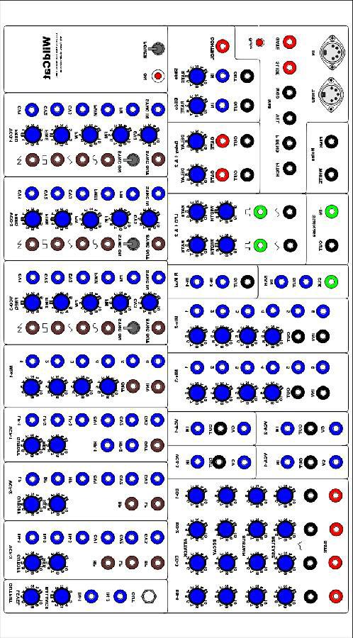
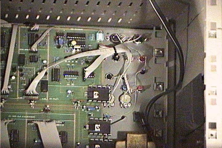
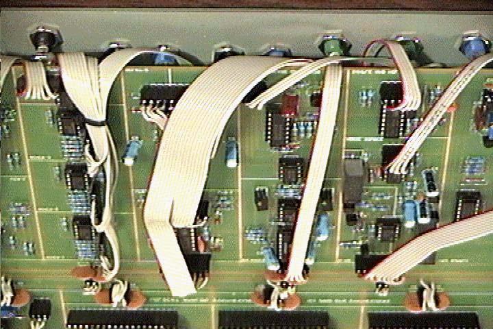
1 The is a modular system designed to be flexible enough to to build many types of synthesizers as well as remain unique. The most comprehensive system is naturally the most expensive to build. However the board can also be used to construct a much less expensive synthesizer. A full blown Modular could cost more than $1000. The Modular-1 was close to $600. About $100 went for ribbon cable and headerconnectors. If you want to direct-wire and you already have or build your own case you can cut it down to under $500. It's all a matter of how much of the board you utilise and what type of hardware you use. Something simple could be constructed for under $300. People who elect to direct-wire should note that it makes it impossible to remove the board. As you read through this document you will see block symbols representing WildCat modules. This system allows WildCat builders to block-diagram their synthesizer. Say you would like plan your synth out before you build it. Now there's no reason to redraw all those schematics to fit your special purpose. Or you want build a web page to show off your synth when it's finished. Usually you could not use EFM schematics or drawings on your site but I would really like to encourage the free use of these diagrams.
2
3 Power Supply The on-board 2 amp +/ volt power supply. The power rails run down the center of the board. There are 2 access headers to the right and another to the left. These are for testing purposes during construction and can be used for future expansion. Description The WildCat power supply provides plus and minus 12VDC. When S1 is closed line level AC is applied to the 24V center tapped transformer. R1 and LED1 form a power on indicator. D1-4 form a full wave rectifier supplying about +/- 18VDC at filter capacitors C1 and C2. U1 is a variable-output positive voltage-regulator. R2 and T1 form a voltage divider C4 is used as a capacitance multiplier. The voltage at the R2-T1 junction determine the regulators output voltage. D5 and D6 are for short circuit protection. Likewise U2 is a variableoutput negative voltage-regulator. R3 and T2 form a voltage divider and C3 is used as a capacitance multiplier. D7 and D8 are for short circuit protection.
4 Parts T1 24VCT Transformer (1) S1 SPST Power Switch (1) R1 2.2K 1% Resistor (1 R2.R3 120 Ohm 1% Resistor (2) T1,T2 5K 10T Trimmer (2) C1,C2 1000uF 35V Electrolytic Capacitor (2) C3,C4,C5,C6 10uF 35V Electrolytic Capacitor (4) D1-D8 1N4001 Diode (8) U1 LM317 (1) U2 LM337 (1) Setup Equipment: Digital Multimeter Hook up a power LED. TIP: I used a PC-board header connector and soldered an LED to it so that I could remove it after testing. There are two 3-terminal power headers on the power supply rails labelled +, -, and GND. Set your meter to DC-Voltage and attach your probes. Turn S1 on and look for DC voltage at the power header. You should see something. If not check for DC voltage at D1 and D4. TIP: Use meter probes with removable miniclips. It's so much easier than trying to hold probes while adjusting trimmers. Adjust T1 for +12V and T2 for -12V.
5 Midi to CV Converter Analog synthesizers are controlled by compatible control-voltages. CV - A control voltage is any voltage used to alter the operating parameters of a module. This can range from -V to +V. Gate - Simply on and off. The time was when playing a analog synthesizers involved performing on analogcontrollers. Every piece had it's own keyboard and there were all sorts of standards. Interfacing was a mess and you could forget about serious sequencing. The Midi to CV converter allows you to retain the flavor and feel of analog control using midi enabled devices. Inputs: Midi In Outputs: Midi Thru Pitch - Note Pitch Bend - PB Wheel Velocity - Note Pressure Gate - Note On-Off Mod - Mod Wheel Glide - Whenever more than one key is pressed
6 Description The midi to CV converter uses a 7805 regulator for its +5V supply C1,C2 and C3 are bypass capacitors for voltage regulator U1. Midi is transmitted and received on a closed current loop U2 is a optical coupling device that converts the I/O state on the current loop into serial data the PIC microprocessor U3 can understand. The PIC puts the serial data together and uses the instruction to do a couple of things seemingly simultaneously. It seems simultaneous because the PIC is so fast however it does all of this one step at a time. Q1, Q2 form a non-inverting buffer that provides the midithru signal. Midi data, depending of the transmitting device can handle a lot of information we don't necessarily need to control an analog synthesizer and that's good because it makes doing the job with a low cost PIC possible. We can get by with fairly minimal set of controls.
7 Pitch Pitch Bend Velocity Gate Mod Glide The PIC loads the correct number into the DAC digital to analog converter U4 to generate a voltage that corresponds to the midi message received. Then selects which output is active by strobing the demux U5's select pins through the Q3-Q5 inverter-buffers. When one of the outputs goes high the voltage is sampled and held by capacitors C9-C14 until it is refreshed. U8a is the DAC output amp and U8b is the DAC voltage reference amplifier. NOTE: R1 is part of the power supply and not shown here. Parts C1-C2 0.1uF Ceramic Capacitor 2 C4 10uF@16V 1 C5,C6 22pF Ceramic Capacitor 2 C7 10pF Ceramic Capacitor 1 C8.01uF Poly Capacitor 1 C9-C14 0.1uF Mono Capacitor 6 R2,R9,R Ohm 1% Resistor 3 R3,R5,R16-R25 10K 1% Resistor 12 R4 1K 1% Resistor 1 R6,R7,R8 3.3K 1% Resistor 3 R11-R14,R15 4.7K 1% Resistor 5 R26 47K 1% Resistor 1 R27 2.2K 1% Resistor 1 T1 50K 10T Trimmer 1 Q1,Q3-Q6 2N Q2 2N U V Voltage Reg 1 U2 6N138 1 U3 PIC16F84 1 U4 AD U5 CD U6 LM358 1 U9 TLO72 2 U7 LM336Z 5.0V 1 U8 TLO74 1 S2 4 Position Dip Switch 1 J1,J2 5 Pin Din Panel Mount Jack 2 Setup To generate a 1V/Octave scale the DAC needs the correct reference voltage. Adjust Trimmer T1 until the voltage on U4, pin-4 is V.
8 Glide The Glide or Lag module is a variable frequency low-pass filter. As the cutoff frequency is lowered the chargetime increases and sharp changes in voltage are smoothed. Generally used for pitch-lag (portamento) and smoothing the sample & hold output. It's called glide because it smoothes the transition from one note to another. Effectively gliding from one note to the next note played. Input: CV - In Output: CV - Out Description Voltage on the input charges C3. P1 controls the charge rate. Parts C1,C2 0.1uF Ceramic Capacitor C3 1.0uF Mono Capacitor R1 1K U1 1/2 TLO72
9 Slide The Slide module is much like the Glide module, performing the same sort of function it is however gated. Meaning that the preset lag time is bypassed unless the control input is held high or a gate voltage is present. Input: CV - In Rate - Lag Time Gate - On/Off Time Output: CV - Out Description P1 controls the charge rate of C3. Q1 is a bypass switch for P1. Q2 is a inverter, if the gate is low the collector is high holding Q3 on. If Q3 is on the collector voltage is low and Q1 is on or shorted, closing the circuit across P1. Removing P1 from the signal path. When a gate voltage turns Q2 on the collector is low. Q3s turns off, the collector goes high turning Q1 off. If Q3 is off or open P1 is inserted into the signal path and controls the charge-rate. Parts C1 1.0uF Mono Capacitor R1 1K 1% Metal Film Resistor R2 100K 1% Metal Film Resistor R3,R4,R5 10K 1% Metal Film Resistor R6,* 1M 1% Metal Film Resistor P1 1M Potentiometer D1,D2 1N4148 Diode Q1 2N5460 P-Fet Transistor Q2,Q2 2N3904 NPN Transistor U1 1/2 TLO72
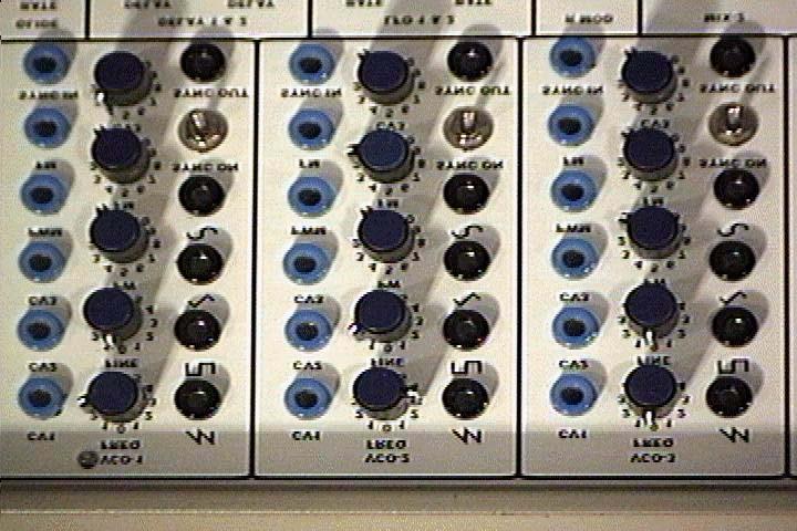
10 VCOs 1-3 The voltage controlled oscillators are generally used to generate audio range signals but can easily be tuned to produce low frequency voltage for modulation purposes. There are simultaneous saw, pulse, triangle and sine outputs. The FM input is a dedicated audio range input for high frequency modulation. It is used to produce ringing or bell like sounds. The Sync output is not usually used because sync can be obtained from the Saw or Pulse outputs. It produces a very thin pulse that in addition to sync can be used as a trigger other devices or modules. Inputs: CV1 - CV3-1 volt per octave CV inputs. CV4 - Frequency CV CV5 - Fine Tune CV FM - Audio Mod PW - Pulse Width PWM - Pulse Width Mod Sync - Sync In Note: Must be connected to -12V when not in use. Outputs: Saw Pulse Triangle Sine Sync Description U1 and U2 from a linear voltage to exponential current sink. As current flows from the +V source C5 starts to charge. When the voltage at the output of buffer (U3a) reaches the threshold level of the comparator (U4a) it turns on. This turns Q1 on and shorts C5 resetting it and the cycle begins again. This oscillation forms a sawtooth waveform on the output of buffer (U3a) An external input on the gate of the synchronisation transistor (Q2) causes the transistor to turn off and on shorting C5 regardless of whether U4a is on. Oscillation occurs in sync with the controlling oscillator. An FM input causes the oscillator center frequency to change with the signal amplitude or Frequency Modulates the exponential converter. The sawtooth waveform is applied to the base of Q3. Q3 is a phase splitter and U3b combines the signals to form a triangle waveform. The sawtooth waveform is also applied to the non-inverting input of comparator U4b. U4b is biased through R28 so that it turns on as soon as the voltage starts to rise at the output of U3a. The output of U4b is a variable pulse waveform A voltage applied to U4a's inverting input changes the duty cycle altering the pulse width. The Sine output is formed by overdriving the input of Operational Transconductance Amplifier U6. Note: R27 is not used
11
12 Parts C1,C2 0.1uF Ceramic Capacitor 2 C3,C4,C7 100pF Ceramic Capacitor 3 C5 0.01uF Mono Capacitor 1 C6 470pF Ceramic Capacitor 1 R1,R2,R3,R6,R29, R30,R32,R37 100K 1% Metal Film Resistor 9 R4 330K 1% Metal Film Resistor 1 R5,R10,R17 1M 1% Metal Film Resistor 3 R7,R8,R28,R33,R35 22K 1% Metal Film Resistor 5 R9 1K Tempco 1 R11,R13,R14.R15,R16, R19,R21,R22,R23, R24,R26 10K 1% Metal Film Resistor 11 R12 470K 1% Metal Film Resistor 1 R18,R31 2.2K 1% Metal Film Resistor 2 R20 60K 1% Metal Film Resistor 1 R25,R34,R36,R40 1K 1% Metal Film Resistor 4 R28 82K 1% Metal Film Resistor 1 R38 220K 1% Metal Film Resistor 1 R39 39K 1% Metal Film Resistor 1 T1,T2,T4 50K 10T Trimmer 3 T2 10K 10T Trimmer 1 P1,2,3,4,5 50K Potentiometer 5 Q1,Q2 J112 N-Fet Transistor 2 Q3 2N3904 NPN Transistor 1 U1,U3,U5 TLO72 Dual Opamp 3 U2 LM3046 Transistor Array 1 U4 LM393 Dual Comparator 1 Setup If Q2 is installed make sure Pad-N is connected to -V. Turn all trimmers to their center positions. Attach a 50K Pulse-Width pot to pad R. Set the PW pot to 50% Attach header pin-p to a monitor amp with a level control and turn it way down. Hook up your midi keyboard to the midi in on the midi converter. Attach a jumper from the midi converters pitch output to header pin-c Turn the unit on and check for +V (U1 Pin-8) and -V (U1 Pin-4) Adjust T6 until the output is somewhere around 440Hz TIP: If you have a mute controller you can use a guitar tuning fork. Play low octave apart D notes and adjust T1 until they are in tune. Play high octave apart D notes and adjust T2 until they are in tune. TIP: You may have to go back and forth between T1 and T2 a few times to get it right. When the oscillator is in tune with itself re-adjust T6 for 440Hz Check the output pins B- Tri Q- Pulse P- Ramp A-Sine for signals. Tip: If you don't have a scope use your monitor amp. Adjust T3 for the best looking/sounding sine.
13 Mixer/Inverters 1-3 There are three 6-input mixers that can be used for audio, CV or a combination of both. There are normal and inverted outputs. Inputs: Audio and/or CV inputs Outputs: Normal Inverted Description When signals are present on the inputs U1a adds them together and outputs the inverted sum of all inputs. U1b is a simple inverting signal. Parts R1-R9 100K 1% Metal Film Resistor 9 U1 TLO72 Dual Opamp 1
14 VCF-1 VCF-1 is a 4-pole Moog type transistor ladder with low-pass and high-pass inputs. Notch can be obtained by splitting the input between both high and low inputs. This filter features voltage controlled resonance and several dedicated mixers. Inputs: HP In 1-2 LP In 1-3 Frequency CV 1-3 Cutoff parameter Resonance parameter Resonance CV Outputs: Audio Out Description due to temperature variations. The voltage applied to the base of the exponential-transistor causes a exponential collector current sink that's applied to the transistor ladder through R34. The ladder transistors are biased at increasingly positive potentials by the voltage divider string R14-18 and R35. The bottom pair of transistors split the current supplied to R34 into equal parts when there is no audio on the base of the U1 (3,4,5) transistor. When audio is present both left and right sides of the ladder are modulated inversely.as current flow increases the collector impedance of the ladder transistors is decreased providing a higher cutoff frequency by form current to voltage converters that provide a voltage that's the log of the ladder current to reverse the non-linear effect audio signals cause on current within the ladder. This inverse modulation on the ladder causes a push-pull voltage to develop at the top of the ladder. A high pass input is provided by phasesplitting transistors Q1-Q2 connected to the top of the ladder. These voltages are applied to differencing and level shifting amplifier U2a and then to resonance vca U2b. The gain of U2b is set by bias current supplied by constant current source Q10 and Q11. The ratio of currents through these two transistors is a rough exponential function of the voltage difference between the bases. Current supplied from Q2 is reasonably constant and repeatable. The resonance signal must be dynamically are different.
15 Parts C1,C2 0.1uF Ceramic Capacitor 2 C3,C4 470pF Mono Capacitor 2 R1,R2,R3,R6,R7,R8, R11,R13,R16,R18 10K 1% Metal Film Resistor 10 R4,R5,R9,R10, 220 Ohm 1% Metal Film Resistor R12 47 Ohm 1% Metal Film Resistor 1 R14,R15,R24,R25 1K 1% Metal Film Resistor 4 R17 4.7K 1% Metal Film Resistor 1 R19,R20,R21,R22 100K 1% Metal Film Resistor 5 R23 47K 1% Metal Film Resistor 1 T1 50K 10T Trimmer 1 P1,P2 50K Potentiometer 2 D1-D6 1N4148 Diode 6 Q1,Q2 2N3906 PNP Transistor 2 U1 LM13600 Dual OTA 1 U2 TLO71 Opamp 1
16 Setup Attach a jumper from VCO1s ramp output to pad-j Attach a Res Pot to pad-g and turn it to the minimum position. Adjust all trimmers to mid position. Hook your monitor amp to pad-i Turn the unit on and check for +/-V Adjust T1 until the sound is about half muffled then turn the Res-Pot to 80% Adjust T2 until the filter just starts to oscillate. Turn the Res-Pot to minimum Adjust T1 until the sound is almost completely muffled

17 VCF-2 VCF-2 is a Sallen & Key 2-pole low-pass, band-pass and high-pass filter based on the Korg MS-20 filter. Inputs: BP In - Band-Pass Input HP In - Hi-Pass Input LP In Low-Pass Input Mixer Freq-CV Frequency CV Mixer Freq CV 4 - Cutoff Parameter Res In - Resonance Parameter Outputs: BP Out- Band-Pass Output LP Out - Low-Pass Output Description U1a and U1b are inverting and non-inverting integrators connected in series. The gain of these amplifiers determine the center frequency of the filter. The gain is set by bias current supplied by constant current source Q1 and Q2. The ratio of currents through these two transistors is a rough exponential function of reasonably constant and repeatable. U2 provides amplified feedback that's injected into C3. A high pass input is available on C4 and there is a band-pass input on the feedback amplifier.
18 Parts C1,C2 0.1uF Ceramic Capacitor 2 C3,C4 470pF Mono Capacitor 2 R1,R2,R3,R6,R7,R8, R11,R13,R16,R18 10K 1% Metal Film Resistor 10 R4,R5,R9,R10, 220 Ohm 1% Metal Film Resistor R12 47 Ohm 1% Metal Film Resistor 1 R14,R15,R24,R25 1K 1% Metal Film Resistor 4 R17 4.7K 1% Metal Film Resistor 1 R19,R20,R21,R22 100K 1% Metal Film Resistor 5 R23 47K 1% Metal Film Resistor 1 T1 50K 10T Trimmer 1 P1,P2 50K Potentiometer 2 D1-D6 1N4148 Diode 6 Q1,Q2 2N3906 PNP Transistor 2 U1 LM13600 Dual OTA 1 U2 TLO71 Opamp 1
19 VCF-3 VCF-3 is a 2-pole State Variable filter based on the Oberheim SEM with simultaneous High-Pass, Band-Pass, Low-Pass and Notch outputs. Inputs: LP In Low Pass Input Mixer Freq CV1 - Cutoff Parameter Freq CV1 - CV4 - Frequency CV Input Mixer Res In - Resonance Parameter Return Outputs: HP Out - High - Pass Output BP Out - Band- Pass Output LP Out - Low - Pass Output Res Out - Resonance Parameter Send Description U2a and U2b are identical integrators connected in series. The gain of these amplifiers determine the center frequency of the filter. The gain is set by bias current supplied by constant current source Q1 and Q2. The ratio of currents through these two transistors is a rough exponential function of the voltage difference between the bases. Current supplied from Q2 is reasonably constant and repeatable. High, band and low-pass outputs are all available at the same time. Notch out is available by mixing the high and low-pass outputs.
20 Parts C1,C2 0.1uF Ceramic Capacitor 2 C3,C4 220pF Ceramic Capacitor 2 R1,R2,R3,R4,R5,R6,R7, R11,R18,R19,R20,R21, R22 100K 1% Metal Film Resistor 13 R8,R9,R12,R13,R15, R16.R17,R23 1K 1% Metal Film Resistor 8 R10,R14,R24 10K 1% Metal Film Resistor 3 T1 50K 10T Trimmer 1 P1,P2 50K Potentiometer 2 Q1,Q2 2N3906 PNP Transistor 2 U1 TLO71 Opamp 1 U2 LM13600 Dual OTA 1
21 VCA 1-4 There are 4 Voltage Controlled Amplifiers that can be used as audio or CV amplifiers. Inputs: In - Input CV In - Control Voltage Output: Out - Output Description The VCAs are simply non inverting OTAs that have voltage offset compensation. The gain is set by bias current supplied by constant current source Q1 and Q2. The ratio of currents through these two transistors is a rough exponential function of the voltage difference between the bases. Current supplied from Q2 is reasonably constant and repeatable.
22 Parts Includes Parts For All Four VCAs R1,R7,R3 100K 1% Metal Film Resistor 8 R2,R4,R8 1K 1% Metal Film Resistor 12 R5,R10 33K 1% Metal Film Resistor 4 R6 10K 1% Metal Film Resistor 8 R9 75K 1% Metal Film Resistor 4 T1 50K 10T Trimmer 4 Q1,Q2 2N U1 1/2 LM

23 Cross Mix / Inverter Xmix module with normal and inverted outputs. As one input level is increased the other is lowered, also functions as an inverter. Inputs: In A - Input A In B - Input B Mix B - If pin is low Signal-A is muted and B is full-on Mix A - If pin is low Signal-B is muted and A is full-on Outputs: Out - Output Inv-Out - Inverting Output Parts R1-R7 47K 1% Metal Film Resistor 7 P1 50K 1 U1 TLO72 1
24 EG 1-4 There are four Envelope Generators. That can be configured as Attack/Decay w/gate-release, Attack/Decay/Sustain/ Release, Ramp or Attack/Decay-Release/Sustain where the release can be switched in and out. Inputs: Gate - Gate Input Sum 1 - Voltage Sum Mixer 1 Sum 2 - Voltage Sum Mixer 2 Sum 3 - Voltage Sum Mixer 3 Parameters: SUS 1 - Sustain 1 SUS 2 - Sustain 2 ATT - Attack REL - Release Outputs: Out - Output Description Q1 and Q2 form a non-inverting level shifter. Start: (Gate On) When there is a gate on the base of Q1 the collector is low and Q2 turns off. R4 pulls the collector high and C3 quickly charges and discharges through R5 and D2 causing Q3 to send a low going pulse on the trigger input (pin-2) of the 555. R4 also pulls the 555s reset pin high and removes the discharge path for release diode D5. Attack: When the 555 is triggered the output (pin-3) goes high and starts to charge C5 through the attack diode D4 and P3. P3 sets the charge rate. Decay: When the 555s threshold (pin-6) is reached the 555s output goes low. R4 is still holding D5 high so C5 starts to discharge through R9, D3, P2 and P1 through the 555s discharge transistor. P2 sets the decay rate. Sustain: C5 will continue to discharge until it reaches the voltage level set by the voltage divider formed by the 555s internal discharge transistor and P1. P1 sets the sustain level Release: (Gate Off) When the gate is removed the collector of Q2 goes low. If this happens before the threshold is reached. the 555s reset (pin-4) is pulled low and the 555 is reset. C5 starts to discharge through R11, P4, D5 and Q2 to ground. P4 sets the discharge rate.

25 Parts C3.01uF Ceramic Capacitor 1 C4 100uF Electrolytic Capacitor 1 C5 10uF Electrolytic Capacitor 1 R1,R2,R4,R5 10K 1% Metal Film Resistor 4 R3,R8 4.7K 1% Metal Film Resistor 2 R6 2.2K 1% Metal Film Resistor 1 R7 100 Ohm 1% Metal Film Resistor 1 R9,R10,R11 1K 1% Metal Film Resistor 3 P1 10K Potentiometer 1 P2,P3,P4 1M Potentiometer 4 D1-D5 1N4148 Diode 5 Q1-Q3 2N U1 LM555 1 U2 TLO71 1

26 Noise Generator The Noise Source - Generates pink and white noise. Outputs: Pink Noise White Noise Description Q1 is the noise transistor. It's output is amplified by Q2 and U1a to generate white noise. U1b is a low pass filter that smoothes the white noise to output pink noise. Parts C1,C2,C4 10uF Electrolytic Capacitor 3 C3 47pF Ceramic Capacitor 1 C5.002uF Ceramic Capacitor 1 R1,R5 100K 1% Metal Film Resistor 2 R2 1M 1% Metal Film Resistor 1 R3 2.2M 1% Metal Film Resistor 1 R4 4.7K 1% Metal Film Resistor 1 R6 68K 1% Metal Film Resistor 1 R7 220K 1% Metal Film Resistor 1 R8,R9 1K 1% Metal Film Resistor 2 Q1,Q2 2N U1 TOL72 11
 is a comparator set to turn on at about 1V.")
27 Sample And Hold The Sample and Hold Module is used to generate random voltages. It will hold the input CV value for a short time. Inputs: In - CV Input Clock - Pulse Input Output: Out - Output Description U1 (5, 6, 7) is a comparator set to turn on at about 1V. When U1 pin-5 is high it's output (pin-7) goes high and turns on Q1 through D1. If there is a signal on U1 pin-12 it is buffered by U1 (12, 13, 14) and stored by C1 until U1 pin-5 is low. The voltage is then held by C1 until the next time Q1 is turned on. The voltage stored in C1 is bufferd by the U1 (1, 2, 3) opamp before the output. Parts C1 0.1uF Ceramic Capacitor 1 R1,R6 100K 1% Metal Film Resistor 2 R3,R7,R8 10K 1% Metal Film Resistor 3 R3 4.7K 1% Metal Film Resistor 1 R5 220K 1% Metal Film Resistor 1 R9 1K 1% Metal Film Resistor 1 D1 1N Q1 2N3819 N-Fet 1 U1 TLO74 1
28 Delay Modules 1 & 2 The Delay Modules output remains high and can be used as a lifting point until the input is triggered. The output then goes low and starts to slowly return to +V. The rise time is based on the rate parameter. Inputs: Gate - Gate Control Rate 1 - Delay Parameter 1 Rate 2 - Delay Parameter 2 Output: Out - Output Description When the input on C1 is high C1 sends a high going pulse to the 4007 C2. The output pin then goes high and recharges C2 through P1. P1 set the charge rate. Parts C1.01uF Ceramic Capacitor 2 C2 10uF Electrolytic Capacitor 2 R1 330 Ohm 1% Metal Film Resistor 2 R2 10K 1% Metal Film Resistor 2 R3 1K 1% Metal Film Resistor 2 D1,D2 1N4148 Diode 4 U1 1/3 CD U2 1/2 TLO72 1 P1 1M Potentiometer 2
29 Staircase Generator Converts a string of input pulses into a evenly spaced staircase. Input: In - Clock In Output: Out - Staircase Output Description Q1 and R3 form an inverted buffer. C1 and R4 form a pulse converter making sure that any high going pulse on the base of Q1 is a very narrow low going pulse on the four bit binary counters (U1 pin-14) input. U14s outputs are connected to a 4-bit ADC formed by R5-R12 Parts C1.01uF Polystyrene Capacitor 1 R1,R3 22K 1% Metal Film Resistor 2 R2,R9,R10,R11,R12 10K 1% Metal Film Resistor 6 R4 2.2K1% Metal Film Resistor 1 R5,R6,R7,R8,R12 20K 1% Metal Film Resistor 4 Q1 2N U1 74LS93 1 U2 TLO71 1
30 Ring Modulator The Ring Modulator is a true balanced modulator. It will output the sum and difference frequencies of the two input signals. Input: IN 1 - Input 1 IN 2 - Input 2 Output: Out - Output Description The ring modulator uses a special balanced modulator IC (U1) that accepts two ac signals and in conjunction with an output summing amplifier(u2), supplies an output that is the sum and difference frequencies of the two original signals. Parts C1,C2 0.1uF Ceramic Capacitor 2 C3,C4,C5 10uF Electrolytic Capacitor 4 R1,R2 47K 1% Metal Film Resistor 2 R3,R11,R12 10K 1% Metal Film Resistor 3 R4,R5,R6,R7 4.7K 1% Metal Film Resistor 4 R8 5.6K 1% Metal Film Resistor 1 R9,R10 2.2K 1% Metal Film Resistor 2 T1,T2 10K 10T Trimmer 2 U1 MC U2 TLO72 1

31 LFO Modules 1 & 2 There are two Low Frequency Oscillators. Each with variable Pulse-Width. Input: Width 1 - Width Parameter 1 Width 2 - Width Parameter 2 Rate 1 - Rate Parameter 1 Rate 2 - Rate Parameter 2 Output: Sq Out - Variable Width Pulse Output Tri Out - Variable Width Triangle Output Description through R1. This positive voltage is amplified by U1b and coupled to it's input through feedback resistor R2. The feedback causes the output of U1b to go maximum positive almost instantaneously. This voltage is applied to the inverting input of U1a through a series of resistance and non-linear devices (diodes). U1a is an integrator charging C3 with a linear negative going ramp voltage. This output is applied to back to the non-inverting input This negative voltage is amplified by U1b and coupled to it's input through inverting input of U1a through a series or resistance and non-linear devices (diodes). U1a is an integrator charging C3 with a linear positive going ramp voltage. This output is applied to back to the non-inverting input of U1b through R1. When the positive going signal is high enough to overcome the complete oscillation cycle is completed. The output of U1b is normally square and the output of U1a is a triangle unless non-linear devices are placed in the signal path. As the more of the signal is passed through non-linear devices the output waveforms get more narrow. The result is that the outputs are variable from positive pulse to square to negative pulse on the U1b output and negative ramp to triangle to positive ramp on the U1a output. D3 and R4 pad the output to match the
32 Parts Includes Parts For Both LFOs C1,C2.C3 0.1uF Ceramic Capacitor 4 R1 10K 1% Metal Film Resistor 2 R2 33K 1% Metal Film Resistor 2 R3 1K 1% Metal Film Resistor 2 R4 2.2K 1% Metal Film Resistor 2 D1,D2,D3 1N4148 Diode 6 U1 1/2 TLO74 Quad Opamp 1 P1 1M Potentiometer 2 P2 100K Potentiometer 2
33
34
35
36
37
38
39
EFM electronics for music. EFM 4600 Series. Febuary 2007
 EFM 4600 Series Febuary 2007 500 series 544 High stability, high scale saw tri pulse sine VCO 4600 series 4602 /- 2V Regulated Power Supply 464 Low Parts count, high quality VCO 462 OB Sem Type 2P LP/HP/BP/Notch
BassAce - Midi Bass Synthesizer. BassAce Features
 Untitled Document BassAce - Midi Bass Synthesizer The BassAce is a small midi-synth based loosely on the TB303. It can be built many different ways. Depending on how it's configured it can be anything
Analog Synthesizer: Functional Description
 Analog Synthesizer: Functional Description Documentation and Technical Information Nolan Lem (2013) Abstract This analog audio synthesizer consists of a keyboard controller paired with several modules
Q179 Envelope++ Q179 Envelope++ Specifications. Mar 20, 2017
 Mar 20, 2017 The Q179 Envelope++ module is a full-featured voltage-controlled envelope generator with many unique features including bizarre curves, a VCA and looping. Special modes offer dual-envelopes
OCS-2 User Documentation
 OCS-2 User Documentation nozoid.com 1/17 Feature This is the audio path wired inside the synthesizer. The VCOs are oscillators that generates tune The MIX allow to combine this 2 sound sources into 1 The
Quick Start. Overview Blamsoft, Inc. All rights reserved.
 1.0.1 User Manual 2 Quick Start Viking Synth is an Audio Unit Extension Instrument that works as a plug-in inside host apps. To start using Viking Synth, open up your favorite host that supports Audio
VK-1 Viking Synthesizer
 VK-1 Viking Synthesizer 1.0.2 User Manual 2 Overview VK-1 is an emulation of a famous monophonic analog synthesizer. It has three continuously variable wave oscillators, two ladder filters with a Dual
Lauren Gresko, Elliott Williams, Elaine McVay Final Project Proposal 9. April Analog Synthesizer. Motivation
 Lauren Gresko, Elliott Williams, Elaine McVay 6.101 Final Project Proposal 9. April 2014 Motivation Analog Synthesizer From the birth of popular music, with the invention of the phonograph, to the increased
Analog Synthesizer Project
 Analog Synthesizer Project 6.101 Final Project Report Lauren Gresko Elaine McVay Elliott Williams May 15, 2014 1 Table of Contents Overview 3 Design Overview 4-36 1. Analog Synthesizer Module 4-26 1.a
P9700S Overview. In a P9700S, the 9700K MIDI2CV8 is the power source for the other modules in the kit. A separate power supply is not needed.
 P9700S Overview In a P9700S, the 9700K MIDI2CV8 is the power source for the other modules in the kit. A separate power supply is not needed. The wall-mount transformer for the 9700K is an ac power source
AMSynths AM8044 VCF & VCA. Project Notes V2.0
 AMSynths AM8044 VCF & VCA Project Notes V2.0 AMSynths 2013 Rob Keeble Contact: sales@amsynths.co.uk Web Site: www.amsynths.co.uk 18 May 2013 1 Module Description This module is designed around the SSM2044
Station X/Y. User Manual. Analogue solutions 2010
 Station X/Y User Manual Analogue solutions 2010 Station X/Y Minimodular Synthesisers Introduction We originally introduced a minimodular system of this size back in 2001. It ran for a few years. Now in
Introduction. State Variable VCF 12dB/Octave With VC Resonance (+/-9V to +/-15V)
") State Variable VCF 12dB/Octave With VC Resonance (+/-9V to +/-15V) Article by Ray Wilson This is an intermediate to advanced project and I do not recommend it as a first project if you are just getting
State Variable VCF 12dB/Octave With VC Resonance (+/-9V to +/-15V) Article by Ray Wilson This is an intermediate to advanced project and I do not recommend it as a first project if you are just getting
nonlinearcircuits NULL-A 2 Build & BOM
 nonlinearcircuits NULL-A 2 Build & BOM Null-A 2 is an all-in-one analogue synth packed into 42HP. It features: 2 VCOs 1 state variable VCF 1 ladder VCF 1 VC Delay 3 VCAs 2 LFOs Mixer Headphone amp Sequencer
DOEPFER System A-100 Synthesizer Voice A Introduction. Fig. 1: A sketch
 DOEPFER System A-100 Synthesizer Voice A-111-5 1. Introduction Fig. 1: A-111-5 sketch 1 Synthesizer Voice A-111-5 System A-100 DOEPFER Module A-111-5 is a complete monophonic synthesizer module that includes
PITTSBURGH MODULAR SYSTEM 10.1 and SYNTHESIZER MANUAL AND PATCH GUIDE
 PITTSBURGH MODULAR SYSTEM 10.1 and 10.1+ SYNTHESIZER MANUAL AND PATCH GUIDE 1 Important Instructions PLEASE READ Read Instructions: Please read the System 10.1 Synthesizer manual completely before use
pittsburgh modular synthesizers lifeforms sv-1 user manual v.1
 pittsburgh modular synthesizers lifeforms sv-1 user manual v.1 the heart and soul of modular synthesis The Pittsburgh Modular Synthesizers Lifeforms SV-1 is a complete dual oscillator synthesizer, designed
TLN-428 Voltage Controlled State Variable Filter
 The Tellun Corporation TLN-428 Voltage Controlled State Variable Filter User Guide, Rev. 1.1 Scott Juskiw The Tellun Corporation scott@tellun.com TLN-428 User Guide Revision 1.1 March 16, 2003 Introduction
MMO-4 User Documentation
 MMO-4 User Documentation nozoid.com This is a preliminary documentation 1/9 Feature This is the audio path wired inside the synthesizer. Modulation CV are routed to modulation fader in a digital matrix.
TURN2ON BLACKPOLE STATION POLYPHONIC SYNTHESIZER MANUAL. version device by Turn2on Software
 MANUAL version 1.2.1 device by Turn2on Software http://turn2on.ru Introduction Blackpole Station is a new software polyphonic synthesizer for Reason Propellerhead. Based on 68 waveforms in 3 oscillators
Q106A Oscillator. Aug The Q106A Oscillator module is a combination of the Q106 Oscillator and the Q141 Aid module, all on a single panel.
 Aug 2017 The Q106A Oscillator module is a combination of the Q106 Oscillator and the Q141 Aid module, all on a single panel. The Q106A Oscillator is the foundation of any synthesizer providing the basic
// K3020 // Dual VCO. User Manual. Hardware Version E October 26, 2010 Kilpatrick Audio
 // K3020 // Dual VCO Kilpatrick Audio // K3020 // Dual VCO 2p Introduction The K3200 Dual VCO is a state-of-the-art dual analog voltage controlled oscillator that is both musically and technically superb.
Auto-Seq Documentation Written April 6th, 2014
 Auto-Seq Documentation Written April 6th, 2014 I. Using The Module A. What is Auto-Seq? B. Controls/Inputs/Outputs C. Sample Patches II. Schematics A.Chip Pinout B.Inputs 1.Analog Inputs 2.Digital Inputs
SYSTEM-100 PLUG-OUT Software Synthesizer Owner s Manual
 SYSTEM-100 PLUG-OUT Software Synthesizer Owner s Manual Copyright 2015 ROLAND CORPORATION All rights reserved. No part of this publication may be reproduced in any form without the written permission of
MMO-3 User Documentation
 MMO-3 User Documentation nozoid.com/mmo-3 1/15 MMO-3 is a digital, semi-modular, monophonic but stereo synthesizer. Built around various types of modulation synthesis, this synthesizer is mostly dedicated
Simple LFO Features. 2. Application. 3. Description. Simple and easy to build LFO module for Analog Synthesizers.
 Simple LFO. Simple and easy to build LFO module for Analog Synthesizers.. Features Square and Triangle waveforms (90 phase shifted) Dual range frequencies Frequency ranges from under Hz up to several khz
Q106 Oscillator. Controls and Connectors. Jun 2014
 The Q106 Oscillator is the foundation of any synthesizer providing the basic waveforms used to construct sounds. With a total range of.05hz to 20kHz+, the Q106 operates as a powerful audio oscillator and
Analog/Digital Guitar Synthesizer. Erin Browning Matthew Mohn Michael Senejoa
 Analog/Digital Guitar Synthesizer Erin Browning Matthew Mohn Michael Senejoa Project Definition To use a guitar as a functional controller for an analog/digital synthesizer by taking information from a
User Guide V
 XV User Guide V1.10 25-02-2017 Diode Ladder Wave Filter Thank you for purchasing the AJH Synth Sonic XV Eurorack synthesiser module, which like all AJH Synth products, has been designed and handbuilt in
EXCLUSIVELY ANALOGUE THE ANALOGUE SYNTHESIZER SPECIALISTS (UNIT 1) 18 THE MEADOWS, CHESTERFIELD, DERBYSHIRE, S42 7JY, ENGLAND
 18 THE MEADOWS, CHESTERFIELD, DERBYSHIRE, S42 7JY, ENGLAND") 1 EXCLUSIVELY ANALOGUE THE ANALOGUE SYNTHESIZER SPECIALISTS (UNIT 1) 18 THE MEADOWS, CHESTERFIELD, DERBYSHIRE, S42 7JY, ENGLAND 01246 272150 INTRODUCTION THE AVIATOR OWNERS MANUAL Welcome to the "AVIATOR"
1 EXCLUSIVELY ANALOGUE THE ANALOGUE SYNTHESIZER SPECIALISTS (UNIT 1) 18 THE MEADOWS, CHESTERFIELD, DERBYSHIRE, S42 7JY, ENGLAND 01246 272150 INTRODUCTION THE AVIATOR OWNERS MANUAL Welcome to the "AVIATOR"
Mixer Section. Sample & Hold (S\H) Section MIXER S\H
 Section MIXER S\H") Sample & Hold (S\H) Section Mixer Section S\H S\H IN Selects the parameter that the S&H will "sample" to input the note in the capacitor sequencer. ACCENT The S&H track can be used as an accent track.
Sample & Hold (S\H) Section Mixer Section S\H S\H IN Selects the parameter that the S&H will "sample" to input the note in the capacitor sequencer. ACCENT The S&H track can be used as an accent track.
Tinysizer. Anyware Instruments Tinysizer Analog Modular System
 In the laboratory of the mad Professor Thomas Welsch (a.k.a. Tommy Analog), a baby monster was born. Don t get fooled by its size, as I mentioned: it is a monster! Has a monster sound and monstrous possibilities
PRELIMINARY USER S MANUAL OCTOBER 2012
 PRELIMINARY USER S MANUAL OCTOBER 2012 The MAGMA will make you go back into the 80's sounds with sonorities. The sound engine is inspired from the SH series by Roland, which had a waveform mix and a sequencer.
BMC018. Analog Drum. Last updated
 BMC018. Analog Drum. Last updated 11-26-2013 I Features II Schematics A.Master Schematic. B.Input/Decay C.VCO D.VCA E.Power Connections. III Construction A.Parts List B.The Board I. Features This module
BMC052. Chordizer Last updated
 BMC052. Chordizer Last updated 8-27-2017 If you have any questions, or need help trouble shooting, please e-mail Michael@Bartonmusicalcircuits.com I Overview/Controls/Inputs/Outputs II Schematic III Construction
Mono/Fury. VST Software Synthesizer. Version by Björn Full Bucket Music
 Mono/Fury VST Software Synthesizer Version 1.0 2010-2012 by Björn Arlt @ Full Bucket Music http://www.fullbucket.de/music VST is a trademark of Steinberg Media Technologies GmbH Mono/Poly is a registered
NOZORI 84 modules documentation
 NOZORI 84 modules documentation A single piece of paper can be folded into innumerable shapes. In the same way, a single Nozori hardware can morph into multiple modules. Changing functionality is as simple
BMC017. 2LFOSH Last updated I Features II Schematics III Construction
 BMC017. 2LFOSH Last updated 12-3-2013 I Features II Schematics III Construction I. Features The 2LFOSH module is a combination of three different modules on one board, designed to be easy to be easy to
Q107/Q107A State Variable Filter
 Apr 28, 2017 The Q107 is dual-wide, full-featured State Variable filter. The Q107A is a single-wide version without the Notch output and input mixer attenuator. These two models share the same circuit
Version; first draft august 2018 Second draft september 2018, added schematic and adapted text to schematic
 Tuning the AS3340 Version; first draft august 2018 Second draft september 2018, added schematic and adapted text to schematic Author: Rob Hordijk (c)2018 Final draft to be released in the public domain.
PITTSBURGH MODULAR FOUNDATION 3.1 and 3.1+ SYNTHESIZER MANUAL AND PATCH GUIDE
 PITTSBURGH MODULAR FOUNDATION 3.1 and 3.1+ SYNTHESIZER MANUAL AND PATCH GUIDE 1 Important Instructions PLEASE READ Read Instructions: Please read the Foundation 3.1 Synthesizer manual completely before
ZEEON synth User guide
 ZEEON synth User guide version 1.0 BeepStreet 2017 Introduction 2 Application 2 Audio unit 3 Control panel 3 Presets 4 Voice signal flow 4 Oscillators 5 Mixer 5 Filter 6 Envelope generators 6 Low frequency
The ROSE 80 CW Transceiver (Part 1 of 3)
") Build a 5 watt, 80 meter QRP CW Transceiver!!! Page 1 of 10 The ROSE 80 CW Transceiver (Part 1 of 3) Build a 5 watt, 80 meter QRP CW Transceiver!!! (Designed by N1HFX) A great deal of interest has been
Build a 5 watt, 80 meter QRP CW Transceiver!!! Page 1 of 10 The ROSE 80 CW Transceiver (Part 1 of 3) Build a 5 watt, 80 meter QRP CW Transceiver!!! (Designed by N1HFX) A great deal of interest has been
MAINTENANCE MANUAL AUDIO BOARDS 19D902188G1, G2 & G3
 B MAINTENANCE MANUAL AUDIO BOARDS 19D902188G1, G2 & G3 TABLE OF CONTENTS Page Front Cover DESCRIPTION............................................... CIRCUIT ANALYSIS............................................
Applications of the LM392 Comparator Op Amp IC
 Applications of the LM392 Comparator Op Amp IC The LM339 quad comparator and the LM324 op amp are among the most widely used linear ICs today. The combination of low cost, single or dual supply operation
COS. user manual. Advanced subtractive synthesizer with Morph function. 1 AD Modulation Envelope with 9 destinations
 COS Advanced subtractive synthesizer with Morph function user manual 2 multi-wave oscillators with sync, FM 1 AD Modulation Envelope with 9 destinations LCD panel for instant observation of the changed
MAINTENANCE MANUAL AUDIO MATRIX BOARD P29/
 MAINTENANCE MANUAL AUDIO MATRIX BOARD P29/5000056000 TABLE OF CONTENTS Page DESCRIPTION................................................ Front Cover CIRCUIT ANALYSIS.............................................
CV Arpeggiator Rev 1. Last updated
 CV Arpeggiator Rev Last updated 6--20 The CV Arpeggiator is a modular synth project used for creating arpeggios of control voltage. It utilizes a custom programmed PIC 6F685 micro controller. It includes
Electric Druid Tap Tempo LFO
 Electric Druid Tap Tempo LFO Introduction 2 Features 3 Simple Tap Tempo control 3 Ability to synchronize LFO to external clocks 3 LFO range from 0.025Hz to above 50Hz 3 Sixteen output waveforms, in two
4-Pole Mission filter board
 4-Pole Mission filter board One board to rule them all This filter board is probably the most advanced 4-pole core for the Shruthi-system! It uses the same Pole-mixing technique introduced in the Oberheim
Applications of the LM392 Comparator Op Amp IC
 Applications of the LM392 Comparator Op Amp IC The LM339 quad comparator and the LM324 op amp are among the most widely used linear ICs today The combination of low cost single or dual supply operation
AMSynths. AM8040 Voltage Controlled Low Pass Filter. Project Notes V2.2
 AMSynths AM8040 Voltage Controlled Low Pass Filter Project Notes V2.2 AMSynths 2013 Rob Keeble Contact: sales@amsynths.co.uk Web Site: www.amsynths.co.uk 29 June 2013 1 Module Description This module is
LBI-38392C IC DATA MAINTENANCE MANUAL LOGIC BOARD U707 OCTAL DATA LATCH 19D902172G1 & G2 TABLE OF CONTENTS
 LBI-38392C MAINTENANCE MANUAL LOGIC BOARD 19D902172G1 & G2 U707 OCTAL DATA LATCH IC DATA TABLE OF CONTENTS Page DESCRIPTION........................................... Front.. Cover CIRCUIT ANALYSIS........................................
Use the patch browser to load factory patches or save or load your own custom patches.
 1.0.1 User Manual 2 Overview Movement is an eight-stage arbitrary waveform generator that can act as an envelope, LFO, or high-frequency oscillator depending on how it is configured. The interactive graphical
Penrose Quantizer Assembly Guide
 Penrose Quantizer Assembly Guide Schematic and BOM The schematic can be found here: www.sonic-potions.com/public/penrosequantizerschematic.pdf The BOM is available at google docs: Link to BOM Prepare the
MAINTENANCE MANUAL AUDIO AMPLIFIER BOARD 19D904025G1 (MDR) AUDIO AMPLIFIER BOARD 19D904025G2 (MDX)
 AUDIO AMPLIFIER BOARD 19D904025G2 (MDX)") A MAINTENANCE MANUAL AUDIO AMPLIFIER BOARD 19D904025G1 (MDR) AUDIO AMPLIFIER BOARD 19D904025G2 (MDX) TABLE OF CONTENTS DESCRIPTION............................................... Page Front Cover CIRCUIT
A MAINTENANCE MANUAL AUDIO AMPLIFIER BOARD 19D904025G1 (MDR) AUDIO AMPLIFIER BOARD 19D904025G2 (MDX) TABLE OF CONTENTS DESCRIPTION............................................... Page Front Cover CIRCUIT
BMC055. Sallen-Key Voltage Controlled Filter Last updated
 BMC055. Sallen-Key Voltage Controlled Filter Last updated 0-6-208 If you have any questions, or need help trouble shooting, please e-mail Michael@Bartonmusicalcircuits.com I What The Knobs And Jacks Do
ericssonz LBI-38640E MAINTENANCE MANUAL FOR VHF TRANSMITTER SYNTHESIZER MODULE 19D902780G1 DESCRIPTION
 MAINTENANCE MANUAL FOR VHF TRANSMITTER SYNTHESIZER MODULE 19D902780G1 TABLE OF CONTENTS Page DESCRIPTION........................................... Front Cover GENERAL SPECIFICATIONS...................................
multiplier input Env. Det. LPF Y (Vertical) VCO X (Horizontal)
 VCO X (Horizontal)") Spectrum Analyzer Objective: The aim of this project is to realize a spectrum analyzer using analog circuits and a CRT oscilloscope. This interface circuit will enable to use oscilloscopes as spectrum
Spectrum Analyzer Objective: The aim of this project is to realize a spectrum analyzer using analog circuits and a CRT oscilloscope. This interface circuit will enable to use oscilloscopes as spectrum
4/30/2012. General Class Element 3 Course Presentation. Practical Circuits. Practical Circuits. Subelement G7. 2 Exam Questions, 2 Groups
 General Class Element 3 Course Presentation ti ELEMENT 3 SUB ELEMENTS General Licensing Class Subelement G7 2 Exam Questions, 2 Groups G1 Commission s Rules G2 Operating Procedures G3 Radio Wave Propagation
pittsburgh modular synthesizers microvolt 3900 manual
 pittsburgh modular synthesizers microvolt 3900 manual 2 Thank You! Thank you for purchasing the Microvolt 3900. Your investment in our ideas help support innovative, boutique synthesizer design. Looking
CEM3378/3379 Voltage Controlled Signal Processors
 CEM3378/3379 Voltage Controlled Signal Processors The CEM3378 and CEM3379 contain general purpose audio signal processing blocks which are completely separate from each other. These devices are useful
The Tellun Corporation. TLN-442 Voltage Controlled Lowpass Filter. User Guide, Rev Scott Juskiw The Tellun Corporation
 The Tellun Corporation TLN-442 Voltage Controlled Lowpass Filter User Guide, Rev. 1.1 Scott Juskiw The Tellun Corporation scott@tellun.com TLN-442 User Guide Revision 1.1 March 15, 2003 Introduction The
ANALOG SYNTHESIZER WITH AR ENVELOPING
 ANALOG SYNTHESIZER WITH AR ENVELOPING EC412 MAY 5, 2013 CHRISTOPHER WOODALL CWOODALL@BU.EDU BENJAMIN HAVEY BENHAVEY@BU.EDU 1. Introduction Building an analog audio synthesizer is an exercise in low speed
HexVCA Manual v1.0. Front Panel. 1 - VCA Offset CV offset, also referred to as bias knob. CV indicator LED. 2 - IN 1-6 The signal input of the VCAs.
 HexVCA Manual v1.0 The HexVCA contains six separate DC coupled logarithmic VCAs that have their outputs normalled to two outputs. The front panel outputs of each VCA is a switching jack which breaks the
LM2900 LM3900 LM3301 Quad Amplifiers
 LM2900 LM3900 LM3301 Quad Amplifiers General Description The LM2900 series consists of four independent dual input internally compensated amplifiers which were designed specifically to operate off of a
Q181V Whammy Bar Controller
 This document covers our Whammy Bar controllers in these configurations: Q181V1 Single-axis Whammy Bar in a single-channel Q181 panel Q181V1 Whammy Bar Q182V2 Dual-axis Whammy Bar in a dual-channel Q182
6. HARDWARE PROTOTYPE AND EXPERIMENTAL RESULTS
 6. HARDWARE PROTOTYPE AND EXPERIMENTAL RESULTS Laboratory based hardware prototype is developed for the z-source inverter based conversion set up in line with control system designed, simulated and discussed
Semi-modular audio controlled analog synthesizer
 Semi-modular audio controlled analog synthesizer Owner s manual 21.7.2017 - Sonicsmith Hello and thank you for purchasing a Squaver P1 synthesizer! The Squaver P1 is a semi-modular, audio controlled, analog
VCA. Voltage Controlled Amplifier.
 VCA Voltage Controlled Amplifier www.tiptopaudio.com Tiptop Audio VCA User Manual The Tiptop Audio VCA is a single-channel variable-slope voltage-controlled amplifier in Eurorack format. It has the following
Through-Zero VoltageControlled Oscillator
 Through-Zero VoltageControlled Oscillator Liivatera OÜ Rävala pst. 8, A211 10143 Tallinn Harjumaa Estonia T: +372 637 6441 T: +44 5603 010854 E: contact@liivatera.com Through- Zero VCO Manual 0.1 1 Contents
Multi-Window Comparator documentation. Written November 15, 2012 Last edited November 15, 2012
 Multi-Window Comparator documentation. Written November 15, 2012 Last edited November 15, 2012 I. What is a Multi-Window Comparator? A. A "regular" window comparator is this. B. A Multi-Window Comparator
Q181EB Expression Block Controller
 The controller produces a voltage as you press the block, similar to the Ondes Martenot and other instruments. Perfect for controlling amplitude as you play notes on the keyboard, to control filter frequency,
Slim VCO A & Slim VCO B
 Oakley Sound Systems 5U Oakley Modular Series Slim VCO A & Slim VCO B Main PCB Issue 1, 1.1 & 2 User Manual V2.0.1 Tony Allgood Oakley Sound Systems CARLISLE United Kingdom The suggested panel design for
Grendel Drone Commander CLASSIC PEDAL Analog Music Synthesizer. Rare Waves LLC USA rarewaves.net
 CLASSIC PEDAL Analog Music Synthesizer Rare Waves LLC USA rarewaves.net What is it? is a unique synthesizer that delivers thick drone tones with the convenience of an FX pedal stompbox. brings back the
Cougar ASM-2 Construction Notes
 Cougar ASM-2 Construction Notes May 25 th 2008 Please note that this document is still currently under revision and we apologise for any errors or omissions. Readers should feel free to email any comments
5U Oakley Modular Series. Dual Comparator and Gate Delay CV and Audio Processor
 Oakley Sound Systems 5U Oakley Modular Series Dual Comparator and Gate Delay CV and Audio Processor PCB Issue 2 Builder s Guide V2.1 Tony Allgood Oakley Sound Systems CARLISLE United Kingdom The suggested
Anyware Instruments MOODULATOR. User s Manual
 Anyware Instruments MOODULATOR User s Manual Version 1.0, September 2015 1 Introduction Congratulations and thank you for purchasing the MOODULATOR compact classic synthesizer! The concept behind this
semi-mod lar analog synthesizer Operation Man al
 semi-mod lar analog synthesizer Operation Man al Written and produced by Jered Flickinger Copyright 2007 Future Retro Synthesizers TABLE OF CONTENTS 1 Introduction 2. Welcome Overview Power Care Warranty
CEM3389 Voltage Controlled Signal Processor
 CEM3389 Voltage Controlled Signal Processor The CEM3389 is a general purpose audio signal processing device intended for use in multichannel systems. Included on-chip are a wide-range four-pole lowpass
Get t ing Started. Adaptive latency compensation: Audio Interface:
 Get t ing Started. Getting started with Trueno is as simple as running the installer and opening the plugin from your favourite host. As Trueno is a hybrid hardware/software product, it works differently
UNIVERSITY OF UTAH ELECTRICAL AND COMPUTER ENGINEERING DEPARTMENT ELECTROMYOGRAM (EMG) DETECTOR WITH AUDIOVISUAL OUTPUT
 DETECTOR WITH AUDIOVISUAL OUTPUT") UNIVESITY OF UTAH ELECTICAL AND COMPUTE ENGINEEING DEPATMENT ECE 3110 LABOATOY EXPEIMENT NO. 5 ELECTOMYOGAM (EMG) DETECTO WITH AUDIOVISUAL OUTPUT Pre-Lab Assignment: ead and review Sections 2.4, 2.8.2,
UNIVESITY OF UTAH ELECTICAL AND COMPUTE ENGINEEING DEPATMENT ECE 3110 LABOATOY EXPEIMENT NO. 5 ELECTOMYOGAM (EMG) DETECTO WITH AUDIOVISUAL OUTPUT Pre-Lab Assignment: ead and review Sections 2.4, 2.8.2,
Gechstudentszone.wordpress.com
 8.1 Operational Amplifier (Op-Amp) UNIT 8: Operational Amplifier An operational amplifier ("op-amp") is a DC-coupled high-gain electronic voltage amplifier with a differential input and, usually, a single-ended
PHENOL. Introduction. User Manual. Manual Sections. Download a PDF version of the manual here: phenol-manual.pdf
 PHENOL User Manual Download a PDF version of the manual here: phenol-manual.pdf Note that PDF manuals are automatically generated from webpages. Links and embedded media will not be accessible. For the
PAiA 4780 Twelve Stage Analog Sequencer Design Analysis Originally published 1974
 PAiA 4780 Twelve Stage Analog Sequencer Design Analysis Originally published 1974 DESIGN ANALYSIS: CLOCK As is shown in the block diagram of the sequencer (fig. 1) and the schematic (fig. 2), the clock
Dual Digital Build Manual
 Dual Digital Build Manual Introduction This document is meant to aid you in assembling your Dual Digital Oscillator (DDO from now on). Some instructions may be a bit basic for advanced builders but I hope
the blooo VST Software Synthesizer Version by Björn Full Bucket Music
 the blooo VST Software Synthesizer Version 1.0 2010 by Björn Arlt @ Full Bucket Music http://www.fullbucket.de/music VST is a trademark of Steinberg Media Technologies GmbH the blooo Manual Page 2 Table
I personally hope you enjoy this release and find it to be an inspirational addition to your musical toolkit.
 1 CONTENTS 2 Welcome to COIL...2 2.1 System Requirements...2 3 About COIL...3 3.1 Key Features...3 4 Getting Started...4 4.1 Using Reaktor...4 4.2 Included Files...4 4.3 Opening COIL...4 4.4 Control Help...4
3 Circuit Theory. 3.2 Balanced Gain Stage (BGS) Input to the amplifier is balanced. The shield is isolated
 Input to the amplifier is balanced. The shield is isolated") Rev. D CE Series Power Amplifier Service Manual 3 Circuit Theory 3.0 Overview This section of the manual explains the general operation of the CE power amplifier. Topics covered include Front End Operation,
Rev. D CE Series Power Amplifier Service Manual 3 Circuit Theory 3.0 Overview This section of the manual explains the general operation of the CE power amplifier. Topics covered include Front End Operation,
Shifting Inverting Signal Mingler (SISM) from 4ms Company Eurorack Module User Manual
 from 4ms Company Eurorack Module User Manual") Shifting Inverting Signal Mingler (SISM) from 4ms Company Eurorack Module User Manual The Shifting Inverting Signal Mingler (SISM) is a 4-channel voltage manipulator that can scale, invert, attenuate,
Shifting Inverting Signal Mingler (SISM) from 4ms Company Eurorack Module User Manual The Shifting Inverting Signal Mingler (SISM) is a 4-channel voltage manipulator that can scale, invert, attenuate,
This is the manual for
 This is the manual for by copysomething stuff 2012 document version 1.0 last edited 2013-07-30 1 Table of Contents 1. Intro...3 1.1 Basic description...3 1.2 General design and usage philosophy...4 2 In
AtomoSynth MochikaX2 v1.0
 AtomoSynth MochikaX2 v1.0 Thank you for purchasing the AtomoSynth, Mochika X2 version 1.0. Analog synthesizer sequencer. In order to enjoy long and trouble free use, please read this manual carefully and
For the filter shown (suitable for bandpass audio use) with bandwidth B and center frequency f, and gain A:
 with bandwidth B and center frequency f, and gain A:") Basic Op Amps The operational amplifier (Op Amp) is useful for a wide variety of applications. In the previous part of this article basic theory and a few elementary circuits were discussed. In order to
Basic Op Amps The operational amplifier (Op Amp) is useful for a wide variety of applications. In the previous part of this article basic theory and a few elementary circuits were discussed. In order to
the blooo VST Software Synthesizer Version by Björn Full Bucket Music
 the blooo VST Software Synthesizer Version 1.1 2016 by Björn Arlt @ Full Bucket Music http://www.fullbucket.de/music VST is a trademark of Steinberg Media Technologies GmbH the blooo Manual Page 2 Table
LM13600 Dual Operational Transconductance Amplifiers with Linearizing Diodes and Buffers
 LM13600 Dual Operational Transconductance Amplifiers with Linearizing Diodes and Buffers General Description The LM13600 series consists of two current controlled transconductance amplifiers each with
1 Second Time Base From Crystal Oscillator
 1 Second Time Base From Crystal Oscillator The schematic below illustrates dividing a crystal oscillator signal by the crystal frequency to obtain an accurate (0.01%) 1 second time base. Two cascaded 12
Section II - 1. Major Component Schematics. - Amplifier/Power Supply - Volume Control - Crossover - Transformer - Audio Distribution Assy - Lighting
 Section Major Component Schematics - Amplifier/Power Supply - Volume Control - Crossover - Transformer - Audio Distribution Assy - Lighting II - Digital Preamp PCB Assy, Digital Preamp (DSP # & Inputs),
LBI-31807D. Mobile Communications MASTR II REPEATER CONTROL PANEL 19B234871P1. Maintenance Manual. Printed in U.S.A.
 D Mobile Communications MASTR II REPEATER CONTROL PANEL 19B234871P1 Maintenance Manual Printed in U.S.A. This page intentionally left blank 13 PARTS LIST 12 PARTS LIST LBI-31807 11 PARTS LIST 10 SCHEMATIC
Two-Channel Voltage-Controlled Amplifier
 Two-Channel Voltage-Controlled Amplifier Model 9741 Assembly and Using Manual This second-generation 9700-series processing element for modular sound synthesizers is designed to provide great sound and
User Guide. Ring Modulator - Dual Sub Bass - Mixer
 sm User Guide Ring Modulator - Dual Sub Bass - Mixer Thank you for purchasing the AJH Synth Ring SM module, which like all AJH Synth Modules, has been designed and handbuilt in the UK from the very highest