Ultrasonic Phased Array Crack Detection Update
|
|
|
- Diana Arnold
- 6 years ago
- Views:
Transcription
1 Ultrasonic Phased Array Crack Detection Update By A. Hugger, D. Allen, I. Lachtchouk, P. Senf (GE Oil & Gas, PII Pipeline Solutions) and S. Falter (GE Inspection Technology Systems) 1 Abstract This paper provides the results of two dig verification programs carried out in 2008, based on the inspection reports of GE s inline inspection (ILI) tool using ultrasonic Phased Array sensors. The specialties in the related inspection programs were the large number of defects and their elaborate measurement in the field. Furthermore, in one of the inspections, a conventional ultrasonic crack detection tool was running simultaneously. This allowed a direct comparison between the Phased Array ILI tool and a crack detection ILI tool using single crystal oscillator (piezo) transducers. 2 Introduction In 2005, GE delivered the first Phased Array ultrasonic inline inspection tool to the oil and gas pipeline inspection market. This introduction extended the list of firsts for new technology that this company has developed; a list including ultrasonic wall thickness measurement in 1985, ultrasonic crack detection in 1995 and crack detection in gas lines with EMAT in Since its introduction, the Phased Array tool inspected 4700 km of pipelines. A portion of this work has been conducted in crack detection mode only, another in a combined wall thickness measurement and crack detection (DUO) mode. This paper focuses on the crack inspection results. The first project (case study 1) involves the inspection of 3 lines with a total length of 1086 km in the DUO mode. The key issue threatening the 26 lines in North America transporting diesel was Stress Corrosion Cracking (SCC). Following the inspection program and delivery of the final report, the pipeline operator selected and excavated a total of 76 SCC features. Since all defects were located on the pipeline's external surface, the sizing of the defects in the report could be confirmed through an accurate method involving incrementally grinding out the defects. Accurate field verification is not always conducted, but was in this case, allowing for a valuable comparison of inspection data. The second project of interest (case study 2) consists of an inspection of three pipeline sections with a total length of 941 km. Because the pipeline typically transported gas, the inspections were conducted in either a water or diesel batch so that the inspection tool had the necessary liquid couplant required by use of ultrasonic sensors. The Phased Array inspection tool was operated in crack detection mode for each of the three 34 pipeline sections. In the first of the three sections, a crack detection tool with conventional ultrasonic single crystal oscillator transducers was included in the same batch along with the Phased Array tool. This was the first time ever two crack detection tools have been operated in a pipeline at the same time. This approach provided two sets of measured data for the same pipeline section allowing a comparison of the Phased Array data to the more common single crystal oscillator transducer data. From the inspection of the first section, 64 cracklike defects to date have been selected and excavated. The defect size derived from the inspection data was also evaluated through a field measurement through a grinding method.
2 3 Ultrasound Crack Detection Refresher Conventional ultrasound crack detection tools use angular oriented, single crystal oscillator transducers in a defined distance to the surface. A part of the ultrasonic pulse penetrates into the pipe wall with refracted angle, and skips between the internal and external surface (see left sensor in Fig. 1). If a longitudinal crack in the pipe wall with connection to the surface appears within the sound path (see right sensor in Fig. 1) a part of the pulse will be reflected by the crack and return on the same path back to the sensor. The reflected sound wave is detected by the sensor and converted into an electrical signal, which is further processed and stored in memory banks on the tool. Fig 1: Principle of ultrasonic crack detection. Sound path of the ultrasonic pulse in the pipe wall (left). Sound path of an ultrasonic pulse with a crack reflecting the sound (right). external crack conventional crack detection sensors 4 Phased Array Refresher Instead of a single crystal oscillator ( 13 mm) a Phased Array is composed of many narrow stripe-like elements. Several neighboring elements (width 0.4 mm) are electronically grouped together to form a virtual sensor. By varying the timing sequence in which the various elements of the "virtual" sensor are excited (on the order of nanoseconds), the resulting ultrasonic pulse which is formed travels away from the sensor with an angle (see Fig. 2, left part) or with a specific beam shape (e.g. focused, see Fig. 2, right part). The sequence and the amount of the delay determine the direction and the angle of the ultrasonic pulse. By delaying the excitation of the elements in the center of the virtual sensor, the pulse can also be focused (e.g. for a wall thickness measurement). Fig. 2: Steering of the ultrasonic pulse by delaying the excitation between neighboring elements Because the grouping of elements is performed electronically, the specific elements which are grouped or how they are excited can be easily and quickly changed. Each element can also be grouped into more than one virtual sensor, providing for multiple

3 purposes of the same element in different virtual sensors. For example, one virtual sensor can first generate a sound wave in the clockwise direction, then in the counter clockwise direction, and finally perpendicular to the pipe wall. Since two neighboring virtual sensors have an overlap, the same elements will also contribute to each of these two virtual sensors. Fig 3: Same elements used for clockwise and counter clockwise shots (left). Reflection from a crack (right). external crack Phased Arrays 5 GE s Ultrasonic Phased Array Tool Fig. 4: Launching of GE s Ultrasound Phased Array Tool UltraScan DUO Like other inline inspection tools, the Phased Array tool consists of battery bodies, electronic bodies and a sensor carrier. Pipeline medium acting against the polyurethane cups mounted on the tool provides the driving force for the tool in the pipeline (see Fig. 4). The sensor carrier consists of three separate sensor rings, each oriented at a rotated angle from each other to provide complete 360 degree sensor coverage of the pipe
. Rear view of the sensor carrier pulled into a pipe (right).")
4 wall circumference. Each sensor contains an array of elements (see Fig. 5), and depending on the measurement mode selected, contains up to as many as 44 virtual (grouped) sensors. Fig. 5: Phased Array sensor carrier. Staggered arrangement of three rings (left). Rear view of the sensor carrier pulled into a pipe (right). individual array 6 Run Record Since its launch in 2005, the tool has commercially inspected 4691 km of pipeline (status March 2009), predominately operating in crack detection mode only. Fig. 6: Run Record Inspected km Combined Mode Crack Detection Wall Thickness 7 Client's Requirements In order to manage their pipeline integrity as reliable and cost effective as possible, pipeline operators depend on the quality of the data provided by the ILI reports. The most crucial criteria for each reported defect are: 1. Complete detection of the defect according to tool specification 2. Correct classification of the defect regarding feature type 3. Correct declaration of the defect location 4. Accurate sizing of the defect within the tool specification
5 7.1 Defect Detection The defect detection capability of an ILI tool is quantified by its POD (Probability of Detection). This value states a run-independent probability that the tool is capable of detecting a defect with a defined property (e.g. minimum defect size). The calculation of the POD involves a consideration of all existing defects in a pipeline, both those which may or may not have been detected. To completely evaluate the tool s performance against its specified POD, it is necessary to identify any defects which may have not been detected by the tool. Since this is not possible in a real pipeline inspection because the entire length of the pipe would need to be uncovered and surveyed, the POD value is commonly calculated by using the results of pipe loop tests, which contain defects of various sizes, both above and below the tool s specification. During field verification activities, large sections of the pipe are uncovered on either side of the location containing the feature of interest. The fully exposed length of the pipe is surveyed by local NDE. Minor defects could possibly be located in addition to the reported features. This additional information is used in estimating the performance of the tool against its stated specification. The POD value for the Phased Array UltraScan DUO tool was evaluated through extensive loop testing. The outcome demonstrates that, for example, a crack with a length of 25 mm and a depth of 1 mm can be reliably detected with a POD of 90% according to API 1163 methodology. 7.2 Defect Classification If an ILI tool has difficulties in distinguishing between severe and non-severe defects (e.g. between cracks and mid-wall laminations), the value of an inspection can be significantly reduced. Addition field activity based on misclassifications leads to significant, but unnecessary costs. A reliable Integrity Management program is also constrained by wrong classified features. The discrimination capability is quantified by the POI (Probability of Identification) value. In contrast to the POD value, the POI value can be evaluated based on field verifications. With a sufficient number of "digs", the POI can be calculated for a single inspection. A POI value for the discrimination capability of cracks of the Phased Array UltraScan DUO tool was calculated based on conducted dig verifications. The outcome demonstrates that for each inspection run, a POI of 90% could be exceeded using the methods of API Defect Location Obviously, reporting the correct defect location is essential. Any deviation can lead to digging in the wrong place or misinterpreting field verification activities. Distance, pipe number, distance to the girth weld and circumferential position have to be provided for each defect. All tolerances are defined in the tool specification.


6 7.4 Sizing of Defects The sizing accuracy of a tool has a significant impact on the Integrity Management plans for a specific pipeline. The advantages of higher accuracies are: Lower number of dig verifications required, since excavation of less severe defects can be postponed. Less conservatism in pressure calculation possible, which allows higher operation pressure, less repairs and longer inspection intervals. The sizing accuracy is defined by a tolerance and an associated certainty. The length of a crack, for example, can be stated as ±10 mm with a 90% certainty. These values are determined from dig verification results as well as from loop test results; both having specific advantages. Dig verification results are based on real defects with all kinds of variations regarding shape and orientation. The sizes of the defects which are often machined into the test loop are known reliably, allowing for a better comparison to the tool's results by eliminating most of the error associated from field measurement techniques. To avoid false conclusions from the verification results, the error from the field technique must be kept as low as possible. Experience has shown that the method of grinding the defects in incremental steps leads to a very reliable measurement. With this method, the wall thickness at the area of the defect is first measured with an accurate ultrasonic wall thickness measurement device. Then the wall is ground and the defect is measured in incremental steps of 10% wall thickness until the deepest portion of the defect is completely removed. By documenting the results of each step, a profile of the cracks can be generated. Fig. 7: Defects ground in 10% steps prior to grinding after 10% grinding after 20% grinding removed after 30% grinding

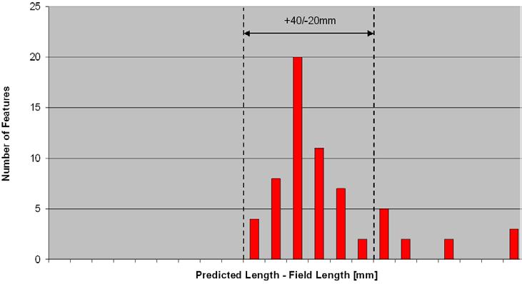
7 8 Case Study 1 GE s Phased Array tool inspected three 26 lines in North America with a total length of 1086 km in the DUO mode (simultaneous crack detection and wall thickness measurement). The inspected pipelines transport diesel, which was also used as coupling medium during the runs. The only relevant defect type detected was SCC. 8.1 Defect Classification All 76 feature verifications confirmed the classification from the report. There were no false digs. This totally complies with the 90% POI statement of the tool specification. 8.2 Crack Sizing For SCC, the maximum depth, the length of the crack field and the length of the largest interlinked crack are reported for each crack field. In order to obtain optimum defect sizing, the first dig results were used to finalize the sizing algorithms. As Fig. 8 & 9 show, 64 of 76 reported depths were within the ±1mm band indicated by the red lines and 41 of 53 verified lengths of interlinked cracks were within the +40/-20 mm range indicated by the black dashed lines. This means, that the depths measurement of the inline inspection complies with the 90% certainty statement (with 95% confidence, according to API 1163) of the tool specification. The certainty of the length measurement seems to be near to 90% - for the clarification of this case, the interaction rules applied in field and with the ILI data need to be considered. It must be noted that the current method for reporting the depth of features with the conventional ultrasonic crack tools is to state a depth band, usually expressed as a percentage of wall thickness (e.g %, %, etc) with a tolerance added to that band. If the actual depth band plus tolerance range were plotted on the graph in Figure 8 for each corresponding feature, the area bounded by that tolerance would be much wider than the width of the red lines shown. Fig. 8: Unity plot predicted depth vs. field depth Fig. 9: Largest interlinked crack: deviation from field measurement


8 9 Case Study 2 GE s Phased Array tool inspected three 36 lines also in North America with a total length of 941 km in the crack detection mode. The pipelines transport gas. For the inspections, water or diesel batches were used for the coupling. In one of the lines an additional GE UltraScan CD crack detection tool was run simultaneously. 9.1 Defect Classification All 64 feature verifications confirmed the classification from the report. There were no false digs. This totally complies with the 90% POI statement of the tool specification. 9.2 Crack Sizing For SCC, the maximum depth, the length of the crack field and the length of the largest interlinked crack are reported for each crack field. In order to obtain optimum defect sizing, the first dig results were used to finalize the sizing algorithms. As Fig. 10 & 11 show, 53 of 64 reported depths were within the ±1mm band indicated by the red dashed lines and 52 of 64 lengths of interlinked cracks were within the +40/-20 mm black dashed lines. This means, that the depths measurement of the inline inspection complies with the 90% certainty statement (with 95% confidence, according to API 1163) of the tool specification. The certainty of the length measurement seems to be near to 90% - for the clarification of this case, the interaction rules applied in field and with the ILI data need to be considered. Fig. 10: Predicted depth vs. field depth Fig. 11: Largest interlinked crack: deviation from field measurement
9

10 9.3 Comparison Between UltraScan DUO and UltraScan CD Data The minimum defect size that the Phased Array tool can detect is specified with a length of 25 mm and a depth of 1 mm. The conventional UltraScan CD tool detects defects with a minimum length of 30 mm and a depth of 1 mm. From the 64 defects detected by the Phased Array tool, the conventional UltraScan CD tool detected 58. The other 6 were either between 25 mm and 30 mm or just above 1 mm depth. Also regarding sizing accuracy, the Phased Array tool performed better than the conventional tool. The tolerance for 90% certainty is ±1 mm for the Phased Array and ±1.2 mm for the UltraScan CD. Fig. 12: Depth sizing comparison between Phased Array tool and conventional tool 10 Summary and Way Forward The extensive analysis of the performance of the Phased Array technology on the UltraScan DUO inspection tool from these two case studies indicates that the Phased Array is the more accurate technology compared to the technology using single crystal oscillator (piezo) transducers. The Phased Array provides more flexibility than the single crystal oscillator transducer which has a fixed angle and focal length. Phased Array allows a flexible adaptation of the ultrasonic sensor properties like sensor width, distance between sensors or shot angle - just by changing software parameters. This leads to improved results, especially on the defect detection and the depth sizing. The next step for the Phased Array technology is to take advantage of this flexibility in ways which bring even more value to the pipeline operator through enhanced sizing accuracy. Some projects underway in this area include pitch and catch studies, paint brush, and varying firing angles in the same inspection as a way to deliver the highest reflected signal amplitude. Further improvement of defect detection and depth sizing will also be subject of the next steps of improvement in crack detection: Besides shooting at a spot with only one angle, two different angles could be applied. Instead of one sensor shooting and listening, one virtual sensor can shoot and another can listen. For inline inspection, Phased Array is the only reasonable technology for these advanced measurement methods.
Pipeline & Specialty Services (P&SS)
") Pipeline & Specialty Services (P&SS) A Pipeline Inspection Case Study: Design Improvements on a New Generation UT In-line Inspection Crack Tool Mark Slaughter Global Product Line Manager Pipeline & Specialty
Pipeline & Specialty Services (P&SS) A Pipeline Inspection Case Study: Design Improvements on a New Generation UT In-line Inspection Crack Tool Mark Slaughter Global Product Line Manager Pipeline & Specialty
Pipeline Technology Conference 2010
 THRESHOLDS, ACCURACIES AND RESOLUTION: QUANTITATIVE MEASUREMENT AND ITS ADVANTAGES FOR METAL LOSS INSPECTION A. Barbian, M. Beller, A. Hugger, C. Jäger, A. Pfanger NDT Systems & Services Stutensee, Germany
New Pig for Gas Pipeline Crack Inspections Enhancements Derived from 5 Years Operational Experience
 New Pig for Gas Pipeline Crack Inspections Enhancements Derived from 5 Years Operational Experience By David Allen, Andrew Mann, Stephan Tappert. GE Oil & Gas, PII Pipeline Solutions Abstract This paper
RELIABILITY OF GUIDED WAVE ULTRASONIC TESTING. Dr. Mark EVANS and Dr. Thomas VOGT Guided Ultrasonics Ltd. Nottingham, UK
 RELIABILITY OF GUIDED WAVE ULTRASONIC TESTING Dr. Mark EVANS and Dr. Thomas VOGT Guided Ultrasonics Ltd. Nottingham, UK The Guided wave testing method (GW) is increasingly being used worldwide to test
EMAT Application on Incoloy furnace Tubing Ramamohan Reddy M (ASNT Level III UT, PCN Level III UT,PAUT&TOFD)
") EMAT Application on Incoloy furnace Tubing By Ramamohan Reddy M (ASNT Level III UT, PCN Level III UT,PAUT&TOFD) Outlines 1. Introduction EMAT 2. EMAT- Ultrasound waves 3. EMAT-Surface waves 4. EMAT-Guided
EMAT Application on Incoloy furnace Tubing By Ramamohan Reddy M (ASNT Level III UT, PCN Level III UT,PAUT&TOFD) Outlines 1. Introduction EMAT 2. EMAT- Ultrasound waves 3. EMAT-Surface waves 4. EMAT-Guided
New Multi-Technology In-Line Inspection Tool For The Quantitative Wall Thickness Measurement Of Gas Pipelines
 New Multi-Technology In-Line Inspection Tool For The Quantitative Wall Thickness Measurement Of Gas Pipelines A. Barbian 1, M. Beller 1, F. Niese 2, N. Thielager 1, H. Willems 1 1 NDT Systems & Services
A PIPELINE INSPECTION CASE STUDY: DESIGN IMPROVEMENTS ON A NEW GENERATION UT IN-LINE INSPECTION CRACK TOOL
 A PIPELINE INSPECTION CASE STUDY: DESIGN IMPROVEMENTS ON A NEW GENERATION UT IN-LINE INSPECTION CRACK TOOL By: Mark Slaughter, Weatherford International, P&SS, USA Ing. Michael Huss, Adria Wien Pipeline
VERSATILE USAGE OF ELECTROMAGNETIC ACOUSTIC TECHNOLOGIES FOR IN-LINE INSPECTION OF AGEING PIPELINES
 VERSATILE USAGE OF ELECTROMAGNETIC ACOUSTIC TECHNOLOGIES FOR IN-LINE INSPECTION OF AGEING PIPELINES By: Dr.V.A.Kanaykin, Dr.B.V.Patramanskiy, Dr.V.E.Loskutov, Mr.V.V.Lopatin Spetsneftegaz NPO JSC - Russia
The Essentials of Pipeline Integrity Management
 TRAINING METHODOLOGY This interactive training workshop includes the following training methodologies : Lectures Video Discussion of case histories and hands on calculations WHO SHOULD ATTEND The course
18th World Conference on Non-destructive Testing, April 2012, Durban, South Africa
 18th World Conference on Non-destructive Testing, 16-20 April 20, Durban, South Africa Guided Wave Testing for touch point corrosion David ALLEYNE Guided Ultrasonics Ltd, London, UK; Phone: +44 2082329102;
DACON INSPECTION SERVICES I MFL INSPECTION OF PIPELINES
 I MFL INSPECTION OF PIPELINES DACON AND INLINE INSPECTION Dacon well-known for pipeline inspection solutions using UT, MFL and LRUT UT tools provide unrivaled inspection accuracy compared to MFL Wide variety
Pipeline Research Council International, Inc.
 Pipeline Research Council International, Inc. Technology Development for Pipeline Integrity Current Features & Coming Attractions API 2012 Pipeline Conference & Cybernetics Symposium Phoenix, AZ April
Heat Exchanger & Boiler Tube Inspection Techniques
 Overview For the in-service inspection of ferromagnetic, non-ferromagnetic and fin-fan tubes, the following advanced techniques offer high defect detection capabilities and accurate defect analysis: Multiple
RapidScan II Application Note General Composite Scanning
 RapidScan II Application Note General Composite Scanning RapidScan II General Composite Scanning Application Note Page 1 Applications The RapidScan system has been utilised for a wide range of inspections
Subsea Integrity and Efficiency Conference
 SUBSEA INTEGRITY & EFFICIENCY CONFERENCE 2015 Subsea Integrity and Efficiency Conference - 2015 Flexible Riser Integrity Assessment with Advanced MEC-FIT Technique Andreas Boenisch a.boenisch@innospection.com
Testing of Buried Pipelines Using Guided Waves
 Testing of Buried Pipelines Using Guided Waves A. Demma, D. Alleyne, B. Pavlakovic Guided Ultrasonics Ltd 16 Doverbeck Close Ravenshead Nottingham NG15 9ER Introduction The inspection requirements of pipes
Quantitative Short Range Guided Wave System
 Quantitative Short Range Guided Wave System Jimmy Fong 1, and Tomasz Pialucha Guided Ultrasonics Ltd., Wavemaker House, The Ham, Brentford, TW8 8HQ, United Kingdom More info about this article: http://www.ndt.net/?id=22108
DACON INSPECTION SERVICES. Phased Array Ultrasonic Testing
 Phased Array Ultrasonic Testing Who we are Conventional and Advanced NDT and Inspection Services Oil and Gas, Refinery, Petrochemical, Heavy Industry, Mining Over 400 personnel including more than 300
Easy Ultrasonic Phased Array Inspection of Corrosion - Resistant Alloys and Dissimilar Weld Materials
 Multimedia Application Notes Easy Ultrasonic Phased Array Inspection of Corrosion - Resistant Alloys and Dissimilar Weld Materials Many industries increasingly use austenitic welds and welds containing
Application of SLOFEC and Laser Technology for Testing of Buried Pipes
 19 th World Conference on Non-Destructive Testing 2016 Application of SLOFEC and Laser Technology for Testing of Buried Pipes Gerhard SCHEER 1 1 TMT - Test Maschinen Technik GmbH, Schwarmstedt, Germany
PRACTICAL ENHANCEMENTS ACHIEVABLE IN LONG RANGE ULTRASONIC TESTING BY EXPLOITING THE PROPERTIES OF GUIDED WAVES
 PRACTICAL ENHANCEMENTS ACHIEVABLE IN LONG RANGE ULTRASONIC TESTING BY EXPLOITING THE PROPERTIES OF GUIDED WAVES PJ Mudge Plant Integrity Limited, Cambridge, United Kingdom Abstract: Initial implementations
Pipeline Inspection Technologies Demonstration Report Final
 University of Nebraska - Lincoln DigitalCommons@University of Nebraska - Lincoln United States Department of Transportation -- Publications & Papers U.S. Department of Transportation 26 Pipeline Inspection
FLOORMAP3Di MFL Floor Scanner with STARS Top & Bottom Defect Discrimination & MFLi Advanced Defect Analysis
 MFL Floor Scanner with STARS Top & Bottom Defect Discrimination & MFLi Advanced Defect Analysis > COMPLETE TANK FLOOR MAPPING > ENHANCED PROBABILITY OF DETECTION TANKS PIPES VESSELS > HIGH RESOLUTION SCANNING
Application of Ultrasonic Guided Wave to Heat Exchanger Tubes Inspection
 17th World Conference on Nondestructive Testing, 25-28 Oct 2008, Shanghai, China Application of Ultrasonic Guided Wave to Heat Exchanger Tubes Inspection Ik-Keun PARK 1,a, Yong-Kwon KIM 2,b, Sae-Jun PARK
PAUT as Tool for Corrosion Damage Monitoring
 More info about this article: http://www.ndt.net/?id=21146 ShivputraRamanna Tangadi 1, N.K.S. Praveen Telidevara 1, Hari Kishore Maddi 1 1 Sievert India Pvt. Ltd. (A Bureau Veritas Company), 16 & 17, Sec-2,
DEFECT SIZING IN PIPE USING AN ULTRASONIC GUIDED WAVE FOCUSING TECHNIQUE
 DEFECT SIZING IN PIPE USING AN ULTRASONIC GUIDED WAVE FOCUSING TECHNIQUE Jing Mu 1, Li Zhang 1, Joseph L. Rose 1 and Jack Spanner 1 Department of Engineering Science and Mechanics, The Pennsylvania State
In service application of EMAT in Boiler Water Wall Tubes and High Temperature Components
 More Info at Open Access Database www.ndt.net/?id=18662 In service application of EMAT in Boiler Water Wall Tubes and High Temperature Components R Dhanasekaran 1, Lopez Borja 2, Mukesh Arora 1 1 NDTS
Ring Pair Corrosion Monitor : RPCM
 Ring Pair Corrosion Monitor : RPCM RPCM is an in-line, piggable, monitor for pipelines, flow lines and process pipework giving true corrosion rate measurement in all service conditions due to full inner
Penn State University ESM Ultrasonics R&D Laboratory Joseph L. Rose Research Activities
 Penn State University ESM Ultrasonics R&D Laboratory Joseph L. Rose Research Activities Crack Detection in Green Compacts The Center for Innovative Sintered Products Identifying cracked green parts before
High-Resolution Corrosion Monitoring for Reliable Assessment of Infrastructure
 19 th World Conference on Non-Destructive Testing 2016 High-Resolution Corrosion Monitoring for Reliable Assessment of Infrastructure André Lamarre 1 1 Olympus Scientific Solutions Americas, Quebec City,
Long Range Ultrasonic Testing - Case Studies
 More info about this article: http://www.ndt.net/?id=21145 Prawin Kumar Sharan 1, Sheethal S 1, Sri Krishna Chaitanya 1, Hari Kishore Maddi 1 1 Sievert India Pvt. Ltd. (A Bureau Veritas Company), 16 &
Ripple and Uniformity Measurement of a Phased-Array Testing-Machine for round-bar Testing
 17th World Conference on Nondestructive Testing, 25-28 Oct 2008, Shanghai, China Ripple and Uniformity Measurement of a Phased-Array Testing-Machine for round-bar Testing Stephan FALTER 1, Josef MAIER
Simulation of Ultrasonic Testing of Rail Wheel Face using Phased Array and DDF technique
 Simulation of Ultrasonic Testing of Rail Wheel Face using Phased Array and DDF technique Anand Desai, Ph.D. Abstract This paper presents a method of increasing the near surface resolution of a rail wheel
SonaFlex. Set of Portable Multifunctional Equipment for Non-contact Ultrasonic Examination of Materials
 SonaFlex Set of Portable Multifunctional Equipment for Non-contact Ultrasonic Examination of Materials General Overview of the Testing Equipment SonaFlex is a unique intelligent ultrasonic testing system
Ultrasonic sensors in subsea oil & gas production current use and opportunities
 Ultrasonic sensors in subsea oil & gas production current use and opportunities By Bjørn Stevning Hole Senior Product Engineer, TechnipFMC 5/31/2018 Page footer text 1 What is ultrasound and how can ultrasound
Structural Integrity Monitoring using Guided Ultrasonic Waves
 Structural Integrity Monitoring using Guided Ultrasonic Waves Paul Fromme Department of Mechanical Engineering University College London NPL - May 2010 Structural Integrity Monitoring using Guided Ultrasonic
Phased Array UT Application For Boiler Tube Inspection in Manufacturing And In-Service Anandamurugan S 1, Siva Sankar Y 2
 More Info at Open Access Database www.ndt.net/?id=15156 Phased Array UT Application For Boiler Tube Inspection in Manufacturing And In-Service Anandamurugan S 1, Siva Sankar Y 2 1 GE Inspection Technologies,
Generation Laser Scanning Method for Visualizing Ultrasonic Waves Propagating on a 3-D Object
 1st International Symposium on Laser Ultrasonics: Science, Technology and Applications July 16-18 2008, Montreal, Canada Generation Laser Scanning Method for Visualizing Ultrasonic Waves Propagating on
TOOLS, VENDORS, SERVICES - A REVIEW OF CURRENT IN-LINE INSPECTION TECHNOLOGIES
 TOOLS, VENDORS, SERVICES - A REVIEW OF CURRENT IN-LINE INSPECTION TECHNOLOGIES By M. Beller, K. Reber, U. Schneider NDT Systems & Services AG ABSTRACT The paper provides an overview of the inline inspection
DEVELOPMENT OF ULTRASONIC WAVE NONDESTRUCTIVE INSPECTION ROBOT WITHOUT COUPLING MEDIUM USING EMAT
 DEVELOPMET OF ULTRAOIC WAVE ODETRUCTIVE IPECTIO ROBOT WITHOUT COUPLIG MEDIUM UIG EMAT R. Murayama,. Makiyama, Y. Aratani and Y. Taniguchi Fukuoka Institute of technology, Japan Abstract: The ultrasonic
Corrosion detection under pipe supports using EMAT Medium Range Guided Waves
 19 th World Conference on Non-Destructive Testing 2016 Corrosion detection under pipe supports using EMAT Medium Range Guided Waves Victor GARCIA 1, Carlos BOYERO 1, Jesus Antonio JIMENEZ GARRIDO 1 1 Innerspec
Detecting Stress Corrosion Cracking with Eddy Current Array Technology Cracking
 Detecting Stress Corrosion Cracking with Eddy Current Array Technology Cracking Emilie Peloquin, : emilie.peloquin@olympus ossa.com Advanced Technical Support Team Lead Americas Olympus Scientific Solutions
An Overview Algorithm to Minimise Side Lobes for 2D Circular Phased Array
 An Overview Algorithm to Minimise Side Lobes for 2D Circular Phased Array S. Mondal London South Bank University; School of Engineering 103 Borough Road, London SE1 0AA More info about this article: http://www.ndt.net/?id=19093
Ultrasonic Guided Wave Applications
 Ultrasonic Guided Wave Applications Joseph L. Rose Penn State University April 29-30, 2013 2013 Center for Acoustics and Vibrations meeting What is a Guided Wave? (Guided wave requires boundary for propagation
REDUCING DEEPWATER PIPELINE INSPECTION COSTS
 REDUCING DEEPWATER PIPELINE INSPECTION COSTS WHITE PAPER INTRODUCTION Inspecting a deepwater pipeline is extremely challenging. One problem might be that it lies more than 2,000 m (6,500 ft.) subsea, giving
Visual Testing of Pipe Threads
 From NDT Technician, Vol. 10, No. 1, pp: 1 5. Copyright 2011 The American Society for Nondestructive Testing, Inc. The American Society for Nondestructive Testing www.asnt.org FOCUS AAs an oil well is
A PHASED ARRAY ULTRASONIC TESTING OF A MANUAL THICK AUSTENITIC WELD FEEDBACK
 19 th World Conference on Non-Destructive Testing 2016 A PHASED ARRAY ULTRASONIC TESTING OF A MANUAL THICK AUSTENITIC WELD FEEDBACK Didier FLOTTÉ 1, Sylvie BITTENDIEBEL 1 1 Institut de Soudure, Yutz, France
Chapter 4 Results. 4.1 Pattern recognition algorithm performance
 94 Chapter 4 Results 4.1 Pattern recognition algorithm performance The results of analyzing PERES data using the pattern recognition algorithm described in Chapter 3 are presented here in Chapter 4 to
Array Eddy Current for Fatigue Crack Detection of Aircraft Skin Structures
 Array Eddy Current for Fatigue Crack Detection of Aircraft Skin Structures Eric Pelletier, Marc Grenier, Ahmad Chahbaz and Tommy Bourgelas Olympus NDT Canada, NDT Technology Development, 505, boul. du
FLEXURAL TORSIONAL GUIDED WAVE PIPE INSPECTION
 FLEXURAL TORSIONAL GUIDED WAVE PIPE INSPECTION Z. Sun 1, L. Zhang 2, and J.L. Rose 2 1 GE Global Research Center, Niskayuna, NY 1239, USA 2 212 Earth and Engineering Science building, The Pennsylvania
Non-destructive Inspection Technique for Assuring the High-end Quality of Our Pipe and Tube
 Technical Report NIPPON STEEL & SUMITOMO METAL TECHNICAL REPORT No. 107 FEBRUARY 2015 UDC 669. 14-46 : 620. 179. 1 Non-destructive Inspection Technique for Assuring the High-end Quality of Our Pipe and
CIRCULAR LAMB AND LINEAR SHEAR HORIZONTAL GUIDED WAVE ARRAYS FOR STRUCTURAL HEALTH MONITORING
 CIRCULAR LAMB AND LINEAR SHEAR HORIZONTAL GUIDED WAVE ARRAYS FOR STRUCTURAL HEALTH MONITORING Thomas R. Hay, Jason Van Velsor, Joseph L. Rose The Pennsylvania State University Engineering Science and Mechanics
Welding Inspection Non-Destructive Testing Course Reference WIS 5
 Welding Inspection Non-Destructive Testing Course Reference WIS 5 Non Destructive Testing A welding inspector should have a working knowledge of NDT methods and their applications, advantages and disadvantages.
Isolation Scanner. Advanced evaluation of wellbore integrity
 Isolation Scanner Advanced evaluation of wellbore integrity Isolation Scanner* cement evaluation service integrates the conventional pulse-echo technique with flexural wave propagation to fully characterize
Improved Inspection of CRA-Clad Pipeline Girth Welds with the Use of Accessible Advanced Ultrasonic Phased-Array Technology
 Improved Inspection of CRA-Clad Pipeline Girth Welds with the Use of Accessible Advanced Ultrasonic Phased-Array Technology André Lamarre, Olympus Scientific Solutions Americas 11th European Conference
In-Line EMAT Ultrasonic Weld Inspection for ERW Tube Mill Using Guided Ultrasonic Waves
 In-Line EMAT Ultrasonic Weld Inspection for ERW Tube Mill Using Guided Ultrasonic Waves Jeffrey S. Monks Innerspec Technologies, Inc. 4004 Murray Place Lynchburg, VA 24501 Phone- 434-948-1306 Fax-434-948-1313
Standard Guide for Evaluating Performance Characteristics of Phased-Array Ultrasonic Testing Instruments and Systems 1
 Designation: E2491 08 Standard Guide for Evaluating Performance Characteristics of Phased-Array Ultrasonic Testing Instruments and Systems 1 This standard is issued under the fixed designation E2491; the
Optimized Semi-Flexible Matrix Array Probes for Large Rotor Shafts and DGS Sizing Diagram Simulation Tool
 19 th World Conference on Non-Destructive Testing 2016 Optimized Semi-Flexible Matrix Array Probes for Large Rotor Shafts and DGS Sizing Diagram Simulation Tool Dany DEVOS 1, Guy MAES 1, Patrick TREMBLAY
Inspection of pipe networks containing bends using long range guided waves
 Inspection of pipe networks containing bends using long range guided waves Ruth Sanderson TWI Ltd. Granta Park, Great Abington, Cambridge, CB21 6AL, UK 1223 899 ruth.sanderson@twi.co.uk Abstract Guided
CLAMP-ON ULTRASONIC FLOW METER APPLICATION AND PERFORMANCE WILLIAM E. FRASIER RETIRED CASEY HODGES CEESI MEASUREMENT SOLUTIONS
 CLAMP-ON ULTRASONIC FLOW METER APPLICATION AND PERFORMANCE WILLIAM E. FRASIER RETIRED CASEY HODGES CEESI MEASUREMENT SOLUTIONS JOE NETTLETON RT TECHNICALSOLUTIONS This paper is directed to ultrasonic natural
Sonotron NDT 4, Pekeris str., Rabin Science Park, Rehovot, 76702, Israel Phone:++972-(0) Fax:++972-(0)
 Fax:++972-(0)") ISONIC 2010 Portable Ultrasonic Phased Array Flaw Detector and Recorder Phased Array 32:32 phased array electronics independently adjustable emitting and receiving aperture, parallel firing, A/D conversion,
ISONIC 2010 Portable Ultrasonic Phased Array Flaw Detector and Recorder Phased Array 32:32 phased array electronics independently adjustable emitting and receiving aperture, parallel firing, A/D conversion,
New generation of welding and inspection systems
 New generation of welding and inspection systems Throughout the pipeline industry, and particularly in offshore and spool base production, welding requirements are shifting toward higher quality, greater
GUIDELINES FOR THE APPLICATION OF TIME-OF-FLIGHT DIFFRACTION (TOFD) AND PHASED ARRAY ULTRASONIC TESTING (PAUT) TECHNIQUES
 AND PHASED ARRAY ULTRASONIC TESTING (PAUT) TECHNIQUES") GUIDANCE NOTES GD02-2017 CHINA CLASSIFICATION SOCIETY GUIDELINES FOR THE APPLICATION OF TIME-OF-FLIGHT DIFFRACTION (TOFD) AND PHASED ARRAY ULTRASONIC TESTING (PAUT) TECHNIQUES 2017 Effective from February
GUIDANCE NOTES GD02-2017 CHINA CLASSIFICATION SOCIETY GUIDELINES FOR THE APPLICATION OF TIME-OF-FLIGHT DIFFRACTION (TOFD) AND PHASED ARRAY ULTRASONIC TESTING (PAUT) TECHNIQUES 2017 Effective from February
ISO INTERNATIONAL STANDARD. Non-destructive testing of welds Radiographic testing Part 1: X- and gamma-ray techniques with film
 INTERNATIONAL STANDARD ISO 17636-1 First edition 2013-01-15 Non-destructive testing of welds Radiographic testing Part 1: X- and gamma-ray techniques with film Contrôle non destructif des assemblages soudés
Developments in Ultrasonic Phased Array Inspection I
 Developments in Ultrasonic Phased Array Inspection I A Detailed Study of Inspecting Thick Parts Using Large Aperture Phased Arrays and DDF D. Braconnier, S. Okuda, G. Dao, KJTD co. Ltd, Japan ABSTRACT
Basic Measurements for Pipe Inspections
 Basic Measurements for Pipe Inspections Period 7 Basic Corrosion Course 2017 February 21-23, 2017 Mark Anderson-MTS 1 DOT 192.459 External corrosion control: Examination of buried pipeline when exposed.
Sensorlink Corrosion monitoring on welds. Subsea Controls Down Under ISO 9001:2008 certified IECEx certified
 Sensorlink Corrosion monitoring on welds Subsea Controls Down Under 2018 Jan-Tore Ervik, CMO Jan-tore.ervik@sensorlink.no ISO 9001:2008 certified IECEx certified 2 Outline Sensorlink Motivations and applications
Phased Array Inspection of Coarse Grain Welds (Austenitic, CRA, etc)
") Very high level of the structural noise makes regular shear wave ultrasonic inspection either conventional or PA practically inapplicable to the coarse grain welds. The solution may be found with use of
Very high level of the structural noise makes regular shear wave ultrasonic inspection either conventional or PA practically inapplicable to the coarse grain welds. The solution may be found with use of
S. GURESH 4 JAN 2017 S. JOHNSON 4 JAN 2017
 PAGE 2 OF 15 1.0 PURPOSE This Inspection Method describes the methodology for Ultrasonic Examination using manual and semi-automatic techniques by the contact and immersion longitudinal wave method and
Enhanced Resonant Inspection Using Component Weight Compensation. Richard W. Bono and Gail R. Stultz The Modal Shop, Inc. Cincinnati, OH 45241
 Enhanced Resonant Inspection Using Component Weight Compensation Richard W. Bono and Gail R. Stultz The Modal Shop, Inc. Cincinnati, OH 45241 ABSTRACT Resonant Inspection is commonly used for quality assurance
Aboveground Monitoring - Casings Long Range Electromagnetic Wave (EMW) Inspection
 Inspection") Aboveground Monitoring - Casings Long Range Electromagnetic Wave (EMW) Inspection Period 7 Pipeline Coatings Course 2017 February 21-23, 2017 John DeWees, CEO WaveTrue 2017 1 Electromagnetic Wave Inspection
Aboveground Monitoring - Casings Long Range Electromagnetic Wave (EMW) Inspection Period 7 Pipeline Coatings Course 2017 February 21-23, 2017 John DeWees, CEO WaveTrue 2017 1 Electromagnetic Wave Inspection
BINDT Telford. Guided Wave Testing and Monitoring Over Long and Short Ranges
 BINDT Telford Guided Wave Testing and Monitoring Over Long and Short Ranges David Alleyne, Tomasz Pialucha and Brian Pavlakovic 6 September 2017 Outline Background Guided Wave Testing (GWT) Concepts Wave
Using Critical Zone Inspection and Response Monitoring To Prove Riser Condition. M Cerkovnik -2H Offshore
 Using Critical Zone Inspection and Response Monitoring To Prove Riser Condition M Cerkovnik -2H Offshore Agenda 1. Introduction 2. High level methodology 3. Verifying condition 4. Defining requirements
THE USE OF MAGNETOSTRICTIVE EMAT TRANSDUCERS ON OXIDE SCALED BOILER TUBES
 THE USE OF MAGNETOSTRICTIVE EMAT TRANSDUCERS ON OXIDE SCALED BOILER TUBES K. Lee, T. Nelligan Panametrics-NDT, A business of R/D Tech Instruments, Inc., Waltham, Massachusetts, USA Abstract: The utilization
FLOORMAP3Di-R. Twice as Fast Uncompromised Quality
 FLOORMAP3Di-R High Speed MFL Floor Scanner with STARS Top & Bottom Defect Discrimination & MFLi Advanced Defect Analysis Twice as Fast Uncompromised Quality > COMPLETE TANK FLOOR MAPPING > ENHANCED PROBABILITY
JOHANN CATTY CETIM, 52 Avenue Félix Louat, Senlis Cedex, France. What is the effect of operating conditions on the result of the testing?
 ACOUSTIC EMISSION TESTING - DEFINING A NEW STANDARD OF ACOUSTIC EMISSION TESTING FOR PRESSURE VESSELS Part 2: Performance analysis of different configurations of real case testing and recommendations for
Inspection Approaches & Experience. for Inspecting Challenging Subsea Assets
 Subsea Malaysia 2015 Inspection Approaches & Experience for Inspecting Challenging Subsea Assets Jason Tong Regional Sales Engineer, Innospection j.tong@innospection.com Subsea Malaysia 2015 CONTENT -
Non-Intrusive Ultrasonic Corrosion-Rate Measurements in Lieu of Manual and Intrusive Methods
 Non-Intrusive Ultrasonic Corrosion-Rate Measurements in Lieu of Manual and Intrusive Methods Mark Feydo, Steve Strachan, Bruce Pellegrino Sensor Networks, Inc. 176-500 Technology Drive Boalsburg, PA, 16827,
The Battle of Carbon Steel
 More info ab The Battle of Carbon Steel Advantages of Eddy Current Array over Magnetic Particle and Penetrant Testing for Inspecting the Surface of Carbon Steel Welds Terence Burke Product Application
The Implementation of the New Standard EN ISO for Ultrasonic Phased-Array Systems at the Manufacturer
 19 th World Conference on Non-Destructive Testing 2016 The Implementation of the New Standard EN ISO 18563 for Ultrasonic Phased-Array Systems at the Manufacturer Johannes BUECHLER 1, Udo SCHLENGERMANN
ISO INTERNATIONAL STANDARD. Non-destructive testing Ultrasonic thickness measurement
 INTERNATIONAL STANDARD ISO 16809 First edition 2012-11-15 Non-destructive testing Ultrasonic thickness measurement Essais non destructifs Mesurage de l'épaisseur par ultrasons Reference number ISO 2012
Guided Wave Travel Time Tomography for Bends
 18 th World Conference on Non destructive Testing, 16-20 April 2012, Durban, South Africa Guided Wave Travel Time Tomography for Bends Arno VOLKER 1 and Tim van ZON 1 1 TNO, Stieltjes weg 1, 2600 AD, Delft,
ClampOn, Inc. Ultrasonic Intelligent Sensors. Presented by Hans A. Wagner
 ClampOn, Inc. Ultrasonic Intelligent Sensors Presented by Hans A. Wagner Bergen, Norway Locations Project Management Engineering and Manufacturing Research and Development Sales and Service for Eastern
CRACKS DETECTION ON METAL PARTS BY ACOUSTIC EMISSION
 DELALANDE Christophe RENCKERT Olivier ZARIFE Victor CRACKS DETECTION ON METAL PARTS BY ACOUSTIC EMISSION 303 Abstract Control by acoustic emission during fitting of a bush in a metal part has been selected
CLAMP-ON ULTRASONIC FLOW METER APPLICATION AND PERFORMANCE. William E. Frasier (CMSI: Retired) & Joseph H. Nettleton
 & Joseph H. Nettleton") CLAMP-ON ULTRASONIC FLOW METER APPLICATION AND PERFORMANCE William E. Frasier (CMSI: Retired) & Joseph H. Nettleton R T Technical Solutions 4484 Hodgson Rd Nederland, TX 77627 This paper is directed to
CLAMP-ON ULTRASONIC FLOW METER APPLICATION AND PERFORMANCE William E. Frasier (CMSI: Retired) & Joseph H. Nettleton R T Technical Solutions 4484 Hodgson Rd Nederland, TX 77627 This paper is directed to
INSPECTION OF THERMAL BARRIERS OF PRIMARY PUMPS WITH PHASED ARRAY PROBE AND PIEZOCOMPOSITE TECHNOLOGY
 INSPECTION OF THERMAL BARRIERS OF PRIMARY PUMPS WITH PHASED ARRAY PROBE AND PIEZOCOMPOSITE TECHNOLOGY J. Poguet Imasonic S.A. France E. Abittan EDF-GDL France Abstract In order to meet the requirements
ADAPTIVE CORRECTION FOR ACOUSTIC IMAGING IN DIFFICULT MATERIALS
 ADAPTIVE CORRECTION FOR ACOUSTIC IMAGING IN DIFFICULT MATERIALS I. J. Collison, S. D. Sharples, M. Clark and M. G. Somekh Applied Optics, Electrical and Electronic Engineering, University of Nottingham,
A discussion of Laser Beam Profiling and the subject of Accuracy
 A discussion of Laser Beam Profiling and the subject of Accuracy Question: How can I be certain that my Beam Profiler is measuring accurately? Is there a standard calibration methodology? Answer: There
Latest Developments for Pipeline Girth Welds using 3D Imaging Techniques. Novel Construction Meeting Jan van der Ent March 2016, Geneva
 Latest Developments for Pipeline Girth Welds using 3D Imaging Techniques Novel Construction Meeting Jan van der Ent March 2016, Geneva 1 Content of presentation Standard A(UT) inspection What do we expect
DIFFICULT TO PIG AND TO INSPECT OFFSHORE PIPES
 DIFFICULT TO PIG AND TO INSPECT OFFSHORE PIPES K. Reber, Innospection Germany GmbH, Stutensee, Germany S. Hartmann, Innospection Ltd., UK A. Boenisch, Innospection Ltd., UK Introduction When it comes to
Pipeline Girth Weld Inspections using Ultrasonic Phased Arrays Michael Moles, Noël Dubé, Simon Labbé and Ed Ginzel
 Pipeline Girth Weld Inspections using Ultrasonic Phased Arrays Michael Moles, Noël Dubé, Simon Labbé and Ed Ginzel Abstract: Automated ultrasonics (AUT) is more reliable, faster, has better detection of
Hiding In Plain Sight. How Ultrasonics Can Help You Find the Smallest Bonded Wafer and Device Defects. A Sonix White Paper
 Hiding In Plain Sight How Ultrasonics Can Help You Find the Smallest Bonded Wafer and Device Defects A Sonix White Paper If You Can See It, You Can Solve It: Understanding Ultrasonic Inspection of Bonded
The Development of Laser Ultrasonic Visualization Equipment and its Application in Nondestructive Inspection
 17th World Conference on Nondestructive Testing, 25-28 Oct 2008, Shanghai, China The Development of Laser Ultrasonic Visualization Equipment and its Application in Nondestructive Inspection Bo WANG 1,
Pipeline Research Council International, Inc.
 Pipeline Research Council International, Inc. Integrity Assessment of Difficult to Inspect Pipelines Evaluating Select Areas Using High Resolution NDE Hans Deeb Program Manager, Integrity & Inspection
Automated Ultrasonic Inspection for Pipeline Girth Welds
 Automated Ultrasonic Inspection for Pipeline Girth Welds Sebastien Rigault PipeWizard - Product Mgr. Bob Peck EMEA NDT Business Development Mgr. Pipeline Girth Weld Inspection: In the last several years
Module 4 Design for Assembly IIT BOMBAY
 Module 4 Design for Assembly Lecture 8 Case Studies - IV Instructional objectives The objective of this lecture is to exhibit how real components are designed in industry following some of the principles
Detection of Protective Coating Disbonds in Pipe Using Circumferential Guided Waves
 17th World Conference on Nondestructive Testing, 25-28 Oct 2008, Shanghai, China Detection of Protective Coating Disbonds in Pipe Using Circumferential Guided Waves Jason K. Van Velsor Pennsylvania State
ISO INTERNATIONAL STANDARD. Non-destructive testing of welds Radiographic testing of fusionwelded
 INTERNATIONAL STANDARD ISO 17636 First edition 2003-09-15 Non-destructive testing of welds Radiographic testing of fusionwelded joints Contrôle non destructif des assemblages soudés Contrôle par radiographie
ULTRASONIC QUALIFICATION CARD GUIDANCE INSTRUCTIONS
 ANDE OJT/TE/SELECTION FORM : Selected for Mark appropriate box below as applicable: On-The-Job Training (OJT) Task erformance Evaluation (TE) ID Number: NOTES: I have received adequate experience and can
A SHEAR WAVE TRANSDUCER ARRAY FOR REAL-TIME IMAGING. R.L. Baer and G.S. Kino. Edward L. Ginzton Laboratory Stanford University Stanford, CA 94305
 A SHEAR WAVE TRANSDUCER ARRAY FOR REAL-TIME IMAGING R.L. Baer and G.S. Kino Edward L. Ginzton Laboratory Stanford University Stanford, CA 94305 INTRODUCTION In this paper we describe a contacting shear