TROUBLESHOOTING. KSIO MINI Split DC Inverter Air Conditioner. Model Numbers:
|
|
|
- David Ray
- 6 years ago
- Views:
Transcription
1 KSIO MINI Split DC Inverter Air Conditioner TROUBLESHOOTING Model Numbers: KSIO009-H24-I KSIO02-H23-I KSIO08-H22-I KSIO024-H29-I KWIO09-H2 KWIO2-H2 WARNING Installation MUST conform with local building codes or, in the absence of local codes, with the National Electrical Code NFPA70/ANSI C-993, or current edition and Canadian Electrical Code Part CSA C.22.. The information contained in this manual is intended for use by a qualified service technician familiar with safety procedures and equipped with the proper tools and test instruments. Installation or repairs made by unqualified persons can result in hazards to you and others. Failure to carefully read and follow all instructions in this manual can result in equipment malfunction, property damage, personal injury and/or death. This service manual is to be used only by a certified service technician.
 For other models, please connect discharge resistance (approx.")
2 9. Troubleshooting Safety Electric charge is still kept in capacitors even when the power supply is shut off. Do not forget to discharge the electric charge in capacitor. Electrolytic Capacitors (HIGH VOLTAGE! - CAUTION!) For other models, please connect discharge resistance (approx. 00Ω 40W) or soldering iron (plug) between, - terminals of the electrolytic capacitor on the contrary side of the outdoor PCB. te: The picture above is only for reference. The plug of your side may be different. 38
3 9. Indoor Unit Error Display Operation lamp Timer lamp Display LED STATUS time X E0 Indoor unit EEPROM parameter error 2 times X E Indoor / outdoor units communication error 3 times X E2 Zero-crossing signal detection error 4 times X E3 Indoor fan speed has been out of control 5 times X E4 6 times X E5 Indoor room temperature sensor T open circuit or short circuit Evaporator coil temperature sensor T2 open circuit or short circuit 7 times X EC Refrigerant leakage detection 2 times O F 3 times O F2 4 times O F3 Outdoor ambient temperature sensor T4 open circuit or short circuit Condenser coil temperature sensor T3 open circuit or short circuit Compressor discharge temperature sensor T5 open circuit or short circuit 5 times O F4 Outdoor unit EEPROM parameter error 6 times O F5 Outdoor fan speed has been out of control times P0 IPM malfunction or IGBT over-strong current protection 2 times P Over voltage or over low voltage protection 3 times P2 High temperature protection of compressor top diagnosis and solution(only for 9k,2k models) 5 times P4 Inverter compressor drive error Olight Xoff flash 39
4 9.2 Outdoor unit error display For KSIO009-H24-I, KSIO02-H23-I: 40
5 . Problems LED 2 (Green) LED (Red) IU display Standby for normal O X 2 Operation normally X O 3 IPM malfunction or IGBT over-strong current protection X P0 4 Over voltage or too low voltage protection O O P 5 Over voltage or too low voltage protection O P 6 Inverter compressor drive error X P4 7 Inverter compressor drive error O P4 8 Inverter compressor drive error P4 4
6 KSIO08-H22-O T3.5AL/250VAC CN3 E2 FUSE2 T20AL/250VAC PTC PTC2 HEAT-N RY4 CN4 HEAT-L RY2 RY3 BLUE 4-WAY-N CN33 4-WAY-N L-OUT ZR2 R55 RY CN3 C64 E5 FUSE E3 CN32 E4 CN8 CN9 CN7 CN6 C3 L-IN CN2 ZR3 CN37 CN4 CompTop PMV CN2 C5 D7 CN30 R38 BROWN C2 R95 HuiQi L R8 T C N-IN CN R83 R9 CN3 CN20 C8 R47 DAS CN38 R82 D9 E25 R37 Q R40 E4 R30 R3 R43 IC8 R9 R2 R45 ZR Q2 IC0 R56 C22 IC C24 D4 E23 PaiQi D R4 CN S DZ R20 R60 R44 IC203 CN6 R208 C26 R207 IC202 R23 IC9 C23 C208 E7 E204 R48 R22 R46 TEMP IC7 R204 R42 R5 R209 R2 D206 C23 C53 R54 R203 Q3 R39 R62 CN5 C6 C C24 C205 C206 C202 C204 R6 R27 IC20 R205 R20 E8 R50 R49 C9 E24 D2 D203 D202 E202 R202 IC3 C52 E20 C29 C38 T20 C49 R59 C36 C4 E 6 7 R70 R53 C3 R7 R20 C20 C209 R69 IC5 D204 R79 R76 R67 D205 D0 C68 R206 D20 R26 C203 R68 R80 C72 CN34 C2 R74 C62 YELLOW D209 E203 C45 X C42 C4 IC8 C7 CN36 D207 E207 E3 IC4 R94 C63 D208 R25 R24 LED3 C73 R92 R93 C20 C4 C47 IC6 LED4 C69 R64 R90 R89 E28 R65 R77 C56 LED2 LED E206 R27 IC3 R28 CN22 R29 C60 C6 TestPort CN2 PCPort CN24 IC9 C20 C30 CE-KFR26W/BP3N(PMV)-20.D.3.WP2-24LC04 IC7 OSC R63 R66 R73 R75 R78 R R2 24LC256 C37 C40 C39 RED CN25 IC5 C50 E6 R57 C5 R36 E8 C58 R52 DZ2 IC6 C2 R35 R34 IC2 C8 E5 C25 C28 C59 CN26 R33 C7 E27 BR2 R32 C65 C27 C66 R04 E26 D6 D7 D5 R0 R87 C54 R84 C55 R02 R0 R09 R07 R08 R06 R58 R72 C44 C43 C48 C70 R86 CN7 U CN8 E2 V E20 CN9 W R03 R05 R9 C57 R D R8 E22 C67 C33 C46 E9 C35 RED CN28 BLUE BROWN CN29 C34 R88 R85 C32 CN27 YELLOW IPM U V W N BR CN35 VB VB2 VB3 P U V W U- V- W- FAULT ISO 7V VSS LED2 LED2 on and LED off (standby) LED2 off and LED on (running) LED other status (error) LED4 LED3 power light when power is on, LED4 aways on Flashing once per second(low speed flashing) (standby) Flashing once per half second (high speed flashing) (error) aways on (running). Problems LED2 (Green) LED (Red) IU display standby for normal O X 2 Operation normally X O 3 IPM malfunction or IGBT over-strong current protection X P0 4 Over voltage or too low voltage protection O O P 5 Over voltage or too low voltage protection O P 6 Inverter compressor drive error X P4 7 Inverter compressor drive error O P4 8 Inverter compressor drive error P4 Olight Xoff 2.5Hz flash 42
7 43 KSIO024-H29-O P E Q L-OUT CE-KFR80W/BP3T4N(DC MOTOR)-30.D.03.WP- DC MOTOR 7V N- N- S P RUN LED (standby) Flashing once per second(low speed flashing) (error) Flashing once per half second (high speed flashing) (running) aways on P P2 FUSE T5A 250VAC D34 D33 D32 D3 CN28 Q5 CN5 N Q CN39 C83 C82 C8 C80 CN37 R8 R7 R6 R5 R4 R3 R2 R R98 L30 IC32 IC30 IC8 E33 E3 E28 E27 DZ D30 CN38 SW CN5 T2B CN27 PFC-CONTROL CN26 TestPort R0 R09 R08 R07 R06 R05 R04 R03 R97 R57 R56 R55 IC9 D28 D27 C79 C78 R77 DSP R46 E7 E8 E C77 C76 C75 C74 C73 C72 D C7 IC R87 IC5 D2 ZR3 ZR2 ZR RY4 RY3 RY2 RY R02 R0 R00 R99 R96 R95 R94 R93 R92 R9 R90 R89 R88 R86 R85 R84 R83 R82 R8 R80 R79 R78 R76 R75 R74 R73 R72 R7 R70 R69 R68 R67 R66 R65 R64 R63 R62 R6 R60 R59 R58 R54 R53 R52 R5 R50 R49 R48 R47 R45 R44 R42 R4 R40 R39 R38 R37 R36 R35 R34 R33 R32 R3 R30 R29 R28 R27 R26 R25 R24 R23 R22 R2 R20 R9 R8 R7 R6 R5 R4 R3 R R0 R9 R8 R7 R6 R5 R4 R3 R2 R Q4 Q3 Q2 PTC P- GND IC6 IC4 IC3 IC2 IC IC0 IC8 IC7 IC5 IC4 IC3 IC2 FUSE2 T30A 250VAC E3 E2 E0 E9 E6 E4 E2 E D9 D8 D7 D6 D4 D3 D2 D D0 D9 D8 D7 D6 D5 D4 D3 CT CONdebug CN25 S-A CN24 D CN23 S-B CN22 C CN2 TO-DRIVE CN20 S-C CN9 B CN8 A CN7 T3/T4 CN6 S-D CN4 LOW/HIGH CN2 CompTop CN7 PAI QI C59 C58 C57 C56 C55 C54 C53 C5 C49 C47 C46 C45 C44 C43 C42 C4 C40 C39 C38 C37 C36 C35 C34 C33 C32 C3 C30 C29 C28 C27 C26 C25 C24 C23 C22 C2 C20 C9 C8 C7 C6 C5 C4 C3 C2 C0 C9 C AS D20 D5 C60 C6 C62 C63 C64 C65 C66 C67 C68 C69 C70 E4 E5 IC6 X IC7 C8 C7 C6 L L2 CN2 N CN8 N CN 4-WAY CN6 HEAT CN9 HEAT2 CN3 L-IN CN4 N-IN CN29 N-OUT CN0 R20 LED C52 C48 C5 C3 C4 C2 C84 C C85 P-2 GND


8 9.3 Diagnosis and Solution 9.3. EEPROM parameter error diagnosis and solution (E0/F4) Error Code E0/F4 Malfunction decision conditions Indoor or outdoor PCB main chip does not receive feedback from EEPROM chip. Supposed causes Installation mistake Trouble shooting: Shut off the power supply and turn it on 5 seconds later. Is it still displaying the error code? PCB faulty If the EEPROM chip is welded on main PCB, replace the main PCB directly. Otherwise, check whether the EEPROM chip plugged in main PCB well? Correct the connection. Replace the main PCB. EEPROM: a read-only memory whose contents can be erased and reprogrammed using a pulsed voltage. For the location of EEPROM chip, please refer to the below photos. Indoor PCB Outdoor PCB (8k model) te: The two photos above are for reference only; it may be not the same with the ones on your side. 44
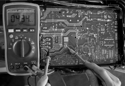
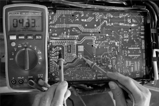
9 9.3.2 Indoor / outdoor unit s communication diagnosis and solution (E) Error Code E Malfunction decision conditions Supposed causes Wiring mistake Trouble shooting: Indoor unit does not receive the feedback from outdoor unit during 0 seconds and this condition happens four times continuously. Power off, then turn on the unit 5 seconds later(reconnect the power wire ).Is the error still displaying after several minutes? Indoor or outdoor PCB faulty Measure Vs, is it moving alternately with positive value? (Vs is the voltage between L2 and S of outdoor unit. Connect the red pin of multimeter with L2 port, black pin with S port) Check all the wiring with outdoor units. Is the wiring to the outdoor main PCB connect ed correctly? Is the reactor connected well? Measure the resistance of the reactor(the one without capacitor ). If it is zero,follow the below step. If not, replace a new reactor. Check all the wiring with indoor units. Is the wiring to the indoor main PCB connected correctly? Replace the outdoor main PCB. Replace the indoor main PCB. Power on. Is the error extinguished? Power on. Is the error extinguished? Replace the indoor main PCB. Replace the outdoor main PCB. 45


10 Remark: Use a multi-meter to test the DC voltage between L2 port and S port of outdoor unit. The red pin of multi-meter connects with L2 port while the black pin is for S port. When AC is running normal, the voltage will move alternately between -50V to 50V. If the outdoor unit is malfunctioning, the voltage will move alternately with positive value. If the indoor unit has malfunction, the voltage will be a certain value. Remark: Use a multi-meter to test the resistance of the reactor which does not connect with capacitor. The normal value should be around zero ohm. Otherwise, the reactor must have malfunction and need to be replaced. 46
11 9.3.3 Zero crossing detection error diagnosis and solution (E2) Error Code E2 Malfunction decision conditions When PCB does not receive zero crossing signal feedback for 4 minutes or the zero crossing signal time interval is abnormal. Probable causes Connection mistake Trouble shooting: PCB faulty Check if the connections and power supply is normal? Correct the connections. Turn on the unit when the power supply is good. Indoor main PCB is defective. Replace indoor main PCB. 47
12 9.3.4 Fan speed has been out of control diagnosis and solution (E3) Error Code E3 Malfunction decision conditions When indoor fan speed keeps too low (300RPM) for certain time, the unit will stop and the LED will display the failure. Probable causes Wiring mistake Trouble shooting: Fan assembly faulty Fan motor faulty PCB faulty Shut off the power supply and turn it on 5 seconds later. Is it still displaying the error code? The unit operates normally. Shut off the power supply, rotate the fan by hand. Does it rotate properly? Find out the cause and have it solved. For example, check whether the fan is blocked or the bearing is broken? Check the wires of fan motor. Are all the connections good? Correct the connections. Check whether the fan motor is normal through index? Replace the fan motor If the malfunction is still existing, replace the main PCB Check whether the main PCB is normal through index 2? Replace the main PCB. The malfunction is solved? 48
13 Index :. Indoor or Outdoor DC Fan Motor (control chip is in fan motor) Measure the resistance value of each winding by using the tester. If any resistance value is zero, the fan motor must have problems and need to be replaced. Index2: : Indoor or Outdoor DC Fan Motor (control chip is in fan motor) Power on and when the unit is in standby, measure the voltage of pin-pin3, pin4-pin3 in fan motor connector. If the value of the voltage is not in the range showing in below table, the PCB must have problems and need to be replaced. DC motor voltage input and output NO. Color Signal Voltage Red Vs/Vm 280V~380V Black GND 0V 4 White Vcc 4-7.5V 5 Yellow Vsp 0~5.6V 6 Blue FG 4-7.5V 49
14 2. Outdoor DC Fan Motor (control chip is in outdoor PCB) NO Color Orange Grey White Pink Black Signal Hu Hv Hw Vcc GND Color Red Blue Yellow Signal W V U ) Release the UVW connector. Measure the resistance of U-V, U-W, and V-W. If the resistance is not equal to each other, the fan motor must have problems and need to be replaced. Otherwise, go to step 2. 2) Power on and when the unit is in standby, measure the voltage of pin4-5 in feedback signal connector. If the value is not 5V, change the PCB. Otherwise, go to step 3. 3) Rotate the fan by hand, measure the voltage of pin-5, pin 2-5 and pin 3-5 in feedback signal connector. If any voltage is not positive voltage fluctuation, the fan motor must has problems and need to be replaced. 50

15 9.3.5 Open circuit or short circuit of temperature sensor diagnosis and solution (E5) Error Code E5 Malfunction decision conditions If the sampling voltage is lower than 0.06V or higher than 4.94V, the LED will display the failure. Probable cause Wiring mistake Sensor faulty PCB faulty Trouble shooting: Check the connections between temperature sensor and main PCB. Are the connections good? Correct the connections. Check the resistance value of the sensor via table(p64)and table 2(p65), is it normal? Replace indoor or outdoor main PCB. Replace the sensor and check if the problem happen again? 5
16 9.3.6 Refrigerant Leakage Detection diagnosis and solution (EC) Error Code EC Malfunction decision conditions Define the evaporator coil temp.t2 of the compressor just starts running as Tcool. During the first 5 minutes after the compressor starts up, if T2 Tcool3.6 F does not keep continuous for 4 seconds and this situation happens 3 times, the display area will show EC and the AC will turn off. Probable cause T2 sensor faulty Indoor PCB faulty System problems, such as leakage or blocking. Trouble shooting: Shut off the power supply and turn it on 5 seconds later. Is it still displaying the error code? Is there cool air blowing out from indoor air outlet? Check if T2 sensor is well fixed. Correct the installation or replace T2 sensor. Does the problem remain again? Replace indoor PCB. Is there any leakage? Especially the connection parts, such as the gas valve and the liquid valve. Repair the leakage and recharge the refrigerant. Is there any blocking? (Such as the capillary or the welded points of the pipes.) Clear the blocking. 52
17 9.3.7 IPM malfunction or IGBT over-strong current protection diagnosis and solution (P0) Error Code P0 Malfunction decision conditions When the voltage signal that IPM send to compressor drive chip is abnormal, the display LED will show P0 and AC will turn off. Probable cause Wiring mistake Trouble shooting: IPM malfunction Outdoor fan assembly faulty Compressor malfunction Outdoor PCB faulty Check if the wiring between main PCB and compressor connected by error and if the wires and connectors are broken? Correct the connection or replace the wires and connectors. IPM continuity check. Check if the IPM terminal resistance values are uniform. Refer to page 64. Replace the IPM board or replace the main PCB if the IPM board and main PCB are integrated together. Check if the outdoor fan runs properly or the outdoor unit ventilation is good. please refer to the solution of fan speed is out of control. Check if the compressor resistance values are uniform.refer to page 63. Replace the compressor. Replace the outdoor main PCB if the main PCB and IPM are separate. 53


18 Take the 9k model as example: P-U P-V 54

19 P-W N-U 55

20 N-V N-W 56

21 9.3.8 Over voltage or too low voltage protection diagnosis and solution (P) Error Code P Malfunction decision conditions An abnormal voltage rise or drop is detected by checking the specified voltage detection circuit. Probable cause Power supply problems. Trouble shooting: System leakage or block PCB faulty Check if the power supply is normal. Disconnect the unit with power supply and try to restart the unit when power supply gets normal. Check if all the connections and wires are good? Correct the connections or replace the wires. Power on and when the unit is in standby, check if the voltage between P and N is around DC 30V or 340V or 380V? For different kinds of units, the voltage differs. Consult with technical engineer to get definite value. Then start up the unit, measure the voltage between P and N. Is it in 220V~400V? Replace the IPM board if it is separate with main PCB. Replace outdoor main PCB. Remark: Measure the DC voltage between P and N port. The normal value should be around 30V. P N 57
22 9.3.9 High temperature protection of compressor top diagnosis and solution (P2) Error Code P2 Malfunction decision If the sampling voltage is not 5V, the LED will display the failure. conditions Probable cause Power supply problems. Trouble shooting: System leakage or block PCB faulty Check if the air flow system of indoor and outdoor units are obstructed? Clear up the air inlet and outlet or the heat exchanger of indoor and outdoor units. Turn off the power supply and turn it on 0 minutes later. Check if the unit can start normally. Check if all the connection, especially the connection of OLP (Over Load Protector) sensor is good. Correct the connection. Check if the refrigerant charge volume is normal? Measure the resistance between the two ports of the OLP. Is it zero? Replace the OLP. Replace the outdoor control PCB. Recharge the correct refrigerant volume. Refrigerant system is blocked, such as capillary or welded point of pipes. 58
23 9.3.0 Inverter compressor drive error diagnosis and solution (P4) Error Code P4 Malfunction decision conditions An abnormal inverter compressor drive is detected by a special detection circuit, including communication signal detection, voltage detection, and compressor rotation speed signal detection and so on. Probable cause Wiring mistake Trouble shooting: IPM malfunction Outdoor fan assembly faulty Compressor malfunction Outdoor PCB faulty Check if the wiring between main PCB and compressor connected by error and if the wires and connectors are broken? Correct the connection or replace the wires and connectors. IPM continuity check. Check if the IPM terminal resistance values are uniform. Refer to page 64. Replace the IPM board or replace the main PCB if the IPM board and main PCB are integrated together. Check if the outdoor fan runs properly or the outdoor unit ventilation is good. please refer to the solution of fan speed is out of control. Check if the compressor resistance values are uniform.refer to page 63. Replace the compressor. Replace the outdoor main PCB if the main PCB and IPM are separate. 59
24 Main parts check. Temperature sensor checking Disconnect the temperature sensor from PCB, measure the resistance value with a tester. Temperature sensors Room temperature sensor (T) Indoor coil temperature sensor (T2) Outdoor coil temperature sensor (T3) Outdoor ambient temperature sensor (T4) Compressor discharge temperature sensor (T5) Measure the resistance value of each winding by using the multi-meter. 60
25 Appendix Temperature Sensor Resistance Value Table for T, T2, T3, T4 ( C--K) C F K Ohm C F K Ohm C F K Ohm C F K Ohm
26 Appendix 2 Temperature Sensor Resistance Value Table for T5 ( C --K) C F K Ohm C F K Ohm C F K Ohm C F K Ohm
27 Appendix 3: T() = 9 T() 5 C F C F C F C F C F

28 2. Compressor checking Measure the resistance value of each winding by using the tester. Position Resistance Value DA0SC-30FZ DA30MC-3FZ DA250S2C-30MT Blue - Red 0.8Ω.77Ω 0.55Ω Blue - Black Red - Blue 68 F 68 F 68 F 64
29 3. IPM continuity check Turn off the power, let the large capacity electrolytic capacitors discharge completely, and dismount the IPM. Use a digital tester to measure the resistance between P and UVWN; UVW and N. Digital tester rmal resistance value Digital tester rmal resistance value ()Red (-)Black ()Red (-)Black P N U U V V (Several MΩ) W W ()Red N (Several MΩ) 4: Indoor AC Fan Motor Measure the resistance value of each winding by using the tester. Position Black - Red White - Black Resistance Value RPG3B 00.5Ω±8% 00Ω±8% 68 F 68 F (Brand: Weiling) (Brand: Dayang) 64.5Ω±8% 68.5Ω±8% 68 F 68 F (Brand: Weiling) (Brand: Dayang) 65
30 5: Pressure on Service Port Cooling chart: F ODT IDT BAR 70/ BAR 75/ BAR 80/ F ODT IDT PSI 70/ PSI 75/ PSI 80/ F ODT IDT MPA 70/ MPA 75/ MPA 80/ ,0 0,0 8,0 6,0 4,0 70/59 75/63 80/67 2,0 0,
31 Heating Chart: F ODT IDT 57/53 47/43 37/33 27/23 7/3 BAR BAR BAR F ODT IDT 57/53 47/43 37/33 27/23 7/3 PSI PSI PSI F ODT IDT 57/53 47/43 37/33 27/23 7/3 MPA MPA MPA ,0 35,0 30,0 25,0 20,0 5,0 0, ,0 0,0 57/53 (3.89/.67) 47/43 (8.33/6.) 37/33 (2.78/0.56) 27/23 (-2.78/-5) 7/3 (-8.33/-0.56) 67
32 The Klimaire logo is a registered Trademark of Klimaire Products inc. Copyright 206 Klimaire Products Inc. 290 NW 89 Place, Doral, FL USA Tel: (305) Fax (305) sales@klimaire.com The design and specifications are subject to change without prior notice for product improvement. Consult with the sales agency or manufacturer for details.
VEXUS TROUBLESHOOTING GUIDE MINI SPLIT SYSTEM EV10C2DB6 / H10C2MR63 EV13C2DB6 / H13C2MR63 EV18C2DB6 / H18C2MR63 EV24C2DB6 / H24C2MR63
 VEXUS TROUBLESHOOTING GUIDE VEXUS E1 EV10C2DB6 / H10C2MR63 VEXUS EV13C2DB6 / H13C2MR63 EV18C2DB6 / H18C2MR63 EV24C2DB6 / H24C2MR63 MINI SPLIT SYSTEM Troubleshooting Indoor unit error display Display Operation
4 T V H A D A A
 4 T V H 0 0 8 6 A D 0 0 0 A A 1 2 3 4 5 6 7 8 9 10 11 12 13 14 15 Name All of units Outline Function Outdoor unit installation manual 1 Outdoor unit user manual 1 Be sure to deliver it to the customer
Yaskawa Electric America Unit Troubleshooting Manual Section Two: Power Checks GPD 506/P5 and GPD 515/G5 (0.4 ~ 160kW)
") Yaskawa Electric America Unit Troubleshooting Manual Section Two: Power Checks GPD 506/P5 and GPD 515/G5 (0.4 ~ 160kW) Page 1 Section Two: Power Checks Page 2 Check box when completed Power Checks TEST
Yaskawa Electric America Unit Troubleshooting Manual Section Two: Power Checks GPD 506/P5 and GPD 515/G5 (0.4 ~ 160kW) Page 1 Section Two: Power Checks Page 2 Check box when completed Power Checks TEST
Electronically Commutated (EC) Motor Control with Solo, Select and Sync PWM Boards
 Motor Control with Solo, Select and Sync PWM Boards") Electronically Commutated (EC) Motor Control with Solo, Select and Sync PWM Boards The Solo, Select and Sync PWM boards provide a pulse-width modulated (PWM) signal to the EC motor to control fan speed.
Electronically Commutated (EC) Motor Control with Solo, Select and Sync PWM Boards The Solo, Select and Sync PWM boards provide a pulse-width modulated (PWM) signal to the EC motor to control fan speed.
AEI800L Avid extreme Liquid Cooled Inverter Module Data Sheet REV 00, March AEI800L Liquid Cooled Inverter Module Data Sheet
 AEI800L Avid extreme Liquid Cooled Inverter Module REV 00, March 2016 Avid Controls Inc. 41261 Park 290 Drive, Waller, TX 77484, USA info@avidcontrolsinc.com (+1) (281) 640-8600 Page 1 of 16 Copyright
CHAPTER MAINTENANCE AND TROUBLESHOOTING. In This Chapter... Maintenance and Inspection Troubleshooting...6 3
 CHAPTER MAINTENANCE AND 6 TROUBLESHOOTING In This Chapter... Maintenance and Inspection.................6 2 Monthly Inspection:..................................6 2 Annual Inspection....................................6
BULLETIN # B
 Page 1 of 9 BULLETIN # B-18-2002 From: Parts and Service Division Date: February 14, 2002 To: All Authorized Service Agencies SUBJECT: Convection Oven Controller Troubleshooting MODELS AFFECTED: All Garland
Commercial Microwave Technical Information. CAUTION All safety information must be followed as provided in Service Manual
 Commercial Microwave Technical Information 0 V, 0 Hz Models RCS0MPA P00M RCS0A P00M RCS0PBDA P00M RCS0MPSA P00M RFSMPSA P00M RFSSWA P00M RCS0SWA P0M RCS0MPA P0M Due to possibility of personal injury or
7. Self-diagnosis Function
 Part 4 Trouble Shooting 7. Self-diagnosis Function Error Indicator The function is to self-diagnoisis airconditioner and express the troubles identifically if there is any trouble. If more than two troubles
1 SAFETY INSTALLATION OPERATION COMPONENTS FAULT DIAGNOSTICS FUNCTIONS TECHNICAL SPECIFICATIONS...
 1 SAFETY... 2 1.1 Troubleshooting... 2 1.2 The microwave oven warnings... 2 1.3 Inverter circuit warnings... 2 1.4 Leak test (leak measurement)... 3 2 INSTALLATION... 4 3 OPERATION... 4 4 COMPONENTS...
LA-T SERIES. Fast and reliable minute granular flaw detection in winding wires. Winding Wire Granular Flaw Detector PARTICULAR USE SENSORS
 SERIES Winding Wire Granular Flaw Detector Orders accepted till September, 2003 Production to be discontinued from April, 2004 Fast and reliable minute granular flaw detection in winding wires Slim Reliable
Solid State Pressure Sensors D8M
 Solid State Pressure Sensors D8M Solid State Pressure Sensors with Analog, Pulse or Frequency Outputs Compact housing measures 30L x 30W x 12.4H mm. Accept 4 mm OD tubing (D8M-A1, -R1); 3 mm OD tubing
AFC Series AFC -20HG AFC-20SE
 Piezoelectric Feeder Controller AFC Series AFC -20HG AFC-20SE Instruction Manual Thank you for purchasing the controller manufactured by BFC Limited. Please read this instruction manual thoroughly before
General-Purpose AC Servo. MELSERVO-JE Servo amplifier INSTRUCTION MANUAL (TROUBLE SHOOTING)
") General-Purpose AC Servo MELSERVO-JE Servo amplifier INSTRUCTION MANUAL (TROUBLE SHOOTING) D Safety Instructions Please read the instructions carefully before using the equipment. To use the equipment
General-Purpose AC Servo MELSERVO-JE Servo amplifier INSTRUCTION MANUAL (TROUBLE SHOOTING) D Safety Instructions Please read the instructions carefully before using the equipment. To use the equipment
TS-700/1000 INVERTER Instruction Manual
 TS-700/1000 INVERTER Instruction Manual TS-700/1000 Instruction Manual Index 1. Safety Guidelines... 1 2. Introduction... 1 2.1 Features... 1 2.2 Main Specification... 2 3. User Interface... 2 3.1 Front
CAUTION All safety information must be followed as provided in Service Manual
 Domestic Microwave Technical Information AMV6167BD* JMV8166BA* JMV9169BA* Due to possibility of personal injury or property damage, always contact an authorized technician for servicing or repair of this
Portable Appliance Testers. OmegaPAT MI 2140 BetaPAT MI 2141 User Manual Ver Code No
 Portable Appliance Testers OmegaPAT MI 2140 BetaPAT MI 2141 User Manual Ver. 1.2. Code No. 20 750 684 Distributor: Producer: METREL d.d. Ljubljanska 77 SI-1354 Horjul E-mail: metrel@metrel.si http://www.metrel.si
High Frequency SineWave Guardian TM Filter
 High Frequency SineWave Guardian TM Filter 380V 480V TECHNICAL REFERENCE MANUAL WARNING High Voltage! Only a qualified electrician can carry out the electrical installation of this filter. Quick Reference
WRM-10 TM TRANSFORMER WINDING RESISTANCE METER
 WRM-10 TM TRANSFORMER WINDING RESISTANCE METER USER S MANUAL Vanguard Instruments Company, Inc. 1520 S. Hellman Ave. Ontario, California 91761, USA TEL: (909) 923-9390 FAX: (909) 923-9391 June 2009 Revision
General-Purpose AC Servo. MELSERVO-JE Servo amplifier INSTRUCTION MANUAL (TROUBLE SHOOTING)
") General-Purpose AC Servo MELSERVO-JE Servo amplifier INSTRUCTION MANUAL (TROUBLE SHOOTING) B Safety Instructions Please read the instructions carefully before using the equipment. To use the equipment
General-Purpose AC Servo MELSERVO-JE Servo amplifier INSTRUCTION MANUAL (TROUBLE SHOOTING) B Safety Instructions Please read the instructions carefully before using the equipment. To use the equipment
13. Before making a service call Trip information and remedies
 . Before making a service call Trip information and remedies.1 Trip causes/warnings and remedies When a problem arises, diagnose it in accordance with the following table. If it is found that replacement
CAUTION All safety information must be followed as provided in Service Manual
 Domestic Microwave Technical Information AMV564BC* MMV507BC* JMV808BC* Due to possibility of personal injury or property damage, always contact an authorized technician for servicing or repair of this
SPECIFICATION FOR APPROVAL
 Scanning LIB. SPECIFICATION FOR APPROVAL CUSTOMER : ITEM : Power Supply Unit. DESCRIPTION : LCD & LED Monitor Power Supply. CUSTOMER P/NO : SUPPLIER P/NO : BRK-3500 DATE : 2015-10-05 CUSTOMER EN GR CHKD
General-Purpose AC Servo. MELSERVO-JE Servo amplifier INSTRUCTION MANUAL (TROUBLE SHOOTING)
") General-Purpose AC Servo MELSERVO-JE Servo amplifier INSTRUCTION MANUAL (TROUBLE SHOOTING) F Safety Instructions Please read the instructions carefully before using the equipment. To use the equipment
General-Purpose AC Servo MELSERVO-JE Servo amplifier INSTRUCTION MANUAL (TROUBLE SHOOTING) F Safety Instructions Please read the instructions carefully before using the equipment. To use the equipment
Single Phase Full-Wave Motor Driver with Built-in Hall Sensor for Fan Motor
 Single Phase Full-Wave Motor Driver with Built-in Hall Sensor for Fan Motor The AM309 is a single phase full-wave fan motor driver IC with built-in hall sensor. Rotation speed curve could be adjusted by
PULSE DISTRIBUTION AMPLIFIER OPERATING MANUAL
 SPECTRADYNAMICS, INC PD5-RM-B PULSE DISTRIBUTION AMPLIFIER OPERATING MANUAL SPECTRADYNAMICS, INC 1849 Cherry St. Unit 2. Louisville, CO 80027 Phone: (303) 665-1852 Fax: (303) 604-6088 www.spectradynamics.com
TIG 250 AC-DC. POWER SOURCE art
 CEBORA S.p.A. 1 TIG 250 AC-DC POWER SOURCE art. 236.76 SERVICE MANUAL CEBORA S.p.A. 2 CONTENTS 1 - GENERAL INFORMATION... 3 1.1 - Introduction.... 3 1.2 - General service policy.... 3 1.3 - Safety information....
BAUR Prüf- und Messtechnik GmbH Raiffeisenstrasse 8 A-6832 Sulz/Austria T. +43/5522/ F +43/5522/
 BAUR Prüf- und Messtechnik GmbH Raiffeisenstrasse 8 A-6832 Sulz/Austria T. +43/5522/4941-0 F +43/5522/4941-3 service@baur.at www.baur.at Print date: 04.05.2005 Service Manual High Voltage Generator PGK
High Intensity LED Stroboscope Digital Tachometer DT-361/365. Instruction manual. Be sure to read before use.
 98585A High Intensity LED Stroboscope Digital Tachometer DT-361/365 Instruction manual Be sure to read before use. Before use, please carefully read these safety precautions as well as instructions, and
MULTIMETER TRAINING UNIT QUICKSTART GUIDE
 MULTIMETER TRAINING UNIT QUICKSTART GUIDE MULTIMETER TRAINING UNIT 1 MULTIMETER TRAINING UNIT CONTENTS General Information... 2 Battery... 3 Voltage Drop... 4 Alternator... 5 Frequency... 6 Millivolts...
Product Launch Package. Refrigeration Marketing Units Emerson Climate Technologies Europe
 Digital Receiver Unit - HLR Product Launch Package Refrigeration Marketing Units Emerson Climate Technologies Europe Emerson Climate Technologies Existing Digital Range Application Outdoor Installations,
SC-IPT3001E, SC-IPR3001E User s Manual
 1Channel IP Over Coaxial Transmission Solution SC-IPT3001E, SC-IPR3001E User s Manual SC-IPT3001E (1CH Transmitter) SC-IPR3001E (1CH Receiver) Precautions and Safety Guidelines Please read this user manual
Basic Characteristics Data
 Basic Characteristics Data Basic Characteristics Data Model Circuit method Switching frequency [khz] Input current *1 [A] Inrush current protection PCB/Pattern Material Single sided Double sided Series/Parallel
AMIS250P 250w Power Amplifier. Operating Manual. AMIS250P, 250 Watt Power Amplifier
 Clever Features, Contractor Friendly AMIS250P 250w Power Amplifier Operating Manual AMIS250P, 250 Watt Power Amplifier Product Description The AMIS250P power amplifier is designed for commercial installations.
High Frequency Sinewave Guardian TM Filter
 High Frequency Sinewave Guardian TM Filter 380V 480V TECHNICAL REFERENCE MANUAL FORM: SHF-TRM-E REL. April 2015 REV. 001 2015 MTE Corporation Caution Prior to start up; confirm the drive operation mode
SL Slave Amplifiers. User Manual. Order codes: CRAM37 - SL V 4 x 60W CRAM22 - SL V 4 x 120W CRAM23 - SL V 4 x 240W
 SL Slave Amplifiers User Manual Order codes: CRAM SL V x W CRAM SL V x W CRAM SL V x W Safety advice WARNING FOR YOUR OWN SAFETY, PLEASE READ THIS USER MANUAL CAREFULLY BEFORE YOUR INITIAL STARTUP! Before
Installation Instructions
 SYSTXBBSAM01 EVOLUTION SYSTEM ACCESS MODULE Installation Instructions NOTE: Read the entire instruction manual before starting the installation. pointsett U.S. Pat No. 7,415,102 Fig. 1 - Evolution System
HOW TO CHECK SERVOPACK:
 HOW TO CHECK SERVOPACK: Labels (models number) 1. Write down the model number of the drive. The model number starts with CACR-SR******* 1 2. Before turning off the power, check what numbers or letters
Blue Point Engineering
 Blue Point Engineering Instruction I www.bpesolutions.com Pointing the Way to Solutions! Animatronic Wizard - 3 Board (BPE No. WAC-0030) Version 3.0 2009 Controller Page 1 The Wizard 3 Board will record
Fast Track Troubleshooting
 Fast Track Troubleshooting Model: RS25H50 Bulletins: Self-Diagnostics Function To select this function, press Lighting and Energy Saver buttons simultaneously for 8 seconds with an audible tone. In the
Cooling Fans G-17. Cooling Fans G-17. AC Input/Low-Power Consumption EMU Series. AC Input/Compact Size MU Series
 Cooling G-17 Cooling / E / / / S / / V / E / P E S V E P D D Page Introduction G-18 E G-22 G-26 G-36 G-52 S G-56 Low Speed G-76 V G-80 E G-82 P G-84 G-17 G-18 Technical reference
MODEL 421 Over/Under Motor Load Monitor
 MODEL 421 Over/Under Motor Load Monitor Monitors True Motor Power (volts x current x power factor) Detects Motor Overload or Underload Operates on 120 or, Single-phase or 3-phase Built-in Trip and Restart
PARTS CATALOG R410A. No. OCB603 REVISED EDITION-A. March 2016 HFC SUZ-KA25VA5.TH-ET SUZ-KA35VA5.TH-ET SUZ-KA50VA5.TH-ET SUZ-KA60VA5.
 SPLIT-TYPE, HEAT PUMP AIR CONDITIONERS PARTS CATALOG R410A [Model Name] SUZ-KA5VA5 SUZ-KA35VA5 SUZ-KA50VA5 SUZ-KA60VA5 SUZ-KA71VA5 [Service Ref.] SUZ-KA5VA5.TH SUZ-KA5VA5.TH-ET SUZ-KA35VA5.TH SUZ-KA35VA5.TH-ET
IDEAL INDUSTRIES, INC. TECHNICAL MANUAL MODEL:
 IDEAL INDUSTRIES, INC. TECHNICAL MANUAL MODEL: 61-920 The Service Information provides the following information: Precautions and safety information Specifications Performance test procedure Calibration
Chapter 1. Product Outline
 Chapter 1 Product Outline Contents Page 1. Introduction... 1-2 2. Product line-up... 1-4 3. Definition of type name and marking spec... 1-5 4. Package outline dimensions... 1-6 5. Absolute maximum ratings...
CAUTION All safety information must be followed as provided in Service Manual
 Domestic Microwave Technical Information AMV564BA* Due to possibility of personal injury or property damage, always contact an authorized technician for servicing or repair of this unit. Refer to Service
SPECIFICATION EP 1000/1500/2000 Series
 UNINTERRUPTIBLE POWER SYSTEM SPECIFICATION EP 1000/1500/2000 Series Page 1 of 28 1.0 Revision Summary REVISION SECTION DESCRIPTION Formal Release Page 2 of 28 Table of Contents 1. Introduction. 4 2. Block
Integrated Power Hybrid IC for Appliance Motor Drive Applications
 Integrated Power Hybrid IC for Appliance Motor Drive Applications PD-97277 Rev A IRAM336-025SB Series 3 Phase Inverter HIC 2A, 500V Description International Rectifier s IRAM336-025SB is a multi-chip Hybrid
Spring Return DuraDrive Proportional Actuator
 MS40-7043, MS4-7073, MS4-753 Spring Return DuraDrive Proportional Actuator For spring return applications that require proportional modulation control of dampers and valves in HVAC systems. Features: Proportional
TABLE OF CONTENTS 1 BRIEF INSTRUCTION NOTICE... 1
 TABLE OF CONTENTS Ver:1.01 Time:2010-12-16 1 BRIEF INSTRUCTION... 1 2 NOTICE... 1 2-1. SAFTTY INSTRUCTIONS...1 2-2. NOTICE FOR OPERATION...1 3 ACCESSORIES... 1 4 HOW TO PLAY... 2 5 TECHNICAL PARAMETERS...
SERIES 200TIG/250TIG
 SERIES 200TIG/250TIG STICK TIG 1 CONTENT 1. Safety 3 2. SUMMARY 4 3. ELECTRICAL PRINCIPAL DRAWING 5 4. PARAMETERS 6 5. INSTALLATION 7 6. OPERATION 9 7. OPERATION NOTICES 11 8. POSSIBLE PROBLEMS IN WELDING
SERVICE MANUAL CUT 60
 SERVICE MANUAL CUT 60 INDEX PURPOSE OF THE MANUAL Chapter MACHINE DESCRIPTION Chapter2 INTRODUCTION OF WORKING PRINCIPLE Chapter3 TROUBLESHOOTING&REPAIR SECTION Chapter4 TESTIN PROCEDURE Chapter5 WARRANTY
LL-105-R LED Dimmer & 0-10V Bridge Setup Guide
 www.i2systems.com i2systems is a registered trademark of Integrated Illumination Systems, Inc. LightLink is a trademark of Integrated Illumination Systems, Inc. 2018 Integrated Illumination Systems, Inc.
Programmable Process Temperature Controller
 Programmable Process Temperature Controller www.maxitrol.com INSTALLATION GUIDE Warnings Inappropriate and/or improper installation, adjustment, alteration, service or maintenance can cause property damage,
Series 70 Servo NXT - Modulating Controller Installation, Operation and Maintenance Manual
 THE HIGH PERFORMANCE COMPANY Series 70 Hold 1 sec. Hold 1 sec. FOR MORE INFORMATION ON THIS PRODUCT AND OTHER BRAY PRODUCTS PLEASE VISIT OUR WEBSITE www.bray.com Table of Contents 1. Definition of Terms.........................................2
GUIDE SPECIFICATIONS CONTROLS SPECIFICATIONS AND CONTROL POINT DATA MAP GENERAL DESCRIPTION
 GUIDE SPECIFICATIONS 256920-UGS-A-0506 Simplicity Intelli-Comfort Optional Control in 3-25 Ton Packaged Units GENERAL DESCRIPTION CONTROLS SPECIFICATIONS AND CONTROL POINT DATA MAP Equipment with Simplicity
AVM360 Analog multimeter OPERATION MANUAL GEBRUIKERSHANDLEIDING MANUEL D UTILISATEUR
 Analog multimeter OPERATION MANUAL GEBRUIKERSHANDLEIDING MANUEL D UTILISATEUR Analogue Multimeter 1. Description Your is a professional analogue multimeter. It is ideally suited for field, lab, shop, and
FOXCART 400 MARK II OPERATION AND SERVICE MANUAL FOXTRONICS LOVE FIELD - DALLAS TEXAS MODEL PR APPROX. 550POUNDS THE POWER CART WITH MUSCLE
 FOXCART 400 MARK II OPERATION AND SERVICE MANUAL MODEL PR2400-400 APPROX. 550POUNDS THE POWER CART WITH MUSCLE FOXTRONICS LOVE FIELD - DALLAS TEXAS MADE IN THE USA 3448 WEST MOCKINGBIRD LANE DALLAS, TEXAS
Installation Tech Note Dallas, Texas
 AMC B40A40AC Installation Tech Note Dallas, Texas May, 2010 ! CAUTION! Do NOT apply air pressure to release the collet while the servo motor is rotating. The servo motor spindle must be FULLY STOPPED before
- 1 - GTI Grid Series. GTI Series Inverters For Grid User Manual
 - 1 - GTI Series Inverters For Grid User Manual 1 - 2 - System Function Directly connected to the solar panels (do not need to connect the battery) Using precise MPPT function, APL functions, the inverter
Servo Amplifier - Troubleshooting Guide
 Haas Technical Documentation Servo Amplifier - Troubleshooting Guide Scan code to get the latest version of this document Translation Available There are four versions of Haas amplifiers. 30A [1], 45A
SUPER INVERTER SERIES MULTI TYPE. Service Manual 2018
 SUPER INVERTER SERIES MULTI TYPE Service Manual 2018 CONTENTS 1. General information of Indoor Units... 1 2. Features... 2 3. Dimensions... 12 4. Service Space (unit: mm)... 20 5. Wiring diagram... 23
Contactor-less Magnetic Brake Controller
 Contactor-less Magnetic Brake Controller (TCB-series) T.H. ELEMA TEL: +82-31-498-9270-4 FAX: +82-31-498-9275 1. INTRODUCTION TCBseries developed by T.H. ELEMA is a type of reducing maintenance problems,
Pulse Amplifier DIV 20 Instruction Manual 03/2016
 Pulse Amplifier DIV 20 Instruction Manual 03/2016 QIOPTIQ Photonics GmbH & Co. KG Hans-Riedl-Str. 9 D-85622 Feldkirchen Germany Tel.: +49-89/255458 890 Fax: +49-89/255458 895 1. Safety remarks In order
Instruction. INFOCAL 8 Energy calculator. 1.0 Table of contents. 2.0 Safety notes and product information
 Instruction INFOCAL 8 Energy calculator 1.0 Table of contents 1.0 Table of contents...1 2.0 Safety notes and product information...1 3.0 Installation of energy calculator...2 4.0 Installation of temperature
Model ST Instruction Manual. True RMS Autoranging Digital Multimeter. reedinstruments. www. com
 Model ST-9933 True RMS Autoranging Digital Multimeter Instruction Manual reedinstruments com Table of Contents Safety... 3 Features... 4 Specifications...4-8 Technical...4-5 Accuracy...5-8 Display Description...
670K9 SORtrax Level Transmitter
 SORtrax is a 4-20 ma continuous level transmitter. It produces a 4-20mA current superimposed on the 12-55 VDC loop supply lines. The 4-20mA current is proportional to the level sensed by the instrument.
USER S GUIDE POLOLU A4988 STEPPER MOTOR DRIVER CARRIER USING THE DRIVER POWER CONNECTIONS
 POLOLU A4988 STEPPER MOTOR DRIVER CARRIER USER S GUIDE USING THE DRIVER Minimal wiring diagram for connecting a microcontroller to an A4988 stepper motor driver carrier (full-step mode). POWER CONNECTIONS
Servo Amplifier - Troubleshooting Guide
 Haas Technical Documentation Servo Amplifier - Troubleshooting Guide Scan code to get the latest version of this document Translation Available There are four versions of Haas amplifiers. 30A [1], 45A
24 VDC, 1000 Watt/ 48 VDC, 2000 Watt Rectifier Installation / Operation Manual
 Centurion II Power System 24 VDC, 1000 Watt/ 48 VDC, 2000 Watt Rectifier Installation / Operation Manual Model: C2R-2000 Newmar 2911 W. Garry Ave. Santa Ana, CA 92704 Tel: (714) 751-0488 Fax: (714) 957-1621
- Wiring Brochure Universal Reset Module 423
 - Wiring Brochure Universal Reset Module 423 W 423 03/09 1 Information Brochure Choose controls to match application Application Brochure Design your mechanical applications 2 3 Rough-in Wiring Rough-in
D.C. BRUSHLESS MOTORS DRIVE. BLD07-IT Service Manual
 D.C. BRUSHLESS MOTORS DRIVE BLD07-IT Service Manual INTECNO s.r.l. Via Caduti di Sabbiuno n. 9/E 40011 Anzola Emilia (BO) - Italy tel. 051.19985350 fax 051.19985360 www.intecno-srl.com INDEX Description
The system (EF-7700) consists out of two parts: the transmitter (EF-7602) and the receiver including wiring (EF-7701).
 consists out of two parts: the transmitter (EF-7602) and the receiver including wiring (EF-7701).") PRODUCT DESCRIPTION IMPORTANT! In order to get the best out of your system it is important you take the time to read through the manual before you start to install/program your equipment. The system (EF-7700)
PRODUCT DESCRIPTION IMPORTANT! In order to get the best out of your system it is important you take the time to read through the manual before you start to install/program your equipment. The system (EF-7700)
MAC-AFRIC USER S MANUAL MODEL: D.C.INVERTER WELDER 160/200 AMP
 MAC-AFRIC USER S MANUAL MODEL: D.C.INVERTER WELDER 160/200 AMP Safety precautions! The processes of welding and cutting, involve potential hazards, so please take the necessary precautions when performing
MS6231 DIGITAL ENGINE ANALYZER OPERATOR S MANUAL CONTENTS CONTENTS
 CONTENTS MS6231 DIGITAL ENGINE ANALYZER OPERATOR S MANUAL CONTENTS 1. SAFETY INFORMATION 1 1.1 PRELIMINARY 2 1.2 DURING USE 3 1.3 SYMBOLS 5 1.4 MAINTENANCE 6 2. DESCRIPTION 8 2.1 NAMES OF COMPONENTS 9
Ambient Conditions Storage Conditions Installation Minimum Clearances and Air Flow...2 3
 CHAPTER INSTALLATION 2 AND WIRING Contents of this Chapter... Ambient Conditions..............................2 2 Storage Conditions...............................2 2 Installation.....................................2
OPERATION MANUAL ELECTRONIC FREQUENCY CONVERTER HFO E
 OPERATION MANUAL ELECTRONIC FREQUENCY CONVERTER HFO E Lievers Holland Postbus 103 3640 AC Mijdrecht Tel: +31 (0)297 231900 Fax: +31 (0)297 231909 E mail: info@lieversholland.nl www.lieversholland.nl Operation
UNISONIC TECHNOLOGIES CO., LTD
 UNISONIC TECHNOLOGIES CO., LTD FLASHER, 30-mΩ SHUNT, PILOT LAMP TO GND OR V BATT DESCRIPTION The UTC U2043 is designed to use in relay-controlled automotive flashers where a high EMC level is required.
FS10 Series AC-DC Converter Compact Case(Power tank)
") Electrical specifications INPUT Voltage Current Frequency Efficiency Inrush current (at cold start) Leakage current AC85~264V (or DC 110~340V) 50/60Hz (note) 0.25A Max. @ 110VAC / 0.13A Max. @ 220VAC 47~440Hz
Electrical specifications INPUT Voltage Current Frequency Efficiency Inrush current (at cold start) Leakage current AC85~264V (or DC 110~340V) 50/60Hz (note) 0.25A Max. @ 110VAC / 0.13A Max. @ 220VAC 47~440Hz
Sealed Interface Control: EC20300
 ISO 9001:2000 WITH DESIGN Certificate #02.002.1 Sealed Interface Control: EC20300 FEATURES: Weather tight control package Pulse Width Modulated output Waterproof altitude pressure and vapor release vent
MINI PARALLEL REMOVER. Instruction Manual
 MINI PARALLEL REMOVER Instruction Manual Thank you for purchasing the FM-2023 mini parallel remover. Please read this manual before operating the FM-2023. Keep this manual readily accessible for reference.
MS8268 HANDHELD DIGITAL MULTIMETER OPERATOR S INSTRUCTION MANUAL
 MS8268 HANDHELD DIGITAL MULTIMETER OPERATOR S INSTRUCTION MANUAL Table of Contents TITLE PAGE 1. GENERAL INSTRUCTIONS 1 1.1 Precaution safety measures 1 1.1.1 Preliminary 1 1.1.2 During use 2 1.1.3 Symbols
- Wiring Brochure Universal Reset Module 423e
 - Wiring Brochure Universal Reset Module 4e W 4e 0/08 Information Brochure Choose controls to match application Application Brochure Design your mechanical applications Rough In Wiring Rough-in wiring
EPA152/252/502. User Manual.
 EPA152/252/502 User Manual www.audac.eu ADDITIONAL INFORMATION This manual is put together with much care, and is as complete as could be on the publication date. However, updates on the specifications,
Multiple Program Process Temperature Controller. Installation Guide Maxitrol Company, All Rights Reserved
 + Multiple Program Process Temperature Controller Installation Guide www.maxitrol.com Warnings Inappropriate and/or improper installation, adjustment, alteration, service or maintenance can cause property
C30 Series AC-DC Converter
 Features UL, CE Approved RoHS directive compliance Small, compact size High efficiency Universal input(ac90~264v or DC120~340V) Surface mounting technology Built in EMI filter Inrush current limit 100kHz
Cross Flow Fans. Additional Information. Cooling Fans. Introduction E-85 MF Series E-88 MFD Series E-92
 Cross Flow Fans Additional Information Technical Reference F-1 General Information G-1 Introduction E-85 MF Series E-88 MFD Series E-92 E-84 ORIENTAL MOTOR GENERAL CATALOG 23/24 Cross Flow Fans Cross flow
MODEL KBWD-15 Pulse Width Modulated (PWM)
") MODEL KBWD-15 Pulse Width Modulated (PWM) DC MOTOR SPEED CONTROL WHISPER DRIVE INSTALLATION AND OPERATING INSTRUCTIONS See Safety Warning on Page 1 and Application Note Warning on Page 2 The information
MODEL KBWD-15 Pulse Width Modulated (PWM) DC MOTOR SPEED CONTROL WHISPER DRIVE INSTALLATION AND OPERATING INSTRUCTIONS See Safety Warning on Page 1 and Application Note Warning on Page 2 The information
WIRING DIAGRAM MANUAL Split System Heat Pump
 Split System Heat Pump NXH6 Safety Labeling and Signal Words DANGER, WARNING, AUTION, and NOTE The signal words DANGER, WARNING, AUTION, and NOTE are used to identify levels of hazard seriousness. The
Installation/operation instructions. Insulation monitor type SIM-Q/SIM-Q LF D (UK) Measuring range 1...0Mohm or 10...
 Measuring range 1...0Mohm or 10...") Installation/operation instructions Insulation monitor type SIM-Q/SIM-Q LF Monitoring of insulation resistance on an AC network Working voltage up to 690V AC, withstands up to 1000V DC Measuring range
Installation/operation instructions Insulation monitor type SIM-Q/SIM-Q LF Monitoring of insulation resistance on an AC network Working voltage up to 690V AC, withstands up to 1000V DC Measuring range
USER MANUAL. Mini Multimeter with Non-Contact Voltage Detector (NCV) Model EX330
 Model EX330") USER MANUAL Mini Multimeter with Non-Contact Voltage Detector (NCV) Model EX330 Introduction Congratulations on your purchase of the Extech EX330 Meter. The EX330 offers AC/DC Voltage, AC/DC Current, Resistance,
USER MANUAL Mini Multimeter with Non-Contact Voltage Detector (NCV) Model EX330 Introduction Congratulations on your purchase of the Extech EX330 Meter. The EX330 offers AC/DC Voltage, AC/DC Current, Resistance,
IGBT Induction Heater Profiles
 IGBT Induction Heater Profiles United Induction Heating Machine Limited UIHM is experienced in Induction Heating Machine and Induction Heating Power Supply,induction heating equipments can be used in induction
Sendai Office , Ichiban-cho, Aoba-ku, Sendai, Miyagi pref TEL FAX
 FS Operations Dept. 8-122, Kiba-cho, Minato-ku, Nagoya, Aichi pref. 455-0021 Minato Plant TEL +81 52-691-1828 FAX +81 52-692-1915 Sendai Office 1-10-32, Ichiban-cho, Aoba-ku, Sendai, Miyagi pref. 980-0811
Product Data Sheet RG160-28/18N/2TDPU-331
 RG160-28/18N/2TDPU-331 INDEX 1 General... 3 2 Mechanics... 3 2.1 General... 3 2.2 Connections... 3 3 Operating Data... 5 3.1 Operating Data - Electrical Interface - Input... 5 3.2 Electrical Operating
Ametek, Inc. Rotron Technical Products Division. 100 East Erie St., Suite 200 Kent, Ohio User's Guide. Number Revision F
 Ametek, Inc. Rotron Technical Products Division 100 East Erie St., Suite 200 Kent, Ohio 44240 User's 120 Volt, 800 Watt and 240 Volt, 1200 Watt Brushless Motor Drive Electronics 5.7" (145 mm) and 7.2"
User s Manual. MiniTec TM Series. Model MN26 (Model MN26T includes temperature probe) Mini Autoranging MultiMeter
 Mini Autoranging MultiMeter") User s Manual MiniTec TM Series Model MN26 (Model MN26T includes temperature probe) Mini Autoranging MultiMeter Introduction Congratulations on your purchase of Extech s MN26 Autoranging Multimeter. This
User s Manual MiniTec TM Series Model MN26 (Model MN26T includes temperature probe) Mini Autoranging MultiMeter Introduction Congratulations on your purchase of Extech s MN26 Autoranging Multimeter. This
Brunata Optuna H Ultrasonic energy meter Type 775 Installation Guide Edition 1.2
 Ultrasonic energy meter Type 775 Installation Guide Edition 1.2 UK-QB101575 / 29.05.2012 Brunata a/s is a Danish owned company. We have more than 90 years of experience within developing and producing
1. General Instructions 2 2. Safety 2 3. Lamp Starting Test Instrument LSTI 5 3
 1. General Instructions 2 2. Safety 2 3. Lamp Starting Test Instrument LSTI 5 3 3.1. Components and Connections of the Front Panel (Fig. 1) 5 3.2. Connection of the Rear Panel (Fig. 2) 7 3.3. Operation
Brief description of KR 15 controllers
 Brief description of KR 15 controllers E N E R G Y R E C O V E R Y Page 2 Page 4 Page 5 Page 6 Page 9 1. Function of the controller 2. Terminal connections 3. Technical data 4. Initial operation 5. Manual