Near-Field Scanning. Searching for Root Causes
|
|
|
- Christina Ray
- 6 years ago
- Views:
Transcription
1 Near-Field Scanning Searching for Root Causes Feb. 06, 2018
2 Outline Susceptibility Scanning Conducted susceptibility: where does ESD current go? Near-field effects of electrostatic discharge events Emission Scanning Sniffer probes are smarter than they look Electromagnetic lens: from near-field to far-field 1
3 ESD Susceptibility Scanning 2
4 Electrostatic Discharge (ESD) Human Body Model (HBM) R = 1500 Ω C = 100 pf Human Metal Model (HMM) R = 330 Ω C = 150 pf DUT DUT 3

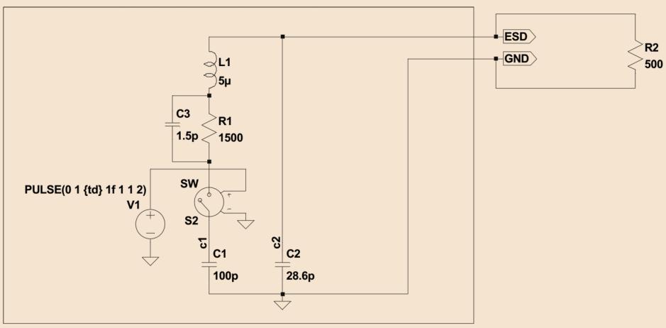
5 HBM Waveform * ANSI/ESDA/JEDEC JS , MIL-STD-883J Method ** 4


6 HMM Waveform * IEC , ISO 10605, MIL-STD-461G CS118, ANSI/ESD SP


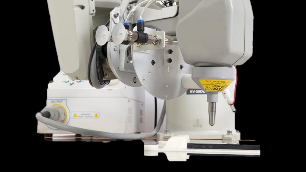
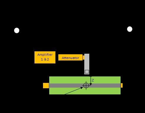
7 ESD Current Spreading Scanning Robot Scope Results Probe PC DUT TLP 6

8 Current Spreading on Microstrip 7

9 Current Spreading on Flex PCB 8

10 ANSI/ESD SP From ESDA: For Electrostatic Discharge Sensitivity Testing Near-Field Immunity Scanning Component/Module/PCB Level An American National Standard Approved September 14, 2015 ESD scanning technology is widely accepted as a powerful tool for root cause analysis and screening high immunity components, modules and systems * ANSI/ESD SP


11 ESD Immunity Scanning Robot Results FD PC Probe DUT TLP 10


12 TLP Waveform V TLP = 2 kv T r = 500 ps T f = 33 ns 11

13 Current Waveforms: HBM vs HMM vs TLP Simulated discharge current waveform on 2 Ω load * IEC
 Board dimension: 100 x 100 mm 2 Board elevation from HCP:")
 Board dimension: 100 x 100 mm 2 Probe: 2 mm or 5 mm loop H-field Mechanical")
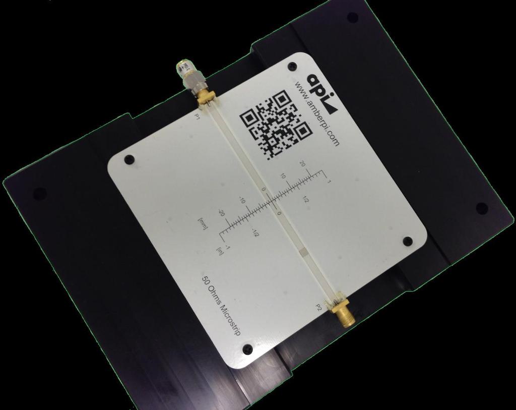
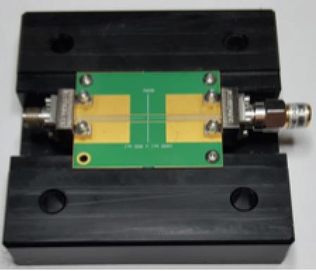
14 HMM vs ANSI/ESD SP Simple Structure? 50 ohms microstrip (3 mm wide trace) Board dimension: 100 x 100 mm 2 Board elevation from HCP: 1 mm ESD generator distance to board: 10 mm ESD generator setting: 2 kv CD 50 ohms microstrip (3 mm wide trace) Board dimension: 100 x 100 mm 2 Probe: 2 mm or 5 mm loop H-field Mechanical probe height from trace: 0 mm TLP setting: 2 kv 13


15 Field Coupling to Microstrip H-Field E-Field Surface Current Density 14

16 Field Attenuation from ESD 15

17 HMM vs Near-Field Injection 16

18 Effect of IC Fab on ESD White Paper 3 Part II specifically covers in detail an overview of system ESD stress app lication methods, system diagnostic techniques to detect hard or soft failures, and the application of tools for susceptibility scanning. For example, as illustrated in Figure 2, these types of advanced tools can be used to differentiate the characteristics of products and enable proper system protection methodology*. Figure 2: Susceptibility scanning using pulse techniques on Product A (left) and Product B (right) (Courtesy of Amber Precision Instruments) * Quote from the ESDA White paper 3, Part II, page 18. ** Product A and Product B are functionally identical ICs from different vendors. 17
19 Susceptibility Scanning: Conclusion Conducted susceptibility to an ESD even can be analyzed by measuring and visualizing scanned surface current density on the DUT. Susceptibility to near-field effects of an ESD event can be emulated with near-field injection. Near-field injection per ANSI/ESD SP reproduces same failures as IEC
20 Emission Scanning 19


21 EMI Near-Field Scanning Robot SA Results Probe PC DUT 20


22 EMI Near-Field Probe EMI Probes: - Up to 6 GHz - Up to 20 GHz - Up to 40 GHz Optional EMI Probes; Choose: - Size - Frequency range - Field Component * EMI Hx 2 mm 21

23 Characterization Structure 50 Ohms Microstrip Line (MSL) 50 Ohms Coplanar Waveguide 22
24 Probe Characterization Setup 23
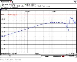
25 Typical EMI Probe S21 S21 [db] Frequency [Hz] x 10 9 * EMI Hx 2 mm: up to 10 GHz 24
26 What Are the Specs? Log freq: Low freq with 20 db/dec slope db/dec Line S21 [db] Frequency [Hz] 25
27 What Are the Specs? Unwanted field: Decoupling of unwanted components Hx Field, = 0 Unwanted Field, = S21 [db] Frequency [Hz] 26
28 Probe Factor Probe factor: Measure and calculate system factor 50 Measured Probe Factor Theoretical Open-Circuit Probe Factor PF [db(a/m)/v] Frequency [Hz] 27


29 Phase Measurement Scanning Robot VNA or Scope Results Probe PC DUT Ref Probe 28
30 Applications of Phase Measurement Phase Resolved Information Applications of Phase Measurement Near-Field to Far-Field Source Localization Emission Source Microscopy (ESM) Applications of ESM: - High speed data communication - Data centers, servers, switches, routers - 5G mobile network - Radar systems - Phased arrays - Electrically large structures 29
 Antenna Measuring")


, M.")
31 History of ESM: Synthetic Aperture Radar (SAR) Antenna Measuring instrument Use of imaging algorithm on measured data Scanning plane SUT Venus Magellan Probe GHz, 12.6 cm MRI Angiography Applications of SAR: - Airborne radar - Medical imaging - Concealed object detection - Non-destructive testing - Antenna diagnosis * Wikipedia, P.L. Ransom et al (1971), J.J Lee et al (1988), M. Soumekh (1991), D.M. Sheen et al (2001), B. Janice (2011), H. Kajbaf et al (2013) 30


 Ex @ Z=7.")
32 Non-Inverting Inverting Symmetric Differential Microstrip Load Full-wave simulation Differential microstrip line Differentially 10 GHz Z=1 mm (λ/30) Z=7.5 mm (λ/4) Z=30 mm (λ) 31
 Ex @ Z=7.")
33 Non-Inverting Inverting Asymmetric Differential Microstrip Load GND Asymmetric differential microstrip 12 mil gap between GND & line Differentially 10 GHz Z=1 mm (λ/30) Z=7.5 mm (λ/4) Z=30 mm (λ) 32

34 Wave Propagation Ex Ey Ez * Asymmetric differential 10 GHz E 33
 Z=30 mm (λ) Z=7.")

35 Wave Propagation Max Ex Max Ey Z=60 mm (2λ) Z=30 mm (λ) Z=7.5 mm (λ/4) Z=1 mm (λ/30) Max Ez * Asymmetric differential 10 GHz Max E 34
 Z=1 mm (λ/30) Max Ez * Symmetric differential microstrip @ 10")
36 Wave Propagation Max Ex Max Ey Z=60 mm (2λ) Z=30 mm (λ) Z=7.5 mm (λ/4) Z=1 mm (λ/30) Max Ez * Symmetric differential 10 GHz Max E 35
37 Emission Source Microscopy (ESM) f x, y = F 1 2D F 2D s x, y e jk zz 0 k z = k 2 k 2 2 x k y Optional: Calculate Far-Field Pattern Measure at Radiative Near-Field (~1-2λ away from DUT) Back-Calculate to DUT Location (Phase Adjustment)* Localize Sources Contributing to Far-Field Optional: Calculate TRP * Using Range Migration Algorithm (RMA) or Synthetic Aperture Radar (SAR) 36


 37")
38 k-space and Propagating Wave f x, y = F 1 2D F 2D s x, y e jk zz 0 k z = k 2 k x 2 k y 2 Scanned Ex k-space Focused Ex F 2D e jk zz 0 1 F 2D Scanned Ex k-space Focused Ex * Asymmetric differential 10 GHz, Z=30mm (λ) 37


")
39 k-space and Propagating Wave Scanned Ey k-space Focused Ey F 2D e jk zz 0 1 F 2D Scanned Ey k-space Focused Ey * Asymmetric differential 10 GHz, Z=30mm (λ) 38


40 k-space and Evanescent Wave Scanned Ex k-space Focused Ex F 2D e jk zz 0 1 F 2D Scanned Ex k-space Focused Ex * Asymmetric differential 10 GHz, Z=1mm (λ/30) 39


41 Improving Symmetry Scanned Ex Scanned Ey Focused Ex Focused Ey * Increasing gap between GND & line to 10 mm 40
 mm E fields components Frequency = 10 GHz Grid spacing = 0.5 mm Distance = 2.5λ Resolution ~ 15 mm 2.")
42 Ideal Dipole Interference pattern on scanning plane Two dipoles are placed Dipole 1 at (-100,0,0) mm, Dipole 2 at (100,0,100) mm E fields components Frequency = 10 GHz Grid spacing = 0.5 mm Distance = 2.5λ Resolution ~ 15 mm 2.5 λ Electric dipoles 41
 mm Dipole 2 at (100,0,100) mm")
43 Focusing Lens at Different Distances Correct location of dipoles is determined Dipole 1 at (-100,0,0) mm Dipole 2 at (100,0,100) mm 42
44 Resolution Numerical aperture is given as, NA = n sin θ where n = refractive index of medium θ = half of angular aperture Scanning plane d Source plane h Resolution is given as, R = λ 2 NA Theoretically, highest resolution is ~ λ/2 43
 to EMC - Identification of")


45 Applications of ESM ESM Application of Synthetic Aperture Antenna (SAR) to EMC - Identification of emission source - FF estimation - Total radiated power calculation 5 cm Away from DUT Focused Image Measurement Setup: - The measurement is performed at 8.2 GHz and at 5 cm away from DUT. - Using VNA and open-ended waveguide used. 44


46 Applications of ESM Radiated (dbm) Radiation Frequency(GHz) Near-Field 2 mm Open cover without absorber Scanning height = 7 cm Freq = GHz Scanned 7 cm Focused 0 cm 45


47 Applications of ESM Without absorbing material With absorbing material below ASIC With absorbing material around PHY With absorbing material around PHY and below ASIC TRP from R-Chamber Calculated From ESM Reduction in TRP 0-1 db 0-1 db TRP from R-Chamber Calculated From ESM Reduction in TRP 4-5 db 4-5 db 46
48 Emission Scanning: Conclusion EMI scanning is a powerful tool for identifying near-field sources. Measuring the phase distribution, in addition to magnitude, helps with identifying sources that contribute to far-field using ESM. Near-field to far-field transformation and total radiated power estimation are useful applications of phase measurement. 47
49 Thank You! Questions? Contact us: 48
Test and Measurement for EMC
 Test and Measurement for EMC Bogdan Adamczyk, Ph.D., in.c.e. Professor of Engineering Director of the Electromagnetic Compatibility Center Grand Valley State University, Michigan, USA Ottawa, Canada July
Todd H. Hubing Michelin Professor of Vehicular Electronics Clemson University
 Essential New Tools for EMC Diagnostics and Testing Todd H. Hubing Michelin Professor of Vehicular Electronics Clemson University Where is Clemson University? Clemson, South Carolina, USA Santa Clara Valley
EMC problems from Common Mode Noise on High Speed Differential Signals
 EMC problems from Common Mode Noise on High Speed Differential Signals Bruce Archambeault, PhD Alma Jaze, Sam Connor, Jay Diepenbrock IBM barch@us.ibm.com 1 Differential Signals Commonly used for high
Overview of EMC Regulations and Testing. Prof. Tzong-Lin Wu Department of Electrical Engineering National Taiwan University
 Overview of EMC Regulations and Testing Prof. Tzong-Lin Wu Department of Electrical Engineering National Taiwan University What is EMC Electro-Magnetic Compatibility ( 電磁相容 ) EMC EMI (Interference) Conducted
Presentation Abstract
 Presentation Abstract P1. IC to Victim Antenna Near-field Coupling Estimation - L. Li (S&T) In mixed radio-frequency (RF) and digital designs, noise from high-speed digital circuits can interfere with
A Comparison Between MIL-STD and Commercial EMC Requirements Part 2. By Vincent W. Greb President, EMC Integrity, Inc.
 A Comparison Between MIL-STD and Commercial EMC Requirements Part 2 By Vincent W. Greb President, EMC Integrity, Inc. OVERVIEW Compare and contrast military (i.e., MIL-STD) and commercial EMC immunity
Emission source microscopy for electromagnetic interference source localization
 Scholars' Mine Doctoral Dissertations Student Theses and Dissertations Summer 2014 Emission source microscopy for electromagnetic interference source localization Pratik Rajesh Maheshwari Follow this and
An Introduction to EMC Testing (what can be done with scopes) Vincent Lascoste EMC Product Manager - RSF
 Vincent Lascoste EMC Product Manager - RSF") An Introduction to EMC Testing (what can be done with scopes) Vincent Lascoste EMC Product Manager - RSF Definition of ElectroMagnetic Compatibility (EMC) EMC is defined as: "The ability of devices and
An Introduction to EMC Testing (what can be done with scopes) Vincent Lascoste EMC Product Manager - RSF Definition of ElectroMagnetic Compatibility (EMC) EMC is defined as: "The ability of devices and
Electromagnetic Compatibility
 Electromagnetic Compatibility Introduction to EMC International Standards Measurement Setups Emissions Applications for Switch-Mode Power Supplies Filters 1 What is EMC? A system is electromagnetic compatible
Test sites for EMC measurements
 Test sites for EMC measurements EMV Fachtagung 21. Januar 2014 Christophe Perrenoud www.montenaemc.ch montena emc Route de Montena 75 CH - 1728 Rossens Tel. +41 26 411 93 33 Fax +41 26 411 93 30 office.emc@montenaemc.ch
1000BASE-T1 EMC Test Specification for Common Mode Chokes
 IEEE 1000BASE-T1 EMC Test Specification for Common Mode Chokes Version 1.0 Author & Company Dr. Bernd Körber, FTZ Zwickau Title 1000BASE-T1 EMC Test Specification for Common Mode Chokes Version 1.0 Date
Course Introduction Purpose Objectives Content Learning Time
 Course Introduction Purpose This course discusses techniques for analyzing and eliminating noise in microcontroller (MCU) and microprocessor (MPU) based embedded systems. Objectives Learn about a method
EN 55015: 2013 Clause Pass. EN 55015: 2013 Clause Pass. EN 55015: 2013 Clause Pass
 Reference No.: WTD15S0730643E Page 2 of 42 1 Test Summary Test Item Conducted Disturbance at Mains Terminal, 9kHz to 30MHz Radiation electromagnetic disturbance, 9kHz to 30MHz Radiation Emission, 30MHz
Trees, vegetation, buildings etc.
 EMC Measurements Test Site Locations Open Area (Field) Test Site Obstruction Free Trees, vegetation, buildings etc. Chamber or Screened Room Smaller Equipments Attenuate external fields (about 100dB) External
Applications of 3D Electromagnetic Modeling in Magnetic Recording: ESD and Signal Integrity
 Applications of 3D Electromagnetic Modeling in Magnetic Recording: ESD and Signal Integrity CST NORTH AMERICAN USERS FORUM John Contreras 1 and Al Wallash 2 Hitachi Global Storage Technologies 1. San Jose
The Ground Myth IEEE. Bruce Archambeault, Ph.D. IBM Distinguished Engineer, IEEE Fellow 18 November 2008
 The Ground Myth Bruce Archambeault, Ph.D. IBM Distinguished Engineer, IEEE Fellow barch@us.ibm.com 18 November 2008 IEEE Introduction Electromagnetics can be scary Universities LOVE messy math EM is not
Micro- & Nano-technologies pour applications hyperfréquence à Thales Research &Technology Afshin Ziaei, Sébastien Demoustier, Eric Minoux
 Micro- & Nano-technologies pour applications hyperfréquence à Thales Research &Technology Afshin Ziaei, Sébastien Demoustier, Eric Minoux Outline Application hyperfréquence à THALES: Antenne à réseau réflecteur
AP7301 ELECTROMAGNETIC INTERFERENCE AND COMPATIBILITY L T P C COURSE OBJECTIVES:
 AP7301 ELECTROMAGNETIC INTERFERENCE AND COMPATIBILITY L T P C 3 0 0 3 COURSE OBJECTIVES: To understand the basics of EMI To study EMI Sources To understand EMI problems To understand Solution methods in
Localization and Identifying EMC interference Sources of a Microwave Transmission Module
 Localization and Identifying EMC interference Sources of a Microwave Transmission Module Ph. Descamps 1, G. Ngamani-Njomkoue 2, D. Pasquet 1, C. Tolant 2, D. Lesénéchal 1 and P. Eudeline 2 1 LaMIPS, Laboratoire
Automated Near-Field Scanning to Identify Resonances
 Automated Near-Field Scanning to Identify Resonances Muchaidze, Giorgi (1), Huang Wei (2), Jin Min (1), Shao Peng (2), Jim Drewniak (2) and David Pommerenke (2) (1) Amber Precision Instruments Santa Clara,
We re In The Business Of Making Your Life Easier
 Systems RF Conducted Immunity System We re In The Business Of Making Your Life Easier AS00202 4 khz 200 MHz System AS03007 10 khz 3 GHz System RF Conducted Immunity Testing to IEC, Military & Automotive
This annex is valid from: to Replaces annex dated: Location(s) where activities are performed under accreditation
 where activities are performed under accreditation") Location(s) where activities are performed under accreditation Head ffice Vijzelmolenlaan 7 3447 GX oerden The Netherlands Location Abbreviation/ location Vijzelmolenlaan 7 3447 GX oerden The Netherlands
Location(s) where activities are performed under accreditation Head ffice Vijzelmolenlaan 7 3447 GX oerden The Netherlands Location Abbreviation/ location Vijzelmolenlaan 7 3447 GX oerden The Netherlands
A Measurement Technique for ESD Current Spreading on A PCB using Near Field Scanning
 A Measurement Technique for ESD Current Spreading on A PCB using Near Field Scanning Wei Huang #, David Pommerenke #, Jiang Xiao #, Dazhao Liu #, Jin Min *2, Giorgi Muchaidze *2, Soonjae Kwon #3, Ki Hyuk
How EMxpert Diagnoses Board-Level EMC Design Issues
 Application Report EMxpert July 2011 - Cédric Caudron How EMxpert Diagnoses Board-Level EMC Design Issues ABSTRACT EMxpert provides board-level design teams with world-leading fast magnetic very-near-field
Understanding and Optimizing Electromagnetic Compatibility in Switchmode Power Supplies
 Understanding and Optimizing Electromagnetic Compatibility in Switchmode Power Supplies 1 Definitions EMI = Electro Magnetic Interference EMC = Electro Magnetic Compatibility (No EMI) Three Components
This annex is valid from: to Replaces annex dated: Location(s) where activities are performed under accreditation
 where activities are performed under accreditation") Normative document: EN IS/IEC 17025:2005 Location(s) where activities are performed under accreditation Head ffice Vijzelmolenlaan 7 3447 GX oerden The Netherlands Location Abbreviation/ location Vijzelmolenlaan
Normative document: EN IS/IEC 17025:2005 Location(s) where activities are performed under accreditation Head ffice Vijzelmolenlaan 7 3447 GX oerden The Netherlands Location Abbreviation/ location Vijzelmolenlaan
CHAPTER 6 EMI EMC MEASUREMENTS AND STANDARDS FOR TRACKED VEHICLES (MIL APPLICATION)
") 147 CHAPTER 6 EMI EMC MEASUREMENTS AND STANDARDS FOR TRACKED VEHICLES (MIL APPLICATION) 6.1 INTRODUCTION The electrical and electronic devices, circuits and systems are capable of emitting the electromagnetic
147 CHAPTER 6 EMI EMC MEASUREMENTS AND STANDARDS FOR TRACKED VEHICLES (MIL APPLICATION) 6.1 INTRODUCTION The electrical and electronic devices, circuits and systems are capable of emitting the electromagnetic
Schlöder GmbH - EMC Test and Measurement Systems Model #
 Schlöder GmbH - EMC Test and Measurement Systems Model # Product Description IEC / EN 61000-4 - 2 ESD SESD 216 ESD generator 10 kv CON / 16,5 kv AIR acc. to IEC 61000-4-2, 150 pf / 330 ohm SESD 230 ESD
FlexRay Communications System. Physical Layer Common mode Choke EMC Evaluation Specification. Version 2.1
 FlexRay Communications System Physical Layer Common mode Choke EMC Evaluation Specification Version 2.1 Disclaimer DISCLAIMER This specification as released by the FlexRay Consortium is intended for the
Design for Guaranteed EMC Compliance
 Clemson Vehicular Electronics Laboratory Reliable Automotive Electronics Automotive EMC Workshop April 29, 2013 Design for Guaranteed EMC Compliance Todd Hubing Clemson University EMC Requirements and
P331-2 set ESD generator (IEC )
") User manual Probe set set ESD generator (IEC 61000-4-2) Copyright January 2017 LANGER GmbH 2017.01.09 User manual Table of contents: Page 1 ESD generator (IEC 61000-4-2) 3 1.1 Design and function of the
User manual Probe set set ESD generator (IEC 61000-4-2) Copyright January 2017 LANGER GmbH 2017.01.09 User manual Table of contents: Page 1 ESD generator (IEC 61000-4-2) 3 1.1 Design and function of the
END OF LIFE. Product Specification PE64908 RF- RF+ CMOS Control Driver and ESD. Product Description
 Product Description PE64908 is a DuNE technology-enhanced Digitally Tunable Capacitor (DTC) based on Peregrine s UltraCMOS technology.this highly versatile product supports a wide variety of tuning circuit
EMC Near-field Probes + Wideband Amplifier
 1 Introduction The H20, H10, H5 and E5 are magnetic field (H) and electric field (E) probes for radiated emissions EMC precompliance measurements. The probes are used in the near field of sources of electromagnetic
EMC Seminar Series All about EMC Testing and Measurement Seminar 1
 EMC Seminar Series All about EMC Testing and Measurement Seminar 1 Introduction to EMC Conducted Immunity Jeffrey Tsang Organized by : Department of Electronic Engineering 1 Basic Immunity Standards: IEC
Student Research & Creative Works
 Scholars' Mine Masters Theses Student Research & Creative Works Spring 2017 Characterization of the rectification behaviour of in-amps and estimating the near field coupling from SMPS circuits to a nearby
2620 Modular Measurement and Control System
 European Union (EU) Council Directive 89/336/EEC Electromagnetic Compatibility (EMC) Test Report 2620 Modular Measurement and Control System Sensoray March 31, 2006 April 4, 2006 Tests Conducted by: ElectroMagnetic
Description RF Explorer RFEAH-25 1 is a 25mm diameter, high performance near field H-Loop antenna.
 Description RF Explorer RFEAH-25 1 is a 25mm diameter, high performance near field H-Loop antenna. RFEAH-25 is a very sensitive, compact and easy to use H-loop near field antenna. The low-loss design exhibits
SP814x Series 1.0pF 22KV Diode Array
 SP814x Series 1.pF 22KV Diode Array RoHS Pb GREEN Description The SP814x series integrates 4 or 6 channels of ultra low capacitance rail-to-rail diodes and an additional zener diode to provide protection
Unleash SiC MOSFETs Extract the Best Performance
 Unleash SiC MOSFETs Extract the Best Performance Xuning Zhang, Gin Sheh, Levi Gant and Sujit Banerjee Monolith Semiconductor Inc. 1 Outline SiC devices performance advantages Accurate test & measurement
EMC TEST REPORT. NORTE SIRIUS ENTERPRISE CO., LTD , Shin-Sheng St., Chung-Ho Dist, New Taipei City, Taiwan
 Page 1 of 32 EMC TEST REPORT Report No.: TS11020117-EME Model No.: NS-PSE, NS-POINTED, NS-PSQUARE, NS-PF-S, NS-PT, NS-PR, NS-PU, NS-PF-H, NS-BALIBA, NS-FLEXMA Issued Date: Mar. 01, 2011 Applicant: NORTE
Prof. dr. ir. Johan CATRYSSE
 EMC: How to handle large machinery Prof. dr. ir. Johan CATRYSSE FMEC, KHBO, Oostende (BE) MICAS/ESAT, KULeuven (BE) 1 Overview 2 Large Machinery EMC Directive and Harmonised Standards TEMCA2 project Conducted
Overview. Measurement of Ultra-Wideband Wireless Channels
 Measurement of Ultra-Wideband Wireless Channels Wasim Malik, Ben Allen, David Edwards, UK Introduction History of UWB Modern UWB Antenna Measurements Candidate UWB elements Radiation patterns Propagation
Keysight Technologies Signal Integrity Tips and Techniques Using TDR, VNA and Modeling
 Keysight Technologies Signal Integrity Tips and Techniques Using, VNA and Modeling Article Reprint This article first appeared in the March 216 edition of Microwave Journal. Reprinted with kind permission
MediSpec SMI Non-Magnetic Transceiver
 The MediSpec SMI is an RCLED based 650nm solution enabling robust and reliable termination of Plastic Optical Fiber (POF) The optical transceiver is designed to provide up to 250 Mbps data communication
EMI. Chris Herrick. Applications Engineer
 Fundamentals of EMI Chris Herrick Ansoft Applications Engineer Three Basic Elements of EMC Conduction Coupling process EMI source Emission Space & Field Conductive Capacitive Inductive Radiative Low, Middle
Improve Performance and Reliability with Flexible, Ultra Robust MEMS Oscillators
 Field Programmable Timing Solutions Improve Performance and Reliability with Flexible, Ultra Robust MEMS Oscillators Reference timing components, such as resonators and oscillators, are used in electronic
EMC TEST REPORT For MPP SOLAR INC Inverter/ Charger Model Number : PIP 4048HS
 EMC-E20130903E EMC TEST REPORT For MPP SOLAR INC Inverter/ Charger Model Number : PIP 4048HS Prepared for : MPP SOLAR INC Address : 4F, NO. 50-1, SECTION 1, HSIN-SHENG S. RD. TAIPEI, TAIWAN Prepared by
Laird Attn: Bill Steinike W66 N220 Commerce Ct. Cedarburg, WI Report Constructed by: Zach Wilson, EMC Technician Signature: Date: June 21, 2017
 A Test Report # 317241 Equipment Under Test: RM024 Test Date(s): June 9 and June 21, 2017 Prepared for: Laird Attn: Bill Steinike W66 N220 Commerce Ct. Cedarburg, WI 53012 Report Issued by: Adam Alger,
UM Line ESD/EMI Protection for Color LCD Interfaces DFN General Description. Rev.10 Mar.
 8 Line ESD/EMI Protection for Color LCD Interfaces UM8401 DFN16 4.0 1.6 General Description The UM8401 is a low pass filter array with integrated TVS diodes. It is designed to suppress unwanted EMI/RFI
Further Refining and Validation of RF Absorber Approximation Equations for Anechoic Chamber Predictions
 Further Refining and Validation of RF Absorber Approximation Equations for Anechoic Chamber Predictions Vince Rodriguez, NSI-MI Technologies, Suwanee, Georgia, USA, vrodriguez@nsi-mi.com Abstract Indoor
FISCHER CUSTOM COMMUNICATIONS, INC.
 FISCHER CUSTOM COMMUNICATIONS, INC. Current Probe Catalog FISCHER CUSTOM COMMUNICATIONS, INC. Fischer Custom Communications, Inc., is a manufacturer of custom electric and magnetic field sensors for military
IEEE Electromagnetic Compatibility Standards (Active & Archive) Collection: VuSpec
 Collection: VuSpec") IEEE Electromagnetic Compatibility Standards (Active & Archive) Collection: VuSpec This value-packed VuSpec represents the most complete resource available for professional engineers looking for best practices
IEEE Electromagnetic Compatibility Standards (Active & Archive) Collection: VuSpec This value-packed VuSpec represents the most complete resource available for professional engineers looking for best practices
Predicting and Controlling Common Mode Noise from High Speed Differential Signals
 Predicting and Controlling Common Mode Noise from High Speed Differential Signals Bruce Archambeault, Ph.D. IEEE Fellow, inarte Certified Master EMC Design Engineer, Missouri University of Science & Technology
PESD1LIN. 1. Product profile. LIN bus ESD protection diode in SOD General description. 1.2 Features. 1.3 Applications. Quick reference data
 Rev. 01 26 October 2004 Product data sheet 1. Product profile 1.1 General description in very small SOD323 (SC-76) SMD plastic package designed to protect one automotive LIN bus line from the damage caused
For the National Voluntary Laboratory Accreditation Program
 SCOPE OF ACCREDITATION TO ISO/IEC 17025:2005 Intertek Japan K.K. Calibration Laboratory 3-2 Sunayama Kamisu Ibaraki 314-0255 JAPAN Ms. Masako Oyamada Phone: 81-465 89 2316 Fax: 81-465 89 2160 E-mail: masako.oyamada@intertek.com
ESDARF02-1BU2CK. Single-line bidirectional ESD protection for high speed interface. Features. Applications. Description
 Single-line bidirectional ESD protection for high speed interface Features Datasheet production data Bidirectional device Extra low diode capacitance: 0.2 pf Low leakage current 0201 SMD package size compatible
3 * ESD5302N ESD5302N. Descriptions. Features. Applications. Order information. http//:
 2-Lines, Uni-directional, Ultra-low Capacitance Transient Voltage Suppressors http//:www.sh-willsemi.com Descriptions The is an ultra-low capacitance TVS (Transient Voltage Suppressor) array designed to
EMC Overview. What is EMC? Why is it Important? Case Studies. Examples of calculations used in EMC. EMC Overview 1
 EMC Overview What is EMC? Why is it Important? Case Studies. Examples of calculations used in EMC. EMC Overview 1 What Is EMC? Electromagnetic Compatibility (EMC): The process of determining the interaction
CS114 + CS115 + CS116
 System description Test Setup for MIL-STD-461 D, E&F CS114 + CS115 + CS116 1. MONTENA EMC... 2 1.1 PRODUCTS... 3 1.2 TURN KEY MIL STD 461 TEST INSTALLATIONS... 3 2. TEST SETUP DESCRIPTION... 4 2.1 TEST
Differential Signaling is the Opiate of the Masses
 Differential Signaling is the Opiate of the Masses Sam Connor Distinguished Lecturer for the IEEE EMC Society 2012-13 IBM Systems & Technology Group, Research Triangle Park, NC My Background BSEE, University
Calibration and Validation for Automotive EMC
 Calibration and Validation for Automotive EMC Wolfgang Müllner Patrick Preiner Alexander Kriz Seibersdorf Labor GmbH 2444 Seibersdorf, Austria http://rf.seibersdorf-laboratories.at rf@seibersdorf-laboratories.at
An Analysis of the Fields on the Horizontal Coupling Plane in ESD testing
 An Analysis of the Fields on the Horizontal Coupling Plane in ESD testing Stephan Frei David Pommerenke Technical University Berlin, Einsteinufer 11, 10597 Berlin, Germany Hewlett Packard, 8000 Foothills
Harmonizing the ANSI-C12.1(2008) EMC Tests. Harmonizing the ANSI-C12.1(2008) EMC Tests
 EMC Tests. Harmonizing the ANSI-C12.1(2008) EMC Tests") Harmonizing the ANSI-C12.1(2008) EMC Tests Subcommittee 1 (Emissions) Subcommittee 5 (Immunity) Joint Task Force on C12.1 June 17, 2013 1 The Accredited Standards Committee C63 presents Harmonizing the
Harmonizing the ANSI-C12.1(2008) EMC Tests Subcommittee 1 (Emissions) Subcommittee 5 (Immunity) Joint Task Force on C12.1 June 17, 2013 1 The Accredited Standards Committee C63 presents Harmonizing the
Impact of NFSI on the clock circuit of a Gigabit Ethernet switch
 Impact of NFSI on the clock circuit of a Gigabit Ethernet switch Massiva Zouaoui, Etienne Sicard, Henri Braquet, Ghislain Rudelou, Emmanuel Marsy and Gilles Jacquemod CONTENTS 1. Context 2. Objectives
PGB2 Series Halogen Free / Lead-Free
 Halogen Free / Lead-Free Description PulseGuard ESD Suppressors help protect sensitive electronic equipment against electrostatic discharge (ESD). They use polymer composite materials to suppress fastrising
6V8 * ESDA6V8UD ESDA6V8UD. Descriptions. Features. Order information. Applications. http//:
 4-Lines, Uni-directional, Ultra-low Capacitance Transient Voltage Suppressors http//:www.sh-willsemi.com Descriptions The is an ultra-low capacitance TVS (Transient Voltage Suppressor) array designed to
EMI measurement and modeling techniques for complex electronic circuits and modules
 Scholars' Mine Doctoral Dissertations Student Theses and Dissertations Summer 2017 EMI measurement and modeling techniques for complex electronic circuits and modules Satyajeet Shinde Follow this and additional
arxiv:physics/ v1 [physics.optics] 28 Sep 2005
![arxiv:physics/ v1 [physics.optics] 28 Sep 2005](/thumbs/91/105523130.jpg "arxiv:physics/ v1 [physics.optics] 28 Sep 2005") Near-field enhancement and imaging in double cylindrical polariton-resonant structures: Enlarging perfect lens Pekka Alitalo, Stanislav Maslovski, and Sergei Tretyakov arxiv:physics/0509232v1 [physics.optics]
Near-field enhancement and imaging in double cylindrical polariton-resonant structures: Enlarging perfect lens Pekka Alitalo, Stanislav Maslovski, and Sergei Tretyakov arxiv:physics/0509232v1 [physics.optics]
EMC of Analog Integrated Circuits
 Jean-Michel Redoute Michiel Steyaert EMC of Analog Integrated Circuits ^J Springer Contents 1. INTRODUCTION 1 1 The pioneers of wireless communication 1 2 Evolution of awareness of electromagnetic compatibility
High Speed Characterization Report
 SSW-1XX-22-X-D-VS Mates with TSM-1XX-1-X-DV-X Description: Surface Mount Terminal Strip,.1 [2.54mm] Pitch, 13.59mm (.535 ) Stack Height Samtec, Inc. 25 All Rights Reserved Table of Contents Connector Overview...
7. EMV Fachtagung. EMV-gerechtes Filterdesign. 23. April 2009, TU-Graz. Dr. Gunter Winkler (TU Graz) Dr. Bernd Deutschmann (Infineon Technologies AG)
 Dr. Bernd Deutschmann (Infineon Technologies AG)") 7. EMV Fachtagung 23. April 2009, TU-Graz EMV-gerechtes Filterdesign Dr. Gunter Winkler (TU Graz) Dr. Bernd Deutschmann (Infineon Technologies AG) Page 1 Agenda Filter design basics Filter Attenuation
7. EMV Fachtagung 23. April 2009, TU-Graz EMV-gerechtes Filterdesign Dr. Gunter Winkler (TU Graz) Dr. Bernd Deutschmann (Infineon Technologies AG) Page 1 Agenda Filter design basics Filter Attenuation
Advanced Topics in EMC Design. Issue 1: The ground plane to split or not to split?
 NEEDS 2006 workshop Advanced Topics in EMC Design Tim Williams Elmac Services C o n s u l t a n c y a n d t r a i n i n g i n e l e c t r o m a g n e t i c c o m p a t i b i l i t y e-mail timw@elmac.co.uk
EMI AND BEL MAGNETIC ICM
 EMI AND BEL MAGNETIC ICM ABSTRACT Electromagnetic interference (EMI) in a local area network (LAN) system is a common problem that every LAN system designer faces, and it is a growing problem because the
1. Electro-Static Discharge Test EN R Radiated Susceptibility Test EN R-2
 INDEX PAGE 1. Electro-Static Discharge Test EN61000-4-2.. R-1 2. Radiated Susceptibility Test EN61000-4-3 R-2 3. Electrical Fast Transient Burst Test EN61000-4-4 R-3 4. Surge Test EN61000-4-5 R-4 5. Conducted
Harmonic Current emission EN :2014 Class A Pass. Voltage Fluctuation and Flicker EN :2013 Clause 5 Pass
 Reference No.: WTS15F0323845E Page 2 of 33 1 Test Summary Test Item Mains Terminal Disturbance Voltage, 148.5kHz to 30MHz Disturbance Power, 30MHz to 300MHz Discontinuous Disturbance (Click) Radiated Emission,
Introduction EMC. Filter parameters. Definition of EMC / EMI. X-Capacitor. Sources of EMI. Coupling mechanism. Y-Capacitor.
 Introduction to EMC Schurter has over 75 years experience in the electronics and electrical industries, developing and manufacturing components that ensure a clean and safe supply of power. Schurter provides
GHz Power Amplifier. GaAs Monolithic Microwave IC in SMD leadless package
 GaAs Monolithic Microwave IC in SMD leadless package Description The is a four stage monolithic GaAs high power amplifier producing 1 Watt output power. It is highly linear, with possible gain control
Broadband covering primary wireless communications bands: Cellular, PCS, LTE, WiMAX
 Ultra Linear Low Noise Monolithic Amplifier 50Ω 0.05 to 4 GHz The Big Deal Ultra High IP3 Broadband High Dynamic Range May be used as a replacement for RFMD SPF-5189Z a,b SOT-89 PACKAGE Product Overview
Taking the Mystery out of Signal Integrity
 Slide - 1 Jan 2002 Taking the Mystery out of Signal Integrity Dr. Eric Bogatin, CTO, GigaTest Labs Signal Integrity Engineering and Training 134 S. Wolfe Rd Sunnyvale, CA 94086 408-524-2700 www.gigatest.com
FT01MHNG FT01MVNG. 530 nm DC-1 MBd RedLink Fiber Optic Transmitter Datasheet DESCRIPTION FEATURES APPLICATIONS AVAILABLE OPTIONS
 FT01MHNG FT01MVNG 530 nm DC-1 MBd RedLink Fiber Optic Transmitter Datasheet DESCRIPTION The Firecomms DC to 1 MBd green 530 nm transmitter is designed for maximum distance at low speed communication in
5V 4 * 1 5 ESD5344D ESD5344D. Descriptions. Features. Order information. Applications. http//:www.sh-willsemi.com
 ESD5344D 4-Lines, Uni-directional, Ultra-low Capacitance Transient Voltage Suppressors http//:www.sh-willsemi.com Descriptions The ESD5344D is an ultra-low capacitance TVS (Transient Voltage Suppressor)
06-496r3 SAS-2 Electrical Specification Proposal. Kevin Witt SAS-2 Phy Working Group 1/16/07
 06-496r3 SAS-2 Electrical Specification Proposal Kevin Witt SAS-2 Phy Working Group 1/16/07 Overview Motivation Multiple SAS-2 Test Chips Have Been Built and Tested, SAS-2 Product Designs have Started
Efficient and quantitative emc predictions (emission and immunity) for ECU modules
 for ECU modules") Scholars' Mine Doctoral Dissertations Student Theses and Dissertations Fall 2016 Efficient and quantitative emc predictions (emission and immunity) for ECU modules Guangyao Shen Follow this and additional
Scholars' Mine Doctoral Dissertations Student Theses and Dissertations Fall 2016 Efficient and quantitative emc predictions (emission and immunity) for ECU modules Guangyao Shen Follow this and additional
Guidance and Declaration - Electromagnetic Compatibility (EMC) for the Delfi PTS ii Portable Tourniquet System
 for the Delfi PTS ii Portable Tourniquet System") Guidance and Declaration - Electromagnetic Compatibility (EMC) for the Delfi TS ii ortable Tourniquet System Guidance and manufacturer s declaration electromagnetic emissions The TS ii ortable Tourniquet
Guidance and Declaration - Electromagnetic Compatibility (EMC) for the Delfi TS ii ortable Tourniquet System Guidance and manufacturer s declaration electromagnetic emissions The TS ii ortable Tourniquet
EMC/EMI MEASURING INSTRUMENTS & ACCESSORIES SHORT-FORM CATALOG 2011
 EMC/EMI MEASURING INSTRUMENTS & ACCESSORIES SHORT-FORM CATALOG 2011 All-in-one Digital EMI Analyzer 10 Hz - 3 GHz PMM 9010/30P EMI Analyzer 10 Hz - 3 GHz Our trek started in a small laboratory over 25
Finding the root cause of an ESD upset event
 DesignCon 2006 Finding the root cause of an ESD upset event David Pommerenke, University Missouri Rolla Pommerenke@eceumr.edu 573 341-4531 Jayong Koo Giorgi Muchaidze Abstract System level Electrostatic
Downloaded from 1. THE FOLLOWING PAGES OF MIL-STD-462D HAVE BEEN REVISED AND SUPERSEDE THE PAGES LISTED:
 NOTICE OF CHANGE METRIC 10 April 1995 MILITARY STANDARD MEASUREMENT OF ELECTROMAGNETIC INTERFERENCE CHARACTERISTICS TO ALL HOLDERS OF : 1. THE FOLLOWING PAGES OF HAVE BEEN REVISED AND SUPERSEDE THE PAGES
Development of a noval Switched Beam Antenna for Communications
 Master Thesis Presentation Development of a noval Switched Beam Antenna for Communications By Ashraf Abuelhaija Supervised by Prof. Dr.-Ing. Klaus Solbach Institute of Microwave and RF Technology Department
ACCREDITED LABORATORY. LIBERTY LABS, INC. Kimballton, IA for technical competence in the field of Calibration
 THE AMERICAN ASSOCIATION FOR LABORATORY ACCREDITATION ACCREDITED LABORATORY A2LA has accredited LIBERTY LABS, INC. Kimballton, IA for technical competence in the field of Calibration The accreditation
EMC review for Belle II (Grounding & shielding plans) PXD DEPFET system
 PXD DEPFET system") EMC review for Belle II (Grounding & shielding plans) PXD DEPFET system Outline 1. Introduction 2. Grounding strategy Implementation aspects 3. Noise emission issues Test plans 4. Noise immunity issues
EMC review for Belle II (Grounding & shielding plans) PXD DEPFET system Outline 1. Introduction 2. Grounding strategy Implementation aspects 3. Noise emission issues Test plans 4. Noise immunity issues
SHF Communication Technologies AG. Wilhelm-von-Siemens-Str. 23D Berlin Germany. Phone Fax
 SHF Communication Technologies AG Wilhelm-von-Siemens-Str. 23D 12277 Berlin Germany Phone +49 30 772 051-0 Fax +49 30 753 10 78 E-Mail: sales@shf-communication.com Web: www.shf-communication.com Datasheet
Electromagnetic and Radio Frequency Interference (EMI/RFI) Considerations For Nuclear Power Plant Upgrades
 Considerations For Nuclear Power Plant Upgrades") Electromagnetic and Radio Frequency Interference (EMI/RFI) Considerations For Nuclear Power Plant Upgrades November 9, 2016 Presented to: Presented by: Chad Kiger EMC Engineering Manager ckiger@ams-corp.com
Electromagnetic and Radio Frequency Interference (EMI/RFI) Considerations For Nuclear Power Plant Upgrades November 9, 2016 Presented to: Presented by: Chad Kiger EMC Engineering Manager ckiger@ams-corp.com
Dr. Ali Muqaibel. Associate Professor. Electrical Engineering Department King Fahd University of Petroleum & Minerals Dhahran, Saudi Arabia
 By Associate Professor Electrical Engineering Department King Fahd University of Petroleum & Minerals Dhahran, Saudi Arabia Wednesday, December 1, 14 1 st Saudi Symposium for RADAR Technology 9 1 December
EM Noise Mitigation in Electronic Circuit Boards and Enclosures
 EM Noise Mitigation in Electronic Circuit Boards and Enclosures Omar M. Ramahi, Lin Li, Xin Wu, Vijaya Chebolu, Vinay Subramanian, Telesphor Kamgaing, Tom Antonsen, Ed Ott, and Steve Anlage A. James Clark
Radio frequency interference (RFI) modeling of complex modules in mobile devices and systemlevel modeling for transient ESD simulation
 modeling of complex modules in mobile devices and systemlevel modeling for transient ESD simulation") Scholars' Mine Doctoral Dissertations Student Research & Creative Works Fall 2014 Radio frequency interference (RFI) modeling of complex modules in mobile devices and systemlevel modeling for transient
Scholars' Mine Doctoral Dissertations Student Research & Creative Works Fall 2014 Radio frequency interference (RFI) modeling of complex modules in mobile devices and systemlevel modeling for transient
Determining The Size Of Cabinet Apertures For Effectively Mitigating Radiated Emissions. By David Norte Thursday, April 7 th, 2005
 The EMC, Signal And Power Integrity Institute Presents Determining The Size Of Cabinet Apertures For Effectively Mitigating Radiated Emissions By David Norte Thursday, April 7 th, 2005 1 Motivation For
SPLVDS032RH. Quad LVDS Line Receiver with Extended Common Mode FEATURES DESCRIPTION PIN DIAGRAM. Preliminary Datasheet June
 FEATURES DESCRIPTION DC to 400 Mbps / 200 MHz low noise, low skew, low power operation - 400 ps (max) channel-to-channel skew - 300 ps (max) pulse skew - 7 ma (max) power supply current LVDS inputs conform
BROADBAND GAIN STANDARDS FOR WIRELESS MEASUREMENTS
 BROADBAND GAIN STANDARDS FOR WIRELESS MEASUREMENTS James D. Huff Carl W. Sirles The Howland Company, Inc. 4540 Atwater Court, Suite 107 Buford, Georgia 30518 USA Abstract Total Radiated Power (TRP) and
Common myths, fallacies and misconceptions in Electromagnetic Compatibility and their correction.
 Common myths, fallacies and misconceptions in Electromagnetic Compatibility and their correction. D. A. Weston EMC Consulting Inc 22-3-2010 These are some of the commonly held beliefs about EMC which are
AFBR-59F2Z Data Sheet Description Features Applications Transmitter Receiver Package
 AFBR-59F2Z 2MBd Compact 6nm Transceiver for Data communication over Polymer Optical Fiber (POF) cables with a bare fiber locking system Data Sheet Description The Avago Technologies AFBR-59F2Z transceiver