ELECTRICAL TESTING AND SAFETY
|
|
|
- Gabriel Perry
- 6 years ago
- Views:
Transcription
1 ELECTRICAL TESTING AND SAFETY Electrical installation testing The risks linked to incorrect use of electricity may include: -life-threatening danger for people, -threat of damage to electrical installations and property, -harmful effects on systems operation and equipment life spans. So the purpose of electrical installation testing is primarily to ensure that people and goods are kept safe and are protected in the event of a fault. It also facilitates preventive maintenance of installations, preventing serious faults which might prove expensive (production shutdown, etc.). To guarantee people's safety with regard to these installations and the electrical equipment connected to them, standards have naturally been developed and updated to take changes into account. The IEC standard and its various national equivalents published in each European country, such as NF C in France or VDE 100 in Germany, specify the requirements concerning electrical installations in buildings. Chapter 6 of this standard describes the requirements for testing the compliance of an installation. The effectiveness of the safety measures implemented can only be guaranteed if regular tests prove they are operating correctly. This is why the standards cover not only the initial verifications when installations are commissioned, but also periodic testing whose frequency depends on the type of installation and equipment, its use and the legislation in the country involved. In addition, the tests must be carried out with measurement instruments that comply with the IEC European standard ensuring user safety and reliable measurements. The electrical testing is divided into 2 parts: 1. Visual inspection to guarantee that the installation complies with the safety requirements (presence of an earth electrode, protective devices, etc.) and does not show any visible evidence of damage. 2. Measurements There are 4 main measurements required: 1. Earth 2. Insulation 3. Continuity 4. Tests of protective devices 1. earth To guarantee safety on residential or industrial electrical installations, there must be an earth electrode. If there is no earth electrode, it may endanger people's lives and damage electrical installations and property. When a large enough area is available to set up stakes, you should measure the earth with the traditional 3-pole method, also known as the 62 % method. When the 62 % method is not applicable, however, other methods can be used. There are many methods for measuring the earth, some more suitable than others, depending on the neutral system, the type of installation (residential, industrial, urban, rural, etc.), the possibility of cutting off the power, the area available for planting stakes, etc. 2. CONTINUITY The purpose of continuity measurement is to check the continuity of the protective conductors and the main and supplementary equipotential bonds. The test is carried out using a measurement instrument capable of generating a no-load voltage of 4 to 24 V (DC or AC) with a minimal current of 200 ma. The resistance measured must be lower than a threshold specified by the standard applicable to the installation tested, which is usually 2 Ω. As the resistance value is low, the resistance of the measurement leads must be compensated, particularly if very long leads are used. 3. insulation Good insulation is essential to prevent electric shocks. This measurement, usually carried out between active conductors and the earth, involves injecting a DC voltage, measuring the current and thus determining the insulation resistance value. The power must be switched off and the installation must be disconnected before performing this test to ensure that the test voltage will not be applied to other equipment electrically connected to the circuit to be tested, particularly devices sensitive to voltage surges. According to the IEC standard, the minimum insulation resistance values must be as follows: Rated voltage of circuit DC test voltage Insulation resistance V V MΩ LV secondary switchboard or LV main switchboard Less than or equal to 500 V including LV main switchboard Greater than 500 V 1, TESTS OF PROTECTIVE DEVICES - Fuses / Circuit-breakers To check the specifications of the protective devices such as fuses or circuitbreakers, a fault loop impedance measurement is carried out to calculate the corresponding short-circuit current. A visual inspection can then be used to check that the sizing is correct. - Residual current devices (RCDs) RCDs, which detect earth leakage currents, can be tested using two methods: - the basic test, also called a pulse test, which determines the trip time (in milliseconds) - the step test, which determines the trip time and trip current, thus detecting any RCD ageing. Page z 36
2 Installation tester selection guide C.A 6030 C.A 6454 Insulation Bipolar n n n Automatic L-N-PE n 100 / 250 / 500 V n n 50 / 100 / 250 / 500 / 1,000 V n RCD Tests Non-trip test n n n n Trip time n n n n Trip current n n n n Earth 2P / 3P method without voltage n n 1P live-line method n n n n n n 1-clamp selective method n n n n Loop impedance & resistance L-PE n n n n n n L-L n n n n n L-N n n n n n Ip-p calculation n n n n n n Continuity Manual n n Manual automatic n Phase rotation n n n n Current / Leakage current n n n n n Active power n Harmonic n Voltage n n n n n n Frequency n n n n n n Wiring polarity: Test + Reversal n n n n n n Alarms n n n n n n Memory n n n n n n Communication output n n n n n n Display n n n n n n LCD screen n n n n n Graphic screen n Batteries n n n Rechargeable batteries n n n Software DataView n Others n n n n n Page C.A 6456 C.A 6114 C.A 6115N C.A 6116 Portable, on-site and laboratory test and measurement instruments z 2010 catalogue Page z 37
3 ELECTRICAL TESTING AND SAFETY Installation tester > C.A 6030 z Comprehensive, accurate testing of RCD status z Earth loop measurement C.A 6030 IEC V CAT III Voltage Frequency Wiring polarity: testing + reversal RCD tests Rated voltage / frequency of the installation IΔn Non-trip time Trip time Trip current L-PE loop (without RCD tripping) Rated voltage / frequency of the installation Measurement current Calculation of short-circuit current (Isc) Live-line earth measurement (1 stake) (without tripping RCD > 30 ma) Rated voltage / frequency of the installation Measurement current Phase rotation Current / leakage current (Using a current clamp option) MN20 clamp C172 clamp C176 clamp Compensation of cables Alarms Storage Communication output Display z C.A to 550 V (DC or RMS) as soon as the instrument is connected 15.3 Hz to 450 Hz as soon as the instrument is connected Yes 90 to 550 V / 15.3 to 65 Hz 10 / 30 / 100 / 300 / 500 ma + variable from 6 ma to 650 ma 1/2 IΔn IΔn, 2 IΔn, 5 IΔn, 150 ma, 250 ma Step mode Z and R measurement 90 to 550 V / 15.3 to 65 Hz 0.1 Ω to 4,000 Ω 10% R + 15 counts 0.1 to 0.5 IΔn Until 40 ka 90 to 550 V / 15.3 to 65 Hz 0.1 Ω to 4,000 Ω 10% R + 15 counts 0.1 to 0.5 IΔn 90 < voltage present < 550 V 5 ma to 20 A 5 ma to 20 A 50 ma to 200 A Yes In each function 1,000 measurements Optical interface 6 x 1.5 V batteries IEC V CAT III 4,000-count backlit LCD screen 211 x 108 x 60 mm 0.9 kg State at delivery > C.A 6030: Delivered in "neckstrap" bag with an accessories bag containing 1 measurement lead with Euro mains plug, 1 measurement lead with 3 separate cables, 3 crocodile clips / 3 test probes, data transfer software + 1 optical communication cable and 1 operating manual in 5 languages References to order > C.A 6030 > P > C.A 6030 EURO + 1P Loop kit > P C172 current clamp > P C176 clamp > P MN20 current clamp > P Serial printer No. 5 > P P loop kit > P crocodile clips (red/white/yellow) > P test probes (red/white/yellow) > P Optical / RS232 connection cable > P m H green cable winder > P Earth T-rod > P m reel of green cable > P m reel of green cable > P Standard carrying bag > P Page z 38

4 Installation testers C.A 6454 & C.A 6456 > C.A 6454 z Installation testing by loop measurement > C.A 6456 z Universal earth tester for any installation IEC V CAT III Voltage Frequency Wiring polarity: testing + reversal Loops Rated voltage / frequency of the installation L-PE loop (without RCD trip > 30 ma) Measurement current L-L / L-N / L-PE loops (High current) Measurement current Calculation of short-circuit current (Isc) Earth measurement with power on Rated voltage / frequency of the installation Earth with power on (1P) (without RCD trip > 30 ma) Measurement current Earth measurement with power on (1 piquet) (high current) Measurement current Selective earth measurement Measurement current Earth with power off with stakes (2P / 3P method) Current / leakage current (Using a current clamp option) MN20 clamp C172 clamp C176 clamp Compensation of cables Alarms Storage Communication output Display z C.A 6454 z C.A to 550 V (DC or RMS) as soon as the instrument is connected 15.3 Hz to 450 Hz as soon as the instrument is connected Yes 90 to 550 V / 15.3 to 65 Hz Z and R measurement 0.1 Ω to 4,000 Ω 15 % R + 5 counts 6 ma 9 ma 12 ma Z and R measurement 0.1 Ω to 4,000 Ω 10 % R + 7 counts 5 A Until 40 ka 90 to 550 V / 15.3 to 65 Hz 0.1 Ω to 4,000 Ω 15% R + 5 counts 6 ma 9 ma 12 ma 0.1 Ω to 4,000 Ω 10% R + 7 counts 5 A 0.1 Ω to 4,000 Ω 15% R + 10 counts 5 A Ω to 4,000 Ω - 2% R + 5 counts 5 ma to 20 A 5 ma to 20 A 50 ma to 200 A Yes In each function 1,000 measurements Optical interface 6 x 1.5 V batteries IEC V CAT III 4,000-count backlit LCD screen 211 x 108 x 60 mm 0.9 kg States at delivery > C.A 6454 / C.A 6456: Delivered in "neckstrap" bag with an accessories bag containing 1 measurement lead with Euro mains plug, 1 measurement lead with 3 separate cables, 3 crocodile clips / 3 test probes, data transfer software + 1 optical communication cable and 1 operating manual in 5 languages References to order > C.A 6454 > P > C.A 6456 > P > C.A 6454 EURO + 1P Loop kit > P > C.A P earth kit (50 m) > P > For the C.A 6454 & C.A 6456 C172 current clamp > P C176 clamp > P MN20 current clamp > P Serial printer No. 5 > P P loop kit > P crocodile clips (red/white/yellow) > P test probes (red/white/yellow) > P Optical / RS232 connection cable > P > For the C.A 6454 only 10 m H green cable winder > P Earth T-rod > P m reel of green cable > P m reel of green cable > P Standard carrying bag > P Portable, on-site and laboratory test and measurement instruments z 2010 catalogue Page z 39
 in a single instrument z Easy to use: tests from a simple mains socket Voltage Frequency Insulation C.")
 2 to 200 Ω Measurement current L-L / L-N / L-PE loops measurements (high")


5 ELECTRICAL TESTING AND SAFETY Installation tester z The essential tests in compliance with the applicable international standards (IEC , NF C , VDE 100, etc.) in a single instrument z Easy to use: tests from a simple mains socket Voltage Frequency Insulation C.A 6114 Method Test voltage RCD test Rated voltage Rated frequency of the installation IΔn Non-trip test Trip time Trip current Earth with power on (1P method) Rated voltage Rated frequency of the installation Loops Rated voltage Rated frequency of the installation L-PE loops measurement (without RCD trip > 30 ma) 2 to 200 Ω Measurement current L-L / L-N / L-PE loops measurements (high current) 0.5 to 200 Ω Measurement current Calculation of short-circuit current (Isc) Continuity Measurement current Phase rotation Voltage Frequency Alarms Storage Communication output Display z C.A to 440 Vac/dc 15.3 to 450 Hz bipolar 100 / 250 / 500 V 5 kω to 600 MΩ ± 6% R ± 1 count V / V Hz / Hz 10 / 30 / 100 / 300 / 500 ma 1/2 IΔn IΔn, 2 IΔn, 5 IΔn, 150 ma, 250 ma + step mode Step mode V / V Hz / Hz 0.15 Ω to 10 kω ± 10% R ± 3 counts V; V; V Hz; Hz Z and R measurement 0.2 Ω to 200 Ω ± 5% R ± 3 counts 6 ma 9 ma 12 ma Z and R measurement 0.08 Ω to 200 Ω ± 5% R ± 3 counts 5 A Until 30 ka 0.16 Ω to 2 kω ± 5% R ± 4 counts I > 200 ma until 10 Ω if 20 Vac < voltage present < 440 Vac Hz In each function 800 measurements RS232 NiMH battery with built-in charger IEC Cat. III 300 V 295 x 230 x 108 mm 2.1 kg State at delivery > C.A 6114 delivered with an accessories bag containing 1 x 2.5 m cable with 2P+E mains plug for measurement or charging, 1 x 2.5 m measurement cable with 3 separate leads, 3 test probes and 3 crocodile clips (red, yellow, white), 1 x 3 m green lead with test probe and 1 operating manual in 5 languages CA 611X UTILITY application software > P Remote-control probe no. 2 > P Serial printer No. 5 > P Adapter for parallel printer > P P loop kit > P crocodile clips (red/white/yellow) > P test probes (red/white/yellow) > P P+E test lead (F/D) > P Tripod lead > P DB9F-25F x 2 > P Battery pack > P Rigid bag no. 3 > P Bag no. 3 > P Reference to order > C.A 6114 > P Page z 40
 in a single instrument z Easy to use: tests from a simple mains socket z All RCD calibres tested from 6 ma to 1,000 ma z Connection to a current clamp (current / leakage current / selective earth")
6 Installation tester C.A 6115N > Multi-function electrical installation tester z The essential tests in compliance with the applicable international standards (IEC , NF C , VDE 100, etc.) in a single instrument z Easy to use: tests from a simple mains socket z All RCD calibres tested from 6 ma to 1,000 ma z Connection to a current clamp (current / leakage current / selective earth measurement)) State at delivery > C.A 6115N (F) delivered with an accessories bag containing 1 x 2.5 m cable with 2P+E mains plug for measurement or charging, 1 x 2.5 m measurement cable with 3 separate leads, 3 test probes and 3 crocodile clips (red, yellow, white), 1 x 3 m green cable with test probe, 1 operating manual in 5 languages Reference to order > C.A 6115N > P B Voltage Frequency Insulation RCD test Method Test voltage Voltage Frequency of the installation IΔn Non-trip test Trip time Trip current Earth with power on Voltage Frequency of the installation 1P method earth measurement Selective 1P method earth measurement (Using a current clamp - optional) Loops Rated voltage Rated frequency of the installation L-PE loop (without RCD trip > 30 ma) 2 Ω to 200 Ω Measurement current L-L / L-N / L-PE loops measurements (high current) 0.5 to 200 Ω Measurement current Calculation of short-circuit current (Isc) Continuity Measurement current Phase rotation Voltage Frequency Current / leakage current MN21 clamp C103 clamp Alarms Storage Communication output CA 611X UTILITY application software > P Remote-control probe no. 2 > P Serial printer No. 5 > P Adapter for parallel printer > P P loop kit > P crocodile clips (red/white/yellow) > P test probes (red/white/yellow) > P P+E test lead (F/D) > P Tripod lead > P z C.A 6115N 10 to 440 Vac/dc 15.3 to 450 Hz bipolar + automatic 100 / 250 / 500 V 5 kω to 600 MΩ ± 6% R ± 1 count V / V Hz / Hz 10 / 30 / 100 / 300 / 500 ma + variable from 6 ma 1 A 1/2 IΔn IΔn, 2 IΔn, 5 IΔn, 150 ma, 250 ma + step mode Step mode V / V Hz / Hz 0.15 Ω to 10 kω ± 10% R ± 3 counts 0.7 Ω to 10 kω ± 15% R ± 10 counts V; V; V Hz; Hz Z and R measurement 0.2 Ω to 200 Ω ± 5% R ± 3 counts 6 ma 9 ma 12 ma Z and R measurement 0.08 Ω to 200 Ω ± 5% R ± 3 counts 5 A until 30 ka 0.16 Ω to 2 kω ± 5% R ± 4 counts I > 200 ma until 10 Ω If 20 Vac < voltage present < 440 Vac Hz Using a current clamp (option) 4 ma 100 A 4 ma 300 A In each function 800 measurements RS232 NiMH battery with built-in charger IEC Cat. III 300 V 295 x 230 x 108 mm 2.1 kg DB9F-25F x 2 Battery pack Rigid bag no. 3 Bag no. 3 C103 current clamp MN21 mini current clamp > P > P > P > P > P > P Portable, on-site and laboratory test and measurement instruments z 2010 catalogue Page z 41
 in a single instrument z All types of earth measurements (3-pole method with stakes, 1-stake method, selective method) z Automatic continuity measurement helping to save time in the field z Power")
 > Interface z User-friendly thanks to its")


 Accessories Spares EARTH KITS 50 m 3P earth kit > P01102021 100 m 3P earth kit > P01102022 15 m earth kit (red/green/blue) > P01102017 30 m black 1P earth kit > P01102018 CURRENT CLAMPS MN77")
7 ELECTRICAL TESTING AND SAFETY Installation tester C.A 6116 > Functions z The essential tests according to the applicable international standards (IEC , NF C , VDE 100, XP C , etc.) in a single instrument z All types of earth measurements (3-pole method with stakes, 1-stake method, selective method) z Automatic continuity measurement helping to save time in the field z Power and Harmonics function for initial assessment of energy quality on the installation z Multiple voltages for insulation measurements (50 / 100 / 250 / 500 / 1,000 V) suitable for all types of installation z All RCD calibres tested from 6 ma to 1,000 ma z Connection to a current clamp (current measurement / leakage current / selective earth) > Interface z User-friendly thanks to its extra-wide screen for comfortable reading z A large number of audio signals and visual symbols for interpretation of the measurements according to the standards z Contextual help included for each function z Hierarchically-structured storage based on the Site / Part / Object, with the possibility of customizing measurement campaigns directly on the instrument or via the ICT software (delivered as standard) z Multilingual instrument (5 languages available) > Software ICT software delivered as standard, providing a complete solution for report generation by allowing users to: z transfer the data stored in the C.A 6116 z make a visual check in accordance with the standards z prepare measurement campaigns and then transfer them into the C.A 6116 Compatible with the DataView software which is capable of producing reports in compliance with the applicable standards (IEC , VDE 100, etc.) Accessories Spares EARTH KITS 50 m 3P earth kit > P m 3P earth kit > P m earth kit (red/green/blue) > P m black 1P earth kit > P CURRENT CLAMPS MN77 current clamp (5 ma 20 A) C177 current clamp (5 ma 20 A) C177A current clamp (0.020 A 200 A) > P > P > P Standard carrying bag PA 30 W mains power pack Battery pack NiMh 35 WH USB-A USB-B lead Screen-protection film (x 3) 4-point strap Remote-control probe > P > P > P > P > P > P > P OTHERS Continuity pole DataView software > P > P Page z 42
, 3 crocodile clips, 2 straight/ elbowed safety leads (3 m), remotecontrol")
8 Installation tester C.A 6116 State at delivery > C.A 6116 tester delivered with 1 USB cable, 1 three-pin/mains lead, 1 threepin lead / 3 safety leads, 3 test probes (Ø 4 mm), 3 crocodile clips, 2 straight/ elbowed safety leads (3 m), remotecontrol probe, mains power pack, wrist strap, 4-point strap for extra comfort, carrying bag, data export software, 5 safety connectors and 5 operating manuals (1 per language). References to order > C.A 6116 Version EURO Version GB Version IT Version CH Version US > P > P A > P B > P C > P D Voltage Frequency Insulation RCDs Earth 3P earth Rated voltage Installation voltage Installation frequency IΔn No-trip test Measurement of tripping time Test in step and pulse modes Others Earth with power on Installation voltage / Frequency 1P earth High-current mode with tripping (TRIP) Test current Mode without tripping (NO TRIP) Test current 1P selective earth Loops Installation rated voltage Installation rated frequency L-PE loops (Zs) (without RCD trip > 30 ma) 2 Ω to 200 Ω Measurement current L-L / L-N / L-PE loops measurements (high current) 0.5 to 200 Ω Measurement current Calculation of short-circuit current (Isc) Continuity Test current Phase rotation Voltage Frequency Current with MN77 clamp with C177 clamp with C177A clamp Active power (with optional C177A clamp) Harmonics (with optional C177A clamp) Phase rotation Alarms Display Communication Protection rating weight z C.A to 550 Vac/dc DC / 15.3 to 500 Hz Utest: 50 /100 / 250 / 500 / 1,000 Vdc 0.01 MΩ to 2 GΩ ±(5% of measurement + 3 cts) RCDs 90 V to 550 V 15.3 Hz to 17.5 Hz / 45 Hz to 65 Hz 10/30/100/300/500/650/1,000 ma or variable at ½IΔn Duration: 1,000 ms or 2,000 ms at ½IΔn / 2 IΔn (selective) / 5 IΔn Step mode 0.3 IΔn to 1.06 IΔn in steps of 3.3% IΔn 0.50 to 4 kω ±(2% of measurement + 2 cts) Auxiliary stake resistance measurement (up, to 40 kω) 90 to 550 V / 15.3 to 17.5 Hz - 45 to 65 Hz 0.10 Ω to 3,999 Ω ±(5% of measurement + 2 cts) 5 A 0.20 Ω to 3,999 Ω ±(5% of measurement + 3 cts) 6 ma 9 ma 12 ma (by default) 0.20 Ω to 3,999 Ω ±(10% of measurement + 10 cts) 90 V to 550 V 15.3 Hz to 17.5 Hz / 45 Hz to 65 Hz Z and R measurement 0.2 Ω to 200 Ω ±5% R + 3 cts 6 ma 9 ma 12 ma Z and R measurement 0.08 Ω to 200 Ω ±5% R + 3 cts 5 A 0.1 to 40 ka 0 Ω to kω ±(1.5% of measurement + 2 cts) I > 200 ma up to Ω and 12 ma up to kω with buzzer 20 to 550 Vac 15.3 Hz to 17.5 Hz / 45 Hz to 65 Hz 5 ma to A 5 ma to A 0.05 to A 0 to 110 kw single-phase - 0 to 330 kw three-phase Simultaneous display of of voltage and current waveforms. Voltage and current harmonics / Orders 0 to 50 / THD 20 to 550 Vac In each function 4,000 measurements SITE/PART/OBJECT hierarchical storage with customizable names Large 5.7 backlit graphic screen, 320 x 240 counts via USB for data transfer and report creation Rechargeable battery IP 53 IEC V CAT III 300 V CAT IV IEC x 190 x 128 mm 2.4 kg Portable, on-site and laboratory test and measurement instruments z 2010 catalogue Page z 43
9 theory / applications Technical overview INSULATION To ensure that electrical equipment and installation operate correctly in total safety, all the conductors are insulated: sheathing for cables, varnish for windings. When the quality of these insulating materials diminishes, leakage currents may flow from one conductor to the other and, depending on the extent of the insulation faults (the worst being a short-circuit), may cause serious damage. Equipment with faulty insulation may break down, burn or cause a fault on the installation itself, thus triggering protective devices and shutting down the whole installation... Furthermore, some particularly sensitive installations (operating theatres in hospitals, chemical industries, etc.) are built using an IT-type neutral system (cf. IEC ), which tolerates an initial line-earth insulation fault and only shuts down the installation if a second fault occurs. Measurements are needed to prevent and prepare for the hazards linked to insufficient or damaged insulation. These measurements concern both the electrical equipment and the installations to which it is connected. These measurements are carried out during commissioning on new or reconditioned items, and then repeated regularly to monitor their evolution over time. I - Insulation resistance measurement and dielectric testing These two concepts, which characterize the quality of an insulant, require further explanation as they are too frequently confused. n Dielectric strength testing, also called "breakdown testing", measures an insulant's ability to withstand a medium-duration voltage surge without sparkover occurring. In reality, this voltage surge may be due to lightning or the induction caused by a fault on a power transmission line. The main purpose of this test is to ensure that the construction rules concerning leakage paths and clearances have been respected. This test is often performed by applying an AC voltage but can also be done with a DC voltage. This type of measurement requires a dielectrometer. The result obtained is a voltage value usually expressed in kilovolts (kv). Dielectric testing may be destructive in the event of a fault, depending on the test levels and the available energy in the instrument. For this reason, it is reserved for type tests on new or reconditioned equipment: only equipment that passes the test will be put into service. n Insulation resistance measurement, however, is non-destructive under normal test conditions. Carried out by applying a DC voltage with a smaller amplitude than for dielectric testing, it yields a result expressed in kω, MΩ, GΩ or TΩ. This resistance indicates the quality of the insulation between two conductors and provides a good idea of the risks of leakage currents. Because it is non-destructive, it is particularly useful for monitoring insulant ageing during the operating life of electrical equipment or installations. This measurement is performed using an insulation tester, also called a megohmmeter. II- Measuring levels of insulation In concrete terms, first of all the installation or equipment is checked to ensure that no voltage is present in it. Then a DC test voltage is applied and the insulation resistance value is read. When measuring an insulation in relation to the earth, you are advised to place the positive pole of the test voltage on the earth to prevent earth polarization problems when carrying out multiple tests. All the standards concerning electrical installations or equipment specify the measurement conditions and minimum thresholds to be respected for insulation measurements. III- Insulation measurement applications A) Insulation measurement on electrical installations n Insulation test before powering up Before powering up a new installation; its insulation must be tested. Two types of measurements are required: - Verification of the conductors: this checks that none of the conductors, cut-off devices or connection equipment has suffered damage liable to cause an insulation fault. This is done before commissioning the installation, with all the receivers disconnected. - Verification of the whole installation in relation to the earth. 100 m M N n Verification of insulation after powering up After powering up the installation, the insulation should be checked regularly to make sure there is no substantial drift away from the initial values. Because the method used is the same as for testing before powering up, the installations must be switched off. In both cases, the insulation will be considered acceptable of the insulation resistance measured is greater than the threshold specified by the applicable standard for the installation tested (NF C in France, VDE 100 in Germany, European standard IEC 60364, etc). B) Insulation measurement on motors, transformers, etc. Whether on electrical installations or on machines, the quality of the insulating materials deteriorates as time passes due to the stresses affecting the equipment. This deterioration reduces the electrical resistivity of the insulants, leading in turn to an increase in the leakage currents and causing incidents which may be serious in terms of the safety of people and property, but also in terms production stoppage costs in industry. So, in addition to the measurements during commissioning of new or renovated equipment, regular insulation testing of installations and equipment helps to prevent such incidents by organizing preventive maintenance designed to detect ageing and therefore prevent premature deterioration of the insulation properties before they reach a level liable to cause the incidents described above. Deterioration of the equipment may occur naturally, but it is often also accelerated by external contaminants such as dust, oil, etc. It is therefore strongly recommended to monitor their insulation over time. To carry out this preventive maintenance effectively, the Chauvin Arnoux range of megohmmeters proposes the following functions: - PI, DAR and DD quality ratios for a quick assessment of insulation quality, with the added advantage that they are not particularly influenced by temperature, making them easy to use without requiring correction of the results - Automatic calculation of the insulation resistance at a reference temperature (C.A 6549) - Method based on the influence of test voltage variation (step voltage measurement) Criteria for choosing an insulation tester Here are a few tips to help you choose an insulation tester that matches your requirements. n The application. What type of equipment will you be testing: electrical installations, switchgear, telephony, etc.? Rated operating voltage, manufacturer recommendations, dedicated standards? Test voltage: ,000 2,500 5,000 VDC? : kω, MΩ, GΩ? n User comfort. Reading mode: needle display with logarithmic scale, digital LCD, analogue bargraph? User-friendly features: programmable alarm thresholds, backlighting, remote control probe? n Operating mode. Hand-cranked generator, normal or rechargeable batteries? Other measurements required: continuity, current, voltage, etc.? Single-function or multi-function instrument, for testing installations or machines? Page z 44
10 Insulation testers selection guide C.A 6501 IMEG 500 N C.A 6503 IMEG 1000N C.A 6511 C.A 6513 C.A 6521 Test voltage (Vdc) 50 n n n n n n n n 100 n n n n n n n n 250 n n n n n n n n n n 500 n n n n n n n n n n n n n n 1,000 n n n n n n n n n n 2,500 n n n n 5,000 n n n n variable 50 to 5,100 n n n n Max. measurement value 200 MΩ n 400 MΩ n 1 GΩ n n 2 GΩ n n n 5 GΩ n 20 GΩ n 4 TΩ n n 10 TΩ n n n n Continuity n n n n n n n n Resistance n n n n n n n Capacitance n n n n n n n AC/DC current n n n n n Chronometer n n n n n n n Test duration programming n n n n n n Quality ratios n n n n n n R (time) n n n n n Voltage ramp n R. calculation (Tref) n Memorization n n n RS 232 n n n Display Analogue n n n n LCD+bargraph n n n n n n n n n n Graphic n Alimentation Magneto n n Batteries n n n n n n n n Rechargeable battery n n n n n C.A 6523 C.A 6525 C.A 6531 C.A 6533 C.A 6541 C.A 6543 C.A 6505 C.A 6545 C.A 6547 C.A 6549 Page Portable, on-site and laboratory test and measurement instruments z 2010 catalogue Page z 45

 Test voltages (DC) Resistance Continuity Voltage Frequency Display Protection rating z C.A 6501 z IMEG 500 N z C.")
11 ELECTRICAL TESTING AND SAFETY Analogue insulation testers C.A 6501 & C.A 6503 > C.A 6501 & C.A 6503: on-site version z rugged plastic casing suitable for use in all conditions > IMEG 500N & IMEG 1000N: reinforced version z mechanically-reinforced metal casing specially designed for difficult environments z delivered in site-proof case Insulation (calibre MΩ) Test voltages (DC) Resistance Continuity Voltage Frequency Display Protection rating z C.A 6501 z IMEG 500 N z C.A 6503 z IMEG 1000 N 500 V 250 V / 500 V / 1,000 V From 0.5 to 200 MΩ From 1 to 5,000 MΩ 2.5 % of end-of-scale 2 % of end-of-scale From 45 to 500 kω % of end-of-scale - From 0 to 100 Ω - 2 % of end-of-scale Vac Vac 45 to 450 Hz 45 to 450 Hz 3 % of end-of-scale 2 % of end-of-scale Analogue 120 x 120 x 130 mm 1.06 kg Magneto allowing a stable test voltage IP 54 with cover IP 52 without cover IEC V CAT II / 300 V CAT III States at delivery References to order > IMEG 500N delivered in site-proof casing with 1 operating manual, 2 elbowed/straight PVC leads 1.5 m long (red/black), 2 crocodile clips (red/black), 1 black test probe. > IMEG 1000N delivered in site-proof casing with 1 operating manual, 3 elbowed/straight PVC leads 1.5 m long (red/black/blue), 3 crocodile clips (red/black/blue), 1 black test probe. > C.A 6501 delivered in carrying bag with 1 operating manual, 2 elbowed/straight PVC leads 1.5 m long (red/black), 2 crocodile clips (red/black), 1 black test probe. > C.A 6503 delivered in site-proof casing with 1 operating manual, 3 elbowed/straight PVC leads 1.5 m long (red/black/blue), 3 crocodile clips (red/black/blue), 1 black test probe. Page z 46 > IMEG 500N > P A > IMEG 100N > P A > C.A 6501 > P > C.A 6503 > P C.A 846 thermohygrometer > P Z C.A 861 K thermocouple > P Z 0.2 A fuses > P Set of 2 crocodile clips (red/black) > P Z Set of 2 test probes (red/black) > P Z Set of 2 leads 1.5 m long (red/black) > P Z 5 crocodile clips (red, black, white, yellow, green/yellow) > P safety leads 1.5 m long (red, blue, black) > P


12 Digital insulation testers C.A 6511 & C.A 6513 > C.A 6511 z Simple to use z Rugged shockproof sheath z Insulation 500 V, continuity 200 ma > C.A 6513 z Simple to use z Rugged shockproof sheath z Insulation 100 V, continuity 200 ma & resistance IEC V CAT III Insulation Resistance Continuity Test current Voltage Display Test voltage (DC) Current reversal Frequency z C.A 6511 z C.A V 500 V / 1,000 V 0,1 to 1,000 MΩ ± 5 % of end-of-scale - 0 to 1,000 Ω - ± 3 % of end-of-scale 10 to +10 Ω ± 3 % of end-of-scale 200 ma Yes Vac 45 to 400 Hz 3 % of end-of-scale Analogue 167 x 106 x 55 mm 500 g 4 x 1.5 V batteries IEC V CAT III States at delivery > For the C.A 6511 & C.A 6513 C.A K couple > P Z C.A 846 > P Z Set of 2 crocodile clamps (red/black) > P Z Set of 2 test probes (red/black) > P Z Set of 2 leads 1.5 m long (red/black) > P Z 1.5 V LR6 ALK battery > P V LR6 ALK batteries (x 12) > P A 1.5 V LR6 ALK batteries (x 24) > P B 1.6 A fuse > P Shockproof sheath no. 13 > P > C.A 6511 and C.A 6513 Delivered mounted in its shockproof sheath with 2 elbowed/straight PVC leads 1.5 m long (red/black), 1 black test probe, 1 red crocodile clip, 1 operating manual, 4 x 1.5 V LR6 batteries References to order > C.A 6511 > P > C.A 6513 > P Portable, on-site and laboratory test and measurement instruments z 2010 catalogue Page z 47
13 ELECTRICAL TESTING AND SAFETY Digital insulation testers C.A 6521, C.A 6523 & C.A 6525 > C.A 6521, 2 in 1 z Dual analogue and digital display > C.A 6523, 3 in 1 z Dual analogue and digital display z Programmable alarm thresholds > C.A 6525, 3 in 1 z Programmable alarm thresholds z Chronometer to test insulation quality Insulation Test voltage 250 V 500 V 1,000 V 200 kω to 2 GΩ Voltage test / Safety Voltage alert indicator Test inhibition Continuity Measurement current Current inversion Cable compensation Buzzer Resistance Alarms Timer Display Backlighting z C.A 6521 z C.A 6523 z C.A kω to 2 GΩ - 50 kω to 2 GΩ 100 kω to 2 GΩ 100 kω to 2 GΩ 100 kω to 2 GΩ kω to 2 GΩ 200 kω to 2 GΩ ±3 % of value ±2 counts 0 to 600 Vac/dc Yes > 25 V Yes > 25 V 0.0 to Ω 200 ma up to 20 Ω Yes - Yes Yes - 0 to 400 kω - Yes Yes to 15 min LCD + Bargraph - Yes Yes 6 x LR6 batteries 211 x 108 x 60 mm 830 g IEC V CAT II IEC States at delivery > The C.A 6521, C.A 6523 and C.A 6525 are delivered with a special bag for "hands-free" use containing 1 set of 2 leads 1.5 m long, 1 crocodile clip, 1 black test probe, 6 x 1.5 V LR6 batteries and 1 operating manual References to order Remote-control probe > P C.A 846 > P Z C.A K thermocouple > P Z Carrying bag for "hands-free" use > P Set of 5 fuses 0.63 A > P V LR6 ALK battery > P Test probes (red + black) > P Z Crocodile clips (red + black > P Z Elbowed-straight safety leads (red + black) 1.5 m long > P Z > C.A 6521 > P D > C.A 6523 > P D > C.A 6525 > P D Page z 48
14 Digital insulation testers C.A 6531 & C.A 6533 > C.A 6531 & C.A 6533 z Specially designed for Telecoms & Electronics z Dedicated to equipment or installations using low currents Insulation Test voltage 200 kω to 4 GΩ Voltage test / Safety Voltage alert indicator Test inhibition Capacitance AC/DC current measurement Resistance Alarms Display Backlighting 50 V 100 V 250 V 500 V z C.A 6531 z C.A kω to 400 MΩ 10 kω to 2 GΩ 20 kω to 400 MΩ 20 kω to 2 GΩ - 50 kω to 20 GΩ kω to 20 GΩ ±3 % of value ±2 counts 0 to 600 Vac/dc Yes > 25 V Yes > 25 V 0 to 4,000 nf* - 0 to 400 ma - 0 to 40 kω 0 to 400 kω Yes Yes LCD + Bargraph Yes 6 x LR6 alkaline batteries 211 x 108 x 60 mm 830 g IEC V - CAT III *also calculates the line length on the basis of the capacitance per unit length Remote-control probe > P C.A 846 > P Z C.A K thermocouple > P Z Carrying bag for "hands-free" use > P Set of 5 fuses 0.63 A > P V LR6 ALK battery > P Test probes (red + black) > P Z Crocodile clips (red + black) > P Z Elbowed-straight safety leads (red + black) 1.5 m long > P Z States at delivery > C.A 6531: same state at delivery as the C.A wire grips > C.A 6533: same state at delivery as the C.A wire grips, 1 blue crocodile clamp and 1 guarded safety lead 1.5 m long References to order > C.A 6531 > P B > C.A 6533 > P Portable, on-site and laboratory test and measurement instruments z 2010 catalogue Page z 49
15 ELECTRICAL TESTING AND SAFETY Digital insulation tester C.A 6541 > special on-site 1,000 V insulation tester z Large measurement range up to 4 TΩ z Automatic calculation of insulation quality ratios (DAR PI) z Ultra-rugged site-proof case z Storage of results Insulation Test voltage Programmable test duration DAR (1 min/30 sec) PI (10 min/1 min) Customizable PI Voltage test / Safety Voltage alert indicator Test inhibition Smooth function Continuity 50 V 100 V 250 V 500 V 1,000 V 2 kω to 400 GΩ 400 GΩ to 4 TΩ Measurement current Resistance Capacitance Storage Communication Storage of R(t) Storage of measurements Direct report printing Communication port PC software Display z C.A kω to 200 GΩ 4 kω to 400 GΩ 10 kω to 1 TΩ 20 kω to 2 TΩ 40 kω to 4 TΩ ±5 % of value ± 3 counts ±5 % of value ± 10 counts 1 to 59 min to to Time from 30 s to 59 min as required 0 to 1,000 Vac/dc Yes > 25 V Yes > 25 V Yes 0.01 to Ω 200 ma up to 20 Ω 0.01 to 400 kω to µf 20-kbyte memory 20 measurement results No No No Giant LCD + bargraph 8 x LR14 batteries 270 x 250 x 110 mm 3.4 kg IEC V CAT III IEC Remote control probe > P C.A 846 thermo-hygrometer > P Z C.A 861 thermometer + K thermocouple > P Z AN1 artificial neutral box > P Bag No. 6 for accessories > P Crocodile clips (red, black, blue, white, yellow, green/yellow > P V LR14 alkaline battery > P Fuse F 2.5 A, 1,200 V, 8 x 50 mm, 15 ka (set of 5) > P Fuse F 0.1 A, 660 V-6, 3 x 32 mm, 20 ka (set of 10) > P State at delivery and reference > C.A 6541 > P Delivered with an accessories bag containing a set of 2 leads 1.5 m long (red/black), 1 black guarded lead 1.5 m long, 3 crocodile clips (red/blue/black), 1 test probe (black), 1 simplified operating manual, 1 complete operating manual in 5 languages, 1 mains power cable 2 m long, 1 communication cable Page z 50
 z Ultra-rugged site-proof case z Storage of")
16 Digital insulation tester C.A 6543 > special on-site 1,000 V insulation tester z Large measurement range up to 4 TΩ z Automatic calculation of insulation quality ratios (DAR PI) z Ultra-rugged site-proof case z Storage of results Insulation Test voltage Programmable test duration DAR (1 min/30 sec) PI (10 min/1 min) Customizable PI Voltage test / Safety Voltage alert indicator Test inhibition Smooth function Continuity 50 V 100 V 250 V 500 V 1,000 V 2 kω to 400 GΩ 400 GΩ to 4 TΩ Measurement current Resistance Capacitance Storage Communication Storage of R(t) Storage of measurements Direct report printing Communication port PC software Display z C.A kω to 200 GΩ 4 kω to 400 GΩ 10 kω to 1 TΩ 20 kω to 2 TΩ 40 kω to 4 TΩ ±5 % of value ±3 counts ±5 % of value ±10 counts 1 to 59 min to to Time from 30 s to 59 min as required 0 to 1,000 Vac/dc Yes > 25 V Yes > 25 V Yes 0.01 to Ω 200 ma up to 20 Ω 0,01 to 400 kω to μf 128-kbyte memory Up to 1,500 measurement results On local printer - fixed format RS 232 DataView (option) Giant LCD + bargraph NiMH rechargeable battery 270 x 250 x 110 mm 3.4 kg IEC V CAT III IEC State at delivery and reference Remote control probe > P C.A 846 thermo-hygrometer > P Z C.A 861 thermometer + K thermocouple > P Z AN1 artificial neutral box > P Bag No. 6 for accessories > P Crocodile clips (red, black, blue, white, yellow, green/yellow) > P V LR14 alkaline battery > P Fuse F 2.5 A, 1,200 V, 8 x 50 mm, 15 ka (set of 5) > P Fuse F 0.1 A, 660 V-6, 3 x 32 mm, 20 ka (set of 10) > P Serial printer No. 5 > P Series-parallel adapter > P MegohmView software > P A DataView software > P m safety leads (red, blue, black) > P RS 232 cable PC DB 9F - DB 25F x 2 > P RS 232 cable for printer DB 9F - DB 9M No. 01 > P P EUR mains power cable > P > C.A 6543 > P Delivered with an accessories bag containing a set of 2 leads 1.5 m long (red/black), 1 black guarded lead 1.5 m long, 3 crocodile clips (red/blue/black), 1 test probe (black), 1 simplified operating manual, 1 complete operating manual in 5 languages, 1 mains power cable 2 m long, 1 communication cable GB mains power cable Battery pack > P > P Portable, on-site and laboratory test and measurement instruments z 2010 catalogue Page z 51


17 ELECTRICAL TESTING AND SAFETY The insulation experts at 5 kv z large measurement range from 10 kω to 10 TΩ z large backlit LCD screen, with digital display and bargraph z Fixed test voltages and programmable test voltages from 40 V to 5,100 V z Quantitative and qualitative insulation analysis z automatic calculation of the DAR / PI /DD quality ratios z step voltage mode z Calculation of the result R at a reference temperature Page z 52

 Insulation Test voltage Voltage programming 500 V 1,000 V 2,500 V 5,000 V 1 kω to 40 GΩ 40 GΩ to 10 TΩ Programmable test duration DAR (1 min/30 sec) PI (10 min/1 min)")


18 Digital insulation tester C.A 6505 > Insulation at 5 kv > Wide measurement range from 10 kω to 10 TΩ > large backlit LCD screen with digital display and bargraph > Fixed test voltages and programmable test voltages from 40 V to 5,100 V > automatic calculation of DAR / PI quality ratios > testing and maintenance of industrial equipment > Voltage, capacitance and leakage current > site-proof case with particularly shockproof, leakproof cover (IP 53) Insulation Test voltage Voltage programming 500 V 1,000 V 2,500 V 5,000 V 1 kω to 40 GΩ 40 GΩ to 10 TΩ Programmable test duration DAR (1 min/30 sec) PI (10 min/1 min) Customizable PI Voltage test / Safety Voltage alert indicator Test inhibition Capacitance Leakage current measurement Display z C.A kω to 2 TΩ 100 kω to 4 TΩ 100 kω to 10 TΩ 300 kω to 10 TΩ 40 V to 1,000 V: 10 V increments 1,000 V to 5,100 V: 100 V increments ±5 % of value ± 3 counts ±15 % of value ± 10 counts 1 to 59 minutes 0.02 to to Time from 30 s to 59 min as required 0 to 1,000 V AC/DC Yes > 25 V Yes > 25 V to µf na to 3 ma Giant LCD + bargraph NiMH rechargeable battery 270 x 250 x 180 mm 4.3 kg IEC ,000 V CAT III IEC State at delivery > C.A 6505 delivered with a bag containing 2 simplified measurement leads 2 m long, each equipped with an HV plug at each end, 1 guarded safety lead 2 m long with an HV plug at one end and an HV plug with rear connection at the other end, 1 guarded safety lead 0.35 m long with HV plug / HV plug with rear connection, 3 crocodile clips (red, blue and black), 1 mains power cable 1.80 m long, 1 operating manual in 5 languages Reference to order > C.A 6505 Megohmmeter > P Portable, on-site and laboratory test and measurement instruments z 2010 catalogue Page z 53

 Measurement storage Direct report printing")
19 ELECTRICAL TESTING AND SAFETY Digital insulation testers > The insulation experts at 5 kv: Measurement, testing and diagnosis z Extensive measurement range z Fixed and programmable test voltages z Quantitative and qualitative insulation analysis: automatic calculation of the DAR / PI / DD quality ratios z Storage and communication (C.A 6547) Insulation Test voltages (DC) Programmable voltage 500 V 1,000 V 2,500 V 5,000 V 1 kω to 40 GΩ 40 GΩ to 10 TΩ Programmable test duration DAR (1 min/30 sec) PI (10 min/1 min) Customizable PI DD Voltage test / Safety Voltage alert indicator Test inhibition Smooth function Capacitance Leakage current measurement Memory Communication R(time) Measurement storage Direct report printing Communication output PC software Display Memory C.A 6545 & C.A 6547 z C.A 6545 z C.A kω to 2 TΩ 100 kω to 4 TΩ 100 kω to 10 TΩ 300 kω to 10 TΩ 40 V to 1,000 V: 10 V increments 1,000 V to 5,100 V: 100 V increments ±5 % R ± 3 counts ±15 % R ±10 counts From 1 to 59 min to to Times programmable from 30 s to 59 min 0.02 to to 1,000 Vac/dc Yes > 25 V Yes Adjustable according to test voltage Configurable Digital filtering to stabilize the measurements 0,005 to 49,99 μf 0,001 na to 3 ma 4 Kb 128 Kb 20 measurement values Until 1,500 measurement values No On local printer, fixed format No RS232 No DataView (optional) Giant LCD + bargraph 1,500 measurements NiMH battery 270 x 250 x 180 mm 4.3 kg IEC ,000 V CAT III - IEC States at delivery > C.A 6545 delivered with a carrying bag containing 2 safety leads 3 m long with HV plug and HV crocodile clip (red / blue), 1 guarded safety lead 3 m long with HV plug with rear connector and HV crocodile clip (black), 1 rear-connector lead (blue) 0.35 m long, 1 mains power cable 2 m long, 1 simplified operating manual, 1 operating manual in 5 languages > C.A 6547 delivered with a carrying bag containing 2 safety leads 3 m long with HV plug and HV crocodile clip (red / blue), 1 guarded safety lead 3 m long with HV plug with rear connector and HV crocodile clip (black), 1 rear-connector lead (blue) 0.35 m long, 1 mains power cable 2 m long, 1 communication cable, 1 simplified operating manual, 1 operating manual in 5 languages References to order > C.A 6545 > P > C.A 6547 > P Page z 54 Remote-control probe > P C.A 861 thermometer + K couple > P Z AN1 artificial neutral box > P Set of 2 HV leads for simplified measurement (red/black) > P crocodile clips (red + black) > P Z 2 test probes (red + black) > P Z 1 simplified protective HV lead + 1 crocodile clip (blue) > P HV lead 8 m long+ blue crocodile clip > P HV lead 8 m long+ red crocodile clip > P HV lead 8 m long + black croc. clip / earth ident. > P HV lead 15 m long+ blue crocodile clip > P HV lead 15 m long+ red crocodile clip > P HV lead 15 m long + black croc. clip / earth ident. > P Standard carrying bag for accessories > P FF fuse 0.1 A V - 5 x 20 mm - 10 ka (set of 10) > P > For the C.A 6547 only: No. 5 series printer > P Serial-parallel adapter > P MEGOHMVIEW software > P A DATAVIEW report generation software > P RS 232 PC cable, DB 9F - DB 25F x 2 > P RS 232 printer cable, DB 9F - DB 9M No. 01 > P
20 Digital insulation tester > C.A 6549 The "Pro" for preventive maintenance z Storage z Wide graphic screen z Calculation of the resistance at a reference temperature z Step voltage testing Insulation Test voltages (DC) Programmable voltage 500 V 1,000 V 2,500 V 5,000 V Automatic voltage steps 1 kω to 40 GΩ 40 GΩ to 10 TΩ Programmable test duration DAR (1 min/30 sec) PI (10 min/1 min) Customizable PI DD Voltage test / Safety Voltage alert indicator Test inhibition Smooth function Capacitance Leakage current measurement Memory Communication R(time) Measurement storage Direct report printing Communication output PC software Display Memory C.A 6549 z C.A kω to 2 TΩ 100 kω to 4 TΩ 100 kω to 10 TΩ 300 kω to 10 TΩ 40 V to 1,000 V: 10 V increments 1,000 V to 5,100 V: 100 V increments Value and duration programmable for up to 5 steps, three profiles stored ±5 % R ± 3 counts ±15 % R ±10 counts From 1 to 59 min 0.02 to to Times programmable from 30 s to 59 min 0.02 to to 1,000 Vac/dc Yes > 25 V Yes Adjustable according to test voltage Configurable Digital filtering to stabilize the measurements to 49,99 µf na to 3 ma Viewing on the display + Storage of samples Until 1,500 measurements on local printer, fixed format RS232 DataView (optional) Graphic 1,500 measurements NiMH battery 270 x 250 x 180 mm 4.3 kg IEC ,000 V CAT III - IEC State at delivery > C.A 6547 & C.A 6549 delivered with a carrying bag containing 2 safety leads 3 m long with HV plug and HV crocodile clip (red / blue), 1 guarded safety lead 3 m long with HV plug with rear connector and HV crocodile clip (black), 1 rear-connector lead (blue) 0.35 m long, 1 mains power cable 2 m long, 1 communication cable, 1 simplified operating manual, 1 operating manual in 5 languages Reference to order > C.A 6549 > P Remote-control probe > P CA 846 > P Z CA K couple > P Z AN1 artificial neutral box > P Set of 2 HV leads for simplified measurement (red/black) > P crocodile clips (red + black) > P Z 2 test probes (red + black) > P Z 1 simplified protective HV lead + 1 crocodile clip (blue) > P HV lead 8 m long+ blue crocodile clip > P HV lead 8 m long+ red crocodile clip > P HV lead 8 m long + black croc. clip / earth ident. > P HV lead 15 m long+ blue crocodile clip > P HV lead 15 m long+ red crocodile clip > P HV lead 15 m long + black croc. clip / earth ident. > P Standard carrying bag for accessories > P FF fuse 0.1 A V - 5 x 20 mm - 10 ka (set of 10) > P > For the C.A 6547 & C.A 6549: No. 5 series printer > P Serial-parallel adapter > P MEGOHMVIEW software > P A DATAVIEW report generation software > P RS 232 PC cable, DB 9F - DB 25F x 2 > P RS 232 printer cable, DB 9F - DB 9M No. 01 > P Portable, on-site and laboratory test and measurement instruments z 2010 catalogue Page z 55


21 ELECTRICAL TESTING AND SAFETY Software for digital insulation testers DataView for the C.A 6543, C.A 6547 & C.A 6549 > The essential tool for configuring the instruments, triggering the measurements, viewing the data in real time, recovering the recorded data and creating standard or customized measurement reports z Configuration of all the functions z Remote activation of tests by simply pressing a button z Real-time data capture and display z Recovery of the data recorded in the instruments z Display of the DAR, PI and DD ratios z Graphical plotting of programmed-time tests and step voltage tests in real time z Possibility of creating a library of configurations suitable for specific applications z Possibility of inserting user comments directly into the measurement report z Printing of measurement reports Reference to order > DataView > P Page z 56
 Audible continuity Frequency (A) Frequency (V) 60 ma 600 ma 10 A 80 A 100 A 600 V 600 V 1 kω Buzzer < 35 Ω 100 Hz 1 khz 100 Hz 1 khz 10 μa 100 μa 1 ma 10 ma 0,1 V 0.")
 10,000 counts - 2 measurements / s with filter 50-60 Hz 2.5 % ± 5 cts 1.2 % ± 5 cts 1.2 % ± 5 cts 5 % ± 5 cts 1 % ± 2 cts 1 % + 3 cts (max measurement voltage 3.3 Vdc) 0.")
22 Clamp multimeters for leakage current F62 & F65 > Quick leakage-current testing > Insulation-fault detection on live installations Display Acquisition RMS Function Calibre Resolution ma AC A AC V AC V DC Resistance (Ω) Audible continuity Frequency (A) Frequency (V) 60 ma 600 ma 10 A 80 A 100 A 600 V 600 V 1 kω Buzzer < 35 Ω 100 Hz 1 khz 100 Hz 1 khz 10 μa 100 μa 1 ma 10 ma 0,1 V 0.1 V 0.1 Ω Buzzer < 35 Ω 0.1 Hz 1 Hz 0.1 Hz 1 Hz with filter Hz 1.2 % ± 5 cts 1.2 % ± 5 cts z F % ±5 cts 5 % ± 5 cts 5 % ± 5 cts (50-60Hz) 1.5 % ± 5 cts (50-60 Hz) 1.2 % ± 5 cts ( Hz) 10,000 counts - 2 measurements / s with filter Hz 2.5 % ± 5 cts 1.2 % ± 5 cts 1.2 % ± 5 cts 5 % ± 5 cts 1 % ± 2 cts 1 % + 3 cts (max measurement voltage 3.3 Vdc) 0.5 % ± 2 cts (I > 10 ma) 0.5 % ± 2 cts (V > 5 V) z F % ± 5 cts ( Hz) 3.5 % ± 10 cts (500-3 khz) 2.5 % ± 5 cts ( Hz) 3.5 % ± 10 cts (500-3 khz) 5 % ± 5 cts (50-60 Hz) 1.5 % ± 5 cts (50-60 Hz) 1.2 % ± 5 cts ( Hz) 2.5 % ± 5 cts (500-3 khz) z F62 z F65 MAX. value Backlighting Deactivatable automatic shutdown Clamping Ø / weight Standards Installation category Enclosure protection rating 100 ms Yes Yes 28 mm 218 x 64 x 30 mm / 280 g (with batteries) IEC / IEC CAT III 600 V IP 30 as per NF EN States at delivery References to order > F62 > P > F65 > P > F62 delivered in carrying bag with 1 set of Ø 4 mm elbowed leads (red/black) with Ø 4 mm test probes and 2 x 1.5 V AAA or LR3 batteries > F65 delivered in carrying bag with 1 set of Ø 4 mm elbowed leads (red/black) with Ø 4 mm test probes and 2 x 1.5 V AAA or LR3 batteries Set of 2 red + black crocodile in blister pack > P CA 751 adapter for 2P+E socket > P Z 4 mm test probe / elbowed leads-red+black, 1.2 m, blister pack X 2 > P Z Case 200 x 100 x 40 with belt attachment > P Z CMI214S intensity measurement lead > P C.A 1871 infrared probe for multimeter > P Z C.A 801 single-channel adapter for multimeter > P Z C.A 803 two-channel adapter with diff. measurement for multimeter > P Z Bag No. 21 (250 x 165 x 60) with strap > P Portable, on-site and laboratory test and measurement instruments z 2010 catalogue Page z 57
23 theory / applications Technical overview EARTH MEASUREMENT For residential or industrial installations, the presence of an earth connection is one of the basic rules to ensure that the electrical installation is safe. The absence of an earth connection may endanger people's lives and damage electrical installations and property. However, the presence of an earth connection does not guarantee safety and, even if the earth is correctly sized, only regular testing can ensure that it functions correctly. The standards for electrical installations, such as IEC 60364, NF C , etc., stipulate the general installation conditions to be applied in order to guarantee the safety of people, pets, farm animals and property by protecting them against the hazards and damage which may result from use of the electrical installations. When there is a large enough area available to set up stakes, earth measurement should be carried out with the traditional 3-pole method, also known as the 62 % method. There are a large number of different methods for earth measurements, however, and the right choice depends on the type of neutral system, the type of installation (residential, industrial, urban, rural, etc.), the possibility of switching off the power supply, the area available for setting up stakes, etc. List of the different earth measurement methods Rural building Urban building with no with possibility of possibility of setting up setting up stakes stakes Single earth connection 3-pole method alias 62 % method n Triangle method (2 stakes) n 4-pole method n Variant 62 % method (1 stake) n Line-PE loop measurement n n (only with TT system) Network of multiple parallel earths Selective 4-pole method n Earth clamp n n Earth loop measurement with 2 clamps n n Here is an overview of the most frequently-used measurement methods: 1) The 62% in-line measurement method (two stakes) This method requires the use of two auxiliary electrodes (or "stakes") to allow current injection and provide the 0V reference potential. The positioning of the two auxiliary electrodes in relation to the earth connection to be tested E(X), is crucial. For correct measurements, the "auxiliary connection" providing the reference potential (S) must not be positioned in the areas influenced by earths E & H due to the flow of the current (i). Statistics from the field have shown that the ideal method for guaranteeing the highest possible measurement accuracy involves placing the stake S at a point 62 % of the distance from E on the line EH. You must then make sure that the measurement does not vary significantly when moving the stake S by ± 10 % (S and S ) on either side of its initial position, while remaining on the line EH. If the measurement varies, it means that (S) is in an influence area, so the procedure should be repeated after increasing the distances. For a correct measurement, the stake H should be at least 25 metres away from the earth to be tested. For more accurate measurement, it is possible to use a 4-pole measurement method (adding a connection between the earth to be tested and the ES terminal of the measurement instruments) to minimize the resistance of the measurement leads, thus improving accuracy. This method is strongly recommended for low resistance values as the influence of measurement-lead resistance will then be considerable. 2) Line-PE loop measurement (only on TT system) In urban environments, it often proves difficult to measure earth resistances using auxiliary stakes because it is not possible to set up the stakes for reasons of space, concreting, etc. Loop measurement can then be used to test earths in urban environments without using stakes simply by hooking up to the mains power supply (mains socket). In addition to the earth to be measured, the loop resistance H Rtransfo measured in this way includes the earth and internal resistance of the transformer and the resistance of the cables. As all these resistances are very low, the value measured is an overall earth resistance value. The actual earth resistance is therefore lower: Rmeasured > Rearth. The (overall) measurement error introduced by this method actually contributes to greater safety. The standards concerning electrical installations consider that the loop resistance (overall earth resistance) may be taken into account instead of the earth resistance to comply with the rules on protection against the risk of indirect contacts. Note: On TN or IT (impedant) systems, the loop impedance measurement can be used to calculate the short-circuit current and thus to size the protective devices correctly. 100 % Rtransfo Fuses / RCD S Fuses / RCD 62 % DDR DDR PE E Rearth 0 PE Rearth N N 3) Selective earth measurements For interconnected earths, selective earth measurement can be used for quick, safe testing. In this case, it is not necessary to isolate the installation (no need to open the earth bar) and, for loop measurements with 2 clamps or with an earth clamp, it is not necessary to set up stakes. For the earth clamp and for the 2-clamp method, all you have to do to find out the earth value and the value of the currents flowing in it is clamp the cable connected to the earth. An earth clamp comprises two windings: a generator winding and a receiver winding: - The clamp's "generator" winding develops an AC voltage at the constant level E around the clamped conductor; a current I = E / Rloop then flows through the resistive loop. - The "receiver" winding measures this current. - As E and I are known values, the loop resistance can be deduced from them. This case involves a network of parallel earths. Knowing that "n" resistances in parallel are equivalent to a resistance Raux with a negligible value, we can measure the local earth value Rx: Rloop = Rx + Raux (where Raux = resistance equivalent to R1 Rn in parallel) As Rx >> Raux, we obtain the result Rloop # Rx The 2-clamp method is an equivalent method. One clamp acts as the generator, while the second acts as the receiver. This method may be more practical in places where access is difficult or when a larger clamping diameter is required. Earth electrode to be tested R1 R2 Rn-1 Rn Schematic diagram: earth clamp R E It is also possible to use the 4-pole + clamp method, which requires auxiliary stakes but allows precise measurement of the earth resistance. H S ES Schematic diagram: 2-clamp method E C.A 6472 Page z 58
24 Earth testers selection guide C.A 6421 C.A 6423 C.A 6460 EARTH 3P method n n n n n n n 4P method n n n n n Automatic coupling n n n SELECTIVE EARTH 4P + clamp method n n 2-clamp method n n Earth clamp n n n PYLON EARTH MEASUREMENT n RESISTIVITY manual n n automatic n n n POTENTIAL MEASUREMENT n CONTINUITY n n n MEASUREMENT FREQUENCY Single frequency: 128 Hz n n n n Single frequency: 2,400 Hz n n n 41 to 512 Hz n n 41 to 5,078 Hz n Rs and Rh MEASUREMENT n n n Udisturbance MEASUREMENT n n n DISPLAY n n n Analogue n LCD n n n n n n 3-display LCD n n n POWER SUPPLY Batteries n n n n n n Rechargeable batteries n n n n Page C.A 6462 C.A 6470N Terca 3 C.A 6471 C.A 6472 C.A 6410 C.A 6412 C.A 6415 Portable, on-site and laboratory test and measurement instruments z 2010 catalogue Page z 59

 - 10 mω / 100 mω / 1 Ω (depending on calibre) ± (5 % + 0.")
25 ELECTRICAL TESTING AND SAFETY Earth testers C.A 6421 & C.A 6423 z 2-pole and 3-pole methods z Easy to use z Confirmation of the measurement by self-diagnosis z Designed for use in the field with leakproof on-site casing and clearly-readable display Measurement Type Resistivity Resolution No-load voltage Frequency Alarms Display / weight z C.A 6421 z C.A 6423 Earth 2P & 3P No 0.5 to 1,000 Ω 0.01 to 2000 Ω (3 automatic calibres) - 10 mω / 100 mω / 1 Ω (depending on calibre) ± (5 % + 0.1% at full scale) ± (2 % + 1 count) 24 V 48 V 128 Hz 3 fault-indicator LEDs to validate the measurement 8 x 1.5 V batteries Analogue 2,000-count digital LCD screen IEC & IEC x 136 x 150 mm / 1.3 kg States at delivery > C.A 6421 and C.A 6423 delivered with 1 carrying strap, 8 x LR6 1.5 V batteries, 1 operating manual in 5 languages > For the C.A 6421 and C.A 6423 Carrying strap > P A V HRC fuses (set of 10) > P V ALK LR6 battery > P V ALK LR6 batteries (x 12) > P A 1.5 V ALK LR6 batteries (x 24) > P B References to order > C.A 6421 > P > C.A 6423 > P Page z 60


26 Earth and resistivity testers C.A 6460 & C.A 6462 > 3 in 1: earth, coupling and resistivity z Confirmation of the measurement by self-diagnosis: 3 LEDs indicating the presence of faults liable to invalidate the measurement result z Highly resistant site-proof casing with cover for use in severe conditions z Large LCD screen with backlighting Measurement Type Resolution No-load voltage Frequency Alarms Display z C.A 6460 z C.A 6462 EARTH / RESISTIVITY / COUPLING 3P & 4P 0.01 to 2,000 Ω (3 automatic calibres) 10 mω / 100 mω / 1 Ω (depending on calibre) ± (2 % + 1 ct) 24 V 48 V 128 Hz 3 fault-indication LEDs to validate the measurement 8 x 1.5 V batteries Rechargeable NiMH battery 2,000-count digital LCD IEC & IEC x 250 x 110 mm 2.8 kg 3.3 kg States at delivery > C.A 6460 delivered with 8 x 1.5 V LR6 batteries and 1 operating manual in 5 languages > C.A 6462 delivered with 1 mains lead for recharging and 1 operating manual in 5 languages > For the C.A 6460 & C.A 6462: 0.1 A V HRC fuses (set of 10) > P Battery pack > P V ALK LR6 battery > P V ALK LR6 batteries (x 12) > P A 1.5 V ALK LR6 batteries (x 24) > P B References to order > C.A 6460 > P > C.A 6462 > P Portable, on-site and laboratory test and measurement instruments z 2010 catalogue Page z 61

27 ELECTRICAL TESTING AND SAFETY Earth and resistivity tester C.A 6470N C.A 6470N - > 4 in 1: Earth, Resistivity, Coupling and Continuity > Suitable for industrial and residential environments > The best solution for power distributors' needs Electrical specifications 3P method (automatic selection) Resolution Test voltage Measurement frequency Test current 4P method Resolution Test voltage Measurement frequency Test current Measurement accuracy Soil resistivity measurement 4P method Measurement method (automatic selection) Resolution Test voltage Measurement frequency External voltage measurement (automatic selection) Test voltage Test current Data storage Memory capacity Communication Battery-charger power supply z C.A 6470N 0.01 to kω 0.01 to 100 Ω 16 or 32 V, selectable 40 to 512 Hz, automatic or manual Up to 250 ma ± 2 % of value ± 1 count to kω to 100 Ω 16 V or 32 V 40 to 512 Hz, automatic or manual Up to 250 ma ± 2 % of value ± 1 count Wenner or Schlumberger method with automatic calculation of results and display in Ω-metres or Ω-feet 0.01 to kω 0.01 to 100 Ω 16 or 32 V, selectable Hz, selectable 0.1 to 65.0 Vac/dc - dc to 450 khz ± 2 % of value + 2 counts 16 Vdc (polarity +, - or auto) 200 ma max. for R < 20 Ω 512 test results Optically-isolated USB NiMH 9.6 V rechargeable battery (supplied) 110/120 V 50/60 Hz external power supply with 18 Vdc / 1.9 A output or 12 Vdc vehicle power supply 272 x 250 x 128 mm 3 kg 50 V CAT IV State at delivery > C.A 6470N: Delivered with 1 mains adapter + 2-pole mains cable for recharging the battery from the mains, data export software + 1 optical / USB communication cable, 5 operating manuals (one per language) on CD-ROM, 5 simplified operating manuals, each in a different language, 5 identification labels, each in a different language. Reference to order > C.A 6470N > P DataView report generation software > P Adapter for recharging on vehicle cigarette lighter > P Optical / RS communication cable > P GB mains power cable > P Set of 10 fuses - F 0.63 A 250 V 5 x 20 mm 1.5 ka > AT0094 Adapter for charging battery from the mains > P Battery pack > P Optical / USB communication cable > HX0056-Z Page z 62
 Resolution Test voltage Measurement frequency Test current 4P")
28 Earth and resistivity tester C.A 6471 Electrical specifications Measurement with 2 clamps Resolution Measurement frequency 3P measurements (automatic selection) Resolution Test voltage Measurement frequency Test current 4P measurements / 4P measurements with clamps Resolution Test voltage Measurement frequency Test current Soil resistivity measurement 4P method Measurement method (automatic selection) Resolution Test voltage Measurement frequency External voltage measurement (automatic selection) Resistance measurement (connection test) Type of measurement Data storage (automatic selection) Test voltage Test current Storage capacity Communication Battery-charger power supply z C.A to 500 Ω 0.01 to 1 Ω Auto: 1367 Hz Manual: 128 Hz 1367 Hz Hz 1758 Hz 0.01 Ω to kω 0.01 Ω to 100 Ω 16 V or 32 Vrms rated voltage, selectable by user 41 to 512 Hz, automatic or manual Up to 250 ma ± 2 % R + 1 count at 128 Hz Ω to kω Ω to 100 Ω 16 V or 32 V selectable 41 to 512 Hz, automatic or manual Up to 250 ma ± 2 % R + 1 count Wenner or Schlumberger method with automatic calculation of results and display in Ω-metres or Ω-feet 0.01 to kω; ρ max. 999 kωm 0.01 Ω to 100 Ω 16 or 32 V, selectable 41 to 512 Hz, selectable 0.1 to 65.0 Vac/dc - dc to 450 khz ± 2 % R + 1 count 2P (with compensation of cable resistance) or 4P (Kelvin sensor) selectable by user 2P: 0.01 Ω to kω 4P: Ω to kω ± 2 % R+ 2 counts 16 Vdc (polarity +, - or auto) Up to 250 ma max 512 test results Optically-isolated USB NiMH 9.6 V rechargeable battery (supplied) 110/120 V 50/60 Hz external power supply with 18 Vdc / 1.9 A output or 12 Vdc vehicle power supply 272 x 250 x 128 mm 3 kg 50 V CAT IV C.A 6471 > 5-in-1 tester: Earth / Selective Earth / Resistivity / Coupling / Continuity > Ideal for industry State at delivery DataView report printing software Adapter for battery charging on vehicle cigarette-lighter Optical / RS communication cable GB mains power cable Set of 10 fuses F A 250 V 5 x 20 mm 1.5 ka Battery pack Optical/USB communication cable MN62 clamp (diam. 20 mm) delivered with 2 m cable for ES terminal connection C182 clamp (diam. 20 mm) delivered with 2 m cable for ES terminal connection > P > P > P > P > AT0094 > P > HX0056-Z > P > P > C.A 6471 delivered with 1 mains adapter + 2-pole mains power lead for recharging the battery, data export software + optical/usb communication lead, 2 x C182 clamps with 2 safety leads, 5 operating manuals (1 per language) on CD-ROM, 5 simplified operating manuals each in a different language, 8 specifications labels each in a different language, 1 carrying bag. Reference to order > C.A 6471 > P Portable, on-site and laboratory test and measurement instruments z 2010 catalogue Page z 63
29 ELECTRICAL TESTING AND SAFETY Earth and resistivity tester C.A 6472 z All types of earth resistance measurement and pylon earth measurement (option on C.A 6474) z Resistivity (Wenner + Schlumberger methods) z Earth coupling z Soil potential measurement z Continuity / Resistance Electrical specifications 3P measurements (automatic selection) Resolution Test voltage Measurement frequency Test current Measurements with 2 clamps Resolution Measurement frequency 4P measurements / 4P measurements with clamps Resolution Test voltage Measurement frequency Test current Soil resistivity measurement 4P method Measurement method (automatic selection) Resolution Test voltage Measurement frequency External voltage measurement (automatic selection) Resistance measurement (connection test) Type of measurement (automatic selection) Test voltage Test current Data storage Storage capacity Battery-charger power supply z C.A Ω to 99.9 kω 0.01 Ω to 100 Ω 16 V or 32 Vrms rated voltage, selectable by user 41 to 5,078 Hz, automatic or manual Up to 250 ma ± 2 % R + 1 count at 128 Hz 0.01 to 500 Ω 0.01 to 1 Ω Auto: 1,367 Hz Manual: 128 Hz 1367 Hz Hz 1758 Hz Ω to kω Ω to 100 Ω 16 V or 32 V selectable 41 to 512 Hz, automatic or manual Up to 250 ma ± 2 % R + 1 count Wenner or Schlumberger method with automatic calculation of results and display in Ω-metres or Ω-feet 0.01 to kω; ρ max. 999 kωm 0.01 Ω to 100 Ω 16 or 32 V, selectable 41 to 512 Hz, selectable 0.1 to 65.0 Vac/dc - dc to 450 khz ± 2 % R + 1 count 2P (with compensation of cable resistance) or 4P (Kelvin sensor) selectable by user 2P: 0.01 Ω to kω 4P: Ω to kω ± 2 % R+ 2 counts 16 Vdc (polarity +, - or auto) Up to 250 ma max 512 test results NiMH 9.6 V rechargeable battery (supplied) 110/120 V 50/60 Hz external power supply with 18 Vdc / 1.9 A output or 12 Vdc vehicle power supply 272 x 250 x 128 mm 3.2 kg 50 V CAT IV State at delivery and reference > C.A 6472 delivered with 1 mains adapter + 2-pole mains power lead for recharging the battery, data export software + optical/ USB communication lead, 2 x C182 clamps with 2 safety leads, 5 operating manuals (1 per language) on CD-ROM, 5 simplified operating manuals each in a different language, 8 specifications labels each in a different language, 1 carrying bag. > P C.A 6472 C.A 6474 connection cable > P m BNC / BNC cable > P m AmpFLEX TM flexible current sensor for C.A 6474 > P Set of 12 AmpFLEX TM identification rings > P Set of 3 adjustable clamps > P Spade lug/banana plug adapters > P Calibration loop > P AmpFLEX TM flexible current sensors: other lengths are available on request Page z 64

30 Earth and resistivity tester C.A 6474 > The essential accessory for measurements on pylons: z overall line impedance, z pylon earth resistance, z resistance of each pylon footing, z quality of overhead earth wire connection. Measurements Type of measurement Frequency Frequency sweep / Storage / Display z C.A 6474 / PYLON BOX Overall pylon earth resistance Earth resistance of each pylon footing Overall line impedance Quality of overhead earth wire connection. Active measurement (injection by the C.A 6472) Passive measurement (use of disturbance currents) Ω to kω ± (5% + 1 count) 41 to 5,078 Hz Yes 260 x 240 x 120 mm 2.3 kg Provided by the C.A 6472 DataView DataView for C.A 6470N, C.A 6471, C.A 6472 & C.A 6474 The essential tool for configuring the instruments, triggering the measurements, viewing the data in real time, recovering the recorded data and creating standard or customized measurement reports > Configuration of all the functions > Remote activation of tests by simply pressing a button > Real-time data capture and display > Recovery of the data recorded in the instruments > Possibility of inserting user comments directly into the measurement report > Possibility of creating customized report templates > Display of result curves, such as the measurement of impedance as a function of frequency, for example > Printing of measurement reports DataView > P C.A 6472 C.A 6474 connection cable > P m BNC / BNC cable > P m AmpFLEX tm flexible current sensor for C.A 6474 > P Set of 12 AmpFLEX tm identification rings > P Set of 3 adjustable clamps > P m green cable for C.A 6474 (E terminal connection) > P m black cable for C.A 6474 (ES terminal connection) > P Spade lug/banana plug adapters > P Calibration loop > P AmpFLEX tm flexible current sensors: other lengths are available on request State at delivery Delivered with a carrying bag for accessories containing: One C.A 6472 C.A 6474 connection lead, 6 BNC / BNC cables 15 m long, 4 AmpFLEX tm flexible current sensors 5 m long, 1 set of 12 AmpFLEX tm identification rings, 2 cables (5 m green, 5 m black) with safety connectors on winder, 5 spade lug/banana plug converters Ø 4 mm, 3 adjustable clamps, 1 calibration loop, 5 operating manuals and 5 specification labels, each in a different language. Portable, on-site and laboratory test and measurement instruments z 2010 catalogue Page z 65

31 ELECTRICAL TESTING AND SAFETY Earth and resistivity kits High-quality accessories for your earth resistance and soil resistivity measurements > Ergonomic z Simple, error-free connections thanks to colour coding z Easy to handle > Universal z Ø 4 mm banana plug / spade lug adapters > Compact, with all the accessories in a single carrying bag divided into compartments Earth kit: for measuring existing earth resistances using the 3P method Earth and resistivity kit: earth resistance and soil resistivity measurements using any method 1P loop kit 50 m 3P earth kit 100 m 3P earth kit 150 m 3P earth kit 100 m earth and resistivity kit 150 m earth and resistivity kit Resistivity add-on kit (100 m) C.A647X continuity kit (μø position) z Composition Comprising 1 x 30 m green cable reel, 1 T-rod Comprising 2 T-rods, 2 cable reels (50 m red, 50 m blue), 1 cable winder (10 m green), 1 mallet, 5 spade lug / Ø 4 mm banana plug adapters, 1 carrying bag Comprising 2 T-rods, 2 cable reels (100 m red, 100 m blue), 1 cable winder (10 m green), 1 mallet, 5 spade lug / Ø 4 mm banana plug adapters, 1 carrying bag Comprising 2 T-rods, 2 cable reels (150 m red, 150 m blue), 1 cable winder (10 m green), 1 mallet, 5 spade lug / Ø 4 mm banana plug adapters, 1 carrying bag Comprising 4 T-rods, 4 cable reels (100 m red, 100 m blue, 100 m green, 30 m black), 1 cable winder (10 m green), 1 mallet, 5 spade lug / Ø 4 mm banana plug adapters, 1 prestige carrying bag Comprising 4 T-rods, 4 cable reels (150 m red, 150 m blue, 150 m green, 30 m black), 1 cable winder (10 m green), 1 mallet, 5 spade lug / Ø 4 mm banana plug adapters, 1 prestige carrying bag Comprising 2 cable reels (100 m green and 30 m black), 1 standard carrying case, 2 T-rods Comprising 4 x 1.5 m cables terminated by Ø 4 mm banana plugs, 4 crocodile clips, 2 test probes References to order > 1P loop kit > P > 50 m 3P earth kit > P > 100 m 3P earth kit > P > 150 m 3P earth kit > P > 100 m earth and resistivity kit > P > 150 m earth and resistivity kit > P > Resistivity add-on kit (100 m) > P > C.A647X continuity kit > P (µø position) > For earth and resistivity kits: 10 m H-shaped green cable winder > P Set of 5 adapters for terminals > P Set of 4 reel handles > P earth T-rod > P C172 current clamp > P m red cable reel > P m red cable reel > P m red cable reel > P m blue cable reel > P m blue cable reel > P m blue cable reel > P m green cable reel > P m black cable reel > P m green cable reel > P Standard carrying bag > P Prestige carrying bag > P Page z 66


32 Earth clamps C.A 6410, C.A 6412 & C.A 6415 > Quick earth-loop testing > Testing in total safety because the test is performed without disconnecting the earth bar > C.A 6410 z Earth loop > C.A 6412 z Earth loop z Leakage current > C.A 6415 z Earth loop z Leakage current z Storage of results Earth resistance s Resolution per range per range Current / leakage current s Resolution per range per range Clamping diameter Measurement frequency Indication of disturbance currents and incorrect closure Alarm Storage Display z C.A 6410 z C.A 6412 z C.A to 1.0 Ω 1.0 to Ω to Ω 100 to 200 Ω 200 to 400 Ω 400 to 600 Ω 600 to 1,200 Ω 0.01 Ω 0.1 Ω 0.5 Ω 1 Ω 5 Ω 10 Ω 50 Ω ± 2 % ± 2 counts ± 1.5 % ± 1 count ± 2 % ± 1 count ± 3 % ± 1 count ± 6 % ± 1 count ± 10 % ± 1 count ± 25 % ± 1 count 32 mm 2,400 Hz by symbol 9 V battery IEC CAT. III 150 V 3,000-count LCD 55 x 100 x 240 mm 1 kg 1 to 299 ma to A 3.00 to A 1 ma A 0.01 A ± 2.5 % ± 2 counts ± 2.5 % ± 2 counts ± 2.5 % ± 2 counts configurable 99 measurements > For the C.A 6472 & C.A 6474 Calibration loop > P MLT 100 carrying case > P V alkaline battery > P V alkaline batteries (x 12) > P A 9 V alkaline batteries (x 24) > P B State at delivery > Each earth clamp is delivered in a carrying case with a 9 V battery & an operating manual in 5 languages References to order > C.A 6410 > P > C.A 6412 > P > C.A 6415 > P Portable, on-site and laboratory test and measurement instruments z 2010 catalogue Page z 67

33 ELECTRICAL TESTING AND SAFETY Micro-ohmmeter C.A 6240 > Rugged, leakproof on-site instrument > Suitable for use in the field, the workshop or the laboratory > Wide measurement range and excellent accuracy due to: z the 4-wire measurement method z automatic current reversal z test current up to 10 A z resolution 1 µω z Automatic "on-the-fly" or manual measurement modes Measurement method Measurement current Resolution Memory Communication output / weight z C.A wire method 10 A 1 A 1 A 100 ma 10 ma 10 ma 400 µω 40 mω 400 mω 4000 mω 40 Ω 400 Ω 0.25 % ±2 cts 1 µω 10 µω 0,1 mω 1 mω 10 mω 100 mω 100 measurements Optical / USB link Rechargeable NiMH battery 273 x 247 x 280 mm / 5 kg IEC CAT III 50 V State at delivery > C.A 6240 delivered with a carrying bag, 1 set of 2 x 10 A Kelvin clamps with 3 m cable, 1 2P EURO mains power supply cable, 1 operating manual + 1 simplified operating manual in 5 languages, data export software + one optical / USB communication lead Reference to order Double test probes x 2 > P Mini Kelvin clamps (set of 2) > P GB mains power lead > P C.A 846 thermohygrometer > P Z 2P EUR. mains power lead > P Set of 10 fuses: 6.3 x 32 / 12.5 A / 500 V > P Standard carrying bag > P Optical/USB communication cable > HX0056-Z 10 A-P clamps (set of 2) > P DataView > P > C.A 6240 > P Page z 68

34 Micro-ohmmeter C.A 6250 > Rugged, leakproof on-site instrument > Suitable for use in the field, the workshop or the laboratory > Wide measurement range and excellent accuracy due to: z The 4-wire measurement method z Automatic current reversal z Test current up to 10 A z Resolution 0.1 µω z "Temperature compensation" function for comparative results z Extended memory Measurement method Measurement current Resolution Memory Communication output / weight z C.A wire method 10 A 10 A 10 A 1 A 100 ma 10 ma 1 ma mω mω mω 2,500.0 mω Ω Ω 2,500.0 Ω 0,25 % ±2 cts 1 µω 10 µω 0.1 mω 1 mω 10 mω 100 mω 100 measurements Optical / USB link Rechargeable NiMH battery 273 x 247 x 280 mm / 5 kg IEC CAT III 50 V State at delivery > C.A 6250 delivered in carrying bag with 1 power supply cable 2 m long and 2 x 2 m cables terminated by 10 A Kelvin clamps Reference to order > C.A 6250 > P Double test probes x 2 > P Mini Kelvin clamps (set of 2) > P GB mains power lead > P C.A 846 thermohygrometer > P Z 2P EUR. mains power lead > P Set of 10 fuses: 6.3 x 32 / 12.5 A / 500 V > P Standard carrying bag > P Optical/USB communication cable > HX0056-Z 10A-P clamps (set of 2) > P DataView > P Pt 100 temperature probe > P m cable for remote Pt 100 > P Series printer no. 5 > P Portable, on-site and laboratory test and measurement instruments z 2010 catalogue Page z 69

35 ELECTRICAL TESTING AND SAFETY Electrical equipment tester DTR 8500 > Single-phase ratiometer z Testing of power, voltage or current transformers Transformation ratio Test signal Test current display Test signal Display Battery Battery life Charging time z DTR :1 to 1,500.0:1 Ratio < 10:1: ± 0.2 % of reading Ratio of 10:1 to 1,000:1: ± 0.1 % of reading Ratio > 1,000:1: ± 0.2 % of reading PT/VT mode: 44 Vrms maximum CT mode: 0 to 1 A automatic level, 0.1 to 5 Vrms 0 to 1,000 ma ± 0.2% of reading ± 2 ma 70 Hz LCD, 2 x 20 characters, adjustable contrast, visible night and day. Rechargeable NiCd battery and 230/115 V (50/60 Hz) mains supply. Switch from 230 V to 115 V with internal selector. Instrument configured for 230 V when delivered. 2 NiCd 12.5 V batteries, 1,300 ma/h Up to 10 hours in continuous operation The instrument can be used while the battery is charging. Approx. 14 hours 330 x 305 x 152 mm 6.4 kg IEC CAT III 300 V State at delivery Reference to order > DTR accessories bag containing: 2 measurement leads (H and X) terminated by crocodile clips, 1 power supply cable > DTR 8500 > P Page z 70

 1,000 / 1,250 / 1,500 Vac (50 Hz) for Umains = 230 V at 500 VA 0 to 500 ma ±(2 % of reading + 0.")
36 Electrical equipment tester C.A 6121 > "Industrial machine" tester as per IEC 60204: Insulation / dielectric test / continuity / voltage drop / discharge time Insulation Test voltage 0 to 200 MΩ Dielectric testing Test voltage Continuity Measurement current 0 to 1 Ω Voltage drop Test current Discharge time Storage Communication output z C.A / 1,000 Vdc 1 kω to 500 MΩ ±(2 % of reading + 2 counts) 1,000 / 1,250 / 1,500 Vac (50 Hz) for Umains = 230 V at 500 VA 0 to 500 ma ±(2 % of reading ma) For trigger current set to 1, 3, 5, 10 or 20 ma ±(2 % of reading ma) For trigger current set to 30, 40, 50, 60, 70, 80, 90 or 100 ma ±(2 % of reading + 2 ma) For trigger current set to 150, 200, 250, 300, 330, 350, 400, 450 or 500 ma 0 to 2 Ω I > 10 A ±(2 % of reading + 2 mω) 10 A 0 to 10 V ±(2 % of reading V) External (2 counts) or internal (4 counts) 999 measurements RS V / 50 Hz mains supply 400 x 260 x 250 mm 11 kg IEC CAT III 600 V C.A 6121 TRANSFER Windows processing software (supplied with communication cable) > P Serial printer No. 5 > P DB9F-DB25M adapter > P Remote-control pedal > P Indicator lamps (green/red) > P Roll of paper for serial printer (set of 5) > P crocodile clips (red + black) > P Z 2 test probes (red + black) > P Z 2 HV test guns with 6 m cable > P HV test guns with 2 m cable > P Set of 2 keys > P safety leads, 3 m (1 red, 1 black) > P continuity test lead, 2.5 m (black) > P continuity test lead, 2.5 m (red) > P discharge time cable (EURO) > P DB9F-25F cable x 2 > P DB9F-DB9M cable No. 01 > P Set of 10 fuses: 20 A-600 V 10.3 x 38F x 10 > P Rigid bag no. 3 > P State at delivery > C.A 6121 is delivered with an accessories bag, 2 HV test guns with 2 m cable, 2 continuity test leads 2.5 m long (1 red, 1 black), 2 insulation test leads 3 m long (1 red, 1 black), 2 crocodile clips (1 red, 1 black), 1 red test probe, 1 discharge-time cable, 1 power cable, 1 operating guide in 5 languages Reference to order > C.A 6121 > P Portable, on-site and laboratory test and measurement instruments z 2010 catalogue Page z 71
37 ELECTRICAL TESTING AND SAFETY Electrical equipment tester C.A 6150 > Multi-function > AUTOTEST function for automatic execution of a measurement sequence > Large memory capacity: 600 measurements > Testing and certification according to the European standards > Dielectric testing and insulation resistance measurement Insulation Test voltage MΩ MΩ MΩ Dielectric testing Test voltage to kv to kv Storage Communication output z C.A / 500 / 1,000 Vdc MΩ to 999 MΩ ± (5 % of reading + 10 counts) ± (3 % of reading + 3 counts) ± (10 % of reading + 10 counts) 100 to 5,000 Vac / (50 60 Hz) for UMains = 230 V at 500 VA to kv ±(2 % of reading + 5 counts) ±(3 % of reading + 5 counts) 1,600 measurements RS V / Hz mains supply 410 x 175 x 370 mm 12.5 kg IEC CAT II 600 V State at delivery > The C.A 6150 is delivered with a bag, 2 HV test guns with 2 m cable, 2 insulation test leads 3 m long (1 red, 1 black), 2 crocodile clips (1 red, 1 black), 2 test probes (1 red, 1 black), 5 operating manuals (5 languages), 1 power cable Reference to order Operating software (supplied with communication cable) > P DB9F-DB25M adapter > P Remote control pedal > P Indicator lamps (green / red) > P HV test guns with 6 m cable > P HV test guns with 2 m cable > P safety leads, 3 m (1 red, 1 black) > P power cable (Euro) > P RS232 DB9F-DB9F communication cable > P Set of 10 fuses, 2.5 A-250 V 5 x 20T > P Set of 10 fuses, 16 A-250 V 6 x 32T > P Standard carrying bag > P > C.A 6150 > P (Euro) Page z 72
38 Electrical equipment testers Insulation Test voltage MΩ MΩ MΩ Dielectric testing Test voltage to kv to kv Continuity Test current to Ω at 10 / 25 A Voltage drop Discharge time Leakage current Residual leakage current Contact leakage current Functional testing Measurements Storage Communication output z C.A / 500 / 1,000 Vdc MΩ to 999 MΩ ± (5% of reading + 10 counts) ± (3% of reading + 3 counts) ± (10% of reading + 10 counts) 100 to 5,000 Vac / (50,60) Hz for UMains = 230 V at 500 VA 0.5 to 500 ma until 500 VA ±(2 % of reading + 5 counts) ±(3 % of reading + 5 counts) 0.1 / 0.2 / 10 / 25 A to Ω for I = 10 A or 25 A 0.00 to Ω for I = 0.1 A or 0.2 A ± (3 % of reading + 3 counts) 0.00 to V at 10 A External (mains socket) Internal (components) 0.00 to 20.0 ma ± (5 % of reading + 3 counts) 0.00 to 20.0 ma ± (5 % of reading + 3 counts) 0.00 to 2.00 ma ± (5 % of reading + 3 counts) Active and apparent power / voltage / current / frequency / Cos φ 1,600 measurements RS V / Hz mains supply 410 x 175 x 370 mm 13.5 kg IEC CAT II 600 V C.A 6160 > Multi-function > An AUTOTEST function for automatic execution of a sequence of measurements > Large memory: 1,600 measurements can be stored > Testing and certification in accordance with the European standard > A single instrument for all the tests required: dielectric testing, continuity and voltage drop testing, insulation resistance measurement, leakage current measurement, discharge time measurement and functional testing State at delivery > C.A 6160 is delivered with 2 HV test guns with 2 m cable, 2 insulation test leads 3 m long (1 red, 1 black), 4 crocodile clips (2 red, 2 black), 2 test probes (1 red, 1 black), 4 continuity test leads, 2.5 m (2 red, 2 black), 1 discharge-time cable, 5 operating manuals (5 languages), 1 power cable Reference to order > C.A 6160 > P (Euro) CE Link software (option) for C.A 6150 & C.A 6160 Used for: - downloading the recorded data - creating measurement sequences and loading them into the instrument - launching remote tests and retrieving the data directly in the software - creating and printing measurements Processing software (supplied with communication cable) > P DB9F-DB25M adapter > P Remote-control pedal > P Indicator lamps (green/red) > P HV test guns with 6 m cable > P HV test guns with 2 m cable > P safety leads 3 m long (1 red, 1 black) > P power cable (Euro) > P RS232 DB9F-DB9F communication cable > P Set of 10 fuses: 2.5 A-250 V 5 x 20T > P Set of 10 fuses: 16 A-250 V 6 x 32 T > P Standard carrying bag > P discharge time cable (EURO) > P Portable, on-site and laboratory test and measurement instruments z 2010 catalogue Page z 73


39 ELECTRICAL TESTING AND SAFETY Phase rotation and/or motor testers C.A 6608 & C.A 6609 > Indication of phase presence or absence > Determination of a motor's rotation direction with or without contact (C.A 6609 only) > Automatic tests as soon as the instrument is connected > Terminals and cables identified by colour coding to simplify connection Operating voltage for phase rotation function Frequency range z C.A 6608 z C.A 6609 With connections: 40 to 600 Vac between phases 40 to 850 Vac between phases Without connections: 120 to 400 Vac between phases 15 to 400 Hz Self-powered via 9 V battery the measurement inputs 130 x 69 x 32 mm 130 g 170 g IEC V CAT III IEC States at delivery > C.A 6608 Phase Rotation Tester Delivered in a carrying bag containing 3 test leads, 3 crocodile clips and 1 operating manual in 5 languages > C.A 6609 Phase Rotation and Motor Tester Delivered in a carrying bag containing 3 test leads, 3 crocodile clips and 1 operating manual in 5 languages References to order > C.A 6608 > P > C.A 6609 > P Page z 74

 0 C measurement voltage: 1.5 mvac measurement frequency: 1 khz ± 10 % Resolution Measurement current Voltage measurement Resolution z C.")
40 Battery capacity tester C.A 6630 > Test batteries simply, quickly and safely z Zero adjustment function for compensation of the voltage circuit displayed z 2-display LCD screen with numerous symbols z power supply by 6 x 1.5 V batteries battery life in continuous use: 7 hours z max. power consumption: 1 VA z dimensions: 250 x 100 x 45 mm z weight: 500 g including batteries z resistance measurement: temperature coeff.: ± (0.1 % R digit) 0 C measurement voltage: 1.5 mvac measurement frequency: 1 khz ± 10 % Resolution Measurement current Voltage measurement Resolution z C.A mω 400 mω 4 Ω 40 Ω 10 μω 100 μω 1 mω 10 mω 37.5 ma 3.75 ma 375 μa 37.5 μa ± (1 % R + 8 digits) temp. coeff.: ± (0.1 % R digit) / C 4 V 40 V 1 mv 10 mv ± (1 % R + 6 digits) State at delivery Reference to order > C.A 6630 Delivered in a rigid carrying case with a set of 2 measurement leads 1 m long terminated by retractable test probes, PC transfer software for exporting and processing the stored data, one C.A 6630 / PC connection cable and an operating manual in 5 languages > C.A 6630 > P Portable, on-site and laboratory test and measurement instruments z 2010 catalogue Page z 75


41 POWER, ENERGY AND DISTURBANCE A phase of analysis is essential to precisely identify the behaviour of the installations and determine which solutions to implement. The measurements made help to ensure that the solutions are pertinent and that the gains achieved are maintained over the long term in the context of an energy optimization programme. So measurement provides the foundation for optimizing your installations' energy efficiency, supervising your electrical networks and fairly allocating the costs. Power measurements Power measurement is a key element for the definition, success and longterm effects of an energy optimization programme. Reducing electricity consumption is also a simple, painless way of saving money. Electricity is a clean energy source and is less harmful for the environment, but it does affect it nevertheless. The various parameters of the installation are measured regularly, including the different power values used to size the electrical network and the phase shift data, as well as the voltage, current and frequency measurements. For private customers, reactive power is neither measured nor billed separately. Instead is it included at a flat rate in the active power price. Things are very different for industrial customers, however. Electricity suppliers penalize consumers whose displacement power factor (cos phi or DPF) is lower than 0.93 (in France) or whose tan phi is higher than 0.4 (in France). This set of measurements will help the installation manager to size the capacitor banks correctly. Detection of disturbances With the spread of systems incorporating electronics using switching power supplies, the electrical network is becoming increasingly polluted. A further complication is that fact that electricity market deregulation could lead to an increase in the frequency of general network blackouts. The quality requirements have become much more demanding and stringent than in the past. All the equipment in factories and buildings now includes digital electronics which are known to be sensitive to micro-outages, peaks and dips, harmonics and disturbances in general. The complexity of industrial equipment makes it vulnerable to the voltage disturbances that occur on the electrical network. The arrival of new quick-switching components is leading to a large number of low-order harmonic currents (3, 5, 7, 9, 11,...). Electrical network analysers capable of recording disturbances for industrial companies and professionals in the electricity sector (producers, transmission companies, electricity users) are essential tools for satisfactory supervision and timely maintenance of installations. They have to provide direct measurements, allow as much parameterization as possible for recording and facilitate subsequent analysis. Some faults are encountered very frequently. In general, most disturbances are caused by: 1/ Slow and transient voltage variations. The voltage amplitude is a crucial parameter for electricity quality. The voltage amplitude varies abnormally and may even drop to a level close to zero. The causes mainly lie in the installation itself. The connection of heavy loads may lead to voltage variations if the short-circuit power at a point of supply is undersized. Several types of faults* are then defined: overvoltage, voltage dip, outage, etc. The rated network voltage variation range is set by the power distributor. 2/ Flicker: rapid voltage fluctuations. When variable loads such as arc furnaces, laser printers, microwave ovens or air-conditioning systems are started up, they cause rapid voltage variations. This phenomenon is called flicker. In reality, the flicker value is the result of a statistical calculation based on measurements of the rapid voltage variations. A 10-minute interval is considered an acceptable compromise for evaluation of the short-term flicker (Pst). If the combined effect of several disturbance-generating loads operating in a random way (e.g. welding units or motors) has to be taken into account or when flicker sources with long or variable operating cycles are involved (electric arc furnace), the resulting disturbance must be assessed over a longer time. The measurement duration defined is then 2 hours, a time considered appropriate for the load operating cycle or the time during which an observer may be sensitive to long-term flicker (Plt). 3/ Harmonics and interharmonics. The waveform of the current consumed by loads connected to the electrical network is often no longer purely sinusoidal. This current distortion implies distortion of the voltage also depending on the impedance of the source. The disturbances called harmonics are caused by connecting non-linear loads, such as equipment incorporating power electronics, to the network. This may have instant consequences on certain electronic equipment: operating problems (synchronization, switching), untimely tripping, measurement errors on energy meters, etc. In the medium term, the extra heating caused by this may reduce the life span of rotating machines, capacitors, power transformers and neutral conductors. Today's measurement instruments have to be capable of performing this harmonic analysis order by order, as well as measuring the Total Harmonic Distortion (THD) for more detailed diagnosis of the installation. Page z 76
42 Selection guide for power and/or energy analysers C.A 404 C.A 405 F21 C.A 8220 C.A 8230 C.A 8332B C.A 8334B C.A 8335 C.A 8340 C.A 8342 C.A 8352 Number of U/I input channels Display Analogue n n Digital n n n n n n n n n Scope mode n n n n n n n Electrical network Single-phase n n n n n n n n n n n Balanced 3-phase n n n n n n n n n n 3-phase n n n n n n Measurements DC voltage n n n n n n n n n AC voltage n n n n n n n n n DC current n n n n n n n n n AC current n n n n n n n n n Frequency n n n n n n n n n n n Power VA n n n n n n n n n W n n n n n n n n n n n var n n n n n n n n n Cos φ / DPF n n n n n n n n PF n n n n n n n n Tan φ n n n n Energy VAh, Wh, varh n n n n n n n n Harmonics THD n n n n n n n n FD n n n n n n n n Decomposition n n n n n n n n Interharmonics n n n Other PST flicker n n n n n n n PLT flicker n n n Sliding PLT flicker n n Unbalance n n n n n Temperature n n Resistance n Rotation speed n µs acquisition n Monitoring Recording n n n n n n n Transients n n n n n µs transients n Alarms n n n n n n n PC software n n n n n n n n Page Portable, on-site and laboratory test and measurement instruments z 2010 catalogue Page z 77


43 POWER, ENERGY AND DISTURBANCE Power analyser IEC V CAT III C.A 8220 > Ideal for motor maintenance z Access to all measurements simultaneously z Measurement of low resistances and high currents z Voltage calculation per half-period in accordance with EN z Motor rotation speed Electrical Voltage (TRMS) Current (TRMS) MN clamp C clamp AmpFLEX TM or MiniFLEX clamps PAC clamp E3N clamp Frequency Other measurements Harmonics Sampling frequency Data storage Battery life Mechanical Communication port Display Safety z C.A 8220 Phase-to-phase: 660 Vac+dc Phase-to-neutral: 600 Vac+dc MN93: 2 to 240 Aac; MN93A: Aac to 5 Aac / 0.1 Aac to 120 Aac 3 A to 1,200 Aac 30 A to 6,500 Aac 10 A to 1,000 Aac / 10 A to 1,400 Adc 50 ma to 10 Aac+dc, 100 ma to 100 Aac+dc 40 Hz to 70 Hz kw, kvar, PF, DPF, VA, temperature, phase rotation, RPM, resistance, continuity, diode test 1st to 50th 256 samples/cycle 99 complete sets of voltage, current, power and harmonics measurement data 6 x 1.5 V AA or optional mains adapter 8 hours with display on Optically isolated USB 3 lines backlight digital display with custom icons 211 x 108 x 60 mm 0.88 kg IEC V CAT III, IP 54, Pollution degree 2 State at delivery > The C.A 8220 analyser is always delivered complete with 2 banana leads, 2 x 4 mm test probes, 2 crocodile clips, 6 x 1.2 V AA batteries, 1 USB optical cable, Power Analyser Transfer processing software, 1 operating manual on CD References to order > C.A 8220 C.A 8220 analyser (without clamp) C.A 8220 MN93A analyser (with MN93A clamp) C.A 8220 AmpFlex TM analyser (with AmpFlex TM clamp) Page z 78 > P > P > P C.A 1711 tachometer sensor E3N clamp E3N clamp adapter E3N mains power unit Pt100 adaptor, 2 wires > P > P A > P > P > HX0091
 Current (TRMS) MN clamp C")


44 Power analyser C.A 8230 > Ideal for electrical network maintenance z All measurements accessible simultaneously z INRUSH function z Excellent quality/price ratio Electrical Voltage (TRMS) Current (TRMS) MN clamp C clamp AmpFLEX TM or MiniFLEX clamps PAC clamp E3N clamp Frequency Other measurements Harmonics Sampling frequency Data storage Battery life Mechanical Communication port Display Safety z C.A 8230 Phase-to-phase: 660 Vac+dc Phase-to-neutral: 600 Vac+dc MN93: 2 to 240 Aac; MN93A: Aac to 5 Aac / 0.1 Aac to 120 Aac 3 A to 1,200 Aac 30 A to 6,500 Aac 10 A to 1,000 Aac / 10 A to 1,400 Adc 50 ma to 10 Aac+dc, 100 ma to 100 Aac+dc 40 Hz to 70 Hz kw, kvar, PF, DPF, kvarh, kvah, K factor, flicker, harmonics phase shift, phase rotation THD-R, THD-F, V, A, VA, 1st to 50th, direction, sequence 256 samples/cycle 1.5 MB partitioned for waveforms, alarms and trend recording 6 x 1.5 V AA rechargeable batteries (included) AC supply: 120/230 VAC (50/60 Hz) 8 hours with display on 40 hours with display on (recording mode) Optically isolated USB ¼ VGA (320 x 240) color LCD 211 x 108 x 60 mm 0.88 kg IEC V CAT III, IP 54, Pollution degree 2 IEC V CAT III State at delivery > For the C.A 8220 & C.A 8230 MN93A clamp > P B MN93 clamp > P B Mini-AmpFlex TM A mm > P B Mini-AmpFlex TM A mm > P B PAC93 BK clamp > P B C193 BK clamp > P B 5 A adapter box > P Optical cable > P Carrying bag no. 5 > P Crocodile clips (1 red/ 1 black) > P Z Banana/banana lead (1 red/ 1 black) > P Z Test probe (1 red/ 1 black) > P Z Pack 6 NiMH rechargeable batteries > P C.A 82X0 EUR mains power supply > P Mini-Mini-AmpFlex TM MA193 > P RS232/USB lead > HX0056Z DataView > P > The C.A 8230 analyser is always delivered complete with 2 banana leads, 2 x 4 mm test probes, 2 crocodile clips, 6 x 1.2 V rechargeable batteries, 1 x 230 V mains adapter, 1 USB optical cable, Power Analyser Transfer processing software, 1 operating manual on CD, 1 bag no. 5 References to order > C.A 8230 C.A 8230 analyser (without clamp) > P C.A 8230 MN93A analyser (with MN93A clamp) > P C.A 8230 AmpFlex TM analyser (with AmpFlex TM sensor) > P Portable, on-site and laboratory test and measurement instruments z 2010 catalogue Page z 79

 Current (RMS AC+DC) MN clamp C clamp AmpFLEX TM or MiniFLEX clamps PAC clamp Frequency Other measurements")
45 POWER, ENERGY AND DISTURBANCE Three-phase network and energy analyser C.A 8332B > Measures all the voltage, current and power parameters necessary for full diagnosis of an electrical installation > All the specifications required at a very attractive price > Proven simplicity of use > 3-year warranty z C.A 8332B IEC ,000 V CAT III IEC V CAT IV Sampling Voltage (RMS AC+DC) Current (RMS AC+DC) MN clamp C clamp AmpFLEX TM or MiniFLEX clamps PAC clamp Frequency Other measurements Harmonics Transients Battery life Storage Screens and curves Recordings Alarms Transients Mechanical Communication port Display Safety 256 samples/period V to 960 V (phase-phase); 6 V to 480 V (Phase-Neutral) MN93: 2 to 240 Aac; MN93A: Aac to 5 Aac / 0.1 Aac to 120 Aac 3 A to 1,200 Aac 30 A to 6,500 Aac 10 A to 1,000 Aac / 10 A to 1,400 Adc 40 Hz to 69 Hz kw, kvar, kva, PF, DPF, kwh, kvarh, kvah, Flicker, unbalance, K-Factor THD up to the 50th order, phase Recording up to several days Rechargeable 9.6 V NiMH battery or 90 to 260 V mains power pack 8 hours; 35 in standby mode 8 From 42 minutes to several weeks 4,000 of 40 different type 50 Optical RS232 1/4 VGA colour screen, Diagonal 148 mm 24 x 18 x 5.5 cm 2.1 kg IEC 61010, 600 V CAT IV, 1,000 V CAT III References to order > C.A 8332B-F with MN93 clamp > P > C.A 8332B-INT with MN93 clamp > P > C.A 8332B-F with MN93A clamp > P > C.A 8332B-INT with MN93A clamp > P > C.A 8332B-F with AmpFLEX tm 450 clamp > P > C.A 8332B-INT with AmpFLEX tm 450 clamp > P Other references are available depending on the sensors chosen. Please contact us for details. State at delivery > With the Qualistar C.A 8332B: bag No. 22, RS232 optical lead, mains lead, 4 x Ø 4 banana voltage leads 3 m long, 4 crocodile clips, safety plug, operating manual, PC data recovery software and the set of current sensors selected > For the C.A 8332B and C.A 8334B CA833X-F 5 A adapter box PAC93 BK clamp C193 BK clamp MN93 BK clamp MN93A BK clamp Other clamps references > P > P B > P B > P B > P B > contact us Page z 80
 > Wide graphic screen, very easy to")

; 6 V to 480 V (Phase-Neutral) MN93: 2 to 240 Aac; MN93A: 0.")
46 Three-phase network and energy analyser QualiSTAR C.A 8334B > Intuitive operation making it very easy to use > Simultaneous operation of all the instrument's modes (recording, alarm, measurement, power, harmonics) > Wide graphic screen, very easy to read > Suitable for single and three-phase networks > 3-year warranty z Direct access to all the measurement modes for full diagnosis: Energy, W, VA, Var, PF, cos ϕ, tan ϕ, THD up to 50th harmonic order, etc. z C.A 8334B Sampling Voltage (RMS AC+DC) Current (RMS AC+DC) MN clamp C clamp AmpFLEX TM or MiniFLEX clamps PAC clamp Frequency Other measurements Harmonics Transients Battery life Storage Screens and curves Recordings Alarms Transients Mechanical Communication port Display Safety 256 samples/period V to 960 V (phase-phase); 6 V to 480 V (Phase-Neutral) MN93: 2 to 240 Aac; MN93A: Aac to 5 Aac / 0.1 Aac to 120 Aac 3 A to 1,200 Aac 30 A to 6,500 Aac 10 A to 1,000 Aac / 10 A to 1,400 Adc 40 Hz to 69 Hz kw, kvar, kva, PF, DPF, kwh, kvarh, kvah, Flicker, unbalance, K-Factor THD up to the 50th order, phase Recording up to several days Rechargeable 9.6 V NiMH battery or 90 to 260 V mains power pack 8 hours; 35 in standby mode 12 From 42 minutes to several weeks 4,000 of 40 different type 50 Optical RS232 1/4 VGA colour screen, Diagonal 148 mm 24 x 18 x 5.5 cm 2.1 kg IEC 61010, 600 V CAT IV, 1,000 V CAT III IEC ,000 V CAT III IEC V CAT IV MN93A BK clamp AmpFLEX A mm BK AmpFLEX A mm BK Mini- AmpFLEX MA MM BK Waist bag no. 21 Qualistar bag no. 22 Qualistar screen film Site-proof case Qualistar bag no. 06 DataVIEW software Optical RS232 lead USB adapter In-vehicle charger > P B > P B > P B > P > P > P > P > P > P > P > P A > HX0055 > HX0061 State at delivery > With the Qualistar C.A 8334B: bag No. 22, RS232 optical lead, mains power lead, 4 x Ø 4 mm banana voltage leads 3 m long, 4 crocodile clips, safety plug, operating manual, PC data recovery software and the set of current sensors chosen. References to order > CA 8334B-F MN93 > P > CA 8334B-F MN93A > P > CA 8334B-F AmpFLEX > P > CA 8334B-INT MN > P > CA 8334B-INT MN93A > P > CA 8334B-INT AmpFLEX > P Other configurations are available: please contact us for details Portable, on-site and laboratory test and measurement instruments z 2010 catalogue Page z 81

 Current (RMS AC+DC) MN clamp C clamp AmpFLEX TM or MiniFLEX clamps PAC clamp E3N clamp Frequency Other measurements Harmonics")

47 POWER, ENERGY AND DISTURBANCE Three-phase network and energy analyser IEC V CAT IV IEC ,000 V CAT III QualiSTAR+ C.A 8335 > Measures all the voltage, current and power parameters necessary for full diagnosis of an electrical installation. > Captures and records all the parameters, transients, alarms and waveforms simultaneously. > Proven simplicity of use > 3-year warranty Sampling Voltage (RMS AC+DC) Current (RMS AC+DC) MN clamp C clamp AmpFLEX TM or MiniFLEX clamps PAC clamp E3N clamp Frequency Other measurements Harmonics Battery life Storage Memory depth Screens and curves Recordings Alarms Transients Inrush Mechanical Communication port Display Battery life Safety z C.A samples/period 10 V to 1,000 V MN93: 2 to 240 Aac; MN93A: Aac to 5 Aac / 0.1 Aac to 120 Aac 3 A to 1,200 Aac 30 A to 6,500 Aac 10 A to 1,000 Aac / 10 A to 1,400 Adc 50 ma to 10 Aac+dc, 100 ma to 100 Aac+dc 40 Hz to 69 Hz kw, kvar, kva, PF, DPF, kwh, kvarh, kvah, Flicker, Unbalance, K Factor THD up to the 50th order, phase Rechargeable 9.6 V NiMH battery or 90 to 260 V mains power supply 10 hours; 30 in standby mode 2 GB (several weeks) 10,000, 40 different types min on all 3 phases USB 1/4 VGA colour screen, Diagonal 148 mm 8 hours with display on 40 hours with display on (recording mode) 24 x 18 x 5.5 cm 2 kg IEC 61010, 600 V CAT IV, 1,000 V CAT III State at delivery > Delivered with 1 carrying bag No. 22, 1 USB cable, 1 charger/power supply, 1 mains lead, 5 voltage leads 3 m long with banana connectors Ø 4 mm, 5 crocodile clamps, 12-colour identification kit for leads and inputs, 1 screen protection film, 1 safety plug, 1 multilingual operating manual, PC software for data retrieval Reference to order > C.A 8335 power analyser: Page z 82 > P CA833X-F 5 A adapter box PAC93 clamp C193 clamp MN93 clamp MN93A clamp AmpFLEX A mm AmpFLEX A mm Mini- AmpFLEX MA mm Soft case with neck strap no. 21 Qualistar soft case no. 22 Screen protection film Set of rings and inserts DataView software Mains power supply AP 30 W Lead USB-A USB-B E3N clamp E3N adapter E3N mains power > P > P B > P B > P B > P B > P B > P B > P > P > P > P > P > P > P > P > P A > P > P


 z Capture of transients per")


 and power factor (PF) z Capture of up to")
 z Monitoring of the")
")


48 NEW!!! 4 voltage inputs 4 current inputs Functions z Real-time display of waveforms (4 voltages and 4 currents) z RMS voltage and current measurements per half-period z Intuitive use z Automatic recognition of the different types of current sensors z Includes measurement of all the DC components z Voltage and current ratios z Mixing current sensors z Measurement, calculation and display of harmonics up to the 50th order with their phase details z Calculation of total harmonic distortion (THD) z Capture of transients per sample (1/256th of a period) z Display of phasor diagram z Measurement of VA, W, total var and var per phase power values z Measurement of VAh, Wh, total varh and varh per phase energy values z Calculation of K factor z Calculation of cos φ displacement power factor (DPF) and power factor (PF) z Capture of up to 210 transients z Flicker calculation z Unbalance calculation (current and voltage) z Monitoring of the electrical network with alarm parameterization z Creation and recording of screenshots (image and data) z Back-up and export on PC. z Software for data retrieval and real-time communication with a PC. Set of inserts/rings 5 A adapter Mains power supply Voltage leads Crocodile clips A 193/450 mm 30 to 6,500 Aac USB lead Mini AmpFlex TM MA to 6,500 Aac Qualistar carrying bag Software MN 93 1 A to 240 Aac MN 93A 0.1 A to 120 Aac 0.05 A to 5 Aac C193 3 to 1,200 Aac A 193/800 mm 30 to 6,500 Aac PAC93 1 to 1,400 AAC 1 to 1,700 Adc Portable, on-site and laboratory test and measurement instruments z 2010 catalogue E3N clamp 50 ma to 10 Aac+dc 100 ma to 100 Aac+dc Page z 83


49 POWER, ENERGY AND DISTURBANCE Portables wattmeters with colour touch screen C.A 8340 & C.A 8342 State at delivery > C.A 8340 or C.A 8342 analyser delivered with 1 special CA834x carrying bag, 1 x 128 MB memory card, 1 simplified operating manual, DRAN-VIEW software, 8 colour coded banana/banana leads 3 m long, 4 black leads with hermaphrodite connectors, 230 V mains adapter, and/or set of 4 clamps as required (4 MN93B clamps or 4 C193B clamps or 4 AmpFLEX 450 mm clamps or 4 AmpFLEX 800 mm clamps or 4 PAC93B clamps). References to order > C.A 8340 analyser without clamps > P CA8340MN kit > P CA8340C kit > P CA8340 AmpFLEX 450 kit > P CA8340 AmpFLEX 800 kit > P > C.A 8342 analyser without clamps > P CA8342 MN kit > P CA8342 C kit > P CA8342 AmpFLEX 450 kit > P CA8342 AmpFLEX 800 kit > P Page z 84 IEC V CAT III IEC class A All values 4 voltage channels and 4 current channels, all completely insulated Number of points per period Harmonics and Interharmonics Power values Energy values Disturbances Flicker Unbalance Communication / memory Software / > These portable wattmeters with colour touch screens are compact instruments which simplify instant networktype detection, data recording and monitoring of energy quality. z 4 insulated voltage channels and 4 insulated current channels z Sampling interval of 1 μs to 1 hour per channel z Analysis of harmonics/interharmonics up to the 63rd order z Recording of EN50160 parameters for non-sinusoidal and unbalanced networks z Transient capture in compliance with IEC DranView software CA834X carrying bag 128MB memory card Battery pack White/black voltage cable (x 8) Mains adapter Ethernet adapter RS232 adapter USB adapter MN93B clamp C193B clamp Ampflex 450 mm clamp Ampflex 800 mm clamp PAC93B clamp Set of 4 MN93B clamps Set of 4 C193B clamps Set of 4 AmpFLEX 450 mm clamps Set of 4 AmpFLEX 800 mm clamps Set of 4 PAC93B clamps z C.A 8340 z C.A 8342 n 256 1,000 n n V, A, MIN, MAX, W, VAR, VA, FP, cos φ, frequency, global and phase/phase, FC Generated and consumed active, reactive, capacitive and inductive energies Monitoring in accordance with EN50160 n n Phase shift, global unbalance positive-sequence, negative-sequence and zero-sequence current Ethernet, USB, serial port via adapter / 128 MB Mains and/or batteries DRAN-VIEW IEC class A 600 V CAT III 300 x 64 x 203 mm / 1.9 kg n > P > P > P > P > P > P > P > P > P > P > P > P > P > P > P > P > P > P > P

 Current (AC RMS) Frequency (Hz) Other measurements Harmonics Memory depth Channels Communication port Display z C.A 8352 From 9.6 khz to 38.")

50 Power and energy analyser C.A 8352 > The C.A 8352 is an electrical-network quality analyser operating on AC networks and presented in a rugged site-proof case with a lid. z Analysis parameters in line with the applicable EN standard z Recording of all the parameters every 200 ms, as well as event capture. z Capture of remote-control signals z Harmonic analysis up to the 50th order, with THD z Spectral analysis of the interharmonic frequencies z Analysis of the system's unbalance and symmetry Sampling frequency Voltage (AC RMS) Current (AC RMS) Frequency (Hz) Other measurements Harmonics Memory depth Channels Communication port Display z C.A 8352 From 9.6 khz to 38.4 khz for waveforms and trend recordings From 10 V to 700 V Direct inputs for currents from 0.05 to 5 Aac MN95 clamp: from 200 ma to 6 Aac C145 clamp: de 2 to 1,200 Aac AmpFLEX tm clamp: from 25 to 3,000 Aac 40 to 69 Hz kw, kvar, PF, DPF, kwh, kvarh, kvah, K-factor, Flicker 1st to 50th, direction, sequence AC mains supply: 110/230 Vac ±20 % (50/60 Hz) 10 GB 8 analogue channels (optional) USB / RS232 x 2 / Ethernet 10 color LCD touch screen 300 x 64 x 203 mm 1.9 kg IEC class A 600 V CAT III IEC V CAT III State at delivery Blue/black voltage cable (x 8) > P C145 clamps for C.A 8352 (x 4) > P A C145 clamp for C.A 8352 > P A MN95 clamps for C.A 8352 (x 4) > P MN95 clamp for C.A 8352 > P AmpFLEX A MM (x 4) > P AmpFLEX A MM (x 4) > P AmpFLEX A MM > P AmpFLEX A MM > P A current cable for C.A 8352 (x 4) > P A > Each option is delivered complete 1 C.A 8352, 8 x 3 m leads, 1 x 5 A current cable and 1 stylus References to order OPTION 1 Power analyser & vectorscope OPTION 2 Flickermeter, EN50160 analyser OPTION 3 Transient recorder OPTION 4 Data recorder on external analogue inputs OPTION 5 Remote-control signals OPTION 6 Power 2: symmetry, impedance OPTION 7 Remote control: modem Contact us Portable, on-site and laboratory test and measurement instruments z 2010 catalogue Page z 85


51 THEORY theory / APPLICATIONS applications Multi-product processing software for PC DataView Real-time Measurements Configuration > The easy-to-use DataView software automatically recognizes the instrument connected to the PC. Users have direct access to: z the data recorded in the instrument z the instrument's configuration z the various measurements in real time > DataView is compatible with multiple products, including: z Qualistar energy analysers z C.A 8220 & C.A 8230 power analysers z C.A 6470N earth tester z C.A 6543, C.A 6547 & C.A 6549 megohmmeters z As well as other measurement instruments > These instruments are connected to the PC via a USB link, an RS232 interface or Bluetooth. Minimum operating system required: z Windows 2000 z Windows XP z Windows Vista z Windows 7 Printing of reports Recordings Reference to order Page z 86 > DataView software > P

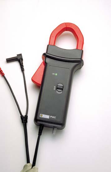
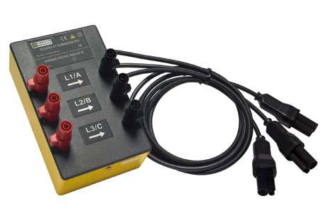
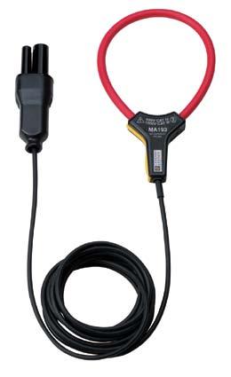
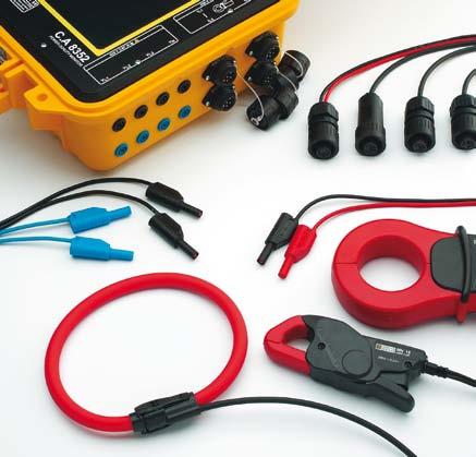
52 Portable, on-site and laboratory test and measurement instruments z 2010 catalogue Page z 87
Digital insulation tester
 Digital insulation tester C.A 6505 > > Insulation at 5 kv > > Wide measurement range from 10 kω to 10 TΩ > > Large backlit LCD screen, with digital display and bargraph > > Fixed test voltages and programmable
C.A 6117 C.A 6116N C.A 6113 Multi-function installation testers
 C.A 6117 C.A 6116N C.A 6113 Multi-function installation testers in Safety for your electrical installations, high performance of a unique instrument. 600 V CAT III Testing according to the international
Insulation Testers and Earth Ground Testers
 Insulation Testers and Earth Ground Testers With a 5000 V MegOhmMeter for industrial-strength insulation testing and a range of compact hand-held instruments, we offer a solution for every troubleshooting
Insulation Resistance Testing Guide
 50 to 5000 VDC Megohmmeters 2010 - Ed. 01 Insulation Resistance Testing Guide www.chauvin-arnoux.com Electrical insulation testing All electrical installations and equipment comply with insulation resistance
C.A 6115N. Safety at all costs. IEE 16th: Electrical installation IEC/EN I E C. Insulation RCD. Earth. Loop. Continuity.
 IEE 16th: Safety at all costs C.A 6115N Electrical installation Insulation RCD Earth Loop Continuity Phase rotation I E C CONFIRMS TO CONFIRMS TO IEC/EN 61557 1010-1 III 300V Cat Cat The most complete
Simple measurement at the best price
 Simple measurement at the best price n Multimeters n Clamp-on multimeters n Electrical safety testers n Testers n Environmental measurements n Laboratory instruments 01/2018 CONTENTS Multimeters page 3
MIT400/2 CAT IV Insulation testers
 MIT400/2 CAT IV Insulation testers MIT400/2 CAT IV Insulation testers Designed for Electrical and Industrial testing Insulation testing up to 1000 V and 200 GΩ range Stabilised insulation test voltage
MIT400/2. CAT IV Insulation testers MIT430/2: CAT IV Insulation testers
 MIT400/2 Designed for electrical and industrial testing Insulation testing up to 1000 V and 200 GΩ range Stabilized insulation test voltage (New) Single range, faster continuity testing from 0.01 Ω to
Clamp-on multimeters Multimeters Testers Electrical safety testers Environmental measurements Laboratory instruments 07/2018
 Simple measurement at the best price Clamp-on multimeters Multimeters Testers Electrical safety testers Environmental measurements Laboratory instruments 07/2018 Contents Clamp-on multimeters page 3 Multimeters
MIT400 CAT IV Industrial Insulation Testers
 MIT400 CAT IV MIT400 CAT IV CAT IV 600 V applications TRMS & DC Voltage measurement Insulation testing up to 1000 V and 200 GΩ Continuity testing at 200 ma or 20 ma down to 0.01 Ω Pass/Fail limit alarms
MIT400 CAT IV Industrial Insulation Testers
 MIT400 CAT IV MIT400 CAT IV CAT IV 600 V applications TRMS & DC Voltage measurement Insulation testing up to 1000 V and 200 GΩ Continuity testing at 200 ma or 20 ma down to 0.01 Ω Pass/Fail limit alarms
Testers: / Ohmmeters Insulation Measuring Instruments. n Compact and rugged for service calls and laboratory use. Scope of delivery:
 Table of Contents Testers: / Ohmmeters Insulation Measuring Instruments 51 METRAOHM 413 Article: M630A Digital Low-Resistance Measuring Instrument for Measuring Protective Conductors, Equipotential Bonding
MIT480/2 Insulation testers
 MIT480/2 Insulation testers MIT480/2 Insulation testers Insulation testing up to 500 V and 100 GΩ range in a hand held instrument 3 wire connection for A, B and E (Tip, Ring and Earth) connection (New)
The experience of the Qualistar ensuring high performance
 C.A 8332B C.A 8334B C.A 8335 The experience of the Qualistar ensuring high performance POWER AND ENERGY QUALITY ANALYSERS 3U IEC 61010 1000 V CAT III IEC 61010 600 V CAT IV 4V Measure all the necessary
Insulation resistance testing. A complete solution for every person.
 Insulation resistance testing. A complete solution for every person. Insulation resistance. The latest test tools from the testing experts. You asked. We responded. Now you have more insulation testing
MIT400/2 CAT IV Insulation testers
 MIT400/2 CAT IV Insulation testers MIT400/2 CAT IV Insulation testers Designed for Electrical and Industrial testing Insulation testing up to 1000 V and 200 GΩ range Stabilised insulation test voltage
MIT415 Insulation tester
 MIT415 Insulation tester General features o 10V & 100V ESD testing o 25V, 50V, 250V & 500V additional ranges o Insulation testing up to 50Gohms (500V) o Continuity testing at 200mA or 20mA from 0.01ohms
The future of installation testing is here. The Fluke 1650 Series Multifunction Testers
 The future of installation testing is here The Fluke 50 Series Multifunction Testers Fluke 50 Series Safer, easier installation testing. The 50 Series testers verify the safety of electrical installations
INDEX. Micro-ohmmeter MH-10 Page 3. MI (5, 10, 15, 20 kv) Page 4 Mega-ohmmeter MD (5 kv) Page 4
 Page 4 Mega-ohmmeter MD (5 kv) Page 4") Micro-ohmmeter MH-10 Page 3 MI (5, 10, 15, 20 kv) Page 4 Mega-ohmmeter MD (5 kv) Page 4 Earth resistance meter TL-5 Page 5 Indirect earth contact simulator MPC (5, 20, 50 A) Page 6 Trip time tester CR
Micro-ohmmeter MH-10 Page 3 MI (5, 10, 15, 20 kv) Page 4 Mega-ohmmeter MD (5 kv) Page 4 Earth resistance meter TL-5 Page 5 Indirect earth contact simulator MPC (5, 20, 50 A) Page 6 Trip time tester CR
MEGOHMMETER ENGLISH. User Manual
 MEGOHMMETER 5070 ENGLISH User Manual Statement of Compliance Chauvin Arnoux, Inc. d.b.a. AEMC Instruments certifies that this instrument has been calibrated using standards and instruments traceable to
C.A 6521 C.A 6523 C.A 6525
 MEGOHMMETRES MEGOHMMETERS MEGOHMMETER MEGAOHMMETRI MEGAÓHMETRO C.A 6521 C.A 6523 C.A 6525 FRANÇAIS ENGLISH DEUTSCH ITALIANO ESPANOL Notice de fonctionnement User's manual Bedienungsanleitung Libretto d
Testboy TV 416/432(A) CEE adapter*
 CEE adapter*") Testboy TV 416/432(A) CEE adapter* The Testboy TV 416/432(A) is a compact CEE adapter, comprising of a combination of CEE plug (16 A or 32 A), shockproof socket and self-closing flap cover, as well as
Testboy TV 416/432(A) CEE adapter* The Testboy TV 416/432(A) is a compact CEE adapter, comprising of a combination of CEE plug (16 A or 32 A), shockproof socket and self-closing flap cover, as well as
MIT400 CAT IV Industrial Insulation Testers
 MIT400 CAT IV Industrial Insulation Testers MIT400 CAT IV Industrial Insulation Testers CAT IV 600 V applications Insulation testing up to 1000 V and 200 GΩ Continuity testing at 200 ma or 20 ma down to
INSULATION TESTER SERIES
 INSULATION TESTER SERIES Field measuring instruments A Full Line-up of Insulation Testers to Suit Any Need From Basic Testing to High Performance Analysis 2 INSULATION TESTER SERIES Selection guide IR4056-20
MIT400 Series CAT IV Insulation Resistance and Continuity Testers
 Insulation testing up to 1000 V and 200 GΩ Patented analog arc and dual digital display CAT IV 600 V rating TRMS & DC Voltage measurement Continuity testing at 200 ma or 20 ma down to 0.01 Pass/Fail limit
Insulation resistance testing. A complete solution for every application
 Insulation resistance testing A complete solution for every application Insulation resistance The latest test tools from the testing experts You asked. We responded. Now you have more insulation testing
Contents. Measurement and checking equipment for transformation centers Micro-ohmmeter MH-10 Page 3. Indirect earth contact simulator TL-5 Page 5
 Measuring and testing equipments P 6 P.6.01 GB for substations Micro-ohmmeter MH-10 Page 3 Mega-ohmmeter MI (5, 10, 15, 20 kv) Page 4 MD (5 kv) Page 4 Indirect earth contact simulator TL-5 Page 5 Indirect
Electrical Test & Measurement Equipment
 Appliance Tester MI 3309 Delta GT Earth Bond Test 200 ma Insulation resistance (250 VDC, 500 VDC) Insulation resistance of isolated accessible conductive parts Substitute leakage current (up to 19.99mA
Fluke and
 Fluke 1623-2 and 1625-2 GEO Earth Ground Testers Technical Data The new Fluke 1623-2 and 1625-2 GEO Earth Ground Testers offer data storage and download capabilities via USB port. World class accessories
C.A User s manual MEGOHMMETER ENGLISH
 MEGOHMMETER C.A 6549 ENGLISH User s manual Thank you for purchasing a C.A. 6549 megohmmeter. To obtain the best service from your instrument: read this user manual carefully, comply with the precautions
GROUND TESTERS For all of your Ground Testing needs...
 GROUND TESTERS For all of your Ground Testing needs... An array of Ground Testers to choose from Whether you are doing a simplified 2-Point, a more complete 3- or 4-Point Fall-of-Potential test, a soil
10kV and 15kV MEGOHMMETERS 6550
 10kV and 15kV MEGOHMMETERS 6550 6555 ENGLISH User Manual Ships with the following: Megohmmeter Models 6550 / 6555 Cat. #2130.31 / Cat. #2130.32 PRODUCT PACKAGING Small Classic Tool Bag Cat. #2133.72 10kV
Insulation resistance testing. A complete solution for every application.
 Insulation resistance testing A complete solution for every application. Why perform insulation testing? Safety The most important reason for testing insulation is to ensure public and personal safety.
1650 Series Multifunction Installation Testers
 1650 Series Multifunction Installation Testers New RCD Type B Compatibility Extra functionality, faster testing, and as rugged as ever Fluke 1654B Fluke 1653B Fluke 1652C Safer, easier installation testing.
The experience of the Qualistar, ensuring high performance
 C.A 8332B C.A 8334B C.A 8335 C.A 8435 The experience of the Qualistar, ensuring high performance POWER AND ENERGY QUALITY ANALYSERS IEC 61010 1000 V CAT III 600 V CAT IV Measure all the necessary voltage,
INSULATION TESTER SERIES Selection guide
 INSULATION TESTER SERIES Selection guide Model IR4056 IR4057 IR4053 IR4016 to IR4018 3490 3455 Basic Specifications (Bar graph) Analog Meter IR4016 IR4017 IR4018 Analog Meter backlight function 3 3 3 3
MIT510/2, MIT520/2 and MIT1020/2
 MIT510/2, MIT520/2 and MIT1020/2 Line supply or battery operated Digital/analog backlit display Measurement range to 15 TΩ (MIT510/2 and MIT520/2) and 35 TΩ (MIT1020/2) CAT IV 600 V safety rating Automatic
BM25 Automated 5-kV Insulation Tester
 Insulation resistance measured to >5 TΩ Automated testing Polarization Index and Step Voltage tests Dielectric discharge test for multilayer insulation RS-232 download capability Weatherproof DESCRIPTION
Eurotest 61557, Instaltest 61557
 , Instaltest 61557, Instaltest 61557 Ultimate Instruments for Complete Testing of Electrical Installations Testing Measuring Analysing Recording No. 118740 VDE 0100 BS 7671 CEI 64.8 HD 384 EN 61557 VDE
NEW PRODUCT LAUNCH SALES GUIDE MIT480/2
 New NEW PRODUCT LAUNCH SALES GUIDE MIT480/2 Unique features Stabilised insulation testing 3 terminal connection Integral terminal switching Variable 10V to 500V test voltage Continuous continuity range
APPA 300 Series. The Most User-Friendly High Performance Multimeter
 APPA 300 Series The Most User-Friendly High Performance Multimeter Throw Away the Manual... So Easy, So Simple Straight Forward... For basic application, simply to operate these keys... "LIGHT" "BAR" "DIGIT"
GOSSEN METRAWATT. Testers
 Testers 45 Testers Protective measures in electrical systems are intended to prevent bodily injury due to accidents involving electrical current. Of course they also prevent property damage caused by electrical
FALL-OF-POTENTIAL GROUND RESISTANCE TESTER
 FALL-OF-POTENTIAL GROUND RESISTANCE TESTER Models 3620, 3640 & 4610 Call toll free (800) 537-0351 or visit www.allspec.com Measures soil resistivity (4-Point) (Model 4610) Measures ground resistance (2-
MEGOHMMETERS 10 kv AND 15 kv C.A 6550 C.A User s manual
 MEGOHMMETERS 10 kv AND 15 kv C.A 6550 C.A 6555 E N G L I S H User s manual Thank you for purchasing a megohmmeter C.A 6550 or C.A 6555. For best results from your instrument: read these operating instructions
METREL Measuring and Regulation Equipment
 METREL Measuring and Regulation Equipment ELECTRICAL INSTALLATION SAFETY MI 3108 EurotestPV MI 2230 VAFMeter MACHINES/APPLIANCES/SWITCHGEAR SAFETY A 1322 Active 3-phase Adapter MI 3310 SigmaGT HIGH VOLTAGE
Portable equipment for insulation fault location for unearthed and earthed systems (IT and TN systems) to be used in conjunction with or without an
 to be used in conjunction with or without an") EDS309 Portable equipment for insulation fault location for unearthed and earthed systems (IT and TN systems) to be used in conjunction with or without an equipment for insulation fault location EDS309x_D00012_02_D_XXEN/11.2018
EDS309 Portable equipment for insulation fault location for unearthed and earthed systems (IT and TN systems) to be used in conjunction with or without an equipment for insulation fault location EDS309x_D00012_02_D_XXEN/11.2018
C.A 8332 C.A Display your network analysis all in picture format! OBSERVE, DIAGNOSE, MONITOR... Three Phase Power Quality Analysers
 C.A 8332 C.A 8334 Display your network analysis all in picture format! OBSERVE, DIAGNOSE, MONITOR... Three Phase Power Quality Analysers Site ALSTOM POWER Service - Massy (France) Ready-to-use measurements
DM-III Multitest & DM-III Multitest F Power Quality Recorders
 DM-III Multitest & DM-III Multitest F Power Quality Recorders CAT 600V TRUE RMSz Amprobe s full-featured Three-Phase Power Quality Recorders provide the essential functions and capabilities required to
DM-III MULTITEST Power Quality Recorder
 DM-III MULTITEST Power Quality Recorder Amprobe s full-featured Three-Phase Power Quality Recorders provide the essential functions and capabilities required to operate accurately and effectively in today
5-kV and 10-kV Insulation Resistance Testers. n CAT IV 600 V safety rating. n Line supply or battery operated
 n CAT IV 600 V safety rating n Line supply or battery operated n Noise rejection (3mA or 4mA rms@200v and above) for use in high voltage substations or switchyards n 5mA output current provides fast charging
INSULATION TESTER SERIES. Flip the Cover. A Full Line-up of Insulation Testers to Suit Any Need. From Basic Testing to High Performance Analysis
 INSULATION TESTER SERIES Field measuring instruments A Full Line-up of Insulation Testers to Suit Any Need Flip the Cover From Basic Testing to High Performance Analysis 2 INSULATION TESTER SERIES Selection
Fluke 1623 and GEO Earth Ground Testers. Technical Data. Stakeless testing
 Fluke 1623 and 1625 GEO Earth Ground Testers Technical Data The new Fluke 1623 and 1625 GEO Earth Ground Testers offer an innovative solution, called Stakeless testing, to make your earth ground loop resistance
Installation Tester BENNING IT 115. Operating Manual
 Installation Tester BENNING IT 115 Operating Manual Manufacturer: BENNING Elektrotechnik und Elektronik GmbH & Co. KG Münsterstraße 135-137 D - 46397 Bocholt Phone: +49 (0) 2871-93 - 0 Fax: +49 (0) 2871-93
Portable equipment for insulation fault location for unearthed and earthed systems (IT and TN systems) to be used in conjunction with or without an
 to be used in conjunction with or without an") EDS309 Portable equipment for insulation fault location for unearthed and earthed systems (IT and TN systems) to be used in conjunction with or without an equipment for insulation fault location EDS309x_D00012_00_D_XXEN/05.2015
EDS309 Portable equipment for insulation fault location for unearthed and earthed systems (IT and TN systems) to be used in conjunction with or without an equipment for insulation fault location EDS309x_D00012_00_D_XXEN/05.2015
CATALOGUE PORTABLE TEST AND MEASUREMENT INSTRUMENTS
 CATALOGUE PORTABLE TEST AND MEASUREMENT INSTRUMENTS About the CHAUVIN ARNOUX GROUP Founded in Paris, France in 1893, CHAUVIN ARNOUX has spent the centuries since then developing its expertise in the design,
Current Clamp. 210
 Our range of devices includes clamp meters for measuring current leaks, AC and DC current, voltage, power, resistance, continuity, capacitance or frequency. Some clamp meters have a clearly arranged display
T/3000 T/3000. Substation Maintenance and Commissioning Test Equipment
 T/3000 Substation Maintenance and Commissioning Test Equipment MULTI FUNCTION SYSTEM FOR TESTING SUBSTATION EQUIPMENT SUCH AS: CURRENT, VOLTAGE AND POWER TRANSFORMERS, ALL TYPE OF PROTECTION RELAYS, ENERGY
DIGITAL ANALOG MEGOHMMETERS
 DIGITAL ANALOG MEGOHMMETERS 1035 1039 E N G L I S H User Manual Statement of Compliance Chauvin Arnoux, Inc. d.b.a. AEMC Instruments certifies that this instrument has been calibrated using standards and
Installation Tester BENNING IT 130. Operating Manual
 Installation Tester BENNING IT 130 Operating Manual Manufacturer: BENNING Elektrotechnik und Elektronik GmbH & Co. KG Münsterstraße 135-137 D - 46397 Bocholt Phone: +49 (0) 2871-93 - 0 Fax: +49 (0) 2871-93
METRAClip87 and 88 Clamp Multimeters
 3-349-795-03 1/7.14 Current and frequency measurement via clamp meter: METRAClip87: 1500 A AC TRMS and 1500 A DC METRAClip88: 2000 A AC TRMS and 3000 A DC Multimeter functions via connector sockets: V
C.A 6536 Megohmmeter
 GB - User s manual C.A 6536 Megohmmeter Thank you for purchasing a megohmmeter C.A 6536. For best results from your instrument: read these operating instructions carefully, comply with the precautions
The future of installation testing is here. The 1650 Series Multifunction Testers
 The future of installation testing is here The 50 Series Multifunction Testers 50 Series Safer, easier installation testing. Robin and Fluke joined forces in 999 to become the largest supplier of hand-held
MIT400 CAT IV Industrial Insulation Testers
 MIT400 CAT IV MIT400 CAT IV n CAT IV 600 V applications n TRMS & DC Voltage measurement n Insulation testing up to 1000 V and 200 GΩ n Continuity testing at 200 ma or 20 ma down to 0.01 Ω n Pass/Fail limit
HT FAMILY 400 METERS. Innovative meter designed to perform all safety test and power measurements on single phase system
 HT FAMILY 400 METERS Innovative meter designed to perform all safety test and power measurements on single phase system Description ISO410 Insulation / Continuity meter with remote probe GEO416 Professional
C.A 6532 C.A 6534 Megohmmeters
 GB - User s manual C.A 6532 C.A 6534 Megohmmeters Thank you for purchasing a megohmmeter C.A 6532 or C.A 6534. For best results from your instrument: read these operating instructions carefully, comply
The NEW itig II Winding and Motor Analyzer A revolution in automated, safe, and comprehensive high and low voltage tests all in a lightweight
 The NEW itig II Winding and Motor Analyzer A revolution in automated, safe, and comprehensive high and low voltage tests all in a lightweight package. The Electrom itig II offers a comprehensive range
MIT510, MIT520 and MIT1020
 MIT510, MIT520 and MIT1020 Line supply or battery operated Digital/analog backlit display Measurement range to 15 TΩ (MIT510 and MIT520) and 35 TΩ (MIT1020) Automatic insulation resistance tests Automatic
BMM80 Premium Insulation Multimeters
 Insulation measurement to 200 GΩ 200 ma Short Circuit Current output mv Transducer inputs Test lead/transducer null facility Backlight Remote control switched probe included Capacitance Measurement to
NEO TELE-TRONIX PVT. LTD. 6/7 Bijoygarh, Kolkata , Tel : ; Fax :
 NEO TELE-TRONIX PVT. LTD. 6/7 Bijoygarh, Kolkata - 700 032, Tel : 033 2477 3126; Fax : 033 2477 2403 www.ntplindia.com SPECIFICATION NTPL MAKE MICRO-CONTROLLER BASED AUTOMATIC 50KV/10A AC HIGH VOLTAGE
MEGOHMMETER C.A User's manual
 MEGOHMMETER C.A 6549 E N G L I S H User's manual 1 Meaning of symbol CAUTION! Refer to the user manual before using the instrument. Failure to follow or carry out the instructions in this User Manual preceded
THE ELECTROM itig II MOTOR TESTER AND WINDING ANALYZER
 THE ELECTROM itig II MOTOR TESTER AND WINDING ANALYZER AUTOMATED, SAFE, AND EASY TO USE TESTER. HIGH AND LOW VOLTAGE TESTS IN A LIGHTWEIGHT PACKAGE. The state of the art Electrom itig II provides a wide
C.A Complete electrical network analysis at the tips of your fingers! Power Quality Monitor. Keeping up with the standards
 Keeping up with the standards C.A 8352 Power Quality Monitor Complete electrical network analysis at the tips of your fingers! All measurements for complete analysis: powers, harmonics, flicker, symmetry,
Megohmmeter Model 1060
 CHAUVIN ARNOUX GROUP Chauvin Arnoux Inc. 15 Faraday Drive Dover, NH 03820 USA (603) 749-6434 Fax (603) 742-2346 www.aemc.com Issue 13 WATTS CURRENT TECHNICAL BULLETIN Summer/Fall 2017 Megohmmeter Model
Top-Innovator MotorAnalyzer 2. Multi-purpose testers for electric motors and windings. Made in Germany Expect more.
 Top-Innovator 2014 MotorAnalyzer 2 Multi-purpose testers for electric motors and windings Made in Germany Expect more. EN Winding testers 1 The MotorAnalyzer 2 unbeatably versatile The all-purpose MotorAnalyzer
Top-Innovator MotorAnalyzer 1. Multi-purpose testers for electric motors and windings. Made in Germany Expect more.
 Top-Innovator 2014 MotorAnalyzer 1 Multi-purpose testers for electric motors and windings Made in Germany Expect more. EN Winding testers 1 The MotorAnalyzer 1 the multi-purpose tool The MotorAnalyzer
1650 Series Multifunction Installation Testers
 1650 Series Multifunction Installation Testers Fluke 1654B Fluke 1653B Fluke 1652C BS7671 17th Edition IEE Wiring Regulations IEC 60364.6.61, HD 384 6 AA Cell batteries C1600 Hard carrying case Zero Adapter
Instruction Manual for Digital Grounding Resistance Meter
 Instruction Manual for Digital Grounding Resistance Meter Instruction Manual for Digital Grounding Resistance Meter Table of Contents I. Overview...2 II. Open-case Inspection...3 III. Safety Precautions...4
Instruction Manual for Digital Grounding Resistance Meter. Table of Contents
 I. Overview...2 II. Open-case Inspection...3 III. Safety Precautions...4 IV. Work Principle...7 V. Appearance Description...9 VI. Technical Characteristics 10 VII. Resistance Measurement Method..12 VIII.Battery
C.A 8332 C.A Advanced Test Equipment Rentals ATEC (2832) Display your network analysis all in picture format!
 Display your network analysis all in picture format!") Established 1981 Advanced Test Equipment Rentals www.atecorp.com 800-404-ATEC (282) Display your network analysis all in picture format! OBSERVE, DIAGNOSE, MONITOR... C.A 82 C.A 84 Three Phase Power Quality
Established 1981 Advanced Test Equipment Rentals www.atecorp.com 800-404-ATEC (282) Display your network analysis all in picture format! OBSERVE, DIAGNOSE, MONITOR... C.A 82 C.A 84 Three Phase Power Quality
DVM645BI BENCH MULTIMETER TAFELMULTIMETER MULTIMETRE DE TABLE BANCO MULTÍMETRO TISCHMULTIMETER. User Manual. Gebruikershandleiding
 BENCH MULTIMETER TAFELMULTIMETER MULTIMETRE DE TABLE BANCO MULTÍMETRO TISCHMULTIMETER User Manual Gebruikershandleiding Manuel d'utilisation Gebrauchsanleitung Introduction BENCH MULTIMETER This manual
International distributors
 International distributors MADE IN USA Smart hipot Smart DC hipot up to 60 kv HP60KV Can be fully remote-controlled from an Android device Output voltage up to 60 kv DC Leakage current up to 6 ma Can be
HT COMBI419. Innovative meter designed to perform all safety test
 HT COMBI419 Innovative meter designed to perform all safety test Description COMBI419 and COMBI420 is an innovative meter designed to perform all safety test verifies on electrical installations in compliance
C a t a l o g u e
 2 0 1 0 C a t a l o g u e European Leader in Measurement The Chauvin Arnoux Group, the European leader in the measurement sector, now proposes a comprehensive product offering in the field of measurement
1587/1577. Insulation Multimeters. Technical Data. Two powerful tools in one.
 Test Equipment Depot - 800.517.8431-99 Washington Street Melrose, MA 02176 - TestEquipmentDepot.com 1587/1577 Insulation Multimeters Technical Data Two powerful tools in one. The Fluke 1587 and 1577 Insulation
Pince Multimètre - Courants de fuites Leakage Clamp-on Meter Multimeter und Fehlerstrom-Messzange Pinza Multimetro - Correnti di fuga
 Pince Multimètre - Courants de fuites Leakage Clamp-on Meter Multimeter und Fehlerstrom-Messzange Pinza Multimetro - Correnti di fuga Pinza Multímetro - Corrientes de fugas F 62 F 65 FRANÇAIS ENGLISH DEUTSCH
Multifunction AC/DC Voltage Tester
 User Manual Multifunction AC/DC Voltage Tester Model 20250-59 THE STANDARD IN PRECISION MEASUREMENT 1065DGMAN_20250-59 DS multifunctional voltage tester.indd 1 8/8/2017 1:37:47 PM Introduction The Digi-Sense
EurotestEASI MI 3100 SE MI 3100 s Instruction manual Version 1.1, Code no
 EurotestEASI MI 3100 SE MI 3100 s Instruction manual Version 1.1, Code no. 20 752 131 Distributor: Manufacturer: METREL d.d. Ljubljanska cesta 77 1354 Horjul Slovenia web site: http://www.metrel.si e-mail:
Multi-Function Installation Tester MEGGER CM500. User Guide MEGGER
 Multi-Function Installation Tester MEGGER CM500 User Guide MEGGER Contents Safety Warnings 3 Initial Setup 4 General Description 6 Features, Controls and Connections 8 Operation 10 Backlight 10 Auto shut-off
GAMMA 10 DIGITAL MULTIMETER
 Gamma 10 www.sifamtinsley.co.uk DATASHEET Issue 1.0 Multifunction Meters Transducers & Isolators Temperature Controllers Converters & Recorders Digital Panel Meters Current Transformers Analogue Panel
MACROTEST G1 & G2. I'm pure technology. Touch me, please.
 MACROTEST G1 & G2 I'm pure technology. Touch me, please. 5 Clear answer. Complying o not. Save time! You will take half time! Color Touch Screen with icon intuitive graphics Wi-Fi and USB Power measurement
MEGGER CM300 MK II, CM400 MK II & CM500
 MEGGER CM300 MK II, CM400 MK II & CM500 Multi-Function Installation Testers User Guide MEGGER Contents Safety Warnings 3 Initial Setup 4 General Description 6 Features, Controls and Connections 8 Operation
G SAFETY WARNINGS. LT300 High current loop tester. User guide
 M LT300 High current loop tester User guide G SAFETY WARNINGS Safety Warnings and Precautions must be read and understood before the instrument is used. They must be observed during use. The earth loop
10/2 Product overview. 10/3 4AC3 0, 4AC3 1 bell transformers. 10/5 4AC AC3 6 transformers for permanent loads. 10/8 4AC2 4 power supply units
 BETA Switching Transformers, Bells and Socket Outlets /2 Product overview /3 4AC3 0, 4AC3 1 bell transformers /5 4AC3 4... 4AC3 transformers for permanent loads /8 4AC2 4 power supply units / 7LQ2 2 bells
EurotestXE MI 3102H BT, MI 3102 BT Instruction manual Version 1.0, Code no
 EurotestXE MI 3102H BT, MI 3102 BT Instruction manual Version 1.0, Code no. 20 752 160 Distributor: Manufacturer: METREL d.d. Ljubljanska cesta 77 1354 Horjul Slovenia web site: http://www.metrel.si e-mail:
GAMMA 12 DIGITAL MULTIMETER
 Gamma 12 www.sifamtinsley.co.uk DATASHEET Issue 1.0 Multifunction Meters Transducers & Isolators Temperature Controllers Converters & Recorders Digital Panel Meters Current Transformers Analogue Panel
EurotestCOMBO MI 3125 / MI 3125E Short instructions Version 2.2, Code no
 EurotestCOMBO MI 3125 / MI 3125E Short instructions Version 2.2, Code no. 20 751 519 Distributor: Manufacturer: METREL d.d. Ljubljanska cesta 77 1354 Horjul Slovenia web site: http://www.metrel.si e-mail:
ELECTRICAL SAFETY TESTERS. Wings for Your Projects. APPLICATION NOTE
 APPLICATION NOTE ELECTRICAL SAFETY TESTERS Wings for Your Projects. Four Principal Tests for Evaluating the Safety of Electrical and Electronic Products TOS SERIES ELECTRICAL SAFETY TESTER TOS SERIES SELECTION
Family 400 meters Rel /04/2007
 COMBI49 COMBI420 ISO40 SPEED48 Pag - 6. MAIN FEATURES OF FAMILY 400 METERS Help on line (available on each function) to support the user while connecting the instrument to the installation under measurement
SDM3045X Digital Multimeter. DataSheet
 SDM3045X Digital Multimeter DataSheet-2016.06 User-friendly Design Product Overview SDM3045X is a 4½ digit digital (60000 count) multimeter incorporating a dual-display and is especially well suited for
GROUND RESISTANCE TESTERS
 GROUND RESISTANCE TESTERS For all of your Ground Integrity Testing needs... An array of Ground Resistance Testers to choose from... Whether you are doing a simplified 2-Point, a more complete - or 4-Point