The Nautel Difference
|
|
|
- Godfrey Cook
- 6 years ago
- Views:
Transcription
1 The Nautel Difference NAUTEL HAS A LONG HISTORY AND THE RESOURCES TO DELIVER THE BEST SOLUTION Founded in 1969 Over 11,000 systems shipped Systems installed in 177 countries Over 200 employees More than 40 engineers on staff Manufacturing facilities in The United States of America and Canada NAUTEL HAS THE BEST CUSTOMER SERVICE AND POST-PURCHASE SUPPORT Emergency technical support is available 24 hours a day, 7 days a week. Nautel training programs provide the support you need. 3-day product specific training programs and a 5-day RF basics training program are available. A next day module exchange program is available in Canada and the US. Nautel s first priority is getting customers back on the air, even if the model in question was purchased in NAUTEL HAS SIGNIFICANT TECHNICAL DEPTH AND MANUFACTURING EXPERTISE The Vector series is wholly Nautel designed and manufactured. Our manufacturing and design facilities are registered by International Quality System Registrars to ISO 9001:2008 Nautel s broad product portfolio means we have a large technical pool for product design and product support. In-house design skills: Solid state amplifier design from 100 khz to 100 MHz Antennas Analog and digital communications theory RF matching, combining and filtering at high power and high voltages RF magnetics Power supplies Digital hardware design Digital signal processing Data communications systems Networking and TCP development Design, manufacture and support of high power, high reliability Radio Frequency ( RF ) systems: Medium wave AM & FM broadcast transmitters (analog & digital) Navigational radio beacons Differential Global Positioning System (DGPS) transmitters Medium Frequency (MF) Telegraph and Navtex Communications High Frequency (HF) Amplifiers for industrial RF applications Next Generation LORAN (Long Range Navigation) transmitters VHF FM Weather Radio Transmitters LF Sonar amplifiers NAVIGATION PRODUCTS AVAILABLE FROM NAUTEL Low, medium and high power non directional radio beacon and DGPS transmitters LF/MF transmitting antennas including heli-deck, whip, self supporting mast and horizontal T LF/MF automatic antenna tuning units MF telegraph and navtex transmitters for shore based installations Remote control/monitor units and remote control/ monitor software applications Beacon monitor receiver Battery chargers

2 For further information, please contact us at: Nautel Limited ISO9001 Registered Peggy s Cove Road Hackett s Cove, Nova Scotia Canada B3Z 3J4 Phone: Nautel Inc. ISO9001 Registered 201 Target Industrial Circle Bangor, Maine USA Fax: navaids@nautel.com Nautel installed Beacon transmitters Online access to Nautel s restricted NUG (Beacon Users Group) website: UNLOCK A WORLD OF INFORMATION. JOIN THE NUG. Membership in the Beacon Users Group is an excellent way to receive technical content, education and information on the Nautel platforms, products, and technologies that you are interested in. Technical FAQs Technical manuals Information sheets Field upgrade documents Special NUG discounts on select Nautel training programs If you would like to become a NUG member you can register online by visiting our website at Issue 1.2, February 20, 2012

3 Nautel Vector Series


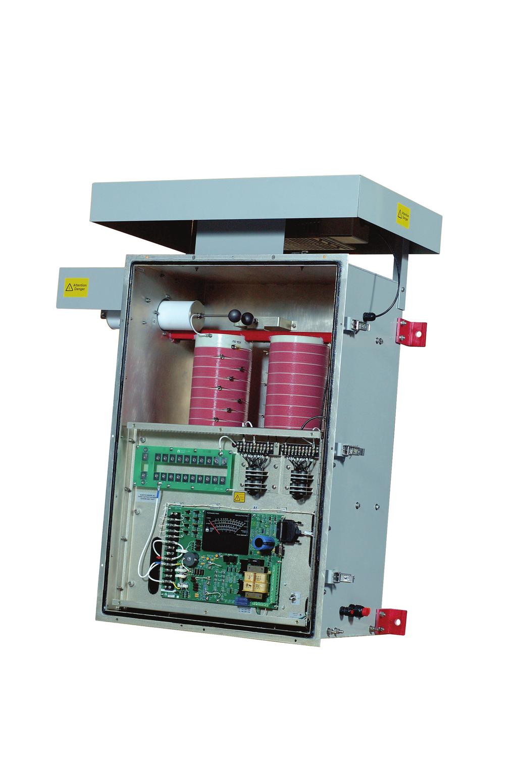
4 Nautel Vector Series ATU-HP Antenna Tuning Unit ATU-LP Antenna Tuning Unit ATU-500SR Antenna Tuning Unit INTR O DU CI NG N AU T E L S N E W V E C TOR S E R I ES OF NDB TR A NSMI T T E R S AN D AT Us Since introducing the world s first totally solid state, high power radio-beacon in 1970, Nautel has supplied the highest quality and reliability in non-directional radio beacons. The new Vector Series Transmitters and Antenna Tuning Units continue this heritage and provide a dramatic improvement in system coverage. The Vector series utilizes all of Nautel s 40 plus years of experience with beacons and adds must have features including: Constant field strength output for higher system availability.* Automatic resistance matching for higher system availability.* Remote control of the ATU to limit worker exposure to strong RF fields, in keeping with Safety Code 6 / IEEE C Sophisticated graphic user interface (GUI) for easy maintenance and troubleshooting. Extensive automatic fault monitoring for faster troubleshooting. Extensive remote command and control capabilities for fewer site visits. The Vector Series offers a unique solution (patent pending) to maintain system coverage regardless of undesirable antenna effects.* *Features not available on ATU-500SR


5 THE PROBLEMS Antennas used for navigational aids are usually small and inefficient, for both practical and economic reasons. This results in the following undesirable antenna characteristics: Low antenna system efficiencies are common. ATU loading coil resistance can cause significant system losses. High ratio of reactance to resistance creates a narrow band filter effect which can attenuate the sidebands of the radiated signal. Automatic tuning of the loading coil is necessary to offset small changes of antenna capacitance to keep the antenna ON TUNE with changing conditions. Resistive changes in ground plane and insulator losses can cause increased reflected power and a reduction of forward power at the transmitter. The transmitter may reduce power or even shut down, to prevent equipment damage. Manual adjustments to the ATU matching transformer are often needed as weather conditions change to offset resistive changes, necessitating expensive field maintenance trips. Even if a perfect match is obtained, changes of the antenna loss resistance cause changes of antenna efficiency with a resulting change of coverage. NAUTEL S SOLUTION A new technique provides automatic operation of both the loading coil tuning and adjustment of a resistive matching network in the ATU such that a near perfect match is maintained keeping the antenna tuned and its resistance matched under changing conditions. A serial data link between the ATU and the Vector transmitter stabilizes the antenna current, and the radiated power, by automatically adjusting the transmitter output power. A 2:1 change of the total antenna resistance requires an associated 2:1 change of transmitter time+power to maintain a constant antenna current. The transmitter must have a suitable maximum power rating to realize the complete benefits of this solution. The Nautel solution offers confidence that consistent system coverage is achieved. Loading coil losses are Vector NDB Low Power reduced, improving antenna system efficiency. An optional resistor bank for the ATU adds additional resistance in series with the antenna, optimizing the trade-off between antenna bandwidth and efficiency. Vector NDB High Power
6 NAUTEL VECTOR REMOTE CONTROL/MONITORING Nautel s latest generation of Non-Directional Radio Beacons (Vector) includes the resources for remote monitoring and control. The Vector NDB includes serial interfaces that allow a remote PC to control and monitor the Vector system including the Antenna Tuning Unit via the VR-Link remote control/monitoring. Nautel s VR-Link Vector remote control/monitor provides password protected access to control and monitor the Vector system. When connected, the user has access to the vast array of control, status and alarms that are available with the Vector system. Functions such as maintenance checks, system status checks, and system troubleshooting to the lowest replaceable unit (LRU) are all available from the remote PC. Fig. 1: Vector NDB & VR-Link2 Interconnect Options (VR-Link2 Installed at Remote Location) Integrated ECMP (Optional) RS232 15m Max RS485 1km Max ECMP (Optional) PC (Not Supplied) VR-Link2 Fig. 2: Vector NDB & VR-Link2 Interconnect Options (VR-Link2 Co-located with Vector NDB) OR OR OR OR RS422 1km Max Leased Line RS232 RS232 Vector NDB Network Remote PC (Not Supplied) AND/OR AND/OR Local PC (Not Supplied) VR-Link2 Vector NDB
Nautel Land-based NDB Systems. Gary Galbraith, P.Eng. Technical Sales Representative, Navigational Products
 Nautel Land-based NDB Systems Gary Galbraith, P.Eng. Technical Sales Representative, Navigational Products Corporate History Design, manufacture, sales and support of 3 product lines Navigational Products
High power, digitally controlled, efficient, RF designs and solutions. Introduction to Nautel and NS Series LF High Power Amplifier
 High power, digitally controlled, efficient, RF designs and solutions Introduction to Nautel and NS Series LF High Power Amplifier SONAR Applications About Nautel 42 Years 250 employees 40 designers/engineers
NA100 NA200 NA300. NA Series Frequency Agile Medium Wave Broadcast Transmitters
 NA100 NA200 NA300 NA Series Frequency Agile Medium Wave Broadcast Transmitters Making Digital Radio Work. Nautel NA100, NA200 & NA300 Quick Specs Field tunable to any frequency in the medium wave band
Nautel NDB Systems for the. Gary Galbraith, P.Eng. Technical Sales Representative, Navigational Products
 Nautel NDB Systems for the Offshore Market Gary Galbraith, P.Eng. Technical Sales Representative, Navigational Products Corporate History Design, manufacture, sales and support of 3 product lines Navigational
1 KW TOTALLY SOLID STATE DIFFERENTIAL GPS TRANSMITTER ( khz)
") GPS1000 1 KW TOTALLY SOLID STATE DIFFERENTIAL GPS TRANSMITTER (282-326 khz) NAUTEL has developed the GPS1000 as an extremely efficient and highly reliable transmitter especially suited for use at remote
GPS1000 1 KW TOTALLY SOLID STATE DIFFERENTIAL GPS TRANSMITTER (282-326 khz) NAUTEL has developed the GPS1000 as an extremely efficient and highly reliable transmitter especially suited for use at remote
Comparison of a Southern Avionics Diamond Portable Antenna with a New Design Proposed by Nautel
 Comparison of a Southern Avionics Diamond Portable Antenna with a New Design Proposed by Nautel John Pinks Chief Engineer Emeritus January 2004 Nautel Limited 10089 Peggy's Cove Road, Hackett's Cove, NS,
XR kw AM Medium Wave Broadcast Transmitter
 XR12 12 kw AM Medium Wave Broadcast Transmitter Ready for digital. Ready for anything. Nautel XR12 Quick Specs RF Output Power 12 kw (rated) 15 kw (capable) 145% positive peak modulation at 12 kw 1.5:1
Digital/Analog Transmitter NX50. 50kW AM. Digital/Analog AM
 NX50 Digital/Analog AM 50kW AM Digital/Analog Transmitter NX50 The NX50 sets a new standard for digital performance, rugged design and operational ease in the industry s most compact enclosure. Add AM
NXSeries. Digital/Analog MW. 50kW-2,000kW Digital/Analog Medium Wave Transmitters
 NXSeries Digital/Analog MW 50kW-2,000kW Digital/Analog Medium Wave Transmitters NX Series The new power in medium wave. 50kW- 2MW NX300, 300kW MW Transmitter With power outputs of 50 to 2,000 kw, the NX
J kw AM Transmitter
 J1000 1 kw AM Transmitter J1000 1 kw AM Transmitter J1000 1kW AM Transmitter GREAT THINGS REALLY DO COME IN SMALL PACKAGES. The J1000 transmitter provides excellent functionality and flexibility for the
Installing a COMROD AS1R Whip Antenna with Anchor Post
 Installing a COMROD AS1R Whip Antenna with Anchor Post IS10012 Issue 1.0...15 September 2010 Nautel Limited 10089 Peggy's Cove Road, Hackett's Cove, NS, Canada B3Z 3J4 T.877 6 nautel (628835) or +1.902.823.2233
Banska Bystrica Branch. NDB + Marker NARASYS (Navigation Radio-Beacon System)
") Banska Bystrica Branch NDB + Marker (Navigation Radio-Beacon System) JB 2014 3 System consists of Modules: Non-Directional Dual Radio-Beacon (NDB) NAVYRA-M - Artificial Loud incl. VHF Position Marker RM-01C
Banska Bystrica Branch NDB + Marker (Navigation Radio-Beacon System) JB 2014 3 System consists of Modules: Non-Directional Dual Radio-Beacon (NDB) NAVYRA-M - Artificial Loud incl. VHF Position Marker RM-01C
Changing NE IBOC Service Mode
 Changing NE IBOC Service Mode IS06001 Issue 1.1... 30 March 2006 Nautel Limited 10089 Peggy's Cove Road, Hackett's Cove, NS, Canada B3Z 3J4 T.+1.902.823.2233 F.+1.902.823.3183 info@nautel.com U.S. customers
PRINCIPLES OF COMMUNICATION SYSTEMS. Lecture 1- Introduction Elements, Modulation, Demodulation, Frequency Spectrum
 PRINCIPLES OF COMMUNICATION SYSTEMS Lecture 1- Introduction Elements, Modulation, Demodulation, Frequency Spectrum Topic covered Introduction to subject Elements of Communication system Modulation General
COMM 704: Communication Systems
 COMM 704: Communication Lecture 1: Introduction Dr. Mohamed Abd El Ghany, Mohamed.abdel-ghany@guc.edu.eg Course Objective Give an introduction to the basic concepts of electronic communication systems
Technician License Course Chapter 4. Lesson Plan Module 9 Antenna Fundamentals, Feed Lines & SWR
 Technician License Course Chapter 4 Lesson Plan Module 9 Antenna Fundamentals, Feed Lines & SWR The Antenna System Antenna: Transforms current into radio waves (transmit) and vice versa (receive). Feed
Technician License Course Chapter 3 Types of Radios and Radio Circuits. Module 7
 Technician License Course Chapter 3 Types of Radios and Radio Circuits Module 7 Radio Block Diagrams Radio Circuits can be shown as functional blocks connected together. Knowing the description of common
XR12. Frequency Change Procedure IS Issue August 2007
 XR12 Frequency Change Procedure IS07013 Issue 1.0... 31 August 2007 Nautel Limited 10089 Peggy's Cove Road, Hackett's Cove, NS, Canada B3Z 3J4 T.877 6 nautel (628835) or +1.902.823.2233 F.+1.902.823.3183
ATTACHMENT E. How to Conduct a GMDSS Inspection.
 Page 1 of 7 NOTE: This document is an excerpt from The Report and Order In the Matter of Amendment of the Commission's Rules Concerning the Inspection of Radio Installations on Large Cargo and Small Passenger
DOPPLER VHF OMNIDIRECTIONAL RANGE
 Supplying ATM systems around the world for more than 30 years Characteristics MONITOR Single/dual Monitor voting And/or Alarm thresholds User configurable Carrier power 3 db (digitally adjustable) Bearing
1. SYSTEM DESCRIPTION NON - DIRECTIONAL RADIO BEACON TRANSMITTER (NDB) JTM-30C
 JTM-30C") Documentation Rev.Date Rev. Document no. 1. SYSTEM DESCRIPTION NON - DIRECTIONAL RADIO BEACON TRANSMITTER (NDB) JTM-30C 1. SYSTEM DESCRIPTION... 2 1.1 OVERALL SYSTEM DESCRIPTION... 2 1.2 BASIC MODULES...
Documentation Rev.Date Rev. Document no. 1. SYSTEM DESCRIPTION NON - DIRECTIONAL RADIO BEACON TRANSMITTER (NDB) JTM-30C 1. SYSTEM DESCRIPTION... 2 1.1 OVERALL SYSTEM DESCRIPTION... 2 1.2 BASIC MODULES...
XR kw AM Medium Wave Broadcast Transmitter
 XR12 12 kw AM Medium Wave Broadcast Transmitter XR12 12 kw AM Medium Wave Broadcast Transmitter XR Series Power Module POWERFUL BUILDING BLOCKS The building block for the XR12 is a power module integrating
REVISED QUESTIONNAIRE ON SHORE-BASED FACILITIES FOR THE GLOBAL MARITIME DISTRESS AND SAFETY SYSTEM (GMDSS)
") E 4 ALBERT EMBANKMENT LONDON SE1 7SR Telephone: +44 (0)20 7735 7611 Fax: +44 (0)20 7587 3210 MSC.1/Circ.1382/Rev.2 24 June 2013 REVISED QUESTIONNAIRE ON SHORE-BASED FACILITIES FOR THE GLOBAL MARITIME DISTRESS
E 4 ALBERT EMBANKMENT LONDON SE1 7SR Telephone: +44 (0)20 7735 7611 Fax: +44 (0)20 7587 3210 MSC.1/Circ.1382/Rev.2 24 June 2013 REVISED QUESTIONNAIRE ON SHORE-BASED FACILITIES FOR THE GLOBAL MARITIME DISTRESS
Base Station Installation and Maintenance
 Base Station Installation and Maintenance Leading the wireless revolution is not an easy task. Ensuring that your base stations are installed at an optimal level of efficiency and maintained according
CHAPTER - 6 PIN DIODE CONTROL CIRCUITS FOR WIRELESS COMMUNICATIONS SYSTEMS
 CHAPTER - 6 PIN DIODE CONTROL CIRCUITS FOR WIRELESS COMMUNICATIONS SYSTEMS 2 NOTES 3 INTRODUCTION PIN DIODE CONTROL CIRCUITS FOR WIRELESS COMMUNICATIONS SYSTEMS Chapter 6 discusses PIN Control Circuits
Cell Extender Antenna System Design Guide Lines
 Cell Extender Antenna System Design Guide Lines 1. General The design of an Antenna system for a Cell Extender site needs to take into account the following specific factors: a) The systems input and output
Southern Avionics Company
 Southern Avionics Company Transportable NDB System Part Number: SLF33800 SHEET 5055 Belmont, Beaumont, TX 77707 Phone +409.842.1717/1.800.648.6158 (Toll Free in the US) Fax +409.842.2987 sales@southernavionics.com
Global Maritime Distress and Safety System (GMDSS)
") Global Maritime Distress and Safety System (GMDSS) Global Maritime Distress and Safety System (GMDSS) BACKGROUNG, APPLICATION, DEFINITION GMDSS (Background) SOLAS 74 Ships 1600 TRG Radio Installation Ships
Global Maritime Distress and Safety System (GMDSS) Global Maritime Distress and Safety System (GMDSS) BACKGROUNG, APPLICATION, DEFINITION GMDSS (Background) SOLAS 74 Ships 1600 TRG Radio Installation Ships
Agilent 8360B/8360L Series Synthesized Swept Signal/CW Generators 10 MHz to 110 GHz
 Agilent 8360B/8360L Series Synthesized Swept Signal/CW Generators 10 MHz to 110 GHz ity. l i t a ers V. n isio c e r P. y t i l i ib Flex 2 Agilent 8360 Synthesized Swept Signal and CW Generator Family
VLF-LF-MF Up Converter
 VLF-LF-MF Up Converter 5kHz-500kHz 3.5MHz-4MHz model 350 4MHz-4.5MHz model 400 User manual. Rev 2018-01 Since many countries are allocating the 472 khz to 479kHZ band for experimental use by Radio Amateurs,
A Technical Report: Jampro s Dual Input Interleaved HD FM antenna:
 A Technical Report: Jampro s Dual Input Interleaved HD FM antenna: This JMPC-2 + JMPC-2-HD is shown installed on a 24 triangle tower. Many other configurations are available to meet your HD Radio Needs.
GMDSS RADIO INSTALLATION
 Ship s name: N.R. Survey: GMDSS RADIO INSTALLATION (Res. A.1053(27)) INITIAL (Newconstruction) PERIODICAL RENEWAL Sea areas: A1 Methods of maintenance: Duplication of (Reg. IV/12-15) A1+A2 (Reg. IV/15)
Definitions of Technical Terms
 Definitions of Technical Terms Terms Ammeter Amperes, Amps Band Capacitor Carrier Squelch Diode Dipole Definitions How is an ammeter usually connected = In series with the circuit What instrument is used
TK-2312E TK-3312E. New Product Release Information. VHF FM Transceiver UHF FM Transceiver. March 2011
 New Product Release Information TK-2312E TK-3312E VHF FM Transceiver UHF FM Transceiver March 2011 We are pleased to send you product information on our new VHF and UHF FM Portable Transceivers, the TK-2312E
UNIT 1 QUESTIONS WITH ANSWERS
 UNIT 1 QUESTIONS WITH ANSWERS 1. Define modulation? Modulation is a process by which some characteristics of high frequency carrier signal is varied in accordance with the instantaneous value of the modulating
AUDIO SYSTEM DESCRIPTION
 BE86 DESCRIPTION 1. RADIO WAVE BAND BE0AX03 The radio wave bands used in radio broadcasting are as follows: Frequency Designation 30 khz 300 khz 3 MHz 30 MHz 300 MHz LF MF HF VHF Radio wave FM Modulation
VLF-LF Up Converter 5KHz - 500KHz. User manual. Rev HEROS technology Limited All rights reserved
 VLF-LF Up Converter 5KHz - 500KHz User manual. Rev 2016-02 Since many countries are allocating the 472 khz to 479kHZ band for experimental use by Radio Amateurs, a growing number of them as well as listeners
Vector. Radio Beacon Transmitter. Technical Instruction Manual VR500 VR1000 VR2000. Issue June 2009
 Vector Radio Beacon Transmitter Technical Instruction Manual VR500 VR1000 VR2000 Issue 2.0... 05 June 2009 Nautel Limited 10089 Peggy's Cove Road, Hackett's Cove, NS, Canada B3Z 3J4 T.877 6 nautel (628835)
Introduction to: Radio Navigational Aids
 Introduction to: Radio Navigational Aids 1 Lecture Topics Basic Principles Radio Directional Finding (RDF) Radio Beacons Distance Measuring Equipment (DME) Instrument Landing System (ILS) Microwave Landing
RFID Frequency Overview to Application fit
 RFID Frequency Overview to Application fit 1 The Radio Spectrum RFID tags exhibit different characteristics at different frequencies and it is highly unlikely that there will ever be one tag that can be
Chapter 1: Telecommunication Fundamentals
 Chapter 1: Telecommunication Fundamentals Block Diagram of a communication system Noise n(t) m(t) Information (base-band signal) Signal Processing Carrier Circuits s(t) Transmission Medium r(t) Signal
R40 Mk III AIS Base Station
 R40 Mk III AIS Base Station The new R40 Mk III AIS Base Station from Saab TransponderTech is a result of our on-going efforts to enhance all our products. The R40 Mk III is equipped with a new Base Station
Physics of RFID. Pawel Waszczur McMaster RFID Applications Lab McMaster University
 1 Physics of RFID Pawel Waszczur McMaster RFID Applications Lab McMaster University 2 Agenda Radio Waves Active vs. Passive Near field vs. Far field Behavior of UHF fields Modulation & Signal Coding 3
Analog signal generator that meets virtually every requirement
 GENERAL PURPOSE 44434/5 FIG 1 The R&S SMA1A offers excellent performance and compact design at a favorable price. Signal Generator R&S SMA1A Analog signal generator that meets virtually every requirement
Nautel Limited FM 3.5 kw, 5 kw, 8 kw Totally Solid State FM Broadcast Transmitters
 RUGGED SOLID STATE MODULAR DESIGN No tubes to replace No routine tuning or adjustments 65% typical overall efficiency NAUTEL PATENTED COMBINING TECHNIQUE Failure isolation between PA's Multiple power amplifier
Power Monitoring in Multicarrier systems
 Power Monitoring in Multicarrier systems It is the responsibility of the engineer to fully understand the hardware used in their design and reduce the risk of not delivering the requirements included in
RECOMMENDATION ITU-R F Characteristics of HF fixed radiocommunication systems
 Rec. ITU-R F.1761 1 RECOMMENDATION ITU-R F.1761 Characteristics of HF fixed radiocommunication systems (Question ITU-R 158/9) (2006) Scope This Recommendation specifies the typical RF characteristics of
Review: The MFJ-223 Vector Impedance Antenna Analyzer Phil Salas AD5X
 Review: The Vector Impedance Antenna Analyzer Phil Salas AD5X The is MFJ s latest entry in the antenna analyzer market. Its TFT multi-color display provides a large amount of information on a very compact
AIRCRAFT AVIONIC SYSTEMS
 AIRCRAFT AVIONIC SYSTEMS B-777 cockpit Package C:\Documents and ettings\administrato Course Outline Radio wave propagation Aircraft Navigation Systems - Very High Omni-range (VOR) system - Instrument Landing
630 metres (or Bust!)
") 630 metres (or Bust!) Amateur Radio on Long Wave CW Calling frequency 474.2kHz WSPR: 474.2 khz USB dial frequency, audio between 1400 1600 Hz JT9: 474.2 khz dial frequency, audio between 1000 1350 Hz (can
630 metres (or Bust!) Amateur Radio on Long Wave CW Calling frequency 474.2kHz WSPR: 474.2 khz USB dial frequency, audio between 1400 1600 Hz JT9: 474.2 khz dial frequency, audio between 1000 1350 Hz (can
 1. COMMUNICATION 10. COMMUNICATION SYSTEMS GIST The sending and receiving of message from one place to another is called communication. Two important forms of communication systems are (i) Analog and (ii)
QUESTIONNAIRE ON SHORE-BASED FACILITIES FOR THE GLOBAL MARITIME DISTRESS AND SAFETY SYSTEM (GMDSS)
") E 4 ALBERT EMBANKMENT LONDON SE1 7SR Telephone: +44 (0)20 7735 7611 Fax: +44 (0)20 7587 3210 Ref. T2-OSS/2.6 MSC.1/Circ.1382 3 December 2010 QUESTIONNAIRE ON SHORE-BASED FACILITIES FOR THE GLOBAL MARITIME
E 4 ALBERT EMBANKMENT LONDON SE1 7SR Telephone: +44 (0)20 7735 7611 Fax: +44 (0)20 7587 3210 Ref. T2-OSS/2.6 MSC.1/Circ.1382 3 December 2010 QUESTIONNAIRE ON SHORE-BASED FACILITIES FOR THE GLOBAL MARITIME
LF Forum. Dave Pick G3YXM David Bowman G0MRF
 LF Forum Dave Pick G3YXM David Bowman G0MRF Timetable Where are we now? Receiver tests Commercial gear Forum Q&A @ Where are we now? Most countries in the world now have access to the bands: 135.7kHz-137.8kHz
Agilent Antenna and RCS Measurement Configurations Using PNA Microwave Network Analyzers. White Paper
 Agilent Antenna and RCS Measurement Configurations Using PNA Microwave Network Analyzers White Paper Abstract As technology changes, new and different techniques for measuring and characterizing antenna
SWR myths and mysteries.
 SWR myths and mysteries. By Andrew Barron ZL3DW September 2012 This article will explain some of the often misunderstood facts about antenna SWR at HF and uncover some popular misconceptions. The questions
Coastal Surveillance. SCANTER Radar Solutions
 Coastal Surveillance SCANTER Radar Solutions Protecting Your Coastlines and Maritime Domain We provide radar coverage of the coastline to detect and track all types of surface vessels and air targets.
Mastr III P25 Base Station Transmitter Tune-up Procedure
 Mastr III P25 Base Station Transmitter Tune-up Procedure 1. Overview The Mastr III Base Station transmitter alignment is performed in several steps. First, the Transmit Synthesizer module is aligned to
4 channel low power Active DAS tray with power monitoring and attenuation control (+18dBm maximum average
 Active DCC Brochure DCC500 Series Products DAS Control Rack (DCR) A broadband active multi-channel device with programmable uplink/downlink variable attenuators and RMS power monitors for remote or local
DWX Series Technology. Sony s DWX Boosts Sound Quality and Operational Convenience
 AUDIO DWX Series Technology Sony s DWX Boosts Sound Quality and Operational Convenience With its, cutting-edge digital wireless microphone system, Sony combines advanced digital technologies, world-leading
3C5 Telecommunications. what do radios look like? mobile phones. Linda Doyle CTVR The Telecommunications Research Centre
 3C5 Telecommunications what do radios look like? Linda Doyle CTVR The Telecommunications Research Centre ledoyle@tcd.ie Oriel/Dunlop House 2009 mobile phones talk is cheap.. bluetooth 3G WLAN/802.11 GSM
J1000 Frequency Change Procedure
 J1000 Frequency Change Procedure for Release 3 (NARA40B) and Release 4 (NARA40C) transmitters IS06004C Issue 1.0... October 010 Nautel Limited 10089 Peggy's Cove Road, Hackett's Cove, NS, Canada B3Z 3J4
EGNOS/EDAS based solution for the French DGPS network. Author: Etienne LEROY
 EGNOS/EDAS based solution for the French DGPS network. Author: Etienne LEROY Date 04/10/2017 1.Context 2.EDAS Centralized based architecture 3.Software and devices 4.Test Campaign 5.Cost based analysis
TELEMETRY RE-RADIATION SYSTEM
 TELEMETRY RE-RADIATION SYSTEM Paul Cook, Director, Missile Systems Teletronics Technology Corporation, Newtown, PA USA Louis Natale, F-22 Instrumentation Sr. Staff Engineer Lockheed Martin Aeronautics
A Test Lab Techno Corp. Report Number:1410FR27
 Mode 5: IEEE 802.11n 2.4GHz 40MHz Link Mode 2422 2437 2452 Page 41 of 85 9 Out of Band Conducted Emissions Measurement 9.1. Limit In any 100 khz bandwidth outside the frequency band in which the spread
GSM Transmitter Modulation Quality Measurement Option
 Performs all required measurements for GSM transmitters Outputs multiple time mask parameters for process control analysis Obtains frequency error, rms phase error, and peak phase error with one command
Tunnel Radio. STRABAG Infrastructure & Safety Solutions
 Tunnel Radio STRABAG Infrastructure & Safety Solutions 2 STRABAG Infrastructure & Safety Solutions Tunnel Radio We set standards STRABAG Infrastructure & Safety Solutions, or SISS for short, is a 100%
Software Defined Radios
 Software Defined Radios What Is the SDR Radio? An SDR in general is a radio that has: Primary Functionality [modulation and demodulation, filtering, etc.] defined in software. DSP algorithms implemented
Chapter 1 Introduction
 Wireless Information Transmission System Lab. Chapter 1 Introduction National Sun Yat-sen University Table of Contents Elements of a Digital Communication System Communication Channels and Their Wire-line
Technician License. Course
 Technician License Course Technician License Course Chapter 4 Lesson Plan Module - 9 Antenna Fundamentals Feed Lines & SWR The Antenna System The Antenna System Antenna: Transforms current into radio waves
This changes everything! Ellis Terry Western Regional Manager Nautel
 How IP Transmitter Monitoring Can Save Time and Money This changes everything! Ellis Terry Western Regional Manager Nautel Your Broadcast Challenge: Planning for the next 10-20 years Competing in an IP
NAVIGATION INTRUMENTATION ADF
 1. Introduction NAVIGATION INTRUMENTATION ADF The Automatic Direction Finding (ADF) equipment on-board of aircraft is used together with the Non Directional Beacon (NDB) transmitters installed on the ground.
CHAPTER 8 ANTENNAS 1
 CHAPTER 8 ANTENNAS 1 2 Antennas A good antenna works A bad antenna is a waste of time & money Antenna systems can be very inexpensive and simple They can also be very expensive 3 Antenna Considerations
Lesson 2: How Radio Works
 Lesson 2: How Radio Works Preparation for Amateur Radio Technician Class Exam Topics How radios work Current Frequency & Wavelength Radio Frequencies Quick review of Metric Electricity Conductors & Insulators
RFS HF and Defense Solutions. Mobilizing world-class HF communications capabilities
 RFS HF and Defense Solutions Mobilizing world-class HF communications capabilities T h e C l e a r C h o i c e Customized, next-generation solutions for the most demanding defense and civilian operations
TECHNICAL NOTES. MT-4 Radio Systems. TN247 VR-4E VHF MT-4E Receiver. Specifications. Models Available. Receiver Operating Frequency
 MADE IN CANADA TN247 VR-4E VHF MT-4E Receiver USB CNTL BUS A D RECEIVER FREQUENCY (MHz) SQ. DISABLE NORM OFF REF IN RF IN The VR-4E VHF receiver is an FM radio module capable of analog operation in 12.5
NMEA2000- Par PGN. Mandatory Request, Command, or Acknowledge Group Function Receive/Transmit PGN's
 PGN Number Category Notes - Datum Local geodetic datum and datum offsets from a reference datum. T The Request / Command / Acknowledge Group type of 126208 - NMEA - Request function is defined by first
G-SERIES SITE EQUIPMENT FOR ASTRO 25 SYSTEMS
 FLEXIBLE DESIGN SOFTWARE CONFIGURABLE G-SERIES SITE EQUIPMENT FOR ASTRO 25 SYSTEMS Motorola s ASTRO 25 networks are designed to meet the current and future requirements for Project 25 (P25) solutions.
Antenna Engineering Lecture 0: Introduction
 Antenna Engineering Lecture 0: Introduction ELC 405a Fall 2011 Department of Electronics and Communications Engineering Faculty of Engineering Cairo University 2 Outline 1 Why Study Antenna Engineering?
The Amazing MFJ 269 Author Jack Tiley AD7FO
 The Amazing MFJ 269 Author Jack Tiley AD7FO ARRL Certified Emcomm and license class Instructor, Volunteer Examiner, EWA Technical Coordinator and President of the Inland Empire VHF Club What Can be Measured?
Amateur Radio Examination EXAMINATION PAPER No. 275 MARKER S COPY
 01-6-(d) An Amateur Station is quoted in the regulations as a station: a for training new radio operators b using amateur equipment for commercial purposes c for public emergency purposes d in the Amateur
AM, PM and FM mo m dula l ti t o i n
 AM, PM and FM modulation What is amplitude modulation In order that a radio signal can carry audio or other information for broadcasting or for two way radio communication, it must be modulated or changed
HD Radio FM Transmission System Specifications
 HD Radio FM Transmission System Specifications Rev. D February 18, 2005 Doc. No. SY_SSS_1026s TRADEMARKS The ibiquity Digital logo and ibiquity Digital are registered trademarks of ibiquity Digital Corporation.
A new radio system for the German coast Innovative applications for conventional VHF
 16, 18, 79, HK 16, 20, 21, 15 Channel 16, 70, 80, HK 16, 20, 63 22 2, 4, 7 19, 63, 73 15, 16 5, 18, 19, 71 21, 82 16, 5, 16, HK, 78 15, 16, HK 6, 8, 10, 12, 21, 74, 81 2, 9, 13,16, 18, 62, 67, 68, HK,
A Technical Report: Jampro s Dual Input Shared Aperture HD FM antenna:
 A Technical Report: Jampro s Dual Input Shared Aperture HD FM antenna: This JMPC-2 + JMPC-2-HD is shown installed on a 24 triangle tower. Many other configurations are available to meet your HD Radio Needs.
RIZ DRM Compact Solution
 The RIZ DRM Compact Solution offers total solution in digitalization of AM broadcasting. It is applicable not only at the new generation of digital ready transmitters but also to the existing analogue
Continuously monitors and stores the levels of Electromagnetic fields Up to four simultaneous bands: GSM 900 / 1800 MHz / UMTS / Broadband 100 khz 3
 Continuously monitors and stores the levels of Electromagnetic fields Up to four simultaneous bands: GSM 900 / 1800 MHz / UMTS / Broadband 100 khz 3 GHz Magnetic fields monitoring from 10 Hz to 5 khz Automatic
High-end vector signal generator creates complex multichannel scenarios
 Wireless technologies Signal generation and analysis High-end vector signal generator creates complex multichannel scenarios Fig. 1: The new R&S SMW200A vector signal generator combined with two R&S SGS100A
J1000 Frequency Change Procedure
 J000 Frequency Change Procedure IS0402 Original Issue 5 July 2004 Nautel Limited 0089 Peggy's Cove Road, Hackett's Cove, NS, Canada B3Z 3J4 T.+.902.823.2233 F.+.902.823.383 info@nautel.com U.S. customers
2400C Series Microwave Signal Generators 10 MHz to 40 GHz. Preliminary Technical Datasheet. Low Phase Noise and Fast-Switching Speed in a Single Unit
 Preliminary Technical Datasheet 2400C Series Microwave Signal Generators 10 MHz to 40 GHz Low Phase Noise and Fast-Switching Speed in a Single Unit 2400C Series Microwave Signal Generator Signal Generator
New Product Release Information TK-2406M TK-3406M2. VHF FM Transceiver UHF FM Transceiver. March SCHEDULE
 New Product Release Information TK-2406M TK-3406M2 VHF FM Transceiver UHF FM Transceiver March 2013 TK-2406M TK-3406M2 1. SCHEDULE Mass Production TK-2406 M March 2013 TK-3406 M2 March 2013 1 2. MAIN FEATURES
FM1-HD/FM2-HD RF Amplifier Installation and Biasing
 FM1-HD/FM2-HD RF Amplifier Installation and Biasing IS05010 Original Issue 07 October 2005 Nautel Limited 10089 Peggy's Cove Road, Hackett's Cove, NS, Canada B3Z 3J4 T.+1.902.823.2233 F.+1.902.823.3183
Test Equipment. PHYS 401 Physics of Ham Radio
 Test Equipment Voltmeter - an instrument that is used to measure voltage. It is used in parallel with a circuit to be measured. a series resistor extends the range of the meter. Ammeter - an instrument
Aerial Facilities Limited
 Channelized The AFL Channelized Cell Enhancer is a twoway on-frequency repeater for operation where the user requires sufficient selectivity to respond to a single channel. This is generally the case where
MSE M A G N E T I C S O U N D E N H A C E R. Passion
 Passion for F M &T V Broadcasting MOZART Series Green RF tecnology High Efficiency 120W to 5000W Compact and Modular FM Transmitters Tr MSE M A G N E T I C S O U N D E N H A C E R TECHNICAL CHARACTERISTICS
Handy dandy little circuit #17 #17
 Handy dandy little circuit #17 #17 Download # 17 in PDF There are a lot of alarm systems on the market but you might be inclined to build your own. This little project can be put together using inexpensive
RESOLUTION A.659(16) adopted on 19 October 1989 PROVISION OF RADIO SERVICES FOR THE GLOBAL MARITIME DISTRESS AND SAFETY SYSTEM
 adopted on 19 October 1989 PROVISION OF RADIO SERVICES FOR THE GLOBAL MARITIME DISTRESS AND SAFETY SYSTEM") INTERNATIONAL MARITIME ORGANIZATION RESOLUTION A.659(16) adopted on 19 October 1989 A 16/Res.659 30 November 1989 Original: ENGLISH ASSEMBLY - 16th session Agenda item 10 IMO RESOLUTION A.659(16) adopted
INTERNATIONAL MARITIME ORGANIZATION RESOLUTION A.659(16) adopted on 19 October 1989 A 16/Res.659 30 November 1989 Original: ENGLISH ASSEMBLY - 16th session Agenda item 10 IMO RESOLUTION A.659(16) adopted
Digital Compensation for Distortion
 Digital Compensation for Distortion Linearizer Technology, Inc. 3 Nami Lane, Unit C-9 Hamilton, N.J. 08619 Contact: Dr. Allen Katz Phone: (609) 584-8424 Fax: (609-631-0177) 860-3535 Email: a.katz@ieee.org
This is Issue 3 of the HF Radio Communications International Product Catalogue, 16th July 2007.
 This is Issue 3 of the HF Radio Communications International Product Catalogue, 16th July 2007. No part of this product catalogue may be reproduced, transcribed, translated into any language or transmitted
Technician License Course Chapter 2. Lesson Plan Module 2 Radio Signals and Waves
 Technician License Course Chapter 2 Lesson Plan Module 2 Radio Signals and Waves The Basic Radio Station What Happens During Radio Communication? Transmitting (sending a signal): Information (voice, data,
NGT TRANSCEIVER. This is Issue 7 of the HF Codan Radio Communications Commercial Product Catalogue, January 2014.
 This is Issue 7 of the HF Codan Radio Communications Commercial Product Catalogue, January 2014. No part of this product catalogue may be reproduced, transcribed, translated into any language or transmitted