Davinci. Semiconductor Device Simulaion in 3D SYSTEMS PRODUCTS LOGICAL PRODUCTS PHYSICAL IMPLEMENTATION SIMULATION AND ANALYSIS LIBRARIES TCAD
|
|
|
- Gregory Stewart
- 6 years ago
- Views:
Transcription
1 SYSTEMS PRODUCTS LOGICAL PRODUCTS PHYSICAL IMPLEMENTATION SIMULATION AND ANALYSIS LIBRARIES TCAD Aurora DFM WorkBench Davinci Medici Raphael Raphael-NES Silicon Early Access TSUPREM-4 Taurus-Device Taurus-Lithography Taurus-OPC Taurus-Process Taurus-Topography Taurus-Visual Taurus-WorkBench Davinci Semiconductor Device Simulaion in 3D Davinci predicts the electrical characteristics of arbitrary three-dimensional structures under user-specified operating conditions. It is applicable to a broad variety of technologies, ranging fr deep submicron devices to large power structures. Typical device applications include diodes, BJTs, MOSFETs, JFETs and MESFETs. DAVINCI HELPS YOU: Determine I-V characteristics, gain and speed of transistors and diodes. Understand internal device operation through potential, field, carrier, carrier temperature ionization rate and current density distributions. Analyze and understand breakdown mechanisms. Refine device designs to achieve optimal performance. Investigate failure mechanisms, such as leakage paths and hot electron effects. Study transient radiation effects, such as single event and dose rate upset. Predict the latchup susceptibility of CMOS structures. Design and analyze Charge Coupled Devices (CCDs). SEU MODELING OF DRAM CELL Davinci allows engineers to analyze and understand complex device phenomena, enabling them design and optimize innovative devices. It also accounts for 3D geometrical features. 1 of 7 2/22/01 5:50 PM


2 LDMOS-SOI STRUCTURE Davinci's versatility is demonstrated by analyzing the behavior of a lateral doubly diffused MOS (LDMOS) structure built on an insulating region. In this example, the breakdown characteristics structure with rounded electrodes and profiles is compared with that of a structure with squared electrode and profiles. Davinci's continuation method was used to automatically sweep out the current vs. voltage curv through breakdown, as shown above. It can be seen that the structure with the rounded corners exhibits a higher breakdown voltage. The bottom figure examines impact ionization generation at the onset of breakdown. Portions o structures have been removed to expose the internal device behavior. Breakdown is initiated ne the surface in the drain regions of the devices. The structure with the squared drain exhibits a higher impact ionization generation rate in the drain corner where the electric field is maximum, resulting in a lower breakdown voltage. 2 of 7 2/22/01 5:50 PM


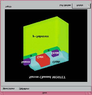
3 NARROW-CHANNEL MOSFET Davinci provides accurate simulation of deep submicron devices via self-consistent solutions of carrier energy balance equations with Poisson's equation and the current-continuity equations. capability is illustrated for a narrow-channel MOSFET. TSUPREM-4 was used to simulate a cross-section that includes the channel width. The doping, regions and electrodes were then extruded to form the source and drain diffused regions, source and drain contacts, and polysilic gate. The complete structure is shown in the left figure. Potential contours at the bias corresponding to maximum substrate current are shown in the mi figure. Drain and substrate characteristics, including the effects of electron temperature variatio are shown in the gure on the right. 3 of 7 2/22/01 5:50 PM

4 4 of 7 2/22/01 5:50 PM


5 EEPROM SIMULATION In this example, Davinci is used to simulate the programming characteristics of an EEPROM structure. 3D simulation is required for this example because the floating gate overlap of the field oxide makes an important contribution to the cell capacitance. To create the simulation structure, a 2D cross-section simulated with TSUPREM-4 is passed in Davinci and is extruded in the third dimension, as shown in the left figure. The center figure sho impact ionization which occurs during programming. The internal electrode structure can also b seen. Programming and erase are then simulated to calculate the threshold voltage as a function of ti (right figure). The programming mechanism is hot electron injection at the drain. Erase is via Fowler-Nordheim tunneling. This example demonstrates use of Davinci with the Programmable Device AAM. 5 of 7 2/22/01 5:50 PM

6 DAVINCI SPECIFICATIONS SIMULATION FEATURES Self consistently solves Poisson's equation, the electron and hole current-continuity equations, the electron and hole energy balance equations and the lattice heat equation. Steady state, transient and AC-small signal analysis. Current-continuity solutions in insulators. Arbitrary doping from analytic functions, tables and process simulation. Voltage, current or charge boundary conditions for electrodes. Lumped elements (R, L, C), contact resistance, Schottky contacts. Supports multiple materials such as Si, Ge, GaAs, SiGe, AlGaAs and SiC, as well as arbitrary user-defined materials. Automatic I-V curve tracing and time-step algorithms. Robust solution methods and algorithms. Extraction of device parameters such as threshold voltage (Vt), subthreshold slope, saturation current (Idsat), bipolar current gain ( ), cutoff frequency (ft) and sheet resista as well as arbitrary user-defined quantities. Optimization for tuning device performance and model calibration. PHYSICAL MODELS Shockley-Read-Hall and Auger recombination. Recombination including tunneling. Mobility dependencies on impurity concentration, lattice temperature, carrier concentratio carrier energy, parallel and perpendicular electric fields. Band gap narrowing. Band-to-band tunneling. Band-to-band recombination. Fixed oxide charge and fast interface states. Gate current based on temperature. Field-, carrier energy- and lattice temperature-dependent impact ionization. Energy balance models for both elemental and compound materials. Photogeneration of carriers and single event upset (SEU). Fermi-Dirac and Boltzmann statistics. Gate current models: ÒLucky electron-model and angle-dependent model. Non-Maxwellian generation function, appropriate for modeling gate current. INPUT/OUTPUT Accepts input structures directly from TSUPREM-4 process simulation. Supported within Taurus-WorkBench. 3D visualization via Davinci standard graphics and Taurus-Visual. Menu-driven interface with context-sensitive help. 6 of 7 2/22/01 5:50 PM
7 ADVANCED APPLICATION MODULES Advanced Application Modules (AAMs) have been developed for Davinci to address specialized technology needs. AAMs optionally available for Davinci include: Circuit Analysis AAM. Lattice Temperature AAM. Programmable Device AAM. Heterojunction Device AAM. Anisotropic Materials AAM. Trapped Charge AAM. Optical Device AAM. SYSTEM REQUIREMENTS Platforms: UNIX workstations from DEC. Hewlett-Packard, IBM and Sun Microsystems. Memory: 185 Mbytes (30,000-node version of Davinci). Disk space: 19 Mbytes. About Avant! Solutions & Products Tech Support Electronics Journal Investor Relations News Community EDA Mall Search Sitemap Contacts Home 2001 Avant! Corporation. All rights reserved. Terms and Conditions 7 of 7 2/22/01 5:50 PM
CONTENTS. 2.2 Schrodinger's Wave Equation 31. PART I Semiconductor Material Properties. 2.3 Applications of Schrodinger's Wave Equation 34
 CONTENTS Preface x Prologue Semiconductors and the Integrated Circuit xvii PART I Semiconductor Material Properties CHAPTER 1 The Crystal Structure of Solids 1 1.0 Preview 1 1.1 Semiconductor Materials
PHYSICS OF SEMICONDUCTOR DEVICES
 PHYSICS OF SEMICONDUCTOR DEVICES PHYSICS OF SEMICONDUCTOR DEVICES by J. P. Colinge Department of Electrical and Computer Engineering University of California, Davis C. A. Colinge Department of Electrical
Fundamentals of Power Semiconductor Devices
 В. Jayant Baliga Fundamentals of Power Semiconductor Devices 4y Spri ringer Contents Preface vii Chapter 1 Introduction 1 1.1 Ideal and Typical Power Switching Waveforms 3 1.2 Ideal and Typical Power Device
FUNDAMENTALS OF MODERN VLSI DEVICES
 19-13- FUNDAMENTALS OF MODERN VLSI DEVICES YUAN TAUR TAK H. MING CAMBRIDGE UNIVERSITY PRESS Physical Constants and Unit Conversions List of Symbols Preface page xi xiii xxi 1 INTRODUCTION I 1.1 Evolution
Semiconductor Devices
 Semiconductor Devices Modelling and Technology Source Electrons Gate Holes Drain Insulator Nandita DasGupta Amitava DasGupta SEMICONDUCTOR DEVICES Modelling and Technology NANDITA DASGUPTA Professor Department
NAME: Last First Signature
 UNIVERSITY OF CALIFORNIA, BERKELEY College of Engineering Department of Electrical Engineering and Computer Sciences EE 130: IC Devices Spring 2003 FINAL EXAMINATION NAME: Last First Signature STUDENT
Lecture 4. MOS transistor theory
 Lecture 4 MOS transistor theory 1.7 Introduction: A MOS transistor is a majority-carrier device, in which the current in a conducting channel between the source and the drain is modulated by a voltage
Solid State Devices- Part- II. Module- IV
 Solid State Devices- Part- II Module- IV MOS Capacitor Two terminal MOS device MOS = Metal- Oxide- Semiconductor MOS capacitor - the heart of the MOSFET The MOS capacitor is used to induce charge at the
Digital Electronics. By: FARHAD FARADJI, Ph.D. Assistant Professor, Electrical and Computer Engineering, K. N. Toosi University of Technology
 K. N. Toosi University of Technology Chapter 7. Field-Effect Transistors By: FARHAD FARADJI, Ph.D. Assistant Professor, Electrical and Computer Engineering, K. N. Toosi University of Technology http://wp.kntu.ac.ir/faradji/digitalelectronics.htm
Semiconductor Device Physics and Simulation
 Semiconductor Device Physics and Simulation MICRODEVICES Physics and Fabrication Technologies Series Editors: Ivor Brodie and Arden Sher SRI International Menlo Park, California Recent volumes in the series:
value of W max for the device. The at band voltage is -0.9 V. Problem 5: An Al-gate n-channel MOS capacitor has a doping of N a = cm ;3. The oxi
 Prof. Jasprit Singh Fall 2001 EECS 320 Homework 10 This homework is due on December 6 Problem 1: An n-type In 0:53 Ga 0:47 As epitaxial layer doped at 10 16 cm ;3 is to be used as a channel in a FET. A
Department of Electrical Engineering IIT Madras
 Department of Electrical Engineering IIT Madras Sample Questions on Semiconductor Devices EE3 applicants who are interested to pursue their research in microelectronics devices area (fabrication and/or
Session 3: Solid State Devices. Silicon on Insulator
 Session 3: Solid State Devices Silicon on Insulator 1 Outline A B C D E F G H I J 2 Outline Ref: Taurand Ning 3 SOI Technology SOl materials: SIMOX, BESOl, and Smart Cut SIMOX : Synthesis by IMplanted
Sub-Threshold Region Behavior of Long Channel MOSFET
 Sub-threshold Region - So far, we have discussed the MOSFET behavior in linear region and saturation region - Sub-threshold region is refer to region where Vt is less than Vt - Sub-threshold region reflects
UNIT 3: FIELD EFFECT TRANSISTORS
 FIELD EFFECT TRANSISTOR: UNIT 3: FIELD EFFECT TRANSISTORS The field effect transistor is a semiconductor device, which depends for its operation on the control of current by an electric field. There are
MSE 410/ECE 340: Electrical Properties of Materials Fall 2016 Micron School of Materials Science and Engineering Boise State University
 MSE 410/ECE 340: Electrical Properties of Materials Fall 2016 Micron School of Materials Science and Engineering Boise State University Practice Final Exam 1 Read the questions carefully Label all figures
MOSFET Parasitic Elements
 MOSFET Parasitic Elements Three MITs of the ay Components of the source resistance and their influence on g m and R d Gate-induced drain leakage (GIL) and its effect on lowest possible leakage current
MOSFET short channel effects
 MOSFET short channel effects overview Five different short channel effects can be distinguished: velocity saturation drain induced barrier lowering (DIBL) impact ionization surface scattering hot electrons
Three Terminal Devices
 Three Terminal Devices - field effect transistor (FET) - bipolar junction transistor (BJT) - foundation on which modern electronics is built - active devices - devices described completely by considering
FIELD EFFECT TRANSISTOR (FET) 1. JUNCTION FIELD EFFECT TRANSISTOR (JFET)
 1. JUNCTION FIELD EFFECT TRANSISTOR (JFET)") FIELD EFFECT TRANSISTOR (FET) The field-effect transistor (FET) is a three-terminal device used for a variety of applications that match, to a large extent, those of the BJT transistor. Although there
FIELD EFFECT TRANSISTOR (FET) The field-effect transistor (FET) is a three-terminal device used for a variety of applications that match, to a large extent, those of the BJT transistor. Although there
DesignofaRad-HardLibraryof DigitalCellsforSpaceApplications
 DesignofaRad-HardLibraryof DigitalCellsforSpaceApplications Alberto Stabile, Valentino Liberali and Cristiano Calligaro stabile@dti.unimi.it, liberali@dti.unimi.it, c.calligaro@redcatdevices.it Department
Introduction to semiconductor technology
 Introduction to semiconductor technology Outline 7 Field effect transistors MOS transistor current equation" MOS transistor channel mobility Substrate bias effect 7 Bipolar transistors Introduction Minority
VALLIAMMAI ENGINEERING COLLEGE SRM Nagar, Kattankulathur
 VALLIAMMAI ENGINEERING COLLEGE SRM Nagar, Kattankulathur 603 203. DEPARTMENT OF ELECTRONICS & COMMUNICATION ENGINEERING SUBJECT QUESTION BANK : EC6201 ELECTRONIC DEVICES SEM / YEAR: II / I year B.E.ECE
Review Energy Bands Carrier Density & Mobility Carrier Transport Generation and Recombination
 Review Energy Bands Carrier Density & Mobility Carrier Transport Generation and Recombination Current Transport: Diffusion, Thermionic Emission & Tunneling For Diffusion current, the depletion layer is
Semiconductor Physics and Devices
 Metal-Semiconductor and Semiconductor Heterojunctions The Metal-Oxide-Semiconductor Field-Effect Transistor (MOSFET) is one of two major types of transistors. The MOSFET is used in digital circuit, because
FET(Field Effect Transistor)
") Field Effect Transistor: Construction and Characteristic of JFETs. Transfer Characteristic. CS,CD,CG amplifier and analysis of CS amplifier MOSFET (Depletion and Enhancement) Type, Transfer Characteristic,
Field Effect Transistor: Construction and Characteristic of JFETs. Transfer Characteristic. CS,CD,CG amplifier and analysis of CS amplifier MOSFET (Depletion and Enhancement) Type, Transfer Characteristic,
Lecture 14. Field Effect Transistor (FET) Sunday 26/11/2017 FET 1-1
 Sunday 26/11/2017 FET 1-1") Lecture 14 Field Effect Transistor (FET) Sunday 26/11/2017 FET 1-1 Outline Introduction to FET transistors Types of FET Transistors Junction Field Effect Transistor (JFET) Characteristics Construction
Lecture 14 Field Effect Transistor (FET) Sunday 26/11/2017 FET 1-1 Outline Introduction to FET transistors Types of FET Transistors Junction Field Effect Transistor (JFET) Characteristics Construction
Index. Cambridge University Press Fundamentals of Modern VLSI Devices: Second Edition Yuan Taur and Tak H. Ning.
 abrupt junction, 38 acceptor, 17 acceptor level, 18 9 access transistor, 477 8, 496 accumulation, 76 7 accumulation layer, 250 charge density, 250 resistance, 274 5 sheet resistivity, 251 ac equivalent
Active Technology for Communication Circuits
 EECS 242: Active Technology for Communication Circuits UC Berkeley EECS 242 Copyright Prof. Ali M Niknejad Outline Comparison of technology choices for communication circuits Si npn, Si NMOS, SiGe HBT,
EE 5611 Introduction to Microelectronic Technologies Fall Thursday, September 04, 2014 Lecture 02
 EE 5611 Introduction to Microelectronic Technologies Fall 2014 Thursday, September 04, 2014 Lecture 02 1 Lecture Outline Review on semiconductor materials Review on microelectronic devices Example of microelectronic
Semiconductor Devices Lecture 5, pn-junction Diode
 Semiconductor Devices Lecture 5, pn-junction Diode Content Contact potential Space charge region, Electric Field, depletion depth Current-Voltage characteristic Depletion layer capacitance Diffusion capacitance
CHAPTER 8 The PN Junction Diode
 CHAPTER 8 The PN Junction Diode Consider the process by which the potential barrier of a PN junction is lowered when a forward bias voltage is applied, so holes and electrons can flow across the junction
Lecture 17. Field Effect Transistor (FET) FET 1-1
 FET 1-1") Lecture 17 Field Effect Transistor (FET) FET 1-1 Outline ntroduction to FET transistors Comparison with BJT transistors FET Types Construction and Operation of FET Characteristics Of FET Examples FET 1-2
Lecture 17 Field Effect Transistor (FET) FET 1-1 Outline ntroduction to FET transistors Comparison with BJT transistors FET Types Construction and Operation of FET Characteristics Of FET Examples FET 1-2
Tunneling Field Effect Transistors for Low Power ULSI
 Tunneling Field Effect Transistors for Low Power ULSI Byung-Gook Park Inter-university Semiconductor Research Center and School of Electrical and Computer Engineering Seoul National University Outline
FET. Field Effect Transistors ELEKTRONIKA KONTROL. Eka Maulana, ST, MT, M.Eng. Universitas Brawijaya. p + S n n-channel. Gate. Basic structure.
 FET Field Effect Transistors ELEKTRONIKA KONTROL Basic structure Gate G Source S n n-channel Cross section p + p + p + G Depletion region Drain D Eka Maulana, ST, MT, M.Eng. Universitas Brawijaya S Channel
UNIT 3 Transistors JFET
 UNIT 3 Transistors JFET Mosfet Definition of BJT A bipolar junction transistor is a three terminal semiconductor device consisting of two p-n junctions which is able to amplify or magnify a signal. It
ECE 3040 Dr. Alan Doolittle.
 ECE 3040 Dr. Alan Doolittle I have thoroughly enjoyed meeting each of you and hope that I have had a positive influence on your carriers. Please feel free to consult with me in your future work. If I can
6. Field-Effect Transistor
 6. Outline: Introduction to three types of FET: JFET MOSFET & CMOS MESFET Constructions, Characteristics & Transfer curves of: JFET & MOSFET Introduction The field-effect transistor (FET) is a threeterminal
Power MOSFET Zheng Yang (ERF 3017,
 ECE442 Power Semiconductor Devices and Integrated Circuits Power MOSFET Zheng Yang (ERF 3017, email: yangzhen@uic.edu) Evolution of low-voltage (
ATV 2011: Computer Engineering
 ATV 2011: Technology Trends in Computer Engineering Professor Per Larsson-Edefors ATV 2011, L1, Per Larsson-Edefors Page 1 Solid-State Devices www.cse.chalmers.se/~perla/ugrad/ SemTech/Lectures_2000.pdf
MTLE-6120: Advanced Electronic Properties of Materials. Semiconductor transistors for logic and memory. Reading: Kasap
 MTLE-6120: Advanced Electronic Properties of Materials 1 Semiconductor transistors for logic and memory Reading: Kasap 6.6-6.8 Vacuum tube diodes 2 Thermionic emission from cathode Electrons collected
Field-Effect Transistor (FET) is one of the two major transistors; FET derives its name from its working mechanism;
 is one of the two major transistors; FET derives its name from its working mechanism;") Chapter 3 Field-Effect Transistors (FETs) 3.1 Introduction Field-Effect Transistor (FET) is one of the two major transistors; FET derives its name from its working mechanism; The concept has been known
Chapter 3 Field-Effect Transistors (FETs) 3.1 Introduction Field-Effect Transistor (FET) is one of the two major transistors; FET derives its name from its working mechanism; The concept has been known
MOS TRANSISTOR THEORY
 MOS TRANSISTOR THEORY Introduction A MOS transistor is a majority-carrier device, in which the current in a conducting channel between the source and the drain is modulated by a voltage applied to the
Lecture 15. Field Effect Transistor (FET) Wednesday 29/11/2017 MOSFET 1-1
 Wednesday 29/11/2017 MOSFET 1-1") Lecture 15 Field Effect Transistor (FET) Wednesday 29/11/2017 MOSFET 1-1 Outline MOSFET transistors Introduction to MOSFET MOSFET Types epletion-type MOSFET Characteristics Comparison between JFET and
Lecture 15 Field Effect Transistor (FET) Wednesday 29/11/2017 MOSFET 1-1 Outline MOSFET transistors Introduction to MOSFET MOSFET Types epletion-type MOSFET Characteristics Comparison between JFET and
Basic Electronics. Introductory Lecture Course for. Technology and Instrumentation in Particle Physics Chicago, Illinois June 9-14, 2011
 Basic Electronics Introductory Lecture Course for Technology and Instrumentation in Particle Physics 2011 Chicago, Illinois June 9-14, 2011 Presented By Gary Drake Argonne National Laboratory Session 3
Chapter 1. Introduction
 Chapter 1 Introduction 1.1 Introduction of Device Technology Digital wireless communication system has become more and more popular in recent years due to its capability for both voice and data communication.
A New SiGe Base Lateral PNM Schottky Collector. Bipolar Transistor on SOI for Non Saturating. VLSI Logic Design
 A ew SiGe Base Lateral PM Schottky Collector Bipolar Transistor on SOI for on Saturating VLSI Logic Design Abstract A novel bipolar transistor structure, namely, SiGe base lateral PM Schottky collector
ECE520 VLSI Design. Lecture 2: Basic MOS Physics. Payman Zarkesh-Ha
 ECE520 VLSI Design Lecture 2: Basic MOS Physics Payman Zarkesh-Ha Office: ECE Bldg. 230B Office hours: Wednesday 2:00-3:00PM or by appointment E-mail: pzarkesh@unm.edu Slide: 1 Review of Last Lecture Semiconductor
Student Lecture by: Giangiacomo Groppi Joel Cassell Pierre Berthelot September 28 th 2004
 Student Lecture by: Giangiacomo Groppi Joel Cassell Pierre Berthelot September 28 th 2004 Lecture outline Historical introduction Semiconductor devices overview Bipolar Junction Transistor (BJT) Field
Lecture 4 -- Tuesday, Sept. 19: Non-uniform injection and/or doping. Diffusion. Continuity/conservation. The five basic equations.
 6.012 ELECTRONIC DEVICES AND CIRCUITS Schedule -- Fall 1995 (8/31/95 version) Recitation 1 -- Wednesday, Sept. 6: Review of 6.002 models for BJT. Discussion of models and modeling; motivate need to go
Simulation of MOSFETs, BJTs and JFETs. At and Near the Pinch-off Region. Xuan Yang
 Simulation of MOSFETs, BJTs and JFETs At and Near the Pinch-off Region by Xuan Yang A Thesis Presented in Partial Fulfillment of the Requirements for the Degree Master of Science Approved November 2011
ECE 440 Lecture 29 : Introduction to the BJT-I Class Outline:
 ECE 440 Lecture 29 : Introduction to the BJT-I Class Outline: Narrow-Base Diode BJT Fundamentals BJT Amplification Things you should know when you leave Key Questions How does the narrow-base diode multiply
CHAPTER 8 The PN Junction Diode
 CHAPTER 8 The PN Junction Diode Consider the process by which the potential barrier of a PN junction is lowered when a forward bias voltage is applied, so holes and electrons can flow across the junction
Contents. 1.1 Brief of Power Device Design Current Status of Power Semiconductor Devices Power MOSFETs... 3
 Contents Abstract (in Chinese) Abstract (in English) Acknowledgments (in Chinese) Contents Table Lists Figure Captions i iv viii ix xv xvii Chapter 1 Introduction..1 1.1 Brief of Power Device Design. 1
Analog and Telecommunication Electronics
 Politecnico di Torino - ICT School Analog and Telecommunication Electronics F2 Active power devices»mos»bjt» IGBT, TRIAC» Safe Operating Area» Thermal analysis 30/05/2012-1 ATLCE - F2-2011 DDC Lesson F2:
I E I C since I B is very small
 Figure 2: Symbols and nomenclature of a (a) npn and (b) pnp transistor. The BJT consists of three regions, emitter, base, and collector. The emitter and collector are usually of one type of doping, while
Lecture #29. Moore s Law
 Lecture #29 ANNOUNCEMENTS HW#15 will be for extra credit Quiz #6 (Thursday 5/8) will include MOSFET C-V No late Projects will be accepted after Thursday 5/8 The last Coffee Hour will be held this Thursday
Lecture 2 p-n junction Diode characteristics. By Asst. Prof Dr. Jassim K. Hmood
 Electronic I Lecture 2 p-n junction Diode characteristics By Asst. Prof Dr. Jassim K. Hmood THE p-n JUNCTION DIODE The pn junction diode is formed by fabrication of a p-type semiconductor region in intimate
Insulated Gate Bipolar Transistor (IGBT)
") nsulated Gate Bipolar Transistor (GBT) Comparison between BJT and MOS power devices: BJT MOS pros cons pros cons low V O thermal instability thermal stability high R O at V MAX > 400 V high C current complex
nsulated Gate Bipolar Transistor (GBT) Comparison between BJT and MOS power devices: BJT MOS pros cons pros cons low V O thermal instability thermal stability high R O at V MAX > 400 V high C current complex
EFFECT OF THRESHOLD VOLTAGE AND CHANNEL LENGTH ON DRAIN CURRENT OF SILICON N-MOSFET
 EFFECT OF THRESHOLD VOLTAGE AND CHANNEL LENGTH ON DRAIN CURRENT OF SILICON N-MOSFET A.S.M. Bakibillah Nazibur Rahman Dept. of Electrical & Electronic Engineering, American International University Bangladesh
EE301 Electronics I , Fall
 EE301 Electronics I 2018-2019, Fall 1. Introduction to Microelectronics (1 Week/3 Hrs.) Introduction, Historical Background, Basic Consepts 2. Rewiev of Semiconductors (1 Week/3 Hrs.) Semiconductor materials
Quantum Condensed Matter Physics Lecture 16
 Quantum Condensed Matter Physics Lecture 16 David Ritchie QCMP Lent/Easter 2018 http://www.sp.phy.cam.ac.uk/drp2/home 16.1 Quantum Condensed Matter Physics 1. Classical and Semi-classical models for electrons
CHAPTER 8 The pn Junction Diode
 CHAPTER 8 The pn Junction Diode Consider the process by which the potential barrier of a pn junction is lowered when a forward bias voltage is applied, so holes and electrons can flow across the junction
R. W. Erickson. Department of Electrical, Computer, and Energy Engineering University of Colorado, Boulder
 R. W. Erickson Department of Electrical, Computer, and Energy Engineering University of Colorado, Boulder pn junction! Junction diode consisting of! p-doped silicon! n-doped silicon! A p-n junction where
CHAPTER I INTRODUCTION
 CHAPTER I INTRODUCTION High performance semiconductor devices with better voltage and current handling capability are required in different fields like power electronics, computer and automation. Since
DC Analysis of InP/GaAsSb DHBT Device Er. Ankit Sharma 1, Dr. Sukhwinder Singh 2
 IOSR Journal of Electronics and Communication Engineering (IOSR-JECE) e-issn: 2278-2834,p- ISSN: 2278-8735.Volume 10, Issue 5, Ver. I (Sep - Oct.2015), PP 48-52 www.iosrjournals.org DC Analysis of InP/GaAsSb
Lecture Course. SS Module PY4P03. Dr. P. Stamenov
 Semiconductor Devices - 2013 Lecture Course Part of SS Module PY4P03 Dr. P. Stamenov School of Physics and CRANN, Trinity College, Dublin 2, Ireland Hilary Term, TCD 01 st of Feb 13 Diode Current Components
INTERNATIONAL JOURNAL OF APPLIED ENGINEERING RESEARCH, DINDIGUL Volume 1, No 3, 2010
 Low Power CMOS Inverter design at different Technologies Vijay Kumar Sharma 1, Surender Soni 2 1 Department of Electronics & Communication, College of Engineering, Teerthanker Mahaveer University, Moradabad
Session 10: Solid State Physics MOSFET
 Session 10: Solid State Physics MOSFET 1 Outline A B C D E F G H I J 2 MOSCap MOSFET Metal-Oxide-Semiconductor Field-Effect Transistor: Al (metal) SiO2 (oxide) High k ~0.1 ~5 A SiO2 A n+ n+ p-type Si (bulk)
improving further the mobility, and therefore the channel conductivity. The positive pattern definition proposed by Hirayama [6] was much improved in
![improving further the mobility, and therefore the channel conductivity. The positive pattern definition proposed by Hirayama [6] was much improved in](/thumbs/91/107553446.jpg "improving further the mobility, and therefore the channel conductivity. The positive pattern definition proposed by Hirayama [6] was much improved in") The two-dimensional systems embedded in modulation-doped heterostructures are a very interesting and actual research field. The FIB implantation technique can be successfully used to fabricate using these
The two-dimensional systems embedded in modulation-doped heterostructures are a very interesting and actual research field. The FIB implantation technique can be successfully used to fabricate using these
SCALING AND NUMERICAL SIMULATION ANALYSIS OF 50nm MOSFET INCORPORATING DIELECTRIC POCKET (DP-MOSFET)
") SCALING AND NUMERICAL SIMULATION ANALYSIS OF 50nm MOSFET INCORPORATING DIELECTRIC POCKET (DP-MOSFET) Zul Atfyi Fauzan M. N., Ismail Saad and Razali Ismail Faculty of Electrical Engineering, Universiti
SCALING AND NUMERICAL SIMULATION ANALYSIS OF 50nm MOSFET INCORPORATING DIELECTRIC POCKET (DP-MOSFET) Zul Atfyi Fauzan M. N., Ismail Saad and Razali Ismail Faculty of Electrical Engineering, Universiti
SRM INSTITUTE OF SCIENCE AND TECHNOLOGY (DEEMED UNIVERSITY)
") SRM INSTITUTE OF SCIENCE AND TECHNOLOGY (DEEMED UNIVERSITY) QUESTION BANK I YEAR B.Tech (II Semester) ELECTRONIC DEVICES (COMMON FOR EC102, EE104, IC108, BM106) UNIT-I PART-A 1. What are intrinsic and
SRM INSTITUTE OF SCIENCE AND TECHNOLOGY (DEEMED UNIVERSITY) QUESTION BANK I YEAR B.Tech (II Semester) ELECTRONIC DEVICES (COMMON FOR EC102, EE104, IC108, BM106) UNIT-I PART-A 1. What are intrinsic and
NOVEL 4H-SIC BIPOLAR JUNCTION TRANSISTOR (BJT) WITH IMPROVED CURRENT GAIN
 WITH IMPROVED CURRENT GAIN") NOVEL 4H-SIC BIPOLAR JUNCTION TRANSISTOR (BJT) WITH IMPROVED CURRENT GAIN Thilini Daranagama 1, Vasantha Pathirana 2, Florin Udrea 3, Richard McMahon 4 1,2,3,4 The University of Cambridge, Cambridge, United
NOVEL 4H-SIC BIPOLAR JUNCTION TRANSISTOR (BJT) WITH IMPROVED CURRENT GAIN Thilini Daranagama 1, Vasantha Pathirana 2, Florin Udrea 3, Richard McMahon 4 1,2,3,4 The University of Cambridge, Cambridge, United
UNIT-VI FIELD EFFECT TRANSISTOR. 1. Explain about the Field Effect Transistor and also mention types of FET s.
 UNIT-I FIELD EFFECT TRANSISTOR 1. Explain about the Field Effect Transistor and also mention types of FET s. The Field Effect Transistor, or simply FET however, uses the voltage that is applied to their
KOM2751 Analog Electronics :: Dr. Muharrem Mercimek :: YTU - Control and Automation Dept. 1 6 FIELD-EFFECT TRANSISTORS
 KOM2751 Analog Electronics :: Dr. Muharrem Mercimek :: YTU - Control and Automation Dept. 1 6 FIELD-EFFECT TRANSISTORS Most of the content is from the textbook: Electronic devices and circuit theory, Robert
Reg. No. : Question Paper Code : B.E./B.Tech. DEGREE EXAMINATION, NOVEMBER/DECEMBER Second Semester
 WK 5 Reg. No. : Question Paper Code : 27184 B.E./B.Tech. DEGREE EXAMINATION, NOVEMBER/DECEMBER 2015. Time : Three hours Second Semester Electronics and Communication Engineering EC 6201 ELECTRONIC DEVICES
FIELD EFFECT TRANSISTORS MADE BY : GROUP (13)/PM
/PM") FIELD EFFECT TRANSISTORS MADE BY : GROUP (13)/PM THE FIELD EFFECT TRANSISTOR (FET) In 1945, Shockley had an idea for making a solid state device out of semiconductors. He reasoned that a strong electrical
FIELD EFFECT TRANSISTORS MADE BY : GROUP (13)/PM THE FIELD EFFECT TRANSISTOR (FET) In 1945, Shockley had an idea for making a solid state device out of semiconductors. He reasoned that a strong electrical
EDC UNIT IV- Transistor and FET Characteristics EDC Lesson 9- ", Raj Kamal, 1
 EDC UNIT IV- Transistor and FET Characteristics Lesson-9: JFET and Construction of JFET 2008 EDC Lesson 9- ", Raj Kamal, 1 1. Transistor 2008 EDC Lesson 9- ", Raj Kamal, 2 Transistor Definition The transferred-resistance
Digital Integrated Circuits EECS 312
 14 12 10 8 6 Fujitsu VP2000 IBM 3090S Pulsar 4 IBM 3090 IBM RY6 CDC Cyber 205 IBM 4381 IBM RY4 2 IBM 3081 Apache Fujitsu M380 IBM 370 Merced IBM 360 IBM 3033 Vacuum Pentium II(DSIP) 0 1950 1960 1970 1980
Contribution of Gate Induced Drain Leakage to Overall Leakage and Yield Loss in Digital submicron VLSI Circuits
 Contribution of Gate Induced Drain Leakage to Overall Leakage and Yield Loss in Digital submicron VLSI Circuits Oleg Semenov, Andrzej Pradzynski * and Manoj Sachdev Dept. of Electrical and Computer Engineering,
Field Effect Transistor (FET) FET 1-1
 FET 1-1") Field Effect Transistor (FET) FET 1-1 Outline MOSFET transistors ntroduction to MOSFET MOSFET Types epletion-type MOSFET Characteristics Biasing Circuits and Examples Comparison between JFET and epletion-type
Field Effect Transistor (FET) FET 1-1 Outline MOSFET transistors ntroduction to MOSFET MOSFET Types epletion-type MOSFET Characteristics Biasing Circuits and Examples Comparison between JFET and epletion-type
In this lecture we will begin a new topic namely the Metal-Oxide-Semiconductor Field Effect Transistor.
 Solid State Devices Dr. S. Karmalkar Department of Electronics and Communication Engineering Indian Institute of Technology, Madras Lecture - 38 MOS Field Effect Transistor In this lecture we will begin
Conduction Characteristics of MOS Transistors (for fixed Vds)! Topic 2. Basic MOS theory & SPICE simulation. MOS Transistor
! Topic 2. Basic MOS theory & SPICE simulation. MOS Transistor") Conduction Characteristics of MOS Transistors (for fixed Vds)! Topic 2 Basic MOS theory & SPICE simulation Peter Cheung Department of Electrical & Electronic Engineering Imperial College London (Weste&Harris,
Conduction Characteristics of MOS Transistors (for fixed Vds)! Topic 2 Basic MOS theory & SPICE simulation Peter Cheung Department of Electrical & Electronic Engineering Imperial College London (Weste&Harris,
Topic 2. Basic MOS theory & SPICE simulation
 Topic 2 Basic MOS theory & SPICE simulation Peter Cheung Department of Electrical & Electronic Engineering Imperial College London (Weste&Harris, Ch 2 & 5.1-5.3 Rabaey, Ch 3) URL: www.ee.ic.ac.uk/pcheung/
Conduction Characteristics of MOS Transistors (for fixed Vds) Topic 2. Basic MOS theory & SPICE simulation. MOS Transistor
 Topic 2. Basic MOS theory & SPICE simulation. MOS Transistor") Conduction Characteristics of MOS Transistors (for fixed Vds) Topic 2 Basic MOS theory & SPICE simulation Peter Cheung Department of Electrical & Electronic Engineering Imperial College London (Weste&Harris,
Conduction Characteristics of MOS Transistors (for fixed Vds) Topic 2 Basic MOS theory & SPICE simulation Peter Cheung Department of Electrical & Electronic Engineering Imperial College London (Weste&Harris,
THE METAL-SEMICONDUCTOR CONTACT
 THE METAL-SEMICONDUCTOR CONTACT PROBLEM 1 To calculate the theoretical barrier height, built-in potential barrier, and maximum electric field in a metal-semiconductor diode for zero applied bias. Consider
Data Remanence in Semiconductor Devices
 Data Remanence in Semiconductor Devices Peter Gutmann IBM T.J.Watson Research Center Introduction 1996: Securely deleting data from magnetic media is hard 2001: Semiconductors aren t so easy either Magnetic
Intro to Electricity. Introduction to Transistors. Example Circuit Diagrams. Water Analogy
 Introduction to Transistors Transistors form the basic building blocks of all computer hardware. Invented by William Shockley, John Bardeen and Walter Brattain in 1947, replacing previous vaccuumtube technology
Alternatives to standard MOSFETs. What problems are we really trying to solve?
 Alternatives to standard MOSFETs A number of alternative FET schemes have been proposed, with an eye toward scaling up to the 10 nm node. Modifications to the standard MOSFET include: Silicon-in-insulator
Physics of Semiconductor Devices
 Physics of Semiconductor Devices S. M. SZE Member of the Technical Staff Bell Telephone Laboratories, Incorporated Murray Hill, New Jersey WILEY-INTERSCIENCE A Division of John Wiley & Sons New York London
Lecture 13. Metal Oxide Semiconductor Field Effect Transistor (MOSFET) MOSFET 1-1
 MOSFET 1-1") Lecture 13 Metal Oxide Semiconductor Field Effect Transistor (MOSFET) MOSFET 1-1 Outline Continue MOSFET Qualitative Operation epletion-type MOSFET Characteristics Biasing Circuits and Examples Enhancement-type
Lecture 13 Metal Oxide Semiconductor Field Effect Transistor (MOSFET) MOSFET 1-1 Outline Continue MOSFET Qualitative Operation epletion-type MOSFET Characteristics Biasing Circuits and Examples Enhancement-type
CHAPTER 6 DIGITAL CIRCUIT DESIGN USING SINGLE ELECTRON TRANSISTOR LOGIC
 94 CHAPTER 6 DIGITAL CIRCUIT DESIGN USING SINGLE ELECTRON TRANSISTOR LOGIC 6.1 INTRODUCTION The semiconductor digital circuits began with the Resistor Diode Logic (RDL) which was smaller in size, faster
ELECTRO-THERMAL TRANSIENT SIMULATION OF SILICON CARBIDE POWER MOSFET
 ELECTRO-THERMAL TRANSIENT SIMULATION OF SILICON CARBIDE POWER MOSFET Bejoy N. Pushpakaran, Stephen B. Bayne, Aderinto A. Ogunniyi Electrical and Computer Engineering, Texas Tech University, 2500 Broadway,
Field Effect Transistors (npn)
") Field Effect Transistors (npn) gate drain source FET 3 terminal device channel e - current from source to drain controlled by the electric field generated by the gate base collector emitter BJT 3 terminal
Field Effect Transistors (npn) gate drain source FET 3 terminal device channel e - current from source to drain controlled by the electric field generated by the gate base collector emitter BJT 3 terminal
Experiment 3. 3 MOSFET Drain Current Modeling. 3.1 Summary. 3.2 Theory. ELEC 3908 Experiment 3 Student#:
 Experiment 3 3 MOSFET Drain Current Modeling 3.1 Summary In this experiment I D vs. V DS and I D vs. V GS characteristics are measured for a silicon MOSFET, and are used to determine the parameters necessary
5.1 Introduction. transistor. Like the bipolar junction transistors (BJTs) we studied in Chapter 4,
 we studied in Chapter 4,") 5.1 Introduction In this chapter we introduce the second major type of transistor: the field-effect transistor. Like the bipolar junction transistors (BJTs) we studied in Chapter 4, field-effect transistors
5.1 Introduction In this chapter we introduce the second major type of transistor: the field-effect transistor. Like the bipolar junction transistors (BJTs) we studied in Chapter 4, field-effect transistors
Design cycle for MEMS
 Design cycle for MEMS Design cycle for ICs IC Process Selection nmos CMOS BiCMOS ECL for logic for I/O and driver circuit for critical high speed parts of the system The Real Estate of a Wafer MOS Transistor
EE70 - Intro. Electronics
 EE70 - Intro. Electronics Course website: ~/classes/ee70/fall05 Today s class agenda (November 28, 2005) review Serial/parallel resonant circuits Diode Field Effect Transistor (FET) f 0 = Qs = Qs = 1 2π
Organic Electronics. Information: Information: 0331a/ 0442/
 Organic Electronics (Course Number 300442 ) Spring 2006 Organic Field Effect Transistors Instructor: Dr. Dietmar Knipp Information: Information: http://www.faculty.iubremen.de/course/c30 http://www.faculty.iubremen.de/course/c30
CHAPTER 3 TWO DIMENSIONAL ANALYTICAL MODELING FOR THRESHOLD VOLTAGE
 49 CHAPTER 3 TWO DIMENSIONAL ANALYTICAL MODELING FOR THRESHOLD VOLTAGE 3.1 INTRODUCTION A qualitative notion of threshold voltage V th is the gate-source voltage at which an inversion channel forms, which