THE CRYSTAL OSCILLATOR CHARACTERIZATION FACILITY AT THE AEROSPACE CORPORATION
|
|
|
- Dustin Silvester Garrison
- 6 years ago
- Views:
Transcription
1 THE CRYSTAL OSCILLATOR CHARACTERIZATION FACILITY AT THE AEROSPACE CORPORATION S. Karuza, M. Rolenz, A. Moulthrop, A. Young, and V. Hunt The Aerospace Corporation El Segundo, CA 90245, USA Abstract At the present time, there is a need by the military for small, low-power, fast-warmup, and low g-sensitivity crystal oscillators for use in GPS receivers and transmitters in handheld survival radios and smart munitions. These units require a stable frequency source (crystal oscillators or small rubidium atomic clocks) for their operation. A variety of crystal oscillators are now on the market, and there is a need to evaluate the latest technology so that performance can be compared and evaluated. Insight into the characteristics of the various classes of crystal oscillators used by the contractors enables The Aerospace Corporation to identify the performance risks early in program development, which helps avoid schedule delays and later cost impacts. This paper describes a modernized clock-oscillator measurement facility that has been established at Aerospace to characterize these frequency sources in support of the military programs. MEASUREMENT SYSTEM In our frequency stability measurement system, we used the heterodyne single-mixer method [] to measure the frequency fluctuations of the frequency source under test, as shown in Figure. The signal from the oscillator to be tested is mixed with a reference oscillator of almost the same frequency as the oscillator under test. This is done so that one is left with a lower average frequency (beat frequency) for analysis without reducing the phase or frequency fluctuations themselves. In our measurement system, we have improved the measurement capability by using more up-to-date hardware and software, as will be described in our paper. Figure 2 shows the frequency stability measurement system. The system consists of the 5 and 0 MHz reference signals that are obtained from a HP507A cesium or a high-stability Oscilloquartz #8600 ovencontrolled crystal oscillator (OCXO) frequency sources. The cesium frequency standard is measured daily by a service supplied by the National Institute of Standards and Technology (NIST) to ensure that it meets the performance requirements. Figure 3 is a block diagram of our frequency stability measurement system. The measurement system consists of high-resolution time interval analyzers, mixers, frequency synthesizer, isolation amplifiers, and a PC that controls the instruments and processes the data. The high-resolution time-interval analyzer is manufactured by Guide Technology, Inc. The GT 654 board can make 2-digit time-interval measurements on each of its two channels simultaneously, with measurement rates that are thousands of times faster than counters, zero dead-time capability, and singleshot resolution at 75 ps. Two of these boards are in the PC. The boards measure the time period of the beat frequency out of the mixers. The input frequency of our boards is DC 400 MHz (2.0 GHz input channels optional), and we have measured beat periods from 0.0 sec to 0 sec in our measurement system. 34
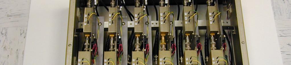
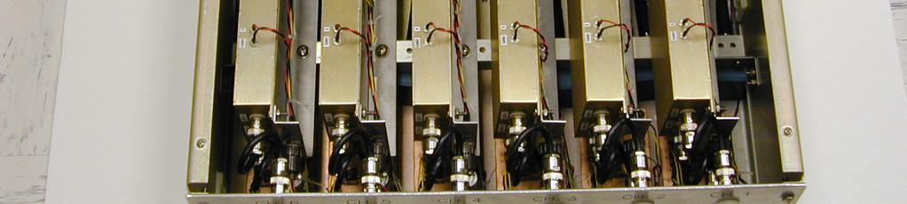
2 Figure 4 is a picture of our six-channel mixer system. Each channel consists of a mini-circuits mixer #ZAY-3, a low-pass filter, an amplifier, and a strobed threshold detector. Figure 5 is a schematic of our low-pass filter and amplifier. For the low-pass filter, we used an LT-028 low-noise operational amplifier to minimize the noise and pass only the desired beat frequency (usually 0 Hz). The low-pass output signal is then fed into an OP-5 operational amplifier output buffer. Figure 6 shows the frequency response of the low-pass filter and amplifier. The beat frequency signal then is input to a strobed threshold detector, as shown in Figure 7. The purpose of the threshold detector is to square up the sinusoidal beat frequency and prevent false triggering by the electronics to follow. This is accomplished by creating a dead zone in time after each crossing in which the threshold detector is disabled. The output of the threshold detector is then fed into the time-interval analyzer for measurement of its beat period. The Programmed Test Sources, Inc. PTS model #250M6NIGSX-5 low-noise frequency synthesizer is used to offset the frequency reference to obtain the desired beat frequency. In our previous system, we used a Fluke 660B frequency synthesizer, since the Fluke 660B frequency synthesizer had the lowest noise contribution of all the frequency synthesizers on the market at that time. The reason for having the low-noise frequency synthesizer is the synthesizer noise contributions to the system noise-floor. Unfortunately, Fluke has discontinued manufacturing and maintaining this synthesizer. Therefore, we looked at the new synthesizers on the market and found that the PTS synthesizer was the closest to the Fluke 660B frequency synthesizer in terms of noise floor. In our measurement system, we currently use Erbtec isolation amplifiers to isolate the signals between the DUTs, the references, and mixers. This eliminates reflections due to mismatch of impedance levels. These isolation amplifiers have a frequency range of to 00 MHz and a 00 db isolation capability. At this time, the Erbtec isolation amplifiers are no longer available, but there are other manufacturers that make similar amplifiers. While the Erbtec devices are excellent isolation amplifiers, ultimately we will replace them. We measured our system noise floor by using the frequency reference signal (HP507A cesium) that was also input into the device under test (DUT) port. Figure 8 shows the system noise floor and the HP507A cesium s performance. At a sampling period of second, the system noise floor Allan deviation is We also note that even if the system noise floor is better than our reference source (HP507A), we cannot measure any DUT that is better than the frequency reference source used. Guide Technology, Inc. provided a limited set of LabVIEW drivers for use with the GT654 time interval analyzer, as well as a full set of drivers written in the C programming language. Using dynamic link libraries, we accessed C drivers not supplied with the LabVIEW driver set. In LabVIEW we were then able to access all the required board functions with a graphical user interface. In our measurement system, we currently have two GT654 boards; each board has two channels with 2 MB of RAM, allowing us to measure four oscillators simultaneously. Figure 9 shows the LabVIEW control window of our four channels, with each window displaying in real time the fractional frequency fluctuation for 00 samples. To process phase data from each channel of the GT654 board, we use Hamilton Technical Services Stable-32 software. This program does the analysis of frequency stability. The software includes all the functions necessary to manipulate, analyze, and plot time and frequency stability data. Figure 0 shows a typical Allan deviation plot of a frequency standard, in this case a microcomputercontrolled crystal oscillator (MCXO). To characterize frequency standards over different temperature environments and profiles, we set up an automated temperature chamber, as shown in Figure. We used a Tenney JR temperature chamber that can range in temperature from 75 C to +200 C, ±0.3 degrees. The chamber uses a Watlow 942 microprocessor-based time and temperature profile controller, which interfaces with our PC over an RS232 interface. Custom drivers for the Watlow controller were written in the LabVIEW software so that we can program the chamber temperature profile, as shown in Figure
3 The chamber has its own temperature sensor (RTD), but to monitor the actual temperature of the device under test, we use a Stanford Research Systems, Inc. 6-channel thermocouple monitor model SR630 with a 0. C resolution. This monitor is also used to measure the actual current drawn by the device under test, by using a -ohm precision resistor in the power line of the device under test. The monitor is also linked to the LabVIEW software by means of a custom driver. Figure 3 shows the block diagram of the setup. Figure 4 shows a typical thermal data run on an oscillator. We have also developed a single sideband phase noise measurement system using the HP E5500 phase noise hardware with several Wenzel, Inc. low-phase noise reference oscillators. In addition, we have a Timing Solutions Corp. TSC 50 timeinterval analyzer for portable field use to measure frequency stability of oscillators that cannot be brought to our facility. CONCLUSIONS This paper has presented a description of the hardware and software of our crystal oscillator characterization facility at The Aerospace Corporation. We designed this system to be simple to use, and to provide a fast turnaround for characterization or verification of manufacturer data of any crystal oscillator. This facility is being used to support many military programs by assisting manufacturers in characterizing the oscillators for these programs. ACKNOWLEDGMENTS The authors are grateful to Gary Fisher for building the mixer box. REFERENCES [] D. A. Howe, D. W. Allan, and J. A. Barnes, 98, Properties of Signal Sources and Measurement Methods, in Proceedings of the 35th Annual Symposium on Frequency Control, May 98, Philadelphia, Pennsylvania, USA (IEEE Publication AD-A0870), pp. A A
4 OSCILLATOR UNDER TEST AMP f fo FREQUENCY REFERENCE AMP SYNTHESIZER FREQUENCY STANDARD fb =f - fo + other freq. LPF AMP ZERO-CROSSING DETECTOR fb = f - fo T b T b 2 T b n TIME INTERVAL COUNTER T b n COMPUTER Figure. Block Diagram of a Single Mixer Heterodyne Measurement Technique. 344
5 Figure 2. Frequency Stability Measurement System. HP-507A PTS-250 synthesizer 5 MHz Cesium reference Stable-32 software f f s F b = (f f s ) Tau = /f b f 2 DUT Ch DUT Ch2 0 MHz Guide Tech. #654 Time interval board PC computer Plotter f 6 DUT LabVIEW software Ch6 Guide Tech. #654 Time interval board Figure 3. Block Diagram of the Multichannel Frequency Stability Measurement System. 345
6 Figure 4. Multichannel Single Mixer System. 346
7 Gary Fisher /30/99 Analogamp.scm +5V +5V uf.uf k 0k IN uf 000pf M pf 00 LT028 2 NULL IN- V+ 6 4 IN+ OUT 5 V- NULL 2 3 NULL IN- V IN+ OUT 5 V- NULL OP-5 OUT uf.uf -5V -5V Figure 5. Circuit Diagram of the Low-Pass Filter and Amplifier. 00 Gain, db Frequency, Hz Figure 6. Plot of the Frequency Response of the Low-Pass Filter and Amplifier. 347
8 . +5V +5V INPUT.uf.uf 5K 0K.uf 0 LM 6/ LM 36 V+ VCC 4 Strobe 3 3 IN 4 IN 2 OUT GND 0 6 V- OUT 2 9 Strobe V V 0 PRE 9 Q CLK 2 D Q CLR +5V uf 4 PRE Q CLK 04 2 uf D 74 6 Q CLR OUT- +5V VCC GND 4.uf.uf.uf 7474 VCC VCC 4 7 GND 7 GND OUT-2 Figure 7. Schematic Diagram of the Zero-Crossing Threshold Detector..0E-0.0E- HP-507A Cs Reference.0E-2.0E-3.0E-4 System Noise Floor.0E-5.E-0.E+00.E+0.E+02.E+03.E+04 Figure 8. The Measured Allan Deviation of the Cesium Frequency Standard Reference and the Frequency Stability Measurement System Noise Floor. 348

9 Figure 9. Real-time Fractional Frequency Plot of the Multichannel Frequency Stability Measurement System. Figure 0. Plot of the Allan Deviation of a Microcomputer-Controlled Crystal Oscillator. 349


10 Figure. The Temperature Chamber. Figure 2. Computer-Controlled Temperature Chamber Temperature Profile Program. 350


11 Figure 3. Block Diagram of the Computer-Controlled Temperature Chamber System. Figure 4. Plot of a Temperature-Compensated Crystal Oscillator Fractional Frequency Response Due to Temperature Change. 35
12 352
Easy-to-Use RF Device & User-Friendly Windows Software
 itest+ PicoTime-1U Spec November 30, 2015 Low Cost/Profile High Resolution Frequency Stability Measurement Test Set Pico Second Resolution Instrument Easy-to-Use RF Device & User-Friendly Windows Software
THE MASTER CLOCK FACILITY AT USNO INFRASTRUCTURE
 THE MASTER CLOCK FACILITY AT USNO INFRASTRUCTURE Warren F. Walls U.S. Naval Observatory; Time Service Department 3450 Massachusetts Ave., NW; Washington, DC 20392 Email: Warren.Walls@Navy.mil Abstract
Clock Measurements Using the BI220 Time Interval Analyzer/Counter and Stable32
 Clock Measurements Using the BI220 Time Interval Analyzer/Counter and Stable32 W.J. Riley Hamilton Technical Services Beaufort SC 29907 USA Introduction This paper describes methods for making clock frequency
Compact VNA - TR7530. Extended Specifications EXTEND YOUR REACH TM
 Compact VNA - TR7530 TM Extended Specifications Frequency range: 20 khz - 3 GHz Wide output power adjustment range: -50 dbm to +5 dbm Dynamic range: 123 db (10 Hz IF bandwidth) typ. Measurement time per
Compact VNA - TR1300/1
 Compact VNA - TR1300/1 TM Extended Specifications Frequency range: 300 khz - 1.3 GHz Wide output power adjustment range: -55 dbm to +3 dbm Dynamic range: 135 db (10 Hz IF bandwidth) typ. Measurement time
PXIe Contents CALIBRATION PROCEDURE. Reconfigurable 6 GHz RF Vector Signal Transceiver with 200 MHz Bandwidth
 IBRATION PROCEDURE PXIe-5646 Reconfigurable 6 GHz Vector Signal Transceiver with 200 MHz Bandwidth This document contains the verification and adjustment procedures for the PXIe-5646 vector signal transceiver.
1 Introduction: frequency stability and accuracy
 Content 1 Introduction: frequency stability and accuracy... Measurement methods... 4 Beat Frequency method... 4 Advantages... 4 Restrictions... 4 Spectrum analyzer method... 5 Advantages... 5 Restrictions...
Victor S. Reinhardt and Charles B. Sheckells Hughes Space and Communications Company P. O. Box 92919, Los Angeles, CA 90009
 Published in the proceedings of the 31st NASA-DOD Precise Time and Time Interval Planning Meeting (Dana Point, California), 1999. REDUNDANT ATOMIC FREQUENCY STANDARD TIME KEEPING SYSTEM WITH SEAMLESS AFS
Calibration Techniques for the Home Lab
 Calibration Techniques for the Home Lab Jacques Audet VE2AZX jacaudet@videotron.ca Web: ve2azx.net September 2018 ve2azx.net 1 Summary - Using a reference multimeter as a calibrator for less accurate instruments.
PRELIMINARY. Logic: C = CMOS S = Sine Wave
 Description Q-Tech s microcomputer compensated crystal oscillator, MCXO, uses a high stability overtone SC-cut crystal with microprocessor controlled compensation. The self-temperature sensing resonator,
Reconfigurable 6 GHz RF Vector Signal Transceiver with 1 GHz Bandwidth
 CALIBRATION PROCEDURE PXIe-5840 Reconfigurable 6 GHz RF Vector Signal Transceiver with 1 GHz Bandwidth This document contains the verification procedures for the PXIe-5840 vector signal transceiver. Refer
1GHz low voltage LNA, mixer and VCO
 DESCRIPTION The is a combined RF amplifier, VCO with tracking bandpass filter and mixer designed for high-performance low-power communication systems from 800-1200MHz. The low-noise preamplifier has a
Cobalt Series 20 GHz EXTEND YOUR REACH TM
 Cobalt Series 20 GHz TM Frequency range: 100 khz - 20 GHz Wide output power range: -60 dbm to +10 dbm Dynamic range: 135 db (10 Hz IF bandwidth) typ. Measurement time per point: 10 µs per point, min typ.
Berkeley Nucleonics Corporation
 Berkeley Nucleonics Corporation A trusted source for quality and innovative instrumentation since 1963 Test And Measurement Nuclear Expertise RF/Microwave BNC at Our Core BNC Mission: Providing our customers
GPS10R - 10 MHz, GPS Disciplined, Rubidium Frequency Standards
 GPS10R - 10 MHz, GPS Disciplined, Rubidium Standards Key Features Completely self-contained units. No extra P.C Multiple 10 MHz Outputs plus other outputs needed. Full information available via LCD. RS232
Handy dandy little circuit #17 #17
 Handy dandy little circuit #17 #17 Download # 17 in PDF There are a lot of alarm systems on the market but you might be inclined to build your own. This little project can be put together using inexpensive
A NEW GENERATION PROGRAMMABLE PHASE/AMPLITUDE MEASUREMENT RECEIVER
 GENERAL A NEW GENERATION PROGRAMMABLE PHASE/AMPLITUDE MEASUREMENT RECEIVER by Charles H. Currie Scientific-Atlanta, Inc. 3845 Pleasantdale Road Atlanta, Georgia 30340 A new generation programmable, phase-amplitude
Chapter 6. Temperature Effects
 Chapter 6. Temperature Effects 6.1 Introduction This chapter documents the investigation into temperature drifts that can cause a receiver clock bias even when a stable reference is used. The first step
Low voltage LNA, mixer and VCO 1GHz
 DESCRIPTION The is a combined RF amplifier, VCO with tracking bandpass filter and mixer designed for high-performance low-power communication systems from 800-1200MHz. The low-noise preamplifier has a
A PC-BASED TIME INTERVAL COUNTER WITH 200 PS RESOLUTION
 A PC-BASED TIME INTERVAL COUNTER WITH 200 PS RESOLUTION Józef Kalisz and Ryszard Szplet Military University of Technology Kaliskiego 2, 00-908 Warsaw, Poland Tel: +48 22 6839016; Fax: +48 22 6839038 E-mail:
CHARACTERIZATION OF OP-AMP
 EXPERIMENT 4 CHARACTERIZATION OF OP-AMP OBJECTIVES 1. To sketch and briefly explain an operational amplifier circuit symbol and identify all terminals. 2. To list the amplifier stages in a typical op-amp
GPS10RBN - 10 MHz, GPS Disciplined Rubidium Frequency Standard
 GPS10RBN - 10 MHz, GPS Disciplined Rubidium Standard Completely self-contained unit. No extra P.C needed. Full information available via LCD. Rubidium Oscillator locked to GPS satellite signal. Accuracy
INTEGRATED CIRCUITS. AN109 Microprocessor-compatible DACs Dec
 INTEGRATED CIRCUITS 1988 Dec DAC products are designed to convert a digital code to an analog signal. Since a common source of digital signals is the data bus of a microprocessor, DAC circuits that are
ECE 363 FINAL (F16) 6 problems for 100 pts Problem #1: Fuel Pump Controller (18 pts)
 6 problems for 100 pts Problem #1: Fuel Pump Controller (18 pts)") ECE 363 FINAL (F16) NAME: 6 problems for 100 pts Problem #1: Fuel Pump Controller (18 pts) You are asked to design a high-side switch for a remotely operated fuel pump. You decide to use the IRF9520 power
ECE 363 FINAL (F16) NAME: 6 problems for 100 pts Problem #1: Fuel Pump Controller (18 pts) You are asked to design a high-side switch for a remotely operated fuel pump. You decide to use the IRF9520 power
1-Port USB VNA - R60 Extended Specifications
 TM 1- USB VNA - R60 Extended Specifications Patent US 9,291,657 - No test cable needed Frequency range: 1 MHz - 6 GHz Measurement time per point: 100 µs min typ. Automation programming in LabView, Python,
PHASE NOISE MEASUREMENT SYSTEMS
 PHASE NOISE MEASUREMENT SYSTEMS Item Type text; Proceedings Authors Lance, A. L.; Seal, W. D.; Labaar, F. Publisher International Foundation for Telemetering Journal International Telemetering Conference
Analysis of Phase Noise Profile of a 1.1 GHz Phase-locked Loop
 Analysis of Phase Noise Profile of a 1.1 GHz Phase-locked Loop J. Handique, Member, IAENG and T. Bezboruah, Member, IAENG 1 Abstract We analyzed the phase noise of a 1.1 GHz phaselocked loop system for
SA620 Low voltage LNA, mixer and VCO 1GHz
 INTEGRATED CIRCUITS Low voltage LNA, mixer and VCO 1GHz Supersedes data of 1993 Dec 15 2004 Dec 14 DESCRIPTION The is a combined RF amplifier, VCO with tracking bandpass filter and mixer designed for high-performance
Real-Time Phase Noise Analyzer
 Real-Time Phase Noise Analyzer May 12, 2017 Holzworth Instrumentation was founded on the sole premise of providing the industry s most accurate phase noise test systems, with a heavy emphasis on measurement
MAINTENANCE MANUAL TRANSMITTER/RECEIVER BOARD CMN-234A/B FOR MLSU141 & MLSU241 UHF MOBILE RADIO TABLE OF CONTENTS
 MAINTENANCE MANUAL TRANSMITTER/RECEIVER BOARD CMN-234A/B FOR MLSU141 & MLSU241 UHF MOBILE RADIO TABLE OF CONTENTS DESCRIPTION... 2 CIRCUIT ANALYSIS... 2 TRANSMITTER... 2 9-Voft Regulator... 2 Exciter...
Agilent AN 1275 Automatic Frequency Settling Time Measurement Speeds Time-to-Market for RF Designs
 Agilent AN 1275 Automatic Frequency Settling Time Measurement Speeds Time-to-Market for RF Designs Application Note Fast, accurate synthesizer switching and settling are key performance requirements in
THE MASTER CLOCK BUILDING AT USNO INFRASTRUCTURE
 THE MASTER CLOCK BUILDING AT USNO INFRASTRUCTURE Warren F. Walls U.S. Naval Observatory, Time Service Department 3450 Massachusetts Ave., NW; Washington, DC 20392, USA E-mail: Warren.Walls@Navy.mil Abstract
ADI 2006 RF Seminar. Chapter II RF/IF Components and Specifications for Receivers
 ADI 2006 RF Seminar Chapter II RF/IF Components and Specifications for Receivers 1 RF/IF Components and Specifications for Receivers Fixed Gain and Variable Gain Amplifiers IQ Demodulators Analog-to-Digital
Your Network. Optimized.
 Over 20 years of research both at the National Institute of Standards and Technology (NIST) and in private industry have been dedicated to the research and development of Symmetricom s phase noise and
ExacTime GPS Time & Frequency Generator
 TIMING, TEST & MEASUREMENT ExacTime 6000 GPS Time & Frequency Generator KEY FEATURES GPS Time and Frequency Reference Disciplined Quartz Oscillator Time Base Optional Disciplined Rubidium Oscillator Rapid
PRACTICAL PROBLEMS INVOLVING PHASE NOISE MEASUREMENTS
 33rdAnnual Precise Time and Time Interval (P77 1)Meeting PRACTICAL PROBLEMS INVOLVING PHASE NOISE MEASUREMENTS Warren F. Walls Femtosecond Systems, Inc. 4894 Van Gordon St., Ste. 301-N Wheat Ridge, CO
PXIe Contents. Required Software CALIBRATION PROCEDURE
 CALIBRATION PROCEDURE PXIe-5160 This document contains the verification and adjustment procedures for the PXIe-5160. Refer to ni.com/calibration for more information about calibration solutions. Contents
M5090. Extended Specifications EXTEND YOUR REACH TM
 M5090 Extended Specifications TM Frequency range: 300 khz - 8.5 GHz Wide output power adjustment range: -55 dbm to +5 dbm Dynamic range: 130 db (10 Hz IF bandwidth) typ. Measurement time per point: 70
SPECIFICATIONS: Subcarrier Frequency 5.5MHz adjustable, FM Modulated +/- 50KHz. 2nd 11MHz >40dB down from 5.5MHz
 Mini-kits AUDIO / SUBCARRIER KIT EME75 Version4 SPECIFICATIONS: Subcarrier Frequency 5.5MHz adjustable, FM Modulated +/- 50KHz Subcarrier Output 1.5v p-p Output @ 5.5MHz DESCRIPTION & FEATURES: The Notes
Easy-to-Use RF Device & User-Friendly Windows Software
 December 4, 2018 Low Cost / Profile High resolution Frequency Stability Measurement Test Set Pico Second Resolution Instrument Easy-to-Use RF Device & User-Friendly Windows Software APPLICATIONS Calibration
INC. MICROWAVE. A Spectrum Control Business
 DRO Selection Guide DIELECTRIC RESONATOR OSCILLATORS Model Number Frequency Free Running, Mechanically Tuned Mechanical Tuning BW (MHz) +10 MDR2100 2.5-6.0 +10 6.0-21.0 +20 Free Running, Mechanically Tuned,
GPS10RBN-26: 10 MHz, GPS Disciplined, Ultra Low Noise Rubidium Frequency Standard
 GPS10RBN-26: 10 MHz, GPS Disciplined, Ultra Low Noise Rubidium Standard Key Features Completely self-contained unit. No extra P.C needed. Full information available via LCD. Rubidium Oscillator locked
Accurate Phase Noise Measurements Made Cost Effective
 MTTS 2008 MicroApps Accurate Phase Noise Measurements Made Cost Effective author : Jason Breitbarth, PhD. Boulder, Colorado, USA Presentation Outline Phase Noise Intro Additive and Absolute Oscillator
Advanced bridge instrument for the measurement of the phase noise and of the short-term frequency stability of ultra-stable quartz resonators
 Advanced bridge instrument for the measurement of the phase noise and of the short-term frequency stability of ultra-stable quartz resonators F. Sthal, X. Vacheret, S. Galliou P. Salzenstein, E. Rubiola
1 UAT Test Procedure and Report
 1 UAT Test Procedure and Report These tests are performed to ensure that the UAT Transmitter will comply with the equipment performance tests during and subsequent to all normal standard operating conditions
A 3 TO 30 MHZ HIGH-RESOLUTION SYNTHESIZER CONSISTING OF A DDS, DIVIDE-AND-MIX MODULES, AND A M/N SYNTHESIZER. Richard K. Karlquist
 A 3 TO 30 MHZ HIGH-RESOLUTION SYNTHESIZER CONSISTING OF A DDS, -AND-MIX MODULES, AND A M/N SYNTHESIZER Richard K. Karlquist Hewlett-Packard Laboratories 3500 Deer Creek Rd., MS 26M-3 Palo Alto, CA 94303-1392
PARAMETER CONDITIONS TYPICAL PERFORMANCE Operating Supply Voltage 3.1V to 3.5V Supply Current V CC = 3.3V, LO applied 152mA
 DESCRIPTION LT5578 Demonstration circuit 1545A-x is a high linearity upconverting mixer featuring the LT5578. The LT 5578 is a high performance upconverting mixer IC optimized for output frequencies in
SPACECRAFT SIGNAL SOURCES PORTABLE TEST SYSTEM*
 SPACECRAFT SIGNAL SOURCES PORTABLE TEST SYSTEM* Albert Kirk, Paul Kuhnle, Richard Sydnor William Diener and David Stowers California Institute of Technology Jet Propulsion Laboratory Pasadena, California
Maintenance Manual TRANSMITTER/RECEIVER BOARD CMN-233 FOR MLSH041
 Maintenance Manual TRANSMITTER/RECEIVER BOARD CMN-233 FOR MLSH041 TABLE OF CONTENTS Page DESCRIPTION... 2 CIRCUIT ANALYSIS... 2 Transmitter... 2 9-volt Regulator... 2 Exciter... 2 40-Watt PA... 2 Antenna
Contents. CALIBRATION PROCEDURE NI 5421/ MS/s Arbitrary Waveform Generator
 CALIBRATION PROCEDURE NI 5421/5441 100 MS/s Arbitrary Waveform Generator This document contains the verification and adjustment procedures for the NI 5421/5441 arbitrary waveform generator. This calibration
DEVELOPMENT OF A PRIMARY REFERENCE CLOCK
 32nd Annual Precise Time and Time Interval (PTTI) Meeting DEVELOPMENT OF A PRIMARY REFERENCE CLOCK Clive Green Quartzlock (UK) Ltd. Gothic, Plymouth Rd., Devon, TQ9 5LH, UK Tel: +44 (0) 1803 862062; Fax:
Design of Frequency Characteristic Test Instrument Based on USB
 Design of Frequency Characteristic Test Instrument Based on USB Zhengling Wu, Nannan Zhang College of information and control engineering, Jilin Institute of Chemical Technology, Jilin, Jilin, P.R. China.
Frequency Distribution Design Basic Module Document version 4.1
 Frequency Distribution Design Basic Module Document version 4.1 One of the main components of the Frequency distribution is the Distribution Amplifier. In order to design a circuit suitable for this function,
3250 Series Spectrum Analyzer
 The most important thing we build is trust ADVANCED ELECTRONIC SOLUTIONS AVIATION SERVICES COMMUNICATIONS AND CONNECTIVITY MISSION SYSTEMS 3250 Series Spectrum Analyzer > Agenda Introduction
Time and Frequency Measurements for Oscillator Manufacturers
 Time and Frequency Measurements for Oscillator Manufacturers Using the FCA3000 and FCA3100 Series Timer/Counter/Analyzers Application Note Application Note Introduction Designing and manufacturing oscillators
Swept Wavelength Testing:
 Application Note 13 Swept Wavelength Testing: Characterizing the Tuning Linearity of Tunable Laser Sources In a swept-wavelength measurement system, the wavelength of a tunable laser source (TLS) is swept
SDI SPECTRADYNAMICS, INC GHZ RUBIDIUM FREQUENCY SYNTHESIZER OPERATING MANUAL
 SPECTRADYNAMICS, INC. 6.834 GHZ RUBIDIUM FREQUENCY SYNTHESIZER RB-1 OPERATING MANUAL SPECTRADYNAMICS, INC 1849 Cherry St. Unit 2 Louisville, CO 80027 Phone: (303) 665-1852 Fax: (303) 604-6088 www.spectradynamics.com
OTHER FEI PRODUCTS. FE-102A - CRYSTAL OSCILLATOR MHz WITH LOW PHASE NOISE: -172 dbc
 OTHER FEI PRODUCTS FE-102A - CRYSTAL OSCILLATOR OPERATION @100 MHz WITH LOW PHASE NOISE: -172 dbc FE-101A - CRYSTAL OSCILLATOR SUBMINIATURE OVEN CONTROLLED DESIGN, ONLY 1.27"X1.33"X1.33" WITH FAST WARM
Agilent CMM Fixture Electronics Clock/Crystal Measurement Module
 Agilent CMM Fixture Electronics Clock/Crystal Measurement Module Slide # 1 Having problems with clock? Frequency too high, over 3070 spec > 20MHz for any hybrid receivers (rcva) > 60MHz for clock receivers
THE TIME KEEPING SYSTEM FOR GPS BLOCK IIR
 THE TIME KEEPING SYSTEM FOR GPS BLOCK IIR H. C. RAWICZ; M. A. EPSTEIN and J. A. RAJAN ITT Aerospace/Communications Division 108 Kingsland Road, Clifton, NJ Abstract The precision time keeping system [TKS)
Written by Hans Summers Wednesday, 15 November :53 - Last Updated Wednesday, 15 November :07
 This is a phantastron divider based on the HP522 frequency counter circuit diagram. The input is a 2100Hz 15V peak-peak signal from my 2.1kHz oscillator project. Please take a look at the crystal oscillator
Differential Amplifiers
 Differential Amplifiers Benefits of Differential Signal Processing The Benefits Become Apparent when Trying to get the Most Speed and/or Resolution out of a Design Avoid Grounding/Return Noise Problems
TRANSDUCER INTERFACE APPLICATIONS
 TRANSDUCER INTERFACE APPLICATIONS Instrumentation amplifiers have long been used as preamplifiers in transducer applications. High quality transducers typically provide a highly linear output, but at a
THE Symmetricom test set has become a useful instrument
 IEEE TRANS. ON MICROWAVE THEORY AND TECHNIQUES, VOL. XX, NO. X, DECEMBER 2012 1 A transposed frequency technique for phase noise and frequency stability measurements John G. Hartnett, Travis Povey, Stephen
Signal Stability Analyzer
 A7-MX Now with Close-in Phase Noise personality Signal Stability Analyzer 50kHz to 65MHz Real Time Phase and Fractional Frequency Data View Time (Allan variance) and Frequency Domain (FFT) Analysis Data
Cost-Effective Traceability for Oscilloscope Calibration. Author: Peter B. Crisp Head of Metrology Fluke Precision Instruments, Norwich, UK
 Cost-Effective Traceability for Oscilloscope Calibration Author: Peter B. Crisp Head of Metrology Fluke Precision Instruments, Norwich, UK Abstract The widespread adoption of ISO 9000 has brought an increased
O C X O Oven Controlled Crystal Oscillators
 What is an OCXO? Relatively speaking, an OCXO performs in the ±0.01~±0.1 ppm range, a TCXO performs in the ±1~±3 ppm range while a non-compensated clock oscillator performs in the ±25, ±50 ppm range. A
General Guideline: CDC7005 as a Clock Synthesizer and Jitter Cleaner
 Application eport SCAA063 March 2003 General Guideline: CDC7005 as a Clock Synthesizer and Jitter Cleaner Firoj Kabir ABSTACT TI Clock Solutions This application report is a general guide for using the
Power Measurement Basics
 Back to Basics - 2006 Objectives On completion of this module, you will be able to: Explain the importance of power measurements Define the three basic types of power measurements Describe the power meter/sensor
Compact Series: S5065 & S5085 Vector Network Analyzers KEY FEATURES
 Compact Series: S5065 & S5085 Vector Network Analyzers KEY FEATURES Frequency range: 9 khz - 6.5 or 8.5 GHz Measured parameters: S11, S12, S21, S22 Wide output power adjustment range: -50 dbm to +5 dbm
New Real Time Clock Combines Ensemble of Input Clocks and Provides a more Stable Output than Any of the Input Clocks
 1 PRECISION - OUR BUSINESS. New Real Time Clock Combines Ensemble of Input Clocks and Provides a more Stable Output than Any of the Input Clocks Werner Lange Lange-Electronic GmbH Rudolf-Diesel-Str. 29
Chapter 13: Comparators
 Chapter 13: Comparators So far, we have used op amps in their normal, linear mode, where they follow the op amp Golden Rules (no input current to either input, no voltage difference between the inputs).
APP NOTE. Acceleration Sensitivity Characteristics of Quartz Crystal Oscillators
 APP NOTE Acceleration Sensitivity Characteristics of Quartz Crystal Oscillators The resonant frequency of every quartz crystal is affected by acceleration forces. The nature of the effect depends on the
Multiple Instrument Station Module
 Multiple Instrument Station Module Digital Storage Oscilloscope Vertical Channels Sampling rate Bandwidth Coupling Input impedance Vertical sensitivity Vertical resolution Max. input voltage Horizontal
Chapter 2 Signal Conditioning, Propagation, and Conversion
 09/0 PHY 4330 Instrumentation I Chapter Signal Conditioning, Propagation, and Conversion. Amplification (Review of Op-amps) Reference: D. A. Bell, Operational Amplifiers Applications, Troubleshooting,
DCNTS Phase Noise Analyzer 2 MHz to 1.8 / 26 / 50 / 140 GHz
 DCNTS Phase Noise Analyzer 2 MHz to 1.8 / 26 / 50 / 140 GHz Datasheet The DCNTS is the highest performance Phase Noise Analyzer with unique flexible capabilities as summarized below: Phase Noise Amplitude
= +25 C, Vcc = +3.3V, Z o = 50Ω (Continued)
") v1.1 HMC9LP3E Typical Applications The HMC9LP3E is ideal for: LO Generation with Low Noise Floor Software Defined Radios Clock Generators Fast Switching Synthesizers Military Applications Test Equipment
v1.1 HMC9LP3E Typical Applications The HMC9LP3E is ideal for: LO Generation with Low Noise Floor Software Defined Radios Clock Generators Fast Switching Synthesizers Military Applications Test Equipment
Contents. CALIBRATION PROCEDURE NI PXIe GHz and 14 GHz RF Vector Signal Analyzer
 CALIBRATION PROCEDURE NI PXIe-5665 3.6 GHz and 14 GHz RF Vector Signal Analyzer This document contains the verification procedures for the National Instruments PXIe-5665 (NI 5665) RF vector signal analyzer
Low voltage high performance mixer FM IF system
 DESCRIPTION The is a low voltage high performance monolithic FM IF system incorporating a mixer/oscillator, two limiting intermediate frequency amplifiers, quadrature detector, logarithmic received signal
Features. = +25 C, Vcc = +3.3V, Z o = 50Ω
 Typical Applications The is ideal for: LO Generation with Low Noise Floor Software Defined Radios Clock Generators Fast Switching Synthesizers Military Applications Test Equipment Sensors Functional Diagram
Phase Noise Measurement Personality for the Agilent ESA-E Series Spectrum Analyzers
 Phase Noise Measurement Personality for the Agilent ESA-E Series Spectrum Analyzers Product Overview Now the ESA-E series spectrum analyzers have one-button phase noise measurements, including log plot,
Quad 12-Bit Digital-to-Analog Converter (Serial Interface)
") Quad 1-Bit Digital-to-Analog Converter (Serial Interface) FEATURES COMPLETE QUAD DAC INCLUDES INTERNAL REFERENCES AND OUTPUT AMPLIFIERS GUARANTEED SPECIFICATIONS OVER TEMPERATURE GUARANTEED MONOTONIC OVER
Quad 1-Bit Digital-to-Analog Converter (Serial Interface) FEATURES COMPLETE QUAD DAC INCLUDES INTERNAL REFERENCES AND OUTPUT AMPLIFIERS GUARANTEED SPECIFICATIONS OVER TEMPERATURE GUARANTEED MONOTONIC OVER
Varactor-Tuned Oscillators. Technical Data. VTO-8000 Series
 Varactor-Tuned Oscillators Technical Data VTO-8000 Series Features 600 MHz to 10.5 GHz Coverage Fast Tuning +7 to +13 dbm Output Power ± 1.5 db Output Flatness Hermetic Thin-film Construction Description
A PC-BASED TIME INTERVAL COUNTER WITH 200 PS RESOLUTION
 A PC-BASED TIME INTERVAL COUNTER WITH 200 PS RESOLUTION Józef Kalisz and Ryszard Szplet Military University of Technology Kaliskiego 2, 00-908 Warsaw, Poland Tel: +48 22 6839016; Fax: +48 22 6839038 E-mail:
XR FSK Modem Filter FUNCTIONAL BLOCK DIAGRAM GENERAL DESCRIPTION FEATURES ORDERING INFORMATION APPLICATIONS SYSTEM DESCRIPTION
 FSK Modem Filter GENERAL DESCRIPTION FUNCTIONAL BLOCK DIAGRAM The XR-2103 is a Monolithic Switched-Capacitor Filter designed to perform the complete filtering function necessary for a Bell 103 Compatible
RADIO RECEIVERS ECE 3103 WIRELESS COMMUNICATION SYSTEMS
 RADIO RECEIVERS ECE 3103 WIRELESS COMMUNICATION SYSTEMS FUNCTIONS OF A RADIO RECEIVER The main functions of a radio receiver are: 1. To intercept the RF signal by using the receiver antenna 2. Select the
HP Archive. This vintage Hewlett Packard document was preserved and distributed by www. hparchive.com Please visit us on the web!
 HP Archive This vintage Hewlett Packard document was preserved and distributed by www. hparchive.com Please visit us on the web! On-line curator: Glenn Robb This document is for FREE distribution only!
On the Design of Software and Hardware for a WSN Transmitter
 16th Annual Symposium of the IEEE/CVT, Nov. 19, 2009, Louvain-La-Neuve, Belgium 1 On the Design of Software and Hardware for a WSN Transmitter Jo Verhaevert, Frank Vanheel and Patrick Van Torre University
New precise timing solutions and their application in JUNO project Jauni precīzā laika risinājumi un to izmantošana JUNO projektā
 New precise timing solutions and their application in JUNO project Jauni precīzā laika risinājumi un to izmantošana JUNO projektā Vadim Vedin Institute of Electronics and Computer Science Riga, Latvia
Frequency Measurements and Mixer
 Frequency Measurements and Mixer Andrea Ferrero, Valeria Teppati December 18, 2012 1 Introduction In this laboratory the student will use and measure a frequency translating device (mixer). A mixer is
FCC Part 90 Certification Application. FCC Form 731. For The. Guardian UHF RADIO MODEM FCC ID: NP
 Page 1 of 41 CAlamp Wireless Networks Corp. 299 Johnson Avenue, Suite 110 Waseca, MN 56093-0833 USA Phone: 507-833-8819 Fax: 507-833-6748 FCC Part 90 Certification Application FCC Form 731 For The Guardian
From the Computing and Multimedia Division of Integrated Device Technology, Inc.
 IDT CLOCK BUFFERS OFFER ULTRA LOW ADDITIVE PHASE JITTER From the Computing and Multimedia Division of Integrated Device Technology, Inc. Overview High performance clock buffers are widely used in digital
ODUCTCEMENT CA3126 OBSOLETE PR NO RECOMMENDED REPLA
 May OBSOLETE PRODUCT NO RECOMMENDED REPLACEMENT Call Central Applications -800-44-7747 or email: centapp@harris.com TV Chroma Processor [ /Title (CA3 6) /Subject (TV Chrom a Processor) /Autho r () /Keywords
9 Hints for Making Better Measurements Using RF Signal Generators. Application Note 1390
 9 Hints for Making Better Measurements Using RF Signal Generators Application Note 1390 Signal sources provide precise, highly stable test signals for a variety of component and system test applications.
Microprocessor & Interfacing Lecture Programmable Interval Timer
 Microprocessor & Interfacing Lecture 30 8254 Programmable Interval Timer P A R U L B A N S A L A S S T P R O F E S S O R E C S D E P A R T M E N T D R O N A C H A R Y A C O L L E G E O F E N G I N E E
Keysight Technologies 8 Hints for Making Better Measurements Using RF Signal Generators. Application Note
 Keysight Technologies 8 Hints for Making Better Measurements Using RF Signal Generators Application Note 02 Keysight 8 Hints for Making Better Measurements Using RF Signal Generators - Application Note
레이저의주파수안정화방법및그응용 박상언 ( 한국표준과학연구원, 길이시간센터 )
") 레이저의주파수안정화방법및그응용 박상언 ( 한국표준과학연구원, 길이시간센터 ) Contents Frequency references Frequency locking methods Basic principle of loop filter Example of lock box circuits Quantifying frequency stability Applications
레이저의주파수안정화방법및그응용 박상언 ( 한국표준과학연구원, 길이시간센터 ) Contents Frequency references Frequency locking methods Basic principle of loop filter Example of lock box circuits Quantifying frequency stability Applications
PC-OSCILLOSCOPE PCS500. Analog and digital circuit sections. Description of the operation
 PC-OSCILLOSCOPE PCS500 Analog and digital circuit sections Description of the operation Operation of the analog section This description concerns only channel 1 (CH1) input stages. The operation of CH2
Model A7 Operation A7-MX. Frequency, Phase & Phase Noise Measurement System OPERATION MANUAL. A7-MX Manual O A5 23 June 2008 Page 1
 A7-MX Frequency, Phase & Phase Noise Measurement System OPERATION MANUAL A7-MX Manual O A5 23 June 2008 Page 1 Contents 1 Safety Considerations... 5 1.1 General... 5 1.1.1 Before Applying Power... 5 1.1.2
Phase Noise and Tuning Speed Optimization of a MHz Hybrid DDS-PLL Synthesizer with milli Hertz Resolution
 Phase Noise and Tuning Speed Optimization of a 5-500 MHz Hybrid DDS-PLL Synthesizer with milli Hertz Resolution BRECHT CLAERHOUT, JAN VANDEWEGE Department of Information Technology (INTEC) University of