Satellite Terminal. Installation Guide. Release 2.2 Ref. nr
|
|
|
- Rhoda Grant
- 6 years ago
- Views:
Transcription


1 Satellite Terminal Installation Guide Release 2.2 Ref. nr
2 Table of Contents Table of Contents Table of Contents Introduction About this Guide Material Provided in the Box Required Installation Tools Antenna Installation Step 1: Choosing a Suitable Location Step 2: Mounting the Antenna Pole Step 3: Preparing the Masthead Step 4: Setting the Elevation Angle Step 5: Mounting the Antenna Step 6: Mounting the ilnb Step 7: Connecting the Equipment Terminal Installation Step 1: Select Outdoor Unit Step 2: Select Spot Beam Step 3: Pointing your Antenna Step 4: Software Download Step 5: Validation of the Installation Finish Installation Annex: Restart Installation version
3 Introduction 1 Introduction 1.1 About this Guide This guide provides a step-by-step procedure to install your satellite terminal. Before installing Before starting to install your satellite terminal, it is important to read the safety precautions. These are available on the CD included in the box. Follow the entire procedure When installing the antenna, it is important that you follow the entire procedure step-by-step. Skipping one or more sections might lead to incomplete or incorrect installation and/or operation of your satellite terminal. Related documentation The antenna pointing information, which contains the geographical pointing data. This information is provided by your Service Provider, either as a booklet included in the box, either in a different format. The Safety Precautions (available on the CD included in the box); The MDM2200 User Manual, describing the features and the web interface of the modem (available on the CD included in the box); The Terminal Specifications (available on the CD included in the box); The Troubleshooting Guide, describing some possible error scenarios you might encounter during the installation of your satellite terminal, and their respective solutions (available on the CD included in the box). Copyright 2014 Newtec Cy N.V. version
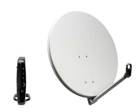
4 Introduction 1.2 Material Provided in the Box version
5 Introduction version
6 Introduction 1.3 Required Installation Tools version
7 Antenna Installation 2 Antenna Installation 2.1 Step 1: Choosing a Suitable Location Outdoors: Antenna & ilnb When setting up the antenna base, take into account the orientation of the antenna. Orientation data is provided by your Service Provider. The antenna must have a clear view towards the satellite (without any buildings, trees,... that may hinder the signal). To connect the ilnb to the Modem, use a coax cable. You can use the provided coax cable, or a coax cable with the same specifications as described in the Terminal Specifications available on the CD. The coax cable included in the box is 30 meters long. Indoors: Modem and computer Put the Modem indoors in a dry room and connect to: The antenna (with the coax cable); Your computer (with a network cable). Use the network cable provided in the box or a cable of your choice (for example if you need a longer cable to connect the modem to your computer); A wall outlet (with the power adapter provided in the box). Power adapter specifications: universal input range Volt, 50-60Hz. These steps are described further in this document. version
8 Antenna Installation 2.2 Step 2: Mounting the Antenna Pole Material you have to provide yourself A solid base for the antenna, made of concrete or firmly attached to a wall; An antenna pole. Antenna pole requirements The antenna pole must be installed on a solid base and made of galvanized steel; Minimum diameter: 45mm (60mm recommended); Maximum diameter: 70mm. When fixing the antenna pole to the base, use a spirit level to make sure the antenna pole stands in a vertical upright position. version
9 Antenna Installation 2.3 Step 3: Preparing the Masthead Unfold the feed arm and fix its position by tightening the two pre-mounted screws on the masthead. version
10 Antenna Installation 2.4 Step 4: Setting the Elevation Angle 1 Mount the elevation adjustment bolt onto the masthead. Do not yet tighten the four elevation bolts, as the elevation angle should be set first. version
11 Antenna Installation 2 Use the antenna pointing information provided by your Service Provider to look up the elevation angle that applies to your location, or to the city closest to your location. Using the elevation scale on the left side of the masthead, set the elevation angle to the value you have found in the antenna pointing information, by rotating the elevation adjustment bolt with the hex key. 3 When the elevation angle is set, tighten the four elevation bolts to fix the elevation angle. version
12 Antenna Installation 2.5 Step 5: Mounting the Antenna 1 Use the antenna pointing information provided by your Service Provider to look up the azimuth angle that applies to your location, or to the city closest to your location. Mount the masthead to the antenna pole, ensuring that the unfolded feed arm points to the azimuth value you have found in the antenna pointing information. Use a compass to verify. version
13 Antenna Installation 2 Secondly, mount the antenna dish onto the masthead. version
14 Antenna Installation 3 Thirdly, mount the ilnb clamp onto the feed arm. version
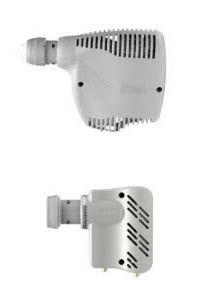
15 Antenna Installation 2.6 Step 6: Mounting the ilnb Ka-band ilnb If you have a Ka-band ilnb (ILB2210), mount it into the clamp. Ensure that the clasp at the bottom of the ilnb fits into the notch of the clamp. The two screws can be tightened. When finished, please proceed to Step 7. version
16 Antenna Installation Ku-band ilnb 1 If you have a Ku-band ilnb (ILB2110, ILB2120, ILB2140), mount it into the clamp. Do not yet tighten the two screws, as the polarization angle should be set first. version
17 Antenna Installation 2 Use the antenna pointing information provided by your Service Provider to look up the polarization angle that applies to your location, or to the city closest to your location. Identify the angle marker on the ilnb feedclamp as indicated in the figure below. The angle marker is in fact the line that separates the top and bottom part of the feedclamp. Using the polarization scale on the ilnb, set the polarization angle to the value you have found in the antenna pointing information. Examples for three values are shown in the figure below. version
18 Antenna Installation 3 When the polarization angle is set, tighten the two screws to fix the polarization angle. version
19 Antenna Installation 2.7 Step 7: Connecting the Equipment Preparing the Coax Cable The twin coax cable is delivered with two premounted waterproof connectors on one side. This is the outdoor end of the cable. The other side of the cable has no connectors attached yet, which allows the length of the cable to be reduced (e.g. if required for practical reasons). This is the indoor end of the cable. Execute the following steps to attach the F-connectors to the indoor end of the cable. You will need a cutter (and possibly pliers) to connect the F-connectors. 1 Strip the coax cable as shown below. Do not remove the aluminum foil or fold it back. version
20 Antenna Installation 2 Fold the wire shielding backwards over the cable jacket. 3 Cut away the plastic shield. Screw the F-connector to the wire by hand. 4 The result should resemble like the figure below: Repeat this procedure for the second F-connector. version
21 Antenna Installation Grounding the ilnb The grounding kit bag can be found in the modem box. You won t need all items contained in the grounding kit bag. Which items you actually have to use depends on your ilnb type. Ground your ilnb as indicated in the figures below. The masthead needs to be grounded according to local regulations. Consult with a licensed electrician if in any doubt ILB2210 and ILB2140 version
22 Antenna Installation ILB2110 and ILB Connecting the Modem to the ilnb Connect the modem to the ilnb. Make sure to use the premounted and waterproof outdoor connectors on the ilnb. The figure below shows the connection to a Ka-band ilnb. The connection to a Ku-band ilnb is similar. version
23 Antenna Installation Connecting the Modem to your Computer 1 Plug the network cable in the modem s and your computer s Ethernet ports. Use the network cable provided in the box or a cable of your choice. version
24 Antenna Installation 2 Connect the power adapter provided in the box to the modem and a wall outlet. The modem itself can be installed in three ways (as illustrated in the picture below): Wall mounted (Note: screws for wall mount installation are not included); Horizontal; Vertical (mounted on the included stand). version
 of the modem. Make sure the modem is turned on and properly connected to your computer.")
25 Terminal Installation 3 Terminal Installation Before you start: The procedure below assumes: - that your computer is DHCP enabled; - that you will connect a single computer to the modem. You need to access the GUI (Graphical User Interface) of the modem. Make sure the modem is turned on and properly connected to your computer. On your computer, start your internet browser (Internet Explorer, Chrome, Mozilla Firefox, Opera, Safari...). Type in the address bar of the browser and press Enter. The terminal installation page opens. version
26 Terminal Installation If the software version of your modem is not 2.2.x.y (where x and y can be any number), the installation procedure can slightly differ from what is described in this manual. The software version is shown on the installation page. Please contact your Service Provider in case of problems 3.1 Step 1: Select Outdoor Unit Select the outdoor unit type corresponding to your antenna size and ilnb and click to continue. (Note: the screenshot below is just an example) version
27 Terminal Installation 3.2 Step 2: Select Spot Beam Select the beam identifier corresponding to your location as indicated in the antenna pointing information provided by your Service Provider, and click screenshot below is just an example) to continue. (Note: the version
28 Terminal Installation 3.3 Step 3: Pointing your Antenna Do not stand in front of the ilnb of the antenna dish during pointing. Keep the space between the ilnb and the antenna dish clear Enabling Pointing Mode on the Modem If two pointing carriers have been pre-configured, keep the pre-selected carrier. If pointing fails during the procedure, you will need to repeat this step with the other pointing carrier. Click Point&Play Tool. Click pointed). to start the pointing procedure and proceed to the next section: Setting up the to skip the pointing procedure (use if the antenna was already correctly version
29 Terminal Installation Setting Up the Point&Play Tool Introduction The Point&Play tool helps you to point the antenna correctly. During the pointing procedure, the Point&Play tool can produce various sounds, each having a specific meaning described below. You will thus need to put on the headphone whenever needed during the pointing procedure. Ensure that the volume of the Point&Play tool is not set too loudly, otherwise damage to your hearing may occur. Possible tones are: - High uninterrupted tone (correct tone) The antenna points to the correct satellite and is receiving the strongest signal: you have the optimal pointing position. version
30 Terminal Installation - Medium or high interrupted tone The antenna points to the correct satellite but does not receive the strongest signal so far. As soon as you hear this tone, you are sure that the antenna points to the correct satellite. - Low uninterrupted tone The antenna is not pointing to a satellite or points to a wrong satellite. version
31 Terminal Installation Using the Point&Play Tool To use the Point&Play tool: 1 Remove the TX connector from the ilnb and connect it to the Point&Play tool. 2 Connect the earphone to the Point&Play tool. Make sure the Point&Play tool is still switched off. version
32 Terminal Installation Rough Pointing Vertical Pointing The correct elevation angle was already set during the installation of the antenna. Verify that the elevation angle of the masthead still corresponds to the value you have found in the antenna pointing information, and that it did not change during the assembly of the antenna (e.g. due to the weight of the antenna dish). Adjust if necessary (see section 2.4) Horizontal Pointing The correct azimuth angle was already set during the installation of the antenna. Verify that the azimuth angle still corresponds to the value you have found in the antenna pointing information, and that it did not change during the assembly of the antenna. Adjust if necessary (see section 2.5). Switch on the Point&Play tool by slowly turning the volume wheel until the green LED illuminates. Put on the earphone and adjust the volume if necessary. Now the actual pointing procedure can start. No Tone Check if the battery of the Point&Play tool is not dead. Since the correct elevation and azimuth angles have already been set, you should hear a high uninterrupted tone (see section ). If this is not the case, adjust the elevation and/or azimuth angles until you hear the highest possible continuous pitch tone (detection of the correct satellite). Make sure you position the antenna in the middle of this highest tone range. version
33 Terminal Installation If you do not hear a high pitch tone even after adjusting the azimuth and elevation angles, please refer to the Troubleshooting Guide available on the CD Optimize Vertical Pointing (Elevation) Important note: Whenever the procedure tells you to loosen a securing bolt or nut, make sure it is just loose enough to allow the corresponding element to move freely. 1 Loosen the four elevation bolts (two on either side of the masthead). version
34 Terminal Installation 2 Optimize the elevation setting by rotating the elevation adjustment bolt, using the included hex key, until the Point&Play tool produces the highest continuous pitch tone. 3 Secure the four elevation bolts in an alternating manner to keep the highest pitch tone. version
35 Terminal Installation Optimize Horizontal Pointing (Azimuth) 1 Loosen the four azimuth bolts (two at the top of the masthead, two at the bottom). 2 Optimize the azimuth setting by rotating the azimuth fine adjust bolt, using the included hex key, until the Point&Play tool produces the highest continuous pitch tone. version
36 Terminal Installation 3 Secure the four azimuth bolts in an alternating manner to keep the highest pitch tone Checking the Pointing Perform the following checks to make sure the antenna will resist external movements (wind...): 1 Make sure all bolts are tightly secured. 2 Briefly place your hand between the ilnb and the dish. As soon as you remove your hand, you need to hear the continuous high pitch tone again. version


37 Terminal Installation 3 Apply some pressure on the antenna to make the edges move about 3cm on the left hand side, right hand side and at the top, then release it. If the antenna is still pointed correctly, you will hear the high pitch tone again. If not, repeat the pointing procedure. When the antenna is correctly pointed, the message Correct satellite pointed optimally appears on the screen of your computer, as shown below. You can now proceed to section When the antenna is not optimally pointed, the message Correct satellite not pointed optimally is displayed on the screen of your computer, as shown in the following picture. Repeat the pointing procedure. If the problem persists, refer to the Troubleshooting Guide on the CD. version
38 Terminal Installation Finishing the Pointing 1 Turn off the Point&Play tool 2 Remove the TX cable from the Point&Play tool and reconnect it to the ilnb. 3 Use tie-wraps to attach the cables to the feed arm. Make sure to leave some slack on the cables. 4 Back at your computer, in the status page of the modem, click version

39 Terminal Installation 3.4 Step 4: Software Download The modem continuously checks for software updates. If the software is still up to date, this step is skipped automatically. You can proceed with step 5: Validation of the Installation. If a newer software version is available, download will start automatically. - Once the download is complete, the new software is written to flash memory. - The modem reboots automatically. Now you can proceed to Step 5: Validation of the Installation. You may need to refresh the page of your browser manually after the reboot. version
40 Terminal Installation 3.5 Step 5: Validation of the Installation When step 4 is completed, the following screen is shown: The modem will now check if the quality of the installation needs to be validated. This depends on your Service Provider. If validation of your terminal installation is not required by your Service Provider, this step is completed automatically and the terminal installation is finished. You can proceed to section 3.6 Finish Installation. If validation of your terminal installation is required by your Service Provider, please proceed with this section and execute the following sequence of tasks. version

41 Terminal Installation Accept Disclaimer As this validation procedure involves sensitive information such as geographical location of the terminal which is subject to legal restrictions, a disclaimer is presented. Please read the disclaimer message and indicate your acceptance by clicking Enter Location The validation of your installation is based on the geographical location of your terminal. There are 2 options to enter this information: Option 1: enter your address; Option 2: enter your location s latitude and longitude Option 1: Enter your Address Enter the address where the terminal is located. At a minimum, your city and country are required. version


42 Terminal Installation A list of one or more matching locations is displayed. Select your address from the list to view your location on a map. If your address is not listed or no results are displayed, refer to the Troubleshooting Guide on the CD. version
43 Terminal Installation The map is used to show the area of the selected location. Zooming in or out is not possible. Click to accept and proceed. If this is not your location, refer to the Troubleshooting Guide on the CD Option 2: Enter Latitude and Longitude Enter your location s latitude and longitude. These values should be entered in degrees, minutes and seconds notation or in decimal form (using a dot as a separator). Positive latitude = NORTH, positive longitude = EAST. This option can be used in case Option 1 fails. No map is displayed when latitude or longitude values are entered using Option 2. version

44 Terminal Installation Click to continue or to return to the previous screen Validation Once the location is confirmed, the validation begins. When validation is successful, click to proceed. If validation fails, please refer to the Troubleshooting Guide on the CD. version
45 Terminal Installation 3.6 Finish Installation If validation was not required by your Service Provider, the following screen is shown. Click to go to the Status Page. If validation was required by your Service Provider and it has been successfully completed, the Status Page is already shown. version
.")
46 Terminal Installation The terminal is ready for operation and all LED indicators on the status page are green. You are now ready to surf the internet. On-line registration may be required. Please check with your Service Provider. Please refer to the MDM2200 User Manual, describing the features and the web interface of the modem (available on the CD included in the box). In case of problems, please refer to the Troubleshooting Guide (available on the CD included in the box). version
47 Annex: Restart Installation 4 Annex: Restart Installation In some conditions (for example when moving the antenna to another location or upon request by your Service Provider), restarting the installation procedure is required. Select Terminal Installation in the left menu pane. Click to restart the complete installation procedure. Follow the steps as described in section 3 Terminal Installation. During the installation procedure, the terminal will not be operational. version
75cm ODU/SurfBeam 2 Point and Peak Job Aid
 Summary This Job Aid covers: 75cm ODU/SurfBeam 2 Point and Peak Job Aid Preparing the Antenna for Pointing and Peaking Configure the SurfBeam 2 Modem and 75cm TRIA Point Elevation Set the Skew Point Azimuth
2009 ODU Point and Peak Job Aid
 Summary This Job Aid covers: Preparing the Antenna for Pointing and Peaking Point Elevation Set the Skew Point Azimuth Peak Azimuth Peak Elevation Push/Pull Test This Job Aid supports all Technician audiences.
2005 ODU Point & Peak Job Aid
 Summary This Job Aid covers: Preparing the Antenna for Pointing and Peaking Point Elevation Set the Skew Point Azimuth Peak Azimuth Peak Elevation Push/Pull Test This Job Aid supports all Technician audiences.
Paradigm. Connect100 Installation Guide
 Paradigm GX Connect100 Installation Guide Paradigm GX Safe Use WARNING Radiation Hazard. Transmitter power levels are sufficient to cause blindness or other serious injury to body tissue. Do not power
3 GHz Carrier Backhaul Radio. Model: AF-3X. Tel: +44 (0) Fax: +44 (0) LINK GPS MGMT DATA DATA
 Fax: +44 (0) LINK GPS MGMT DATA DATA") LINK GPS MGMT DATA DATA MGMT GPS LINK 3 GHz Carrier Backhaul Radio Model: AF-3X LINK GPS MGMT DATA 3 GHz Carrier Backhaul Radio Model: AF-3X LINK GPS MGMT DATA DATA MGMT GPS LINK Introduction Thank you
LINK GPS MGMT DATA DATA MGMT GPS LINK 3 GHz Carrier Backhaul Radio Model: AF-3X LINK GPS MGMT DATA 3 GHz Carrier Backhaul Radio Model: AF-3X LINK GPS MGMT DATA DATA MGMT GPS LINK Introduction Thank you
LINK GPS MGMT DATA. 4 GHz Licensed Backhaul Radio DATA MGMT GPS. Model: AF-4X LINK
 LINK GPS MGMT DATA DATA MGMT GPS LINK 4 GHz Licensed Backhaul Radio Model: AF-4X 4 GHz Licensed Backhaul Radio Model: AF-4X LINK GPS MGMT DATA DATA MGMT GPS LINK Introduction Thank you for purchasing the
HFp. User s Guide. Vertical. entenna. 7 MHz 30 MHz Amateur Radio Antenna Plus 6-Meters
 User s Guide HFp Vertical 7 MHz 30 MHz Amateur Radio Antenna Plus 6-Meters The Ventenna Co. LLC P.O. Box 2998, Citrus Heights, CA, 956 www.ventenna.com entenna Table of Contents The HFp Antenna -------------------------------------------------------------------
Quick Start Guide. Contents
 1 Quick Start Guide Contents Powering on the Machine Login/Password Entry Jaw Set Up High Security Cut by Code High Security Jaw Set Up Edge Cut Cut by Code Edge Cut Cut by Decode Cutter Replacement Tracer
Installation Manual Mobile Integration System
 Installation Manual Mobile Integration System Table of Contents Kit Contents... 2 Overview... 3 Installation Instructions... 6 Power up... 12 Test the System... 13 Beam Coverage... 14 Trouble Shooting
Installation Guide. Hiltron Motorized Antenna Mount HMAM
 HMAM_Install_A.doc Page 1 of 20 Installation Guide for Hiltron Motorized Antenna Mount HMAM HMAM_Install_A.doc Page 2 of 20 Table of Contents 1 Overview...3 2 Unpacking and Inspection...3 3 Contents of
Instruction Manual for 98cm Elliptical Ka Antenna
 Instruction Manual for 98cm Elliptical Ka Antenna 98cm WB Issue 03 Caution This instruction leaflet will assist you in the correct installation of the product. Read it prior to starting any installation
Yara Water Solution. Installation Guide. Product summary: - Included components - Tools for setup - Installation overview
 Yara Water Solution Installation Guide Product summary: - Included components - Tools for setup - Installation overview Step by step installation guide: - Mounting the Base Station - Preparing the field
Antenna Pointing Guide
 Antenna Pointing Guide 1039429-0001 Revision B September 10, 2013 11717 Exploration Lane, Germantown, MD 20876 Phone (301) 428-5500 Fax (301) 428-1868/2830 Copyright 2013 Hughes Network Systems, LLC All
QDV120 Operation and Pointing manual
 QDV120 Operation and Pointing manual MPAD1 Plus OP-080316-E1 page 1 Contents Item Description Page 1.0 Health and Safety for Operators and Installation Staff 3 2.0 Transit case Reflector/Mount/BUC/LNB
SELFSAT-H10D. What is SELFSAT-H10D? Warning!!! Safety Instructions
 SELFSAT-H0D What is SELFSAT-H0D? SELFSAT-H0D is a Horn Array Type Satellite Antenna with Dual Linear Polarization, it can receive signal from major Satellites and would replace a normal former Parabolic
.84M Ku-Band Rx/O Antenna System
 4096-644 Revision A May 9, 2003 ASSEMBLY MANUAL.84M Ku-Band Rx/O Antenna System PRODELIN CORPORATION 1500 PRODELIN DRIVE NEWTON, NC 28658 .84M Ku-Band Rx/O Antenna System A ORIGINAL RELEASE 5/9/2003 A.Hahn
I n s t a l l a t i o n M a n u a l. T E D P r o L i t e A B C. f o r. Shop for The Energy Detective products online at: Rev 3.
 Rev 3.5 I n s t a l l a t i o n M a n u a l f o r T E D P r o H o m e T E D P r o L i t e A B C Shop for The Energy Detective products online at: 1.877.766.5412 IMPORTANT: The installation of your TED
11 GHz FDD Licensed Backhaul Radio. Model: AF 11FX
 11 GHz FDD Licensed Backhaul Radio Model: AF 11FX 11 GHz FDD Licensed Backhaul Radio Model: AF 11FX Introduction Thank you for purchasing the Ubiquiti Networks airfiber AF 11FX. This Quick Start Guide
IG-2500 OPERATIONS GROUND CONTROL Updated Wednesday, October 02, 2002
 IG-2500 OPERATIONS GROUND CONTROL Updated Wednesday, October 02, 2002 CONVENTIONS USED IN THIS GUIDE These safety alert symbols are used to alert about hazards or hazardous situations that can result in
HN9200 Satellite Modem Installation Guide
 HN9200 Satellite Modem Installation Guide 1038622-0001 Revision B March 2, 2011 Copyright 2010-2011 Hughes Network Systems, LLC All rights reserved. This publication and its contents are proprietary to
Installing the Hughes BGAN Remote Antenna
 Installing the Hughes BGAN Remote Antenna Product description BGAN Remote Antenna The Hughes BGAN Remote Antenna (HNS Part No. 9501286-0001) is designed to be permanently installed with the Basic Fixed
SolidRF SOHO Tri-Band Cell Phone Signal Booster for GSM, GPRS, CDMA 3G and Verizon 4G LTE. 700 MHz(Band 13) / 850 MHz / 1900 MHz ONLY
 / 850 MHz / 1900 MHz ONLY") SolidRF SOHO Tri-Band Cell Phone Signal Booster for GSM, GPRS, CDMA 3G and Verizon 4G LTE 700 MHz(Band 13) / 850 MHz / 1900 MHz ONLY If you have any questions or concerns when installing or operating your
SolidRF SOHO Tri-Band Cell Phone Signal Booster for GSM, GPRS, CDMA 3G and Verizon 4G LTE 700 MHz(Band 13) / 850 MHz / 1900 MHz ONLY If you have any questions or concerns when installing or operating your
Ground System Training Department
 Module 7: IPSTAR Uplink Access Test (IUAT) Ground System Training Department 2012-03-Standard (iuat1.14)-uti-101 THAICOM Public Company Limited Module Objectives At the end of the module the participant
Underwater GPS User Manual
 Underwater GPS Document number W-DN-17002-3 Project Classification - Rev Prepared by Checked by Approved by Short description 1 2017-08-03 T. Trøite O. Skisland T. Trøite Initial 2 2017-08-04 T. Trøite
The DesignaKnit USB E6000 Link 1 & 2
 The DesignaKnit USB E6000 Link 1 & 2 for the Passap / Pfaff Electronic 6000 USB E6000 Link 1 USB E6000 Link 2 What these links do The USB E6000 Link 1 enables downloading of stitch patterns from DesignaKnit
Installation Guide Flat Panel Antenna Mounting Kit For
 Installation Guide Flat Panel Antenna Mounting Kit For 103670-1 495R Billerica Ave. North Billerica, MA 01862 USA Tel (978)459-8800 fax (978)459-3310 / 8814 Email: sales@radiowaves.com www.radiowaves.com
User Manual. This User Manual will guide you through the steps to set up your Spike and take measurements.
 User Manual (of Spike ios version 1.14.6 and Android version 1.7.2) This User Manual will guide you through the steps to set up your Spike and take measurements. 1 Mounting Your Spike 5 2 Installing the
HFp. User s Guide. Vertical. entenna. 7 MHz 54 MHz Amateur Radio Antenna. The Ventenna Co. LLC P.O. Box 227 Huston, ID
 User s Guide HFp Vertical 7 MHz 54 MHz Amateur Radio Antenna The Ventenna Co. LLC P.O. Box 227 Huston, ID 83630 www.ventenna.com entenna Table of Contents The HFp Antenna -------------------------------------------------------------------
Yagi and Omni Antennas Installation Manual
 Yagi and Omni Antennas Installation Manual 25500445 Rev. A0 0218 Printed in U.S.A. Copyright 2018 Federal Signal Corporation Limited Warranty This product is subject to and covered by a limited warranty,
I n s ta l l at i o n M a n u a l f o r T E D P r o H o m e T E D P r o L i t e A B C Rev 4.0
 I n s t a l l a t i o n M a n u a l f o r T E D P r o H o m e T E D P r o L i t e A B C Rev 4.0 IMPORTANT: The installation of your TED Pro Home system is a several-step process. The 1st step is the installation
Super Sky Surfer 2000 Assembly Instructions
 Super Sky Surfer 2000 Assembly Instructions Note: Plug and Play version of the Sky Surfer comes with fuselage pre-glued and motor/servos installed. If you wish to route antennas or wires through the tail,
HT1000 Satellite Modem Installation Guide
 HT1000 Satellite Modem Installation Guide 1039110-0001 Revision A October 17, 2012 11717 Exploration Lane, Germantown, MD 20876 Phone (301) 428-5500 Fax (301) 428-1868/2830 Copyright 2012 Hughes Network
Aluminum Sprinter Rack Installation
 INSTALLATION INSTRUCTIONS MyGlassTruck.com Division of Demountable Concepts, Inc Aluminum MyGlassTruck.Com Demountable Concepts, Inc. 200 Acorn Rd. Glassboro, NJ 08028 800.254.3643 toll free 856.863.0900
DRAFT. Sudden Ionospheric Disturbance (SID) Antenna Manual. Stanford Solar Center Stanford University Version 2.0
 Antenna Manual. Stanford Solar Center Stanford University Version 2.0") DRAFT Sudden Ionospheric Disturbance (SID) Antenna Manual Stanford Solar Center Stanford University Version 2.0 Construction and maintenance of your SID Monitor s Antenna TABLE OF CONTENTS DOCUMENT STATUS...2
DRAFT Sudden Ionospheric Disturbance (SID) Antenna Manual Stanford Solar Center Stanford University Version 2.0 Construction and maintenance of your SID Monitor s Antenna TABLE OF CONTENTS DOCUMENT STATUS...2
Remarks: Before Installation, please read the instruction carefully.
 60 cm antenna Z24A60T37301 Remarks: Before Installation, please read the instruction carefully. This instruction book is for the installation of 0.6m ultra-high performance microwave antenna. Installation,
Cisco Aironet 2.4-GHz/5-GHz 8-dBi Directional Antenna (AIR-ANT2588P3M-N)
") Cisco Aironet.4-GHz/5-GHz 8-dBi Directional Antenna (AIR-ANT588P3M-N) This document outlines the specifications for the Cisco Aironet AIR-ANT588P3M-N.4/5-GHz 8-dBi 3-Port Directional Antenna with N-connectors
Cisco Aironet.4-GHz/5-GHz 8-dBi Directional Antenna (AIR-ANT588P3M-N) This document outlines the specifications for the Cisco Aironet AIR-ANT588P3M-N.4/5-GHz 8-dBi 3-Port Directional Antenna with N-connectors
Mounting and Alignment Overview
 CHAPTER 3 This chapter provides an overview of bridge mounting and antenna alignment. The following sections are included in this chapter: Mounting the Bridge, page 3-2 Mounting Hardware, page 3-2 Bridge
BL-ER-P Ethernet Radio Unit for Pedestal Installation Guide
 Assemble the Antenna Riser 1. Remove the antenna riser assembly and the antenna from its packaging. 2. Remove the plastic cap, the nut, and the lock washer from the stem of the antenna. 3. Put the stem
ABM International, Inc.
 ABM International, Inc. Lightning Stitch required 1 1.0: Parts List head and motor assembly (Qty. 1) Reel stand (Qty. 1) Needle bar frame clamp (Qty. 1) Motor drive (Qty. 1) 2 Cable harness with bracket
ABM International, Inc. Navigator Assembly Manual
 ABM International, Inc. 1 1.0: Parts List Tablet (Qty. 1) Tablet mount (Qty. 1) NOTE: Mount may appear and operate different then image below Control Box (Qty. 1) Motor Power Supply (Qty. 1) 2 X-axis motor
LIGHT BEAM ANTENNA MaxRange Antenna Series Assembly Instructions MaxRange Plus Digital / High Definition Television Antennas
 LIGHT BEAM ANTENNA MaxRange Antenna Series Assembly Instructions MaxRange Plus Digital / High Definition Television Antennas Assembly Instructions 1 MaxRange Plus Antenna These instructions will lead you
Installation and Assembly - Universal Articulating Swivel Double-Arm for 42" - 60" Plasma Screens
 Installation and Assembly - Universal Articulating Swivel Double-Arm for 42" - 60" Plasma Screens Models: PLAV 70-UNL, PLAV 70-UNL-S PLAV 70-UNLP, PLAV 70-UNLP-S R This product is UL Listed. It must be
Standard Operating Procedure
 RIT MULTIDISCIPLINARY SENIOR DESIGN 2010 Standard Operating Procedure Baja Water Propulsion Test Stand This SOP specifies how to assemble, use, troubleshoot, and disassemble the water propulsion system
Model 6025 Single-Boom
 Log Periodic FM Broadcast Antenna Model 6025 Single-Boom Instruction Manual Installation, Operation, & Maintenance Congratulations! Thank you for purchasing one of the finest FM broadcast antennas on the
LIGHT BEAM ANTENNA MaxRange Antenna Series Assembly Instructions MaxRange Ultra Digital / High Definition Television Antennas
 LIGHT BEAM ANTENNA MaxRange Antenna Series Assembly Instructions MaxRange Ultra Digital / High Definition Television Antennas Assembly Instructions 1 MaxRange Ultra Antenna These instructions will lead
Installation Instructions TMW Antenna Tower Mount for 4ft (1.2m) Antennas.
 Antennas.") Description The following pages show the steps required to assembly and fit the antenna mount to a vertical tower pipe of diameter 48 to 115 mm (1.9 to 4.5"). This mount provides ±20 azimuth or ±15 elevation
Description The following pages show the steps required to assembly and fit the antenna mount to a vertical tower pipe of diameter 48 to 115 mm (1.9 to 4.5"). This mount provides ±20 azimuth or ±15 elevation
The Queen Quilter Professional Quilters Kit Frame
 The Queen Quilter Professional Quilters Kit Frame Assembly Instructions Table of Contents: Before you begin......................... Pg. 2 Wood parts............................. Pg. 3 Hardware..............................
1.2 METER SERIES 1130 Rx/O ANTENNA SYSTEM
 REVISION H April 20, 2016 ASSEMBLY MANUAL 1.2 METER SERIES 1130 Rx/O ANTENNA SYSTEM General Dynamics SATCOM Technologies 1700 Cable Drive NE Conover NC 28613 USA Phone 770-689-2040 www.gdsatcom.com 1.2
GC-1032 Metal Detector OWNER S MANUAL
 GC-1032 Metal Detector OWNER S MANUAL 1 With your GC-1032 metal detector, you can hunt for coins, relics, jewelry, gold, and silver just about anywhere. The detector comes with high sensitivity and strong
Technical publication. Path alignment and cross polarization procedure for parabolic microwave antennas
 Technical publication Path alignment and cross polarization procedure for parabolic microwave antennas Contents 1.0 Introduction 3 2.0 Path alignment procedure 3 2.1 Setting azimuth marker 3 2.2 Test equipment
User Instructions Multiline Otter Scoreboard Caddy Assembly
 List of parts: User Instructions Multiline Otter Scoreboard Caddy Assembly Single Caddy Double Caddy 1 1 Base assembly with attached wheels 2 4 1 1 2 4 4 8 10 20 12 Uprights (60 or 74 aluminum extrusion)
The Instructions should be read, prior to commencing the installation, failure to follow these instructions will void your warranty.
 Low Voltage System The Platinum Low Voltage lighting system can power up to 120 candle pods depending on the length of cables used during the installation this can reduce the number of pods to 24 per outlet
INDEX. Accessories and Components System Unit and Joystick Assembly and Charging the Battery Using with LED System...
 USER GUIDE INDEX Accessories and Components... 4 System Unit and Joystick... 6 Assembly and Charging the Battery... 9 Using with LED System... 11 What is Ground Setting and How It Is Done... 14 Ground
Installation Job Aid (English) for Avaya WLAN 8100 series- WLAN AP 8120 with External Antenna
 for Avaya WLAN 8100 series- WLAN AP 8120 with External Antenna") Release 3.0 NN47251-311 Issue 02.01 June 2014 Installation Job Aid (English) for Avaya WLAN 8100 series- WLAN AP 8120 with External Antenna How to get help To access the complete range of services and
Release 3.0 NN47251-311 Issue 02.01 June 2014 Installation Job Aid (English) for Avaya WLAN 8100 series- WLAN AP 8120 with External Antenna How to get help To access the complete range of services and
Specifications Sheet: PRIME FOCUS MESH DISH KIT 1.2 Meter DISH
 Specifications Sheet: PRIME FOCUS MESH DISH KIT 1.2 Meter DISH Available F/D: 0.35 / 0.4 / 0.45 / 0.5 (Example Picture: 1.2 Meter dish (6mm mesh) 1M2_KIT_SPEC RF HAMDESIGN www.rfhamdesign.com This 8-Rib
GPSR400 Quick Start Guide
 GPSR400 Quick Start Guide Rev. 6 Introduction Microlab s digital GPS repeater system can be used for cellular communications UTC synchronization for locations where the GPS signals are not readily available.
Sutron SatLink2 Troubleshooting Instructions
 Sutron SatLink2 Troubleshooting Instructions A. SatLink2 (SL2) symptoms: Missing or partial data on LRGS (check DIS-MSG for frequency and EIRP; use HDR DCP Message header list. B. Equipment and tools needed:
Remarks: Before Installation, please read the instruction carefully.
 30 cm antenna Z24A30T37301 Remarks: Before Installation, please read the instruction carefully. This instruction book is for the installation of 0.3m ultra-high performance microwave antenna. Installation,
15MM LINEAR MOTION SYSTEM
 222fg 15MM LINEAR MOTION SYSTEM September 20, 2017 15mm Linear Motion System Copyright 2017 REV Robotics, LLC 1 TABLE OF CONTENTS 1 INTRODUCTION... 3 2 ASSEMBLY INSTRUCTIONS... 4 3 How to drive Linear
MESA-HPX. Assembly and Installation Manual. w/appendix A for Prodelin Antenna. 901-Manual-MESA-HPX
 MESA-HPX Assembly and Installation Manual w/appendix A for Prodelin Antenna 901-Manual-MESA-HPX Rev 30 March 2011 2 INDEX Installation Cautions 4 Installation Pole Height Orientation of the Mount on the
1. ASSEMBLING THE PCB 2. FLASH THE ZIP LEDs 3. BUILDING THE WHEELS
 V1.0 :MOVE The Kitronik :MOVE mini for the BBC micro:bit provides an introduction to robotics. The :MOVE mini is a 2 wheeled robot, suitable for both remote control and autonomous operation. A range of
Bipedinno. 12-DOF Waist-high Robot
 Bipedinno 12-DOF Waist-high Robot Instruction Manual Version 1.18 Trademark Innovati,, and BASIC Commander, are registered trademarks of Innovati Inc. InnoBASIC and cmdbus are trademarks of Innovati Inc.
Assembly Guide Robokits India
 Robotic Arm 5 DOF Assembly Guide Robokits India info@robokits.co.in Robokits World http://www.robokitsworld.com http://www.robokitsworld.com Page 1 Overview : 5 DOF Robotic Arm from Robokits is a robotic
Lumber Smith. Assembly Manual. If you are having problems assembling the saw and need assistance, please contact us at:
 Lumber Smith Assembly Manual If you are having problems assembling the saw and need assistance, please contact us at: 804-577-7398 info@lumbersmith.com 1 Step 1 Safety Carefully read the Owners Manual.
Cisco Aironet 13.5-dBi Yagi Mast Mount Antenna (AIR-ANT1949)
") Cisco Aironet 13.5-dBi Yagi Mast Mount Antenna (AIR-ANT1949) Overview This document describes the 13.5-dBi Yagi mast mount antenna and provides instructions for mounting it. The antenna operates in the
Cisco Aironet 13.5-dBi Yagi Mast Mount Antenna (AIR-ANT1949) Overview This document describes the 13.5-dBi Yagi mast mount antenna and provides instructions for mounting it. The antenna operates in the
Video Wall Installation Instructions 2W X 3H, 3W X 3H
 Video Wall Installation Instructions 2W X 3H, 3W X 3H www.microndisplaysolutions.com Table of Contents Important Safety Instructions... 3 Configuration... 4 Package Contents, included and optional items...
Yara Water Solution. Installation Guide. Product summary: - Included components - Tools for setup - Installation overview
 Yara Water Solution Installation Guide Product summary: - Included components - Tools for setup - Installation overview Step by step installation guide: - Mounting the Base Station - Preparing the field
Quick Start Guide. Version: 1.0 F/W: V1.2.0_RC1b. Date: December 11, 2017
 VigorAP 920R Series Ruggedized Outdoor AP with Extreme 802.11ac Power Warranty Quick Start Guide Version: 1.0 F/W: V1.2.0_RC1b Date: December 11, 2017 We warrant to the original end user (purchaser) that
Installation & Quick Start Guide CLB2000 Class B AIS Transponder
 Installation & Quick Start Guide CLB2000 Class B AIS Transponder QUICK START CLB2000 - VR1.01 1. Introduction Congratulations on the purchase of your CLB2000 Class B AIS Transponder. It is recommended
Blackout Fan Kits with Breathable Wall Light Traps
 Blackout Fan Kits with Breathable Wall Light Traps 2018 Growers Supply All Rights Reserved. Reproduction is prohibited without permission. Maintain controlled airflow without sacrificing blackout environments.
LinkAlign-60RPT Set-up and Operation Manual
 LinkAlign-60RPT Set-up and Operation Manual LinkAlign Setup and Operation Proprietary, Nextmove Technologies Page 1 LinkAlign Setup and Operation Proprietary, Nextmove Technologies Page 2 Description of
Installation and Assembly - Universal Articulating Swivel Double-Arm for 42" - 60" Plasma Screens
 Installation and Assembly - Universal Articulating Swivel Double-Arm for 42" - 60" Plasma Screens Models: PLAV 70-UNL, PLAV 70-UNL-S PLAV 70-UNLP, PLAV 70-UNLP-S R This product is UL Listed. It must be
Circularly Polarized FM Broadcast Antenna
 Circularly Polarized FM Broadcast Antenna Versa2une (SLV) 6 to 12-bay, full-wave-spaced Instruction Manual Installation, Operation, & Maintenance Congratulations! Thank you for purchasing one of the finest
Printer Software Guide
 Printer Software Guide (For Canon CP Printer Solution Disk Version 4) Macintosh 1 Contents Safety Precautions...3 Read This First...4 About the Manuals...4 Printing Flow Diagram...5 Printing...7 Starting
Plug-n-Show Stake Down Pixel Tree Kit 16 strips of 25 pixels Assembly Instructions
 www.lightorama.com Plug-n-Show Stake Down Pixel Tree Kit 16 strips of 25 pixels Assembly Instructions Read all instructions before you start Kit assembly! STEP 1. Check that all parts are included Parts
Spiderbeam Balun Construction Guide
 BALUN CONSTRUCTION GUIDE Ver. 1.0 1 The components of the Balun Kit are in a plastic bag. Most of the components are inside the plastic case of the balun. The aluminum U-profile and the RG-142 Teflon Coax
Breathable Wall Light Traps & Blackout Fan & Shutter Kits
 Breathable Wall Light Traps & Blackout Fan & Shutter Kits 2017 Growers Supply All Rights Reserved. Reproduction is prohibited without permission. Maintain controlled airflow without sacrificing blackout
75 cm ODU (VS1300) Assembly Job Aid
 Assembly Job Aid") Summary This Job Aid covers: Verify AZ/EL Assembly Alignment Antenna Back Bracket Assembly Transport On Site Assembly This Job Aid supports all Technician audiences. This job aid covers the VS1200 ODU
Summary This Job Aid covers: Verify AZ/EL Assembly Alignment Antenna Back Bracket Assembly Transport On Site Assembly This Job Aid supports all Technician audiences. This job aid covers the VS1200 ODU
Installing the 3 Indexer: PRS Standard Tools
 888-680-4466 ShopBotTools.com Installing the 3 Indexer: PRS Standard Tools Copyright 2016 ShopBot Tools, Inc. page 1 Copyright 2016 ShopBot Tools, Inc. page 2 Table of Contents Route Cable into Box...5
The DesignaKnit USB Brotherlink 5
 The DesignaKnit USB Brotherlink 5 for Brother electronic machines What this link does Uploading and downloading patterns to the KH930, KH940, KH950i, KH965i, and KH970 knitting machines. Interactive knitting
Brochure Includes: Set-up Instructions Operating Instructions Parts List Fundamentals of Drill Sharpening. Patent 3,952,459
 Patent 3,952,459 Brochure Includes: Set-up Instructions Operating Instructions Parts List Fundamentals of Drill Sharpening Accurately Sharpens most drills bits. Now, with this one low-cost, simple machine,
87.5 TO MHz BAND II 2 WAY 4.8dBi STACKED DIPOLE ANTENNA
 87.5 TO 108.0 MHz BAND II 2 WAY 4.8dBi STACKED DIPOLE ANTENNA 1. INTRODUCTION 3 1.1. GENERAL INFORMATION 3 1.2. UNPACKING AND CHECKING 3 1.3. WARRANTY 3 1.4. USER SAFETY RESPONSIBILITY 4 1.5. INSTALLATION
Powermatic Model 31A Combination Belt-Disk Sander
 OPERATING PROCEDURE FOR: Powermatic Model 31A Combination Belt-Disk Sander INTRODUCTION: The combination belt-disk sander is used to sand the edges of boards. It can be used to smooth the edge or to remove
Installation Instructions
 Installation Instructions For 4 foot / 1.2m Diameter Ultra-high Performance Antenna Model ADxxG-4-T2 Before Installation, please read the instructions carefully. This instruction guide covers the installation
Adjusting 45 Compass Hardware Including 4-Point
 Adjusting 45 Compass Hardware Including 4-Point Compass Hardware - US Patent No. 7,104,610 & 7,891,739 Apparatus for Mounting a Wheelchair Back Quick Release Fixed 4-Point The information in this manual
C-COM Satellite Systems Inc. Page 1 of 39
 Page 1 of 39 inetvu Fly-75V & Fly-98G/H/V & Fly-981 User Manual The inetvu brand and logo are registered trademarks of C-COM Satellite Systems, Inc. Copyright 2006 C-COM Satellite Systems, Inc. 1-877-iNetVu6
Pole Mount Installation Guide
 Pole Mount Installation Guide (No Fine Adjustment) 495R Billerica Ave. North Billerica, MA 01862 USA Tel (978)459-8800 fax (978)459-3310 / 8814 Email: sales@radiowaves.com www.radiowaves.com IMPORTANT!
MANUAL STANDARD. YAGI ELEMENTS 6-20m. Rev. 1.10
 MANUAL STANDARD YAGI 2-3-4-6 ELEMENTS 6-20m Rev. 1.10 1 INTRODUCTION UltraBeam produced its first antenna in 2008. Since then there was a progressive and continuous improvement in design and manufacturing
* * APPLICABLE MODELS: 2014 > MAZDA 3
 PART NUMBER: 0000 8C L46 GENUINE ACCESSORIES INSTALLATION INSTRUCTIONS Rev. AAA *550-0604-000* APPLICABLE MODELS: 204 > MAZDA 3 REQUIRED COMPONENTS: ITEM QTY DESCRIPTION Usage Chart MIRROR ASSEMBLY: Mirror
NOTE: Top section pole (Q) is packed INSIDE bottom section pole (S)
 is packed INSIDE bottom section pole (S)") Form 0905-0 Instructions and Parts List TM- Mini Castle (modified) MARTIN SAFETY SYSTEM NOTES: () A complete system is packed in two boxes post box and house box. House box contains hardware for both post
Form 0905-0 Instructions and Parts List TM- Mini Castle (modified) MARTIN SAFETY SYSTEM NOTES: () A complete system is packed in two boxes post box and house box. House box contains hardware for both post
SpeedTouch 190. Setup and User s Guide. SIP Gateway. Release R1.0
 SpeedTouch 190 SIP Gateway Setup and User s Guide Release R1.0 SpeedTouch 190 Setup and User s Guide Release R1.0 Status v1.0 Reference E-DOC-CTC-20040401-0004 Short Title Setup and User s Guide ST190
F10I-EGSM Single System
 F10I-EGSM Single System 1 Table of contents How it works... 3 Package contents... 4 Troubleshooting... 14 Specifications... 15 Product Warranty... 16 Safety Warnings... 17 2 How it works Huaptec F10I-EGSM
BUMP GATE FITTING INSTRUCTIONS.
 1 BUMP GATE FITTING INSTRUCTIONS. HEAVY DUTY MODEL FOR STEEL POSTS. Hinge post Lock post Bump arms Two-way lock Thank you for purchasing a Bump Gate. This device will provide you with many years of good
FUNCTIONAL DESCRIPTION
 FUNCTIONAL DESCRIPTION NOTE: The information contained in this Instruction Manual is designed to assist you in the safe operation and maintenance of the power tool. Some illustrations in this Instruction
COFDM Multifunctional Receiver Operation Instructions
 COFDM Multifunctional Receiver Operation Instructions Chapter Ⅰ (1) stand a good receiving antenna. Sucker whip antenna on the outside or the roof as possible, try to rod-shaped antenna mounted on the
Blackout Fan Kit with Breathable Wall Light Trap
 Blackout Fan Kit with Breathable Wall Light Trap 2018 Growers Supply All Rights Reserved. Reproduction is prohibited without permission. Maintain controlled airflow without sacrificing blackout environments.
Castle Frame Assembly Table AT-8. Diagnostics Manual. Castle, Inc. Petaluma, CA
 Castle Frame Assembly Table AT-8 Diagnostics Manual Castle, Inc. Petaluma, CA 800-282-8338 Solutions Index Adjusting the Tabletop.. 8.01 Adjusting the Fence... 8.02 Aligning the Arm... 8.10 Adjusting Bracket..
Operators Manual (Manual A)
") CD201 SINGLE COLUMN CARD DISPENSER Operators Manual (Manual A) Contents A1 Scope... 1 A2 Specifications... 1 A3 Installation... 2 3.1 Unpacking and inspection... 2 3.2 Opening and closing the door... 2
CD201 SINGLE COLUMN CARD DISPENSER Operators Manual (Manual A) Contents A1 Scope... 1 A2 Specifications... 1 A3 Installation... 2 3.1 Unpacking and inspection... 2 3.2 Opening and closing the door... 2
Greenhouse Assembly Instructions
 Greenhouse Assembly Instructions Our Help Line provides support and advice to customers of Summer Garden Buildings after ordering. For advice before you buy you can phone us free 7 days a week on 0800
BRU-100 Physical Installation
 APPENDIX B BRU-100 In This Appendix: Warnings and Cautions, page 50, page 51 Check List, page 57 This appendix provides guidance for the physical installation of the BRU-100 Remote Unit at a subscriber