Welcome to Thesis presentation by. Sherwood A. Amankwah
|
|
|
- Brett Rodgers
- 6 years ago
- Views:
Transcription
1 Welcome to Thesis presentation by Sherwood A. Amankwah
2 General Overview of Topic The focus of this thesis is; Local Oscillator for Zero IF Direct Conversion Receiver. *IF = Intermdediate Frequency
3 Goal and motivation The project is to build and test an LC-Oscillator for 7MHz-band and to compare its RF properties with properties of an inexpensive Digital Direct Synthesizer (DDS20) available in the laboratory manufactured by Conrad Electronic GmbH. L = Inductor C = Capacitor
4 RF properties to be investigated for comparism include; Tuning characteristics of frequency vs. Varactor voltage Frequency stability due to drift over time and temperature, supply voltage pulling, noise and harmonic spectral analysis Other critical features
5 Structure Explanation of the task A little history about this project Theory Experimental Setup Measurements and Analysis Conclusion from analysis
6 Task explanation: Full communication system
7 Direct conversion receiver
8 Mixer/Downconverter Local Oscillator signal and the received radio signal frequencies are multiplied in the mixer resulting in a product of sum and difference called intermediate frequency before an intermediate bandpass filter application. In other words, it is a frequency converter.
9 Direct conversion is achieved when the IF is converted to a dc or 0Hz. Zero-IF Direct conversion receivers suffer defects such as distortions, noise, loss of signal integrity and originality due to I and Q mismatches, large frequency offset due to self-mixing of local oscillator from leakage and aging.
10 Carrier signal is modulated into amplitude and phase called inphase and quadrature carrier components respectively. I(t) = Acos(2π(f i f res )t) INPHASE component Q(t) = Asin(2π (f i f res )t) QUADRATURE component
11 Example of mixer multiplication: 2Cos(ω 1 t) * Cos(ω 2 t) = Cos(ω 1 t + ω 2 t) + Cos(ω 1 t ω 2 t)
12 Oscillator An oscillator is a circuit that is able to generate signals periodically, out of constants, comprising only one timing reference. The signals can be rectangular, zig-zag or sinusoidal and are fed into the downconverter or Mixer
13 Zero - Intermediate Frequency The name Zero-IF is due to fact that the Intermediate frequency of the signal from the mixer is a direct current or at 0Hz
14 Preview of previous works Rick Campbell, KK7B, article QST 1992 descirbe conventional LC-Oscillator with varactor tuning and special components to reduce initial frequency drift and also suggested a Digital Direct Synthesis as a solution.
15 Heinz Sarasch, DJ7RC, worked on Rick Campbell s article, and again using John Gurr s circuit, appreciable results were attained. He found appreciable stability in amplitude and the frequency drifted only some hundredth Herz.
16 Theory behind LC-Oscillators Consists of L and C components connected to form a circuit. Employs a feedback and amplifier in its operations

17 LC-Oscillator circuit block
18 L and C connected in parallel. With a current source, capacitor plates are charged, one positive and other negative creates an electric field around it. Discharges when fully charged, sending electrons to inductor, thereby creating magnetic field around the inductor which increases proportionally to discharge. When fully discharged, negative current flows to capacitor plates due to magnetic field around inductor.
19 Inductor loses ist magnetism whereas electric field starts to reform again at the capacitor plates. Alternation/Oscillation of electrical energy between L and C continues, producing sinusoidal waves at its output. Voltage is lost at every cycle To sustain the oscillation from dying due lost in voltage, a feedback network, connected to an amplifier, is in place. Part of energy is fed into feedback.
20 Theory of DDS Generate signals using digital techniques by D/A conversion at ist ends. Operates by storing points of waveform in digital format and recall these points to form a sinusoidal or rectangular wave. Rate of calling points to complete one wave determines the frequency
21 Operational block diagram of DDS Consists of Phase accumulator, phase-sine-converter (or ROM Look-up table) and Digital/Analog converter.
22 Command issues a digital number representing the phase and is held in the phase accumulator. Clocking adds up phases at regular intervals. It maintains output sinewave phases from 0 to 2π. ROM-Look up table is a form of a memory that stores a number corresponding to the voltage required for each phase on the sinewave. It periodically reads memory bits as addreses used to generate sinewaves D/A converter converts generated sinewave into discrete digital numbers. It is lowpassed to filter out disturbances from the D/A converter
23 Experimental Setup LC-Oscillator circuit was John Gurr s VFO circuit found in Heinz Sarasch s, DJ7RC, publication shown below:
24 Schematic drawing Circuit was divided into two, the VFO and amplifier circuits. Easily Applicable Graphical Layout Editor (EAGLE) software was used.
25 Schematic drawing of VFO circuit
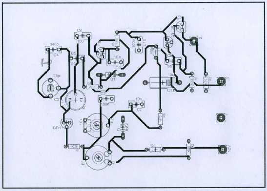
26 VFO board

27 Finished VFO board

28 Amplifier circuit

29 Amplifier circuit board

30 Finished amplifier board

31 DDS20 from CONRAD Electronic
32 Measurements and results Finished boards were tested for their functionalities using oscilloscope. Properties measured include: Tuning characteristics Frequency stability 1. frequency drift over time 2. frequency drifts over temperature 3. supply voltage pulling
33 Tuning Characteristics Voltage source of 12V, 50mA current source and spectrum analyzer were used. Tuning were made with and without amplification Start frequency 4.0MHz Stop frequency 50MHz Center frequency 27MHz Marker frequency 6.83MHz
34 Frequency drift over time at 12V for: LCO DDS20 Time (minutes) f = f 2 f f = f 2 f
35 Frequency drifts over time for both Oscillators at 12V 0,004 Change in frequency (MHz) 0, ,002-0,004-0,006-0,008-0, LC- Oscillator DDS Time (minutes)
36 Frequency drift over temperature for LCO Time (minutes) Temperature ( C) Frequency (MHz) f = f 2 f 1 Start (30 minutes)
37 Frequency drift over temperature for DDS20 Time (minutes) Temperature ( C) Frequency (MHz) f = f 2 f 1 Start
38 Frequency drifts over temperature for both Oscillators per 20 minutes interval 0,1 Change in Frequency (MHz) 0, , ,1 LC- Oscillator DDS -0,15 Temperature ( C)
39 At a temperature of 75 C, the DDS20 went off whereas the LCO was still operational.
40 Supply voltage pulling for LCO Time (minutes) Tuning Voltage (V) Frequency (MHz) f = f 2 f
41 Supply voltage pulling for DDS20 Time (minutes) Tuning Voltage (V) Frequency (MHz) f = f 2 f , , , , , , , ,
42 Frequency variation due to supply voltage pulling for both oscillators per 10 minutes interval 0,04 Change in frequency (MHz) 0,03 0,02 0,01 0-0, LC- Oscillator DDS Tuning Voltage (V)
43 Output spectrum for LCO without amplification
44 Output spectrum for DDS20 witout amplification
45 Output spectrum for LCO with amplification
46 Output spectrum for DDS20 with amplification
47 Conclusions Frequency variations in the LCO are possibly due to its internal variations called aging for the drift over time. Drift over temperature is also due to sensitivity to ambient temperature of the L and C components in the LC-tank. LCO withstood as high as 75 C but DDS went off. Amplified spectral analysis showed that the DDS was more affected by spurious and damping relative to fundamental signal than the LCO. This maybe partly due to instrument used. DDS is more cumbersome than the LCO.
48 From literature, LCO is known to have higher quality factor, Q, than the DDS due to its crystal composition and smaller size. LCO is cheaper to build and when well designed, would give satisfactorily good results Therefore, LCO, from my analysis and based on economic factors, is a good choice and with a little improvement, will match better standards than the DDS. Current state of the art gives the DDS a perfect choice over the LCO.
49 The END!!!!!!! Thank you! Danke!
f o Fig ECE 6440 Frequency Synthesizers P.E. Allen Frequency Magnitude Spectral impurity Frequency Fig010-03
 Lecture 010 Introduction to Synthesizers (5/5/03) Page 010-1 LECTURE 010 INTRODUCTION TO FREQUENCY SYNTHESIZERS (References: [1,5,9,10]) What is a Synthesizer? A frequency synthesizer is the means by which
UNIT 2. Q.1) Describe the functioning of standard signal generator. Ans. Electronic Measurements & Instrumentation
 Describe the functioning of standard signal generator. Ans. Electronic Measurements & Instrumentation") UNIT 2 Q.1) Describe the functioning of standard signal generator Ans. STANDARD SIGNAL GENERATOR A standard signal generator produces known and controllable voltages. It is used as power source for the
UNIT 2 Q.1) Describe the functioning of standard signal generator Ans. STANDARD SIGNAL GENERATOR A standard signal generator produces known and controllable voltages. It is used as power source for the
Definitions. Spectrum Analyzer
 SIGNAL ANALYZERS Spectrum Analyzer Definitions A spectrum analyzer measures the magnitude of an input signal versus frequency within the full frequency range of the instrument. The primary use is to measure
UNIT-3. Electronic Measurements & Instrumentation
 UNIT-3 1. Draw the Block Schematic of AF Wave analyzer and explain its principle and Working? ANS: The wave analyzer consists of a very narrow pass-band filter section which can Be tuned to a particular
Oscillators. An oscillator may be described as a source of alternating voltage. It is different than amplifier.
 Oscillators An oscillator may be described as a source of alternating voltage. It is different than amplifier. An amplifier delivers an output signal whose waveform corresponds to the input signal but
TECHNICAL MANUAL TM0110-2
 TECHNICAL MANUAL TM0110-2 RUBIDIUM FREQUENCY STANDARD MODEL FE-5680A SERIES OPTION 2 OPERATION AND MAINTENANCE INSTRUCTIONS Rubidium Frequency Standard Model FE-5680A with Option 2 Frequency Electronics,
RFID Systems: Radio Architecture
 RFID Systems: Radio Architecture 1 A discussion of radio architecture and RFID. What are the critical pieces? Familiarity with how radio and especially RFID radios are designed will allow you to make correct
Session 3. CMOS RF IC Design Principles
 Session 3 CMOS RF IC Design Principles Session Delivered by: D. Varun 1 Session Topics Standards RF wireless communications Multi standard RF transceivers RF front end architectures Frequency down conversion
The G4EGQ RAE COURSE Lesson 9 Transmitters Lesson 8 looked at a simple transmitter exciter comprising of oscillator, buffer and multiplier stages.
 Lesson 8 looked at a simple transmitter exciter comprising of oscillator, buffer and multiplier stages. The power amplifier The output from the exciter is usually very low and it is necessary to amplify
SC5307A/SC5308A 100 khz to 6 GHz RF Downconverter. Datasheet SignalCore, Inc.
 SC5307A/SC5308A 100 khz to 6 GHz RF Downconverter Datasheet 2017 SignalCore, Inc. support@signalcore.com P RODUCT S PECIFICATIONS Definition of Terms The following terms are used throughout this datasheet
SC5407A/SC5408A 100 khz to 6 GHz RF Upconverter. Datasheet. Rev SignalCore, Inc.
 SC5407A/SC5408A 100 khz to 6 GHz RF Upconverter Datasheet Rev 1.2 2017 SignalCore, Inc. support@signalcore.com P R O D U C T S P E C I F I C A T I O N S Definition of Terms The following terms are used
Lab 4. Crystal Oscillator
 Lab 4. Crystal Oscillator Modeling the Piezo Electric Quartz Crystal Most oscillators employed for RF and microwave applications use a resonator to set the frequency of oscillation. It is desirable to
Twelve voice signals, each band-limited to 3 khz, are frequency -multiplexed using 1 khz guard bands between channels and between the main carrier
 Twelve voice signals, each band-limited to 3 khz, are frequency -multiplexed using 1 khz guard bands between channels and between the main carrier and the first channel. The modulation of the main carrier
Table of Contents Lesson One Lesson Two Lesson Three Lesson Four Lesson Five PREVIEW COPY
 Oscillators Table of Contents Lesson One Lesson Two Lesson Three Introduction to Oscillators...3 Flip-Flops...19 Logic Clocks...37 Lesson Four Filters and Waveforms...53 Lesson Five Troubleshooting Oscillators...69
A FREQUENCY SYNTHESIZER STRUCTURE BASED ON COINCIDENCE MIXER
 3 A FREQUENCY SYNTHESIZER STRUCTURE BASED ON COINCIDENCE MIXER Milan STORK University of West Bohemia UWB, P.O. Box 314, 30614 Plzen, Czech Republic stork@kae.zcu.cz Keywords: Coincidence, Frequency mixer,
Experiment No. 2 Pre-Lab Signal Mixing and Amplitude Modulation
 Experiment No. 2 Pre-Lab Signal Mixing and Amplitude Modulation Read the information presented in this pre-lab and answer the questions given. Submit the answers to your lab instructor before the experimental
PART 20 IF_IN LO_V CC 10 TANK 11 TANK 13 LO_GND I_IN 5 Q_IN 6 Q_IN 7 Q_IN 18 V CC
 19-0455; Rev 1; 9/98 EALUATION KIT AAILABLE 3, Ultra-Low-Power Quadrature General Description The combines a quadrature modulator and quadrature demodulator with a supporting oscillator and divide-by-8
The Design and Construction of a DDS based Waveform Generator
 1 The Design and Construction of a DDS based Waveform Generator Darrell Harmon Abstract A direct digital synthesis (DDS) based signal generator was designed and constructed to cover the frequency range
for use Supervisor: on chip
 Local Oscillator for use in FM Broadcast Radio Receiver ETI 041: Radio Project Supervisor: Göran Jönsson Student: Yelin Wang and Hao Cai Master Program: System on chip Lund University Abstract Oscillator
Experiment 1 LRC Transients
 Physics 263 Experiment 1 LRC Transients 1 Introduction In this experiment we will study the damped oscillations and other transient waveforms produced in a circuit containing an inductor, a capacitor,
Direct Digital Synthesis Primer
 Direct Digital Synthesis Primer Ken Gentile, Systems Engineer ken.gentile@analog.com David Brandon, Applications Engineer David.Brandon@analog.com Ted Harris, Applications Engineer Ted.Harris@analog.com
QUICK START GUIDE FOR DEMONSTRATION CIRCUIT 678A 40MHZ TO 900MHZ DIRECT CONVERSION QUADRATURE DEMODULATOR
 DESCRIPTION QUICK START GUIDE FOR DEMONSTRATION CIRCUIT 678A LT5517 Demonstration circuit 678A is a 40MHz to 900MHz Direct Conversion Quadrature Demodulator featuring the LT5517. The LT 5517 is a direct
SC5306B 1 MHz to 3.9 GHz RF Downconverter Core Module. Datasheet SignalCore, Inc.
 SC5306B 1 MHz to 3.9 GHz RF Downconverter Core Module Datasheet 2015 SignalCore, Inc. support@signalcore.com SC5306B S PECIFICATIONS Definition of Terms The following terms are used throughout this datasheet
EE301 ELECTRONIC CIRCUITS CHAPTER 2 : OSCILLATORS. Lecturer : Engr. Muhammad Muizz Bin Mohd Nawawi
 EE301 ELECTRONIC CIRCUITS CHAPTER 2 : OSCILLATORS Lecturer : Engr. Muhammad Muizz Bin Mohd Nawawi 2.1 INTRODUCTION An electronic circuit which is designed to generate a periodic waveform continuously at
Section 10: Radio Frequency Communication
 Section 10: Radio Frequency Communication Section Contents This section contains the following: Introducing Radio Frequency on page 10-2 RF Amplifier with Thermal Noise Source on page 10-4. Worksheets
i. At the start-up of oscillation there is an excess negative resistance (-R)
") OSCILLATORS Andrew Dearn * Introduction The designers of monolithic or integrated oscillators usually have the available process dictated to them by overall system requirements such as frequency of operation
OSCILLATORS Andrew Dearn * Introduction The designers of monolithic or integrated oscillators usually have the available process dictated to them by overall system requirements such as frequency of operation
INTRODUCTION TO TRANSCEIVER DESIGN ECE3103 ADVANCED TELECOMMUNICATION SYSTEMS
 INTRODUCTION TO TRANSCEIVER DESIGN ECE3103 ADVANCED TELECOMMUNICATION SYSTEMS FUNCTIONS OF A TRANSMITTER The basic functions of a transmitter are: a) up-conversion: move signal to desired RF carrier frequency.
HAMEG Programmable Measuring Instruments Series 8100
 HAMEG Programmable Measuring Instruments Series 8100 HAMEG Programmable Measuring Instruments Series 8100 are ideally suited for test installations in production and automated tests in laboratories. They
HF Receivers, Part 3
 HF Receivers, Part 3 Introduction to frequency synthesis; ancillary receiver functions Adam Farson VA7OJ View an excellent tutorial on receivers Another link to receiver principles NSARC HF Operators HF
RF/IF Terminology and Specs
 RF/IF Terminology and Specs Contributors: Brad Brannon John Greichen Leo McHugh Eamon Nash Eberhard Brunner 1 Terminology LNA - Low-Noise Amplifier. A specialized amplifier to boost the very small received
Experiment No. 3 Pre-Lab Phase Locked Loops and Frequency Modulation
 Experiment No. 3 Pre-Lab Phase Locked Loops and Frequency Modulation The Pre-Labs are informational and although they follow the procedures in the experiment, they are to be completed outside of the laboratory.
CHAPTER 5 NOVEL CARRIER FUNCTION FOR FUNDAMENTAL FORTIFICATION IN VSI
 98 CHAPTER 5 NOVEL CARRIER FUNCTION FOR FUNDAMENTAL FORTIFICATION IN VSI 5.1 INTRODUCTION This chapter deals with the design and development of FPGA based PWM generation with the focus on to improve the
RF Integrated Circuits
 Introduction and Motivation RF Integrated Circuits The recent explosion in the radio frequency (RF) and wireless market has caught the semiconductor industry by surprise. The increasing demand for affordable
Quadrature Upconverter for Optical Comms subcarrier generation
 Quadrature Upconverter for Optical Comms subcarrier generation Andy Talbot G4JNT 2011-07-27 Basic Design Overview This source is designed for upconverting a baseband I/Q source such as from SDR transmitter
Problems from the 3 rd edition
 (2.1-1) Find the energies of the signals: a) sin t, 0 t π b) sin t, 0 t π c) 2 sin t, 0 t π d) sin (t-2π), 2π t 4π Problems from the 3 rd edition Comment on the effect on energy of sign change, time shifting
MASSACHUSETTS INSTITUTE OF TECHNOLOGY HAYSTACK OBSERVATORY WESTFORD, MASSACHUSETTS
 UVLBI MEMO #006 MASSACHUSETTS INSTITUTE OF TECHNOLOGY HAYSTACK OBSERVATORY WESTFORD, MASSACHUSETTS 01886 October 26, 2005 Telephone: 781-981-5407 Fax: 781-981-0590 To: UVLBI Group/SMA From: Shep Doeleman
EVALUATION KIT AVAILABLE 10MHz to 1050MHz Integrated RF Oscillator with Buffered Outputs. Typical Operating Circuit. 10nH 1000pF MAX2620 BIAS SUPPLY
 19-1248; Rev 1; 5/98 EVALUATION KIT AVAILABLE 10MHz to 1050MHz Integrated General Description The combines a low-noise oscillator with two output buffers in a low-cost, plastic surface-mount, ultra-small
CHAPTER 13 TRANSMITTERS AND RECEIVERS
 CHAPTER 13 TRANSMITTERS AND RECEIVERS Frequency Modulation (FM) Receiver Frequency Modulation (FM) Receiver FREQUENCY MODULATION (FM) RECEIVER Superheterodyne Receiver Heterodyning The word heterodyne
Unprecedented wealth of signals for virtually any requirement
 Dual-Channel Arbitrary / Function Generator R&S AM300 Unprecedented wealth of signals for virtually any requirement The new Dual-Channel Arbitrary / Function Generator R&S AM300 ideally complements the
FlexDDS-NG DUAL. Dual-Channel 400 MHz Agile Waveform Generator
 FlexDDS-NG DUAL Dual-Channel 400 MHz Agile Waveform Generator Excellent signal quality Rapid parameter changes Phase-continuous sweeps High speed analog modulation Wieserlabs UG www.wieserlabs.com FlexDDS-NG
Receiver Architecture
 Receiver Architecture Receiver basics Channel selection why not at RF? BPF first or LNA first? Direct digitization of RF signal Receiver architectures Sub-sampling receiver noise problem Heterodyne receiver
Design of a Regenerative Receiver for the Short-Wave Bands A Tutorial and Design Guide for Experimental Work. Part I
 Design of a Regenerative Receiver for the Short-Wave Bands A Tutorial and Design Guide for Experimental Work Part I Ramón Vargas Patrón rvargas@inictel-uni.edu.pe INICTEL-UNI Regenerative Receivers remain
Radio Receiver Architectures and Analysis
 Radio Receiver Architectures and Analysis Robert Wilson December 6, 01 Abstract This article discusses some common receiver architectures and analyzes some of the impairments that apply to each. 1 Contents
Operational Amplifiers: Part II
 1. Introduction Operational Amplifiers: Part II The name "operational amplifier" comes from this amplifier's ability to perform mathematical operations. Three good examples of this are the summing amplifier,
INC. MICROWAVE. A Spectrum Control Business
 DRO Selection Guide DIELECTRIC RESONATOR OSCILLATORS Model Number Frequency Free Running, Mechanically Tuned Mechanical Tuning BW (MHz) +10 MDR2100 2.5-6.0 +10 6.0-21.0 +20 Free Running, Mechanically Tuned,
Acoustics, signals & systems for audiology. Week 4. Signals through Systems
 Acoustics, signals & systems for audiology Week 4 Signals through Systems Crucial ideas Any signal can be constructed as a sum of sine waves In a linear time-invariant (LTI) system, the response to a sinusoid
Glossary of VCO terms
 Glossary of VCO terms VOLTAGE CONTROLLED OSCILLATOR (VCO): This is an oscillator designed so the output frequency can be changed by applying a voltage to its control port or tuning port. FREQUENCY TUNING
Laboratory Assignment 5 Amplitude Modulation
 Laboratory Assignment 5 Amplitude Modulation PURPOSE In this assignment, you will explore the use of digital computers for the analysis, design, synthesis, and simulation of an amplitude modulation (AM)
Tuned Radio Frequency Receiver (TRF) The most elementary receiver design, consisting of RF amplifier stages, detector and audio amplifier stages.
 The most elementary receiver design, consisting of RF amplifier stages, detector and audio amplifier stages.") Figure 3-1 Simple radio receiver block diagram. Tuned Radio Frequency Receiver (TRF) The most elementary receiver design, consisting of RF amplifier stages, detector and audio amplifier stages. Jeffrey
Figure 3-1 Simple radio receiver block diagram. Tuned Radio Frequency Receiver (TRF) The most elementary receiver design, consisting of RF amplifier stages, detector and audio amplifier stages. Jeffrey
OBJECTIVES EQUIPMENT LIST
 1 Reception of Amplitude Modulated Signals AM Demodulation OBJECTIVES The purpose of this experiment is to show how the amplitude-modulated signals are demodulated to obtain the original signal. Also,
8.5 Modulation of Signals
 8.5 Modulation of Signals basic idea and goals measuring atomic absorption without modulation measuring atomic absorption with modulation the tuned amplifier, diode rectifier and low pass the lock-in amplifier
Chapter 6. FM Circuits
 Chapter 6 FM Circuits Topics Covered 6-1: Frequency Modulators 6-2: Frequency Demodulators Objectives You should be able to: Explain the operation of an FM modulators and demodulators. Compare and contrast;
Dr.-Ing. Ulrich L. Rohde
 Dr.-Ing. Ulrich L. Rohde Noise in Oscillators with Active Inductors Presented to the Faculty 3 : Mechanical engineering, Electrical engineering and industrial engineering, Brandenburg University of Technology
Miniproject: AM Radio
 Objective UNIVERSITY OF CALIFORNIA AT BERKELEY College of Engineering Department of Electrical Engineering and Computer Sciences EE05 Lab Experiments Miniproject: AM Radio Until now, the labs have focused
Lecture 7: Components of Phase Locked Loop (PLL)
") Lecture 7: Components of Phase Locked Loop (PLL) CSCE 6933/5933 Instructor: Saraju P. Mohanty, Ph. D. NOTE: The figures, text etc included in slides are borrowed from various books, websites, authors pages,
Lecture 7: Components of Phase Locked Loop (PLL) CSCE 6933/5933 Instructor: Saraju P. Mohanty, Ph. D. NOTE: The figures, text etc included in slides are borrowed from various books, websites, authors pages,
4/30/2012. General Class Element 3 Course Presentation. Practical Circuits. Practical Circuits. Subelement G7. 2 Exam Questions, 2 Groups
 General Class Element 3 Course Presentation ti ELEMENT 3 SUB ELEMENTS General Licensing Class Subelement G7 2 Exam Questions, 2 Groups G1 Commission s Rules G2 Operating Procedures G3 Radio Wave Propagation
Analysis of Phase Noise Profile of a 1.1 GHz Phase-locked Loop
 Analysis of Phase Noise Profile of a 1.1 GHz Phase-locked Loop J. Handique, Member, IAENG and T. Bezboruah, Member, IAENG 1 Abstract We analyzed the phase noise of a 1.1 GHz phaselocked loop system for
433MHz front-end with the SA601 or SA620
 433MHz front-end with the SA60 or SA620 AN9502 Author: Rob Bouwer ABSTRACT Although designed for GHz, the SA60 and SA620 can also be used in the 433MHz ISM band. The SA60 performs amplification of the
A DSP IMPLEMENTED DIGITAL FM MULTIPLEXING SYSTEM
 A DSP IMPLEMENTED DIGITAL FM MULTIPLEXING SYSTEM Item Type text; Proceedings Authors Rosenthal, Glenn K. Publisher International Foundation for Telemetering Journal International Telemetering Conference
BANDPASS delta sigma ( ) modulators are used to digitize
 modulators are used to digitize") 680 IEEE TRANSACTIONS ON CIRCUITS AND SYSTEMS II: EXPRESS BRIEFS, VOL. 52, NO. 10, OCTOBER 2005 A Time-Delay Jitter-Insensitive Continuous-Time Bandpass 16 Modulator Architecture Anurag Pulincherry, Michael
680 IEEE TRANSACTIONS ON CIRCUITS AND SYSTEMS II: EXPRESS BRIEFS, VOL. 52, NO. 10, OCTOBER 2005 A Time-Delay Jitter-Insensitive Continuous-Time Bandpass 16 Modulator Architecture Anurag Pulincherry, Michael
Instructor s Manual to accompany
 Instructor s Manual to accompany MODERN ELECTRONIC COMMUNICATION Ninth Edition Jeffrey S. Beasley Gary M. Miller Upper Saddle River, New Jersey Columbus, Ohio Copyright 2008 by Pearson Education, Inc.,
Tuesday, March 29th, 9:15 11:30
 Oscillators, Phase Locked Loops Tuesday, March 29th, 9:15 11:30 Snorre Aunet (sa@ifi.uio.no) Nanoelectronics group Department of Informatics University of Oslo Last time and today, Tuesday 29th of March:
Laboratory Exercise 6 THE OSCILLOSCOPE
 Introduction Laboratory Exercise 6 THE OSCILLOSCOPE The aim of this exercise is to introduce you to the oscilloscope (often just called a scope), the most versatile and ubiquitous laboratory measuring
DEFINITION: Classification of oscillators Based on the frequency generated Oscillator type Frequency range
 DEFINITION: An oscillator is just an electronic circuit which converts dc energy into AC energy of required frequency. (Or) An oscillator is an electronic circuit which produces an ac output without any
MAHALAKSHMI ENGINEERING COLLEGE TIRUCHIRAPALLI UNIT III TUNED AMPLIFIERS PART A (2 Marks)
") MAHALAKSHMI ENGINEERING COLLEGE TIRUCHIRAPALLI-621213. UNIT III TUNED AMPLIFIERS PART A (2 Marks) 1. What is meant by tuned amplifiers? Tuned amplifiers are amplifiers that are designed to reject a certain
MAHALAKSHMI ENGINEERING COLLEGE TIRUCHIRAPALLI-621213. UNIT III TUNED AMPLIFIERS PART A (2 Marks) 1. What is meant by tuned amplifiers? Tuned amplifiers are amplifiers that are designed to reject a certain
4/29/2012. General Class Element 3 Course Presentation. Signals and Emissions. SignalSignals and Emissionsissions. Subelement G8
 General Class Element 3 Course Presentation ti ELEMENT 3 SUB ELEMENTS General Licensing Class Subelement G8 Signals and Emissions 2 Exam Questions, 2 Groups G1 Commission s Rules G2 Operating Procedures
Low frequency tuned amplifier. and oscillator using simulated. inductor*
 CHAPTER 5 Low frequency tuned amplifier and oscillator using simulated inductor* * Partial contents of this Chapter has been published in. D.Susan, S.Jayalalitha, Low frequency amplifier and oscillator
Chapter 2. The Fundamentals of Electronics: A Review
 Chapter 2 The Fundamentals of Electronics: A Review Topics Covered 2-1: Gain, Attenuation, and Decibels 2-2: Tuned Circuits 2-3: Filters 2-4: Fourier Theory 2-1: Gain, Attenuation, and Decibels Most circuits
Table of Contents...2. About the Tutorial...6. Audience...6. Prerequisites...6. Copyright & Disclaimer EMI INTRODUCTION Voltmeter...
 1 Table of Contents Table of Contents...2 About the Tutorial...6 Audience...6 Prerequisites...6 Copyright & Disclaimer...6 1. EMI INTRODUCTION... 7 Voltmeter...7 Ammeter...8 Ohmmeter...8 Multimeter...9
General Class License Theory II. Dick Grote K6PBF
 General Class License Theory II Dick Grote K6PBF k6pbfdick@gmail.com 1 Introduction In the first theory class we talked about basic electrical principles and components. Now we will build on this to learn
CMPT 368: Lecture 4 Amplitude Modulation (AM) Synthesis
 Synthesis") CMPT 368: Lecture 4 Amplitude Modulation (AM) Synthesis Tamara Smyth, tamaras@cs.sfu.ca School of Computing Science, Simon Fraser University January 8, 008 Beat Notes What happens when we add two frequencies
CMPT 368: Lecture 4 Amplitude Modulation (AM) Synthesis Tamara Smyth, tamaras@cs.sfu.ca School of Computing Science, Simon Fraser University January 8, 008 Beat Notes What happens when we add two frequencies
A 3 TO 30 MHZ HIGH-RESOLUTION SYNTHESIZER CONSISTING OF A DDS, DIVIDE-AND-MIX MODULES, AND A M/N SYNTHESIZER. Richard K. Karlquist
 A 3 TO 30 MHZ HIGH-RESOLUTION SYNTHESIZER CONSISTING OF A DDS, -AND-MIX MODULES, AND A M/N SYNTHESIZER Richard K. Karlquist Hewlett-Packard Laboratories 3500 Deer Creek Rd., MS 26M-3 Palo Alto, CA 94303-1392
Section 1. Fundamentals of DDS Technology
 Section 1. Fundamentals of DDS Technology Overview Direct digital synthesis (DDS) is a technique for using digital data processing blocks as a means to generate a frequency- and phase-tunable output signal
Communication Systems. Department of Electronics and Electrical Engineering
 COMM 704: Communication Lecture 6: Oscillators (Continued) Dr Mohamed Abd El Ghany Dr. Mohamed Abd El Ghany, Mohamed.abdel-ghany@guc.edu.eg Course Outline Introduction Multipliers Filters Oscillators Power
Fast Tuning Synthesizer
 Project Member: Nathan Roth Project Advisors: Dr. Brian Huggins Dr. Prasad Shastry Mr. James Jensen Date: November 18, 2003 Fast Tuning Synthesizer System Level Block Diagram Overview A frequency synthesizer
Modeling And Implementation of All-Digital Phase-Locked Loop Based on Vernier Gated Ring Oscillator Time-to-Digital Converter
 Master s Thesis Modeling And Implementation of All-Digital Phase-Locked Loop Based on Vernier Gated Ring Oscillator Time-to-Digital Converter Ji Wang Department of Electrical and Information Technology,
CHAPTER 3 OSCILOSCOPE AND SIGNAL CONDITIONING
 CHAPTER 3 OSCILOSCOPE AND SIGNAL CONDITIONING OUTLINE Introduction to Signal Generator Oscillator Requirement for Oscillation Positive Feedback Amplifier Oscillator Radio Frequency Oscillator Introduction
Topic Advanced Radio Receivers. Explain that an RF amplifier can be used to improve sensitivity;
 Learning Objectives: At the end of this topic you will be able to; Explain that an RF amplifier can be used to improve sensitivity; Explain that a superheterodyne receiver offers improved selectivity and
Technical Article A DIRECT QUADRATURE MODULATOR IC FOR 0.9 TO 2.5 GHZ WIRELESS SYSTEMS
 Introduction As wireless system designs have moved from carrier frequencies at approximately 9 MHz to wider bandwidth applications like Personal Communication System (PCS) phones at 1.8 GHz and wireless
Figure 1: Closed Loop System
 SIGNAL GENERATORS 3. Introduction Signal sources have a variety of applications including checking stage gain, frequency response, and alignment in receivers and in a wide range of other electronics equipment.
Integrated Circuit Design for High-Speed Frequency Synthesis
 Integrated Circuit Design for High-Speed Frequency Synthesis John Rogers Calvin Plett Foster Dai ARTECH H O US E BOSTON LONDON artechhouse.com Preface XI CHAPTER 1 Introduction 1 1.1 Introduction to Frequency
Lab 4. Crystal Oscillator
 Lab 4. Crystal Oscillator Modeling the Piezo Electric Quartz Crystal Most oscillators employed for RF and microwave applications use a resonator to set the frequency of oscillation. It is desirable to
EC202- ELECTRONIC CIRCUITS II Unit- I -FEEEDBACK AMPLIFIER
 EC202- ELECTRONIC CIRCUITS II Unit- I -FEEEDBACK AMPLIFIER 1. What is feedback? What are the types of feedback? 2. Define positive feedback. What are its merits and demerits? 3. Define negative feedback.
When you have completed this exercise, you will be able to relate the gain and bandwidth of an op amp
 Op Amp Fundamentals When you have completed this exercise, you will be able to relate the gain and bandwidth of an op amp In general, the parameters are interactive. However, in this unit, circuit input
Publication Number ATFxxB Series DDS FUNCTION WAVEFORM GENERATOR. User s Guide
 Publication Number 101201 ATFxxB Series DDS FUNCTION WAVEFORM GENERATOR User s Guide Introduction This user's guide is used for all models of ATFxxB series of DDS function generator. xx in the model number
CHAPTER 5 DESIGN OF SINUSOIDAL PULSE WIDTH MODULATION TECHNIQUES FOR ZETA CONVERTER USING FPGA
 82 CHAPTER 5 DESIGN OF SINUSOIDAL PULSE WIDTH MODULATION TECHNIQUES FOR ZETA CONVERTER USING FPGA 5.1 Introduction Similar to the SEPIC DC/DC converter topology, the ZETA converter topology provides a
FREQUENCY RESPONSE OF R, L AND C ELEMENTS
 FREQUENCY RESPONSE OF R, L AND C ELEMENTS Marking scheme : Methods & diagrams : 3 Graph plotting : - Tables & analysis : 2 Questions & discussion : 3 Performance : 2 Aim: This experiment will investigate
Feedback Loop Canceller Circuit
 Feedback Loop Canceller Circuit Bachelor Thesis Ahmad Bader Ibrahim Obeidat Supervised by Prof. Dr.-Ing. Klaus Solbach 17.11.2014 Outline: 1 Motivation 2 Circuit description 3 Tasks and objectives 4 Active
Long Range Passive RF-ID Tag With UWB Transmitter
 Long Range Passive RF-ID Tag With UWB Transmitter Seunghyun Lee Seunghyun Oh Yonghyun Shim seansl@umich.edu austeban@umich.edu yhshim@umich.edu About RF-ID Tag What is a RF-ID Tag? An object for the identification
Receiver Architectures
 Receiver Architectures Modules: VCO (2), Quadrature Utilities (2), Utilities, Adder, Multiplier, Phase Shifter (2), Tuneable LPF (2), 100-kHz Channel Filters, Audio Oscillator, Noise Generator, Speech,
AN1995 Evaluating the SA605 SO and SSOP demo-board
 RF COMMUNICATIONS PRODUCTS Evaluating the SA605 SO and SSOP demo-board Alvin K. Wong 997 Oct 9 Philips Semiconductors Author: Alvin K. Wong INTRODUCTION With the increasing demand for smaller and lighter
Study of Inductive and Capacitive Reactance and RLC Resonance
 Objective Study of Inductive and Capacitive Reactance and RLC Resonance To understand how the reactance of inductors and capacitors change with frequency, and how the two can cancel each other to leave
Exercise 1: RF Stage, Mixer, and IF Filter
 SSB Reception Analog Communications Exercise 1: RF Stage, Mixer, and IF Filter EXERCISE OBJECTIVE DISCUSSION On the circuit board, you will set up the SSB transmitter to transmit a 1000 khz SSB signal
Filters And Waveform Shaping
 Physics 3330 Experiment #3 Fall 2001 Purpose Filters And Waveform Shaping The aim of this experiment is to study the frequency filtering properties of passive (R, C, and L) circuits for sine waves, and
Angle Modulation, II. Lecture topics. FM bandwidth and Carson s rule. Spectral analysis of FM. Narrowband FM Modulation. Wideband FM Modulation
 Angle Modulation, II Lecture topics FM bandwidth and Carson s rule Spectral analysis of FM Narrowband FM Modulation Wideband FM Modulation Bandwidth of Angle-Modulated Waves Angle modulation is nonlinear
10MHz to 1050MHz Integrated RF Oscillator with Buffered Outputs
 9-24; Rev 2; 2/02 EVALUATION KIT AVAILABLE 0MHz to 050MHz Integrated General Description The combines a low-noise oscillator with two output buffers in a low-cost, plastic surface-mount, ultra-small µmax
Low distortion signal generator based on direct digital synthesis for ADC characterization
 ACTA IMEKO July 2012, Volume 1, Number 1, 59 64 www.imeko.org Low distortion signal generator based on direct digital synthesis for ADC characterization Walter F. Adad, Ricardo J. Iuzzolino Instituto Nacional
SHF Communication Technologies AG. Wilhelm-von-Siemens-Str. 23D Berlin Germany. Phone Fax
 SHF Communication Technologies AG Wilhelm-von-Siemens-Str. 23D 12277 Berlin Germany Phone +49 30 772051-0 Fax ++49 30 7531078 E-Mail: sales@shf.de Web: http://www.shf.de Application Note Jitter Injection
The New England Radio Discussion Society electronics course (Phase 4, cont d) Introduction to receivers
 Introduction to receivers") The New England Radio Discussion Society electronics course (Phase 4, cont d) Introduction to receivers AI2Q April 2017 REVIEW: a VFO, phase-locked loop (PLL), or direct digital synthesizer (DDS), can
The New England Radio Discussion Society electronics course (Phase 4, cont d) Introduction to receivers AI2Q April 2017 REVIEW: a VFO, phase-locked loop (PLL), or direct digital synthesizer (DDS), can
Feedback and Oscillator Circuits
 Chapter 14 Chapter 14 Feedback and Oscillator Circuits Feedback Concepts The effects of negative feedback on an amplifier: Disadvantage Lower gain Advantages Higher input impedance More stable gain Improved