or Op Amps for short
|
|
|
- Flora Johnson
- 6 years ago
- Views:
Transcription
1 or Op Amps for short
2 Objective of Lecture Describe how an ideal operational amplifier (op amp) behaves. Chapter 14.1 Electrical Engineering: Principles and Applications Chapter Fundamentals of Electric Circuits Define voltage gain, current gain, transresistance gain, and transconductance gain. Chapter Electrical Engineering: Principles and Applications Explain the operation of an ideal op amp in a voltage comparator and inverting amplifier circuit. Show the effect of using a real op amp.
3 Op Amps Applications Audio amplifiers Speakers and microphone circuits in cell phones, computers, mpg players, boom boxes, etc. Instrumentation amplifiers Biomedical systems including heart monitors and oxygen sensors. Power amplifiers Analog computers Combination of integrators, differentiators, summing amplifiers, and multipliers
4 Symbols for Ideal and Real Op Amps OpAmp ua741 LM111 LM324
5 Terminals on an Op Amp Non-inverting Input terminal Positive power supply (Positive rail) Output terminal Inverting input terminal Negative power supply (Negative rail)
6 Op Amp Equivalent Circuit v 2 v d = v 2 v 1 A is the open-loop voltage gain v 1 Voltage controlled voltage source
7 Typical Op Amp Parameters Parameter Variable Typical Ranges Open-Loop Voltage Gain Ideal Values A 10 5 to 10 8 Input Resistance Output Resistance Ri 10 5 to Ω Ω Ro 10 to 100 Ω 0 Ω Supply Voltage Vcc/V + -Vcc/V - 5 to 30 V -30V to 0V N/A N/A
8 How to Find These Values Component Datasheets Many manufacturers have made these freely available on the internet Example: LM 324 Operational Amplifier
9
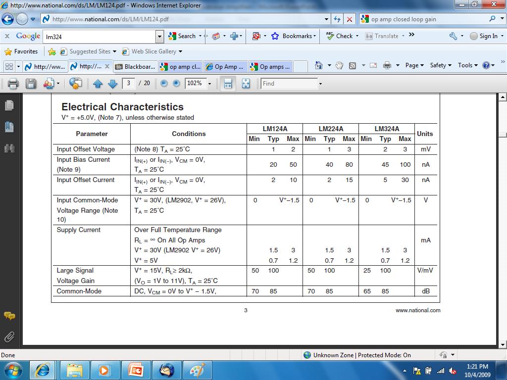
10 db Decibels Since P = V 2 /R 10 log (P/P ref ) or 20 log (V/V ref ) In this case: 20 log (V o /V in ) = 20 log (A) = 100 A = 10 5 = 100,000
11
12 Large Signal Voltage Gain = A Typical A = 100 V/mV = 100V/0.001V = 100,000 Minimum A = 25 V/mV = 25 V/0.001V = 25,000
13 Caution A is Frequency Dependent
14 Open Circuit Output Voltage v o = A v d Ideal Op Amp v o = (v d )
15 Open Circuit Output Voltage Real Op Amp Voltage Range Output Voltage Positive Saturation A v d > V + v o ~ V + Linear Region V - < A v d < V + v o = A v d Negative A v d < V - v o ~ V - Saturation The voltage produced by the dependent voltage source inside the op amp is limited by the voltage applied to the positive and negative rails.
16 Voltage Transfer Characteristic Range where we operate the op amp as an amplifier. v d
17 Ideal Op Amp Because Ri is equal to Ω, the voltage across Ri is 0V. v 2 i 2 = 0 v 1 = v 2 v d = 0 V v 1 i 1 = 0
18 Almost Ideal Op Amp Ri = Ω Therefore, i 1 = i 2 = 0A Ro = 0 Ω Usually, v d = 0V so v 1 = v 2 The op amp forces the voltage at the inverting input terminal to be equal to the voltage at the noninverting input terminal if there is some component connecting the output terminal to the inverting input terminal. Rarely is the op amp limited to V - < v o < V +. The output voltage is allowed to be as positive or as negative as needed to force v d = 0V.
19 Example #1: Voltage Comparator i s = 0 i 1 = 0 i 2 = 0 Note that the inverting input and non-inverting input terminals have rotated in this schematic.
20 Example #1 (con t) The internal circuitry in the op amp tries to force the voltage at the inverting input to be equal to the noninverting input. As we will see shortly, a number of op amp circuits have a resistor between the output terminal and the inverting input terminals to allow the output voltage to influence the value of the voltage at the inverting input terminal.
21 Example #1: Voltage Comparator i s = 0 i 1 = 0 i 2 = 0 When Vs is equal to 0V, Vo = 0V. When Vs is smaller than 0V, Vo = V +. When Vs is larger than 0V, Vo = V -.
22 Electronic Response Given how an op amp functions, what do you expect Vo to be if v2 = 5V when: 1. Vs = 0V? 2. Vs = 5V? 3. Vs = 6V?
23 Example #2: Closed Loop Gain i f i s i 1 = 0 v 1 i 2 = 0 v 2
24 Example #2 (con t) i f i s i 1 i o i 2 For an almost ideal op amp, Ri = Ω and Ro = 0 Ω. The output voltage will never reach V + or V -.
25 Example #2 (con t) Virtual ground i f i s i 1 i i 2 The op amp outputs a voltage Vo such that V1 = V2.
26 Example #2 (con t) i s i 1 i f i i 2
27 Example #2: Closed Loop Gain This circuit is known as an inverting amplifier / / / 0 R R A R R V v i i i i R v R i V V v f V f s o f s f f o s S = = = = = = = C A B
28 Types of Gain i f i s i 1 i o i i 2
29 Types of Closed Loop Gain Gain Variable Name Equation Units Voltage Gain A V v o /v s None or V/V Current Gain A I i o /i s None or A/A Transresistance Gain A R v o /i s V/A or Ω Transconductance Gain A G i o /v s A/V or Ω 1
30 Example #3: Closed Loop Gain with Real Op Amp i f i s i 1 v 1 i i 2 v 2
31 Example #3 (con t) i s = i 1 + i f i = i f - i 1 = i 2 v d = v 2 v 1 = Ri (- i 1 ) = Ri (i 2 ) V o = Av d - Ro(- i) V s = R1(i s ) v d V s = R1(i s ) + Rf(i f ) + V o V o /V s = (-R f /R1){Aβ/[1 +Aβ]}, where β = R1/(R1+R f )
32 Summary The output of an ideal op amp is a voltage from a dependent voltage source that attempts to force the voltage at the inverting input terminal to equal the voltage at the non-inverting input terminal. Almost ideal op amp: Output voltage limited to the range between V + and V -. Ideal op amp is assumed to have Ri = Ω and Ro = 0 Ω. Almost ideal op amp: v d = 0 V and the current flowing into the output terminal of the op amp is as much as required to force v 1 = v 2 when V + < v o < V -. Operation of an op amp was used in the analysis of voltage comparator and inverting amplifier circuits. Effect of Ri < Ω and Ro > 0 Ω was shown.
An electronic unit that behaves like a voltagecontrolled
 1 An electronic unit that behaves like a voltagecontrolled voltage source. An active circuit element that amplifies, sums, subtracts, multiply, divide, differentiate or integrates a signal 2 A typical
Introduction to Operational Amplifiers
 P. R. Nelson ECE 322 Fall 2012 p. 1/50 Introduction to Operational Amplifiers Phyllis R. Nelson prnelson@csupomona.edu Professor, Department of Electrical and Computer Engineering California State Polytechnic
Operational Amplifiers
 Fundamentals of op-amp Operation modes Golden rules of op-amp Op-amp circuits Inverting & non-inverting amplifier Unity follower, integrator & differentiator Introduction An operational amplifier, or op-amp,
Chapter 3: Operational Amplifiers
 Chapter 3: Operational Amplifiers 1 OPERATIONAL AMPLIFIERS Having learned the basic laws and theorems for circuit analysis, we are now ready to study an active circuit element of paramount importance:
CENG4480 Lecture 02: Operational Amplifier 1
 CENG4480 Lecture 02: Operational Amplifier 1 Bei Yu 2016 Fall byu@cse.cuhk.edu.hk 1 / 33 Overview Introduction Op-Amp Preliminaries Op-Amp List 2 / 33 Overview Introduction Op-Amp Preliminaries Op-Amp
Designing Information Devices and Systems I Discussion 10A
 Last Updated: 2019-04-09 07:42 1 EECS 16A Spring 2019 Designing Information Devices and Systems I Discussion 10A For Reference: Circuits Cookbook, Abridged Voltage Divider Voltage Summer Unity Gain Buffer
What s an Analog Signal?
 What s an Analog Signal? Derived from the word analogous (analogous to the original signal) Our most powerful electronic systems are digital systems, e.g. computers, however, analog signals are required
Operational Amplifiers (Op Amps)
") Operational Amplifiers (Op Amps) Introduction * An operational amplifier is modeled as a voltage controlled voltage source. * An operational amplifier has a very high input impedance and a very high gain.
Operational Amplifiers (Op Amps) Introduction * An operational amplifier is modeled as a voltage controlled voltage source. * An operational amplifier has a very high input impedance and a very high gain.
Introduction to Analog Interfacing. ECE/CS 5780/6780: Embedded System Design. Various Op Amps. Ideal Op Amps
 Introduction to Analog Interfacing ECE/CS 5780/6780: Embedded System Design Scott R. Little Lecture 19: Operational Amplifiers Most embedded systems include components that measure and/or control real-world
Emitter Coupled Differential Amplifier
 Emitter Coupled Differential Amplifier Returning to the transistor, a very common and useful circuit is the differential amplifier. It's basic circuit is: Vcc Q1 Q2 Re Vee To see how this circuit works,
CHAPTER 11. Feedback. Microelectronic Circuits, Seventh Edition. Copyright 2015 by Oxford University Press
 CHAPTER 11 Feedback Figure 11.1 General structure of the feedback amplifier. This is a signal-flow diagram, and the quantities x represent either voltage or current signals. Figure 11.2 Determining the
Introduction to Op Amps
 Introduction to Op Amps ENGI 242 ELEC 222 Basic Op-Amp The op-amp is a differential amplifier with a very high open loop gain 25k AVOL 500k (much higher for FET inputs) high input impedance 500kΩ ZIN 10MΩ
using dc inputs. You will verify circuit operation with a multimeter.
 Op Amp Fundamentals using dc inputs. You will verify circuit operation with a multimeter. FACET by Lab-Volt 77 Op Amp Fundamentals O circuit common. a. inverts the input voltage polarity. b. does not invert
The Operational Amplifier as a differential voltage-controlled voltage source
 The Operational Amplifier as a differential voltage-controlled voltage source Operational amplifiers (op amps) are high performance differential amplifiers. They have inverting and noninverting inputs
EET 438a Automatic Control Systems Technology Laboratory 1 Analog Sensor Signal Conditioning
 EET 438a Automatic Control Systems Technology Laboratory 1 Analog Sensor Signal Conditioning Objectives: Use analog OP AMP circuits to scale the output of a sensor to signal levels commonly found in practical
Infrared Communications Lab
 Infrared Communications Lab This lab assignment assumes that the student knows about: Ohm s Law oltage, Current and Resistance Operational Amplifiers (See Appendix I) The first part of the lab is to develop
EE LINEAR INTEGRATED CIRCUITS & APPLICATIONS
 UNITII CHARACTERISTICS OF OPAMP 1. What is an opamp? List its functions. The opamp is a multi terminal device, which internally is quite complex. It is a direct coupled high gain amplifier consisting of
Università degli Studi di Roma Tor Vergata Dipartimento di Ingegneria Elettronica. Analogue Electronics. Paolo Colantonio A.A.
 Università degli Studi di Roma Tor Vergata Dipartimento di Ingegneria Elettronica Analogue Electronics Paolo Colantonio A.A. 2056 Operational amplifiers (op amps) Operational amplifiers (op amps) are among
Lesson number one. Operational Amplifier Basics
 What About Lesson number one Operational Amplifier Basics As well as resistors and capacitors, Operational Amplifiers, or Op-amps as they are more commonly called, are one of the basic building blocks
University of Pittsburgh
 University of Pittsburgh Experiment #7 Lab Report Analog-Digital Applications Submission Date: 08/01/2018 Instructors: Dr. Ahmed Dallal Shangqian Gao Submitted By: Nick Haver & Alex Williams Station #2
ES250: Electrical Science. HW6: The Operational Amplifier
 ES250: Electrical Science HW6: The Operational Amplifier Introduction This chapter introduces the operational amplifier or op amp We will learn how to analyze and design circuits that contain op amps,
Common Reference Example
 Operational Amplifiers Overview Common reference circuit diagrams Real models of operational amplifiers Ideal models operational amplifiers Inverting amplifiers Noninverting amplifiers Summing amplifiers
What is an Op-Amp? The Surface
 What is an Op-Amp? The Surface An Operational Amplifier (Op-Amp) is an integrated circuit that uses external voltage to amplify the input through a very high gain. We recognize an Op-Amp as a massproduced
Chapter 10: Operational Amplifiers
 Chapter 10: Operational Amplifiers Differential Amplifier Differential amplifier has two identical transistors with two inputs and two outputs. 2 Differential Amplifier Differential amplifier has two identical
Operational amplifiers
 Operational amplifiers Bởi: Sy Hien Dinh INTRODUCTION Having learned the basic laws and theorems for circuit analysis, we are now ready to study an active circuit element of paramount importance: the operational
Operational Amplifiers
 Operational Amplifiers From: http://ume.gatech.edu/mechatroni cs_course/opamp_f11.ppt What is an Op-Amp? The Surface An Operational Amplifier (Op-Amp) is an integrated circuit that uses external voltage
Linear IC s and applications
 Questions and Solutions PART-A Unit-1 INTRODUCTION TO OP-AMPS 1. Explain data acquisition system Jan13 DATA ACQUISITION SYSYTEM BLOCK DIAGRAM: Input stage Intermediate stage Level shifting stage Output
UNIT - 1 OPERATIONAL AMPLIFIER FUNDAMENTALS
 UNIT - 1 OPERATIONAL AMPLIFIER FUNDAMENTALS 1.1 Basic operational amplifier circuit- hte basic circuit of an operational amplifier is as shown in above fig. has a differential amplifier input stage and
Assist Lecturer: Marwa Maki. Active Filters
 Active Filters In past lecture we noticed that the main disadvantage of Passive Filters is that the amplitude of the output signals is less than that of the input signals, i.e., the gain is never greater
EEE225: Analogue and Digital Electronics
 EEE225: Analogue and Digital Electronics Lecture II James E. Green Department of Electronic Engineering University of Sheffield j.e.green@sheffield.ac.uk This Lecture 1 One Transistor Circuits Continued...
Operational Amplifiers. Boylestad Chapter 10
 Operational Amplifiers Boylestad Chapter 10 DC-Offset Parameters Even when the input voltage is zero, an op-amp can have an output offset. The following can cause this offset: Input offset voltage Input
Lecture Notes Unit-III
 Lecture Notes Unit-III FAQs Q1: An operational amplifier has a differential gain of 103 and CMRR of 100, input voltages are 120µV and 80µV, determine output voltage. 2 MARKS
University of Portland EE 271 Electrical Circuits Laboratory. Experiment: Op Amps
 University of Portland EE 271 Electrical Circuits Laboratory Experiment: Op Amps I. Objective The objective of this experiment is to learn how to use an op amp circuit to prevent loading and to amplify
Unit WorkBook 1 Level 4 ENG U22 Electronic Circuits and Devices 2018 UniCourse Ltd. All Rights Reserved. Sample
 Pearson BTEC Level 4 Higher Nationals in Engineering (RQF) Unit 22: Electronic Circuits and Devices Unit Workbook 1 in a series of 4 for this unit Learning Outcome 1 Operational Amplifiers Page 1 of 23
C H A P T E R 02. Operational Amplifiers
 C H A P T E R 02 Operational Amplifiers The Op-amp Figure 2.1 Circuit symbol for the op amp. Figure 2.2 The op amp shown connected to dc power supplies. The Ideal Op-amp 1. Infinite input impedance 2.
Rowan University Freshman Clinic I Lab Project 2 The Operational Amplifier (Op Amp)
") Rowan University Freshman Clinic I Lab Project 2 The Operational Amplifier (Op Amp) Objectives Become familiar with an Operational Amplifier (Op Amp) electronic device and it operation Learn several basic
Rowan University Freshman Clinic I Lab Project 2 The Operational Amplifier (Op Amp) Objectives Become familiar with an Operational Amplifier (Op Amp) electronic device and it operation Learn several basic
Section 4: Operational Amplifiers
 Section 4: Operational Amplifiers Op Amps Integrated circuits Simpler to understand than transistors Get back to linear systems, but now with gain Come in various forms Comparators Full Op Amps Differential
Example #6 1. An amplifier with a nominal gain
 1. An amplifier with a nominal gain A=1000 V/V exhibits a gain change of 10% as the operating temperature changes from 25 o C to 75 o C. If it is required to constrain the change to 0.1% by applying negative
+ power. V out. - power +12 V -12 V +12 V -12 V
 Question 1 Questions An operational amplifier is a particular type of differential amplifier. Most op-amps receive two input voltage signals and output one voltage signal: power 1 2 - power Here is a single
Experiments #7. Operational Amplifier part 1
 Experiments #7 Operational Amplifier part 1 1) Objectives: The objective of this lab is to study operational amplifier (op amp) and its applications. We will be simulating and building some basic op-amp
ELECTRONICS. EE 42/100 Lecture 8: Op-Amps. Rev B 3/3/2010 (9:13 PM) Prof. Ali M. Niknejad
 Prof. Ali M. Niknejad") A. M. Niknejad University of California, Berkeley EE 100 / 42 Lecture 8 p. 1/21 EE 42/100 Lecture 8: Op-Amps ELECTRONICS Rev B 3/3/2010 (9:13 PM) Prof. Ali M. Niknejad University of California, Berkeley
A. M. Niknejad University of California, Berkeley EE 100 / 42 Lecture 8 p. 1/21 EE 42/100 Lecture 8: Op-Amps ELECTRONICS Rev B 3/3/2010 (9:13 PM) Prof. Ali M. Niknejad University of California, Berkeley
Introduction to Op Amps By Russell Anderson, Burr-Brown Corp
 Introduction to Op Amps By ussell Anderson, BurrBrown Corp Introduction Analog design can be intimidating. If your engineering talents have been focused in digital, software or even scientific fields,
ELECTRONICS. EE 42/100 Lecture 8: Op-Amps. Rev A 2/10/2010 (6:47 PM) Prof. Ali M. Niknejad
 Prof. Ali M. Niknejad") A. M. Niknejad University of California, Berkeley EE 100 / 42 Lecture 8 p. 1/21 EE 42/100 Lecture 8: Op-Amps ELECTRONICS Rev A 2/10/2010 (6:47 PM) Prof. Ali M. Niknejad University of California, Berkeley
A. M. Niknejad University of California, Berkeley EE 100 / 42 Lecture 8 p. 1/21 EE 42/100 Lecture 8: Op-Amps ELECTRONICS Rev A 2/10/2010 (6:47 PM) Prof. Ali M. Niknejad University of California, Berkeley
Dual Low Power Operational Amplifier, Single or Dual Supply OP221
 a FEATURES Excellent TCV OS Match, 2 V/ C Max Low Input Offset Voltage, 15 V Max Low Supply Current, 55 A Max Single Supply Operation, 5 V to 3 V Low Input Offset Voltage Drift,.75 V/ C High Open-Loop
2.3 The Non-Inverting Configuration
 2/18/2011 section 2_3 The non inverting configuration 1/1 2.3 The NonInverting Configuration Reading Assignment: pp. Another standard opamp circuit configuration is the noninverting configuration. HO:
Basic Information of Operational Amplifiers
 EC1254 Linear Integrated Circuits Unit I: Part - II Basic Information of Operational Amplifiers Mr. V. VAITHIANATHAN, M.Tech (PhD) Assistant Professor, ECE Department Objectives of this presentation To
Operational Amplifiers
 CHAPTER 5 Operational Amplifiers Operational amplifiers (or Op Amp) is an active circuit element that can perform mathematical operations between signals (e.g., amplify, sum, subtract, multiply, divide,
L02 Operational Amplifiers Applications 1
 L02 Operational Amplifiers Applications 1 Chapter 9 Ideal Operational Amplifiers and Op-Amp Circuits Donald A. Neamen (2009). Microelectronics: Circuit Analysis and Design, 4th Edition, Mc-Graw-Hill Prepared
Chapter 2. Operational Amplifiers
 Chapter 2. Operational Amplifiers Tong In Oh 1 Objective Terminal characteristics of the ideal op amp How to analyze op amp circuits How to use op amps to design amplifiers How to design more sophisticated
Precision, Low Power, Micropower Dual Operational Amplifier OP290
 Precision, Low Power, Micropower Dual Operational Amplifier OP9 FEATURES Single-/dual-supply operation:. V to 3 V, ±.8 V to ±8 V True single-supply operation; input and output voltage Input/output ranges
EECE251 Circuit Analysis I Set 5: Operational Amplifiers
 EECE251 Circuit Analysis I Set 5: Operational Amplifiers Shahriar Mirabbasi Department of Electrical and Computer Engineering University of British Columbia shahriar@ece.ubc.ca 1 Amplifiers There are various
1) Consider the circuit shown in figure below. Compute the output waveform for an input of 5kHz
 Consider the circuit shown in figure below. Compute the output waveform for an input of 5kHz") ) Consider the circuit shown in figure below. Compute the output waveform for an input of 5kHz Solution: a) Input is of constant amplitude of 2 V from 0 to 0. ms and 2 V from 0. ms to 0.2 ms. The output
) Consider the circuit shown in figure below. Compute the output waveform for an input of 5kHz Solution: a) Input is of constant amplitude of 2 V from 0 to 0. ms and 2 V from 0. ms to 0.2 ms. The output
Lecture 4. Integrated Electronics
 Lecture 4 Integrated Electronics P, N is the doping of silicon to carry P (+) or N (-) charge) DIODES -> Recitifier I P N If V > V ON of diode, V V ON I = R Forward bias, conducting I Von ~ 0.6 V Example:
LAB 5 OPERATIONAL AMPLIFIERS
 LAB 5 OPERATIONAL AMPLIFIERS PRE-LAB CALCULATIONS: Use circuit analysis techniques learned in class to analyze the circuit in Figure 5.2. Solve for Vo assuming that the effective resistance of the LED
ECET DAQ & Control Systems
 1 Electrical Engineering Technology ECET 17700 DAQ & Control Systems Lecture # 11 Inverting Amplifier & Summer Professors Robert Herrick & J. Michael Jacob Purdue University ECET 17700 DAQ & Systems Control
Homework Assignment 03
 Homework Assignment 03 Question 1 (Short Takes), 2 points each unless otherwise noted. 1. Two 0.68 μf capacitors are connected in series across a 10 khz sine wave signal source. The total capacitive reactance
Precision, Low Power, Micropower Dual Operational Amplifier OP290
 a FEATURES Single-/Dual-Supply Operation, 1. V to 3 V,. V to 1 V True Single-Supply Operation; Input and Output Voltage Ranges Include Ground Low Supply Current (Per Amplifier), A Max High Output Drive,
General Purpose Operational Amplifiers
 General Purpose Operational Amplifiers OUTLINE Lecture 0, 0/7/05 Corrected 0/9/05 Op-Amp from -Port Blocks Op-Amp Model and its Idealization Negative Feedback for Stability Components around Op-Amp define
Special-Purpose Operational Amplifier Circuits
 Special-Purpose Operational Amplifier Circuits Instrumentation Amplifier An instrumentation amplifier (IA) is a differential voltagegain device that amplifies the difference between the voltages existing
Operational Amplifier BME 360 Lecture Notes Ying Sun
 Operational Amplifier BME 360 Lecture Notes Ying Sun Characteristics of Op-Amp An operational amplifier (op-amp) is an analog integrated circuit that consists of several stages of transistor amplification
Each question is worth 4 points. ST07 One-hour Quiz #2 1 3/20/2007
 Name: Date: DEPARTMENT OF ELECTRICAL ENGINEERING AND COMPUTER SCIENCE MASSACHUSETTS INSTITUTE OF TECHNOLOGY CAMBRIDGE, MASSACHUSETTS 02139 Spring Term 2007 Quiz 2 6.101 Introductory Analog Electronics
MAS.836 HOW TO BIAS AN OP-AMP
 MAS.836 HOW TO BIAS AN OP-AMP Op-Amp Circuits: Bias, in an electronic circuit, describes the steady state operating characteristics with no signal being applied. In an op-amp circuit, the operating characteristic
To configure op-amp in inverting and non-inverting amplifier mode and measure their gain.
 AIM: SUBJECT: ANALOG ELECTRONICS (2392) EXPERIMENT NO. 5 DATE : TITLE: TO CONFIGURE OP-AMP IN INVERTING AND NON- INVERTING AMPLIFIER MODE AND MEASURE THEIR GAIN. DOC. CODE : DIET/EE/3 rd SEM REV. NO. :./JUNE-25
ENGR 201 Homework, Fall 2018
 Chapter 1 Voltage, Current, Circuit Laws (Selected contents from Chapter 1-3 in the text book) 1. What are the following instruments? Draw lines to match them to their cables: Fig. 1-1 2. Complete the
LINEAR IC APPLICATIONS
 1 B.Tech III Year I Semester (R09) Regular & Supplementary Examinations December/January 2013/14 1 (a) Why is R e in an emitter-coupled differential amplifier replaced by a constant current source? (b)
Operational Amplifier (Op-Amp)
") Operational Amplifier (Op-Amp) 1 Contents Op-Amp Characteristics Op-Amp Circuits - Noninverting Amplifier - Inverting Amplifier - Comparator - Differential - Summing - Integrator - Differentiator 2 Introduction
Operational Amplifier (Op-Amp) 1 Contents Op-Amp Characteristics Op-Amp Circuits - Noninverting Amplifier - Inverting Amplifier - Comparator - Differential - Summing - Integrator - Differentiator 2 Introduction
ECEN 5008: Analog IC Design. Final Exam
 ECEN 5008 Initials: 1/10 ECEN 5008: Analog IC Design Final Exam Spring 2004 Instructions: 1. Exam Policy: Time-limited, 150-minute exam. When the time is called, all work must stop. Put your initials on
Analog Electronics. Lecture Pearson Education. Upper Saddle River, NJ, All rights reserved.
 Analog Electronics V Lecture 5 V Operational Amplifers Op-amp is an electronic device that amplify the difference of voltage at its two inputs. V V 8 1 DIP 8 1 DIP 20 SMT 1 8 1 SMT Operational Amplifers
P a g e 1. Introduction
 P a g e 1 Introduction 1. Signals in digital form are more convenient than analog form for processing and control operation. 2. Real world signals originated from temperature, pressure, flow rate, force
Applied Electronics II
 Applied Electronics II Chapter 3: Operational Amplifier Part 1- Op Amp Basics School of Electrical and Computer Engineering Addis Ababa Institute of Technology Addis Ababa University Daniel D./Getachew
UNIVERSITY OF NORTH CAROLINA AT CHARLOTTE Department of Electrical and Computer Engineering
 UNIVERSITY OF NORTH CAROLINA AT CHARLOTTE Department of Electrical and Computer Engineering EXPERIMENT 5 GAIN-BANDWIDTH PRODUCT AND SLEW RATE OBJECTIVES In this experiment the student will explore two
Analog Electronics. Lecture. Op-amp Circuits and Active Filters. Muhammad Amir Yousaf
 Analog Electronics Lecture Op-amp Circuits and Active Filters Muhammad Amir Yousaf Instrumentation Amplifiers An instrumentation amplifier (IA) amplifies the voltage difference between its terminals. It
Homework Assignment 07
 Homework Assignment 07 Question 1 (Short Takes). 2 points each unless otherwise noted. 1. A single-pole op-amp has an open-loop low-frequency gain of A = 10 5 and an open loop, 3-dB frequency of 4 Hz.
Operational amplifiers
 Chapter 8 Operational amplifiers An operational amplifier is a device with two inputs and one output. It takes the difference between the voltages at the two inputs, multiplies by some very large gain,
Operational Amplifiers
 1. Introduction Operational Amplifiers The student will be introduced to the application and analysis of operational amplifiers in this laboratory experiment. The student will apply circuit analysis techniques
User s Manual ISL71218MEVAL1Z. User s Manual: Evaluation Board. High Reliability Space
 User s Manual ISL71218MEVAL1Z User s Manual: Evaluation Board High Reliability Space Rev. Aug 217 USER S MANUAL ISL71218MEVAL1Z Evaluation Board UG139 Rev.. 1. Overview The ISL71218MEVAL1Z evaluation platform
UNIT I. Operational Amplifiers
 UNIT I Operational Amplifiers Operational Amplifier: The operational amplifier is a direct-coupled high gain amplifier. It is a versatile multi-terminal device that can be used to amplify dc as well as
Sensor Interfacing and Operational Amplifiers Lab 3
 Name Lab Day Lab Time Sensor Interfacing and Operational Amplifiers Lab 3 Introduction: In this lab you will design and build a circuit that will convert the temperature indicated by a thermistor s resistance
v 0 = A (v + - v - ) (1)
 (1)") UNIVERSITI TEKNOLOGI MALAYSIA KURSUS KEJURUTERAAN ELEKTRIK ELECTRONIC ENGINEERING LABORATORY 2 EXPERIMENT 2 : OPERATIONAL AMPLIFIER PRELIMINARY REPORT Name : Section : Group : Lecturer : Marks : 20 Attach
UNIVERSITI TEKNOLOGI MALAYSIA KURSUS KEJURUTERAAN ELEKTRIK ELECTRONIC ENGINEERING LABORATORY 2 EXPERIMENT 2 : OPERATIONAL AMPLIFIER PRELIMINARY REPORT Name : Section : Group : Lecturer : Marks : 20 Attach
Homework Assignment 13
 Question 1 Short Takes 2 points each. Homework Assignment 13 1. Classify the type of feedback uses in the circuit below (i.e., shunt-shunt, series-shunt, ) 2. True or false: an engineer uses series-shunt
Signal Conditioning Devices
 Lecture 4. Signal Conditioning Devices Signal Conditioning Operations In previous lectures we have studied various sensors and transducers used in a mechatronics system. Transducers sense physical phenomenon
MAHALAKSHMI ENGINEERING COLLEGE TIRUCHIRAPALLI
 MAHALAKSHMI ENGINEERING COLLEGE TIRUCHIRAPALLI-621213. QUESTION BANK DEPARTMENT: EEE SUBJECT CODE: EE2203 SEMESTER : III SUBJECT NAME: ELECTRONIC DEVICES &CIRCUITS UNIT 4-AMPLIFIERS AND OSCILLATORS PART
Designing Information Devices and Systems I Fall 2018 Homework 10
 Last Updated: 2018-10-27 04:00 1 EECS 16A Designing Information Devices and Systems I Fall 2018 Homework 10 You should plan to complete this homework by Thursday, November 1st. Everything in this homework
UNIT- IV ELECTRONICS
 UNIT- IV ELECTRONICS INTRODUCTION An operational amplifier or OP-AMP is a DC-coupled voltage amplifier with a very high voltage gain. Op-amp is basically a multistage amplifier in which a number of amplifier
Instrumentation Amplifiers Filters Integrators Differentiators Frequency-Gain Relation Non-Linear Op-Amp Applications DC Imperfections
 Lecture Op-Amp Building Blocks and Applications Instrumentation Amplifiers Filters Integrators Differentiators Frequency-Gain elation Non-Linear Op-Amp Applications DC Imperfections ELG439 Check List for
Chapter 9: Operational Amplifiers
 Chapter 9: Operational Amplifiers The Operational Amplifier (or op-amp) is the ideal, simple amplifier. It is an integrated circuit (IC). An IC contains many discrete components (resistors, capacitors,
2. The. op-amp in and 10K. (a) 0 Ω. (c) 0.2% (d) (a) 0.02K. (b) 4. The. 5 V, then. 0V (virtual. (a) (c) Fall V. (d) V.
 0 Ω. (c) 0.2% (d) (a) 0.02K. (b) 4. The. 5 V, then. 0V (virtual. (a) (c) Fall V. (d) V.") Homework Assignment 04 Question 1 (2 points each unless noted otherwise) 1. A 9-V dc power supply generates 10 W in a resistor. What peak-to-peak amplitude should an ac source have to generate the same
Homework Assignment 04 Question 1 (2 points each unless noted otherwise) 1. A 9-V dc power supply generates 10 W in a resistor. What peak-to-peak amplitude should an ac source have to generate the same
Chapter 2. Operational Amplifiers
 Chapter 2. Operational Amplifiers Tong In Oh 1 2.3 The Noninverting Configuration v I is applied directly to the positive input terminal of the op amp One terminal of is connected to ground Closed-loop
Unit WorkBook 4 Level 4 ENG U19 Electrical and Electronic Principles LO4 Digital & Analogue Electronics 2018 Unicourse Ltd. All Rights Reserved.
 Pearson BTEC Levels 4 Higher Nationals in Engineering (RQF) Unit 19: Electrical and Electronic Principles Unit Workbook 4 in a series of 4 for this unit Learning Outcome 4 Digital & Analogue Electronics
EE301 Electronics I , Fall
 EE301 Electronics I 2018-2019, Fall 1. Introduction to Microelectronics (1 Week/3 Hrs.) Introduction, Historical Background, Basic Consepts 2. Rewiev of Semiconductors (1 Week/3 Hrs.) Semiconductor materials
Lecture 11. Operational Amplifier (opamp)
") Lecture 11 Operational Amplifier (opamp) Peter Cheung Department of Electrical & Electronic Engineering Imperial College London URL: www.ee.ic.ac.uk/pcheung/teaching/de1_ee/ E-mail: p.cheung@imperial.ac.uk
Lecture 11 Operational Amplifier (opamp) Peter Cheung Department of Electrical & Electronic Engineering Imperial College London URL: www.ee.ic.ac.uk/pcheung/teaching/de1_ee/ E-mail: p.cheung@imperial.ac.uk
Başkent University Department of Electrical and Electronics Engineering EEM 311 Electronics II Experiment 8 OPERATIONAL AMPLIFIERS
 Başkent University Department of Electrical and Electronics Engineering EEM 311 Electronics II Experiment 8 Objectives: OPERATIONAL AMPLIFIERS 1.To demonstrate an inverting operational amplifier circuit.
While the Riso circuit is both simple to implement and design it has a big disadvantage in precision circuits. The voltage drop from Riso is
 Hello, and welcome to part six of the TI Precision Labs on op amp stability. This lecture will describe the Riso with dual feedback stability compensation method. From 5: The previous videos discussed
Common mode rejection ratio
 Common mode rejection ratio Definition: Common mode rejection ratio represents the ratio of the differential voltage gaina d tothecommonmodevoltagegain,a cm : Common mode rejection ratio Definition: Common
University of Pittsburgh
 University of Pittsburgh Experiment #1 Lab Report Frequency Response of Operational Amplifiers Submission Date: 05/29/2018 Instructors: Dr. Ahmed Dallal Shangqian Gao Submitted By: Nick Haver & Alex Williams
EMT212 Analog Electronic II. Chapter 4. Oscillator
 EMT Analog Electronic II Chapter 4 Oscillator Objectives Describe the basic concept of an oscillator Discuss the basic principles of operation of an oscillator Analyze the operation of RC, LC and crystal
Intro To Engineering II for ECE: Lab 7 The Op Amp Erin Webster and Dr. Jay Weitzen, c 2014 All rights reserved.
 Lab 7: The Op Amp Laboratory Objectives: 1) To introduce the operational amplifier or Op Amp 2) To learn the non-inverting mode 3) To learn the inverting mode 4) To learn the differential mode Before You
11. Chapter: Amplitude stabilization of the harmonic oscillator
 Punčochář, Mohylová: TELO, Chapter 10 1 11. Chapter: Amplitude stabilization of the harmonic oscillator Time of study: 3 hours Goals: the student should be able to define basic principles of oscillator
Section3 Chapter 2: Operational Amplifiers
 2012 Section3 Chapter 2: Operational Amplifiers Reference : Microelectronic circuits Sedra six edition 1/10/2012 Contents: 1- THE Ideal operational amplifier 2- Inverting configuration a. Closed loop gain
Differential Amplifier : input. resistance. Differential amplifiers are widely used in engineering instrumentation
 Differential Amplifier : input resistance Differential amplifiers are widely used in engineering instrumentation Differential Amplifier : input resistance v 2 v 1 ir 1 ir 1 2iR 1 R in v 2 i v 1 2R 1 Differential