ELECTRICAL INSTALLATION OPERATION MANUAL
|
|
|
- Antonia Price
- 6 years ago
- Views:
Transcription

1 AC TECH SMV Series ELECTRICAL INSTALLATION & OPERATION MANUAL All installation wiring must conform to the Canadian Electrical Code and local codes. While we believe that using Envira- North's controls and following our instructions will result in an installation that meets those requirements, we cannot guarantee it. Code compliance is ultimately the installer's and/or user's responsibility. Subject to changes without notification 1
2 TABLE OF CONTENTS Cover page 1 Table of contents 2 Wiring positions 3 Wiring positions diagrams 4 Wire type 5 Wire lengths 6 Motor wiring 7 Dimension & Connections of VFD 8 Operation of fan controller 12 To remote control a single VFDs 13 To remote control multiple VFDs 15 Operation of the Low Voltage Control TFD-1 to multiples SMV VFDs 18 Operation of TFD-1 with VFD 19 Wiring of TFD-1 to LVC 20 Operation of TFD-1 with LVC 21 2
3 WIRING POSITIONS (see following page for diagrams) Position #1 - Variable Frequency Drive (VFD) mounted at eye-level, you need to bring the input power cable to the VFD, then an inverter-rated cable from the VFD to the motor. Position #2 - VFD mounted at eye-level and controlled by a Low Voltage Controller (LVC) (the temperature controller (TFD-1) is optional), you need to bring the input power cable to the VFD, then an inverter-rated cable from the VFD to the motor. A control cable can be daisy-chained between the LVC and the VFDs. Position #3 - VFD mounted at eye-level and controlled by a TFD-1, you need to bring the input power cable to the VFD, then an inverter-rated cable from the VFD to the motor. A control cable can be daisy-chained between the TFD-1 and the VFDs. Position #4 - VFD mounted on the fan frame and controlled by a LVC, you need to bring the input power cable to the VFD, the inverter-rated cable from the VFD to the motor is pre-wired. A control cable is needed between the LVC and the VFD. Position #5 - VFD mounted on the fan frame and controlled by a LVC, you need to bring the input power cable to the VFD, the inverter-rated cable from the VFD to the motor is pre-wired. A control cable can be daisy-chained between the LVC and the VFDs. Position #6 - VFD mounted on the fan frame and controlled by a LVC and a Temperature Controller, you need to bring the input power cable to the VFD, the inverter-rated cable from the VFD to the motor is pre-wired. A control cable can be daisy-chained between the LVC and the VFDs. A control cable is needed between the LVC and TFD-1. 3

4 WIRING POSITIONS OPTIONS CEILING POSITION #4 POSITION #5 POSITION #6 4
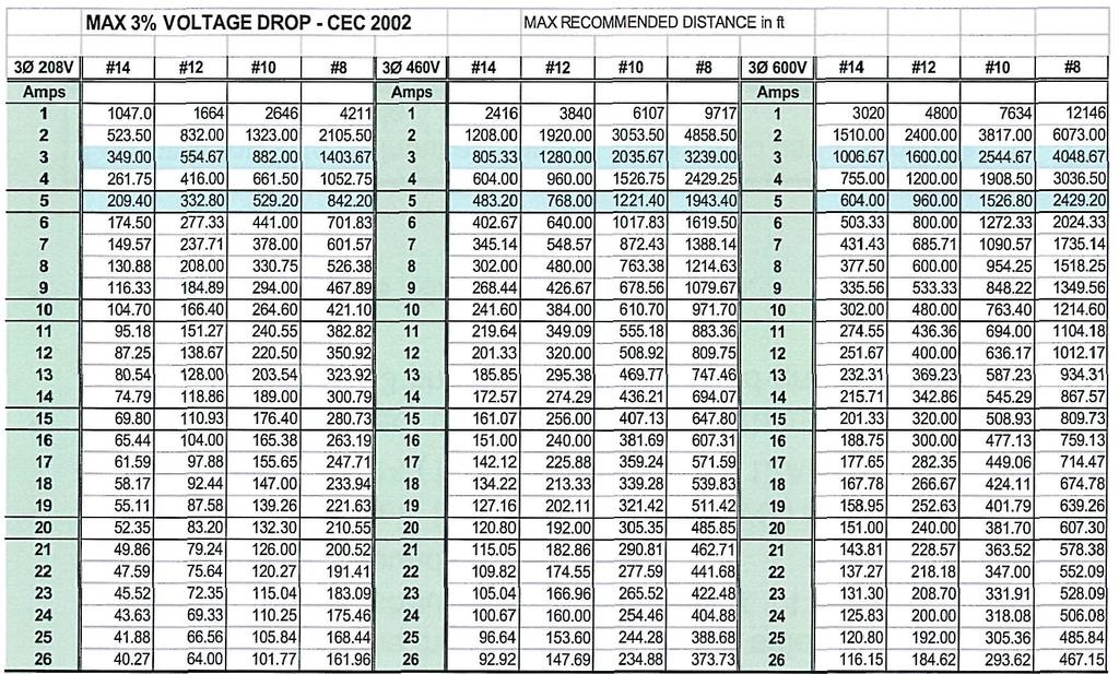
5 WIRE TYPE The wires/cable between the Variable Frequency Drive (VFD) and the motor must be the inverter-duty type, if a shielded cable is used. The shielded cable should be a minimum 4x14 AWG (3 phase wires + insulated ground). Recommended cables: Belden (14AWG) or (12AWG) or Alpha Wire V16014 (14AWG) or V16012 (12AWG) If EMT conduit is used, then the proper wire rating must be used. 14 AWG minimum x 4 (3 phase wires + insulated ground). Proper bonding is required. For control wires use 18AWG shielded cable. Separate conduits for input and output power; also use a separate conduit for control cable 5
6 6


7 T1 T2 T3 460VAC From VFD From VFD T3 T2 T1 T3 T2 T1 From VFD T1 T2 T3 230VAC 460VAC 230VAC 7
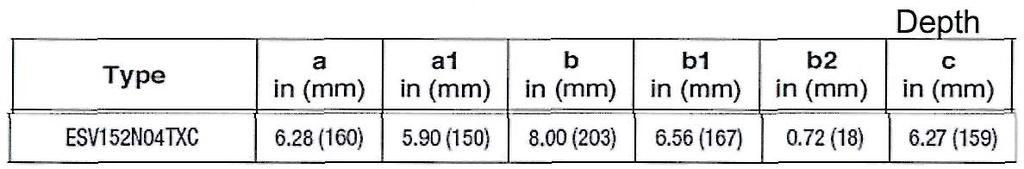
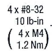
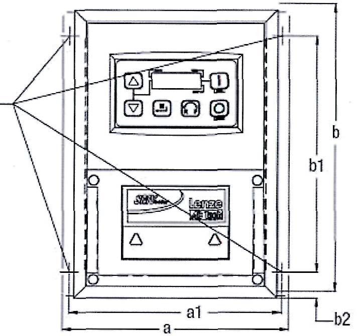
8 DIMENSION CONNECTIONS 8

9 To Fan To VFD IMPORTANT: Input and output cables must be in different EMT conduits. The output power cable to the fan must NOT be in a conduit with other cables. Disconnect switch (not provided with VFD) 9


10 To Fans ESV152N04TXC RIGHT WAY Power in To Fans WRONG WAY Power in 10
 ground wire to motor frame")
11 Connect shield through bonding and connect insulated (Green) ground wire to motor frame 11

12 OPERATION INSTRUCTIONS for the AC TECH SMV SGG To start: Press the To stop: Press the To change speed: Press the To change the rotation: Press the Then press the within 4 seconds to confirm the change 12

13 SGG To remote AC TECH SMV Series 13
14 ALsw P VDC P120-1 LOW AL P RUN FWD P RUN REV To remote AC TECH SMV Series SGG 14
15 7 wires to 1 st VFD (18AWG Shielded) SGG 1 st SMV VFD Terminal 6 not connected between 1 st and 2 nd VFD 2nd SMV VFD Terminal 6 not connected between 2 nd and 3 rd VFD 3rd SMV VFD To remote AC TECH SMV Series 15


16 To Fans AC power in cables can be shared in the same conduit Control cables can be shared together but not with power SGG cables Output cables can not be shared together or with other power/control cables 16
17 OPERATION INSTRUCTIONS of the Low Voltage Controller TO START THE FAN: Before turning on disconnect switch, verify that the direction switch is in the "OFF" position and the emergency stop in pushed in. Apply power by turning on the disconnect switch. To put the fan in operation, select the desired direction and then release the emergency switch by turning it clockwise. TO ADJUST THE SPEED: Turn the potentiometer (SPEED) to the desired speed. TO TURN OFF FAN OPERATION: Depress the emergency stop switch TO RESTART FAN OPERATION AFTER DEPRESS EMERGENCY STOP: Release the emergency switch by turning it clockwise SGG AC TECH SMV Series 17
18 TO NEXT VFD (DAISY-CHAIN) Temp Probe CONNECTIONS BETWEEN TFD-1 AND MULTIPLES SMV VFDs (No LV Controller) 18
19 OPERATION OF TFD-1 To reverse or forward the direction of the fan while in motion, change the direction using the "forward/reverse" switch on the SMV VFD. Leave this switch in either position for the fan to operate with the TFD-1 temperature controller. Setup of TFD-1 Temperature Controller. - Rotate Selector dial to position (1) Set point - Rotate the Adjustor dial to desired set point temperature. Example 20 C - Rotate Selector dial to position (2) Modulation band - Rotate the Adjustor dial to desired modulation band. Example 10 C - Rotate Selector dial to position (3) Minimum ventilation off - Rotate the Adjustor dial to desired minimum. Example 5 C Temperature (in Celsius) - In the example above, from start-up the fan will start to turn only if the barn temperature reaches 20 C. The speed that will be indicated on the fan controller should be approximately 15Hz. As the temperature rises in the barn the fan will increase speed until the temperature reaches the end of the modulation band. At 30 C (set point + modulation band) the fan will be at its maximum (60Hz on the fan controller). - As the temperature decreases the speed will decrease until you reach the set point (20 C). At that point the speed will be at its minimum (around 15Hz on the fan controller). As the temperature decreases below the set point, the fan will continue to operate at its minimum rate until you reach 15 C (set point minus the minimum ventilation off). - Below the point of 15 C, the fan will stop and will remain in the off condition until the temperature rises to the set point (20 C) and then the cycle repeats itself. NOTE: The minimum speed has been programmed to 15 Hz. DO NOT lower it pass this limit otherwise your warranty will be void. Lowering the speed below 15 Hz will cause the motor to overheat because the motor will not draw enough air to cool down at these low speeds SGG 19

 2008082901SGG")
20 Low Voltage Controller TFD-1 Temperature Controller SW1 shown in Manual position 240VAC 1PH 4 wires to TFD-1 (18AWG Shielded) SGG LVC with TFD-1 20
21 OPERATION NOTES ON LOW VOLTAGE CONTROLLER AND TFD-1 TEMPERATURE CONTROLLER DO NOT TURN OFF THE FAN WHILE IN MOTION USING THE DISCONNECT SWITCH. To stop the fan from normal operation, use the forward/off/reverse switch to OFF on the Low Voltage Controller. Always use the RED EMERGENCY button (on the right of the Low Voltage Controller) to turn off or stop the fan In case of an emergency. To reverse or forward the direction of the fan while in motion, change the direction using the "forward/reverse" switch. Leave this switch in either position for the fan to operate with the TFD-1 temperature controller. Setup of TFD-1 Temperature Controller. - Rotate Selector dial to position (1) Set point - Rotate the Adjustor dial to desired set point temperature. - Rotate Selector dial to position (2) Modulation band - Rotate the Adjustor dial to desired modulation band. - Rotate Selector dial to position (3) Minimum ventilation off - Rotate the Adjustor dial to desired minimum. Temperature (in Celcius) - In the example above, from start-up the fan will start to turn only if the interior building temperature reaches 20 C. The speed that will be indicated on the fan controller should be approximately 15Hz. As the temperature rises in the building the fan will increase speed until the temperature reaches the end of the modulation band. At 30 C (set point + modulation band) the fan will be at its maximum (60Hz on the fan controller). - As the temperature decreases the speed will decrease until you reach the set point (20 C). At that point the speed will be at its minimum (around 16 on the fan controller). As the temperature decreases below the set point, the fan will continue to operate at its minimum rate until you reach 15 C (set point minus the minimum ventilation off). - Below this point of 15 C the fan will stop and will stay in the off condition until the temperature rises to the set point (20 C) and then the cycle repeats itself. NOTES: The minimum speed has been programmed to 15 Hz. DO NOT lower it pass this limit otherwise your warranty will be void. Lowering the speed below 15Hz will cause the motor to overheat because the motor will not draw enough air to cool down at these low speeds SGG 21
ELECTRICAL INSTALLATION
 ELECTRICAL INSTALLATION Subject to change without notice. All installation wiring must conform to your country Electrical Code and local codes. While we believe that using NORDOCK s controls and following
3% VOLTAGE DROP. Installation Instructions for 400 Watt 24 Volt DC RGB DMX LED Power Supply SAVE THESE INSTRUCTIONS!
 Installation Instructions for 400 Watt 24 Volt DC RGB DMX LED Power Supply Doc # 904-PSB-400W-24VDC_06 1718 W. Fullerton Chicago, IL 60614 Ph: 773.770.1195 Fax: 773.935.5613 www.pureedgelighting.com info@pureedgelighting.com
BULLETIN # B
 Page 1 of 9 BULLETIN # B-18-2002 From: Parts and Service Division Date: February 14, 2002 To: All Authorized Service Agencies SUBJECT: Convection Oven Controller Troubleshooting MODELS AFFECTED: All Garland
Exercise 3-3. Manual Reversing Starters EXERCISE OBJECTIVE DISCUSSION. Build manual reversing starters and understand how they work.
 Exercise 3-3 Manual Reversing Starters EXERCISE OBJECTIVE Build manual reversing starters and understand how they work. DISCUSSION Reversing motor rotation direction is a common operation in industrial
Operating Instructions
 4XH35QB151210 Small General Frequency Converter Operating Instructions 220V 0.75KW 5.5KW 400V 0.75KW 15KW Please read the instruction carefully and understand the contents so that it can be installed and
Variable Speed Brushed DC Motor Drive
 The driving force of motor control & electronics cooling. Equinox: Variable Speed Brushed DC Motor Drive Navigator Equinox The Equinox variable speed brushed DC motor drive with Navigator Programmer is
MST-5. Varifan USER S MANUAL MST-5 5 STAGE THERMOSTAT. computer compatible ADJUST. 9 reduc. per day 8 7 F rel. rel. rel. rel.
 MST-5 USER S MANUAL 5 STAGE THERMOSTAT computer compatible ALARM 1 2 3 4 5 ALARM F2 12 11 1 on off TIMER 2 PERIOD STAGE 2 10 3 rel Varifan LIMIT HEAT STAGES 9 reduc. per day 8 7 COOL STAGES 6 rel 5 4 COOL/HEAT
LPB OMNI Broadcast Transmitter Installation Procedure Checklist
 Installation Procedure LPB OMNI Broadcast Transmitter Installation Procedure Checklist LPB Communications, Inc. 960 Brook Road, Unit 5 Conshohocken, PA 19428 610-825-4100 phone 610-825-4047 fax www.lpbinc.com!
The GS1 Digital Keypad LED Display Function Keys Displaying the Status of the GS1 AC Drive Programming the GS1 AC Drive...
 CHAPTER KEYPAD OPERATION 3 AND QUICKSTART Contents of this Chapter... The GS1 Digital Keypad................................3 2 LED Display..............................................3 2 Function Keys............................................3
FREQUENCY INVERTER VFR-013 EXTERNAL BUTTONS PILOTAGE. Inoréa Automation & Industry 9 rue du Lugan BEGLES
 FREQUENCY INVERTER VFR-013 EXTERNAL BUTTONS PILOTAGE Inoréa Automation & Industry 9 rue du Lugan 33130 BEGLES www.inorea.com TABLE OF CONTENTS 1. DESCRIPTION... 3 2. DESCRIPTION : TWO ELECTRIC WIRES TYPE
Connection and Operation
 Connection and Operation LED Display Control Module Motor Regeneration Unit Terminals Power Connection Terminals Protective Earth Terminal Internal Potentiometer Acceleration Time Potentiometer Deceleration
Ambient Conditions Storage Conditions Installation Minimum Clearances and Air Flow...2 3
 CHAPTER INSTALLATION 2 AND WIRING Contents of this Chapter... Ambient Conditions..............................2 2 Storage Conditions...............................2 2 Installation.....................................2
CHAPTER KEYPAD OPERATION AND QUICKSTART. In This Chapter... The GS2 Digital Keypad GS2 Quickstart...3 6
 CHAPTER KEYPAD OPERATION 3 AND QUICKSTART In This Chapter... The GS2 Digital Keypad.....................3 2 LED Display.........................................3 2 LED Indicators.......................................3
INSTALLATION AND OPERATION MANUAL IODA INPUT/OUTPUT MULTI-FUNCTION BOARD (Part No. 9668)
") INSTALLATION AND OPERATION MANUAL IODA INPUT/OUTPUT MULTI-FUNCTION BOARD (Part No. 9668) Use with Models KBDA-24D, 27D, 29, 45, 48 See Safety Warning, on page 4. RoHS The information contained in this
INSTALLATION AND OPERATION MANUAL IODA INPUT/OUTPUT MULTI-FUNCTION BOARD (Part No. 9668) Use with Models KBDA-24D, 27D, 29, 45, 48 See Safety Warning, on page 4. RoHS The information contained in this
FREQUENCY INVERTER VFR-091/092 EXTERNAL BUTTONS PILOTAGE
 FREQUENCY INVERTER VFR-091/092 EXTERNAL BUTTONS PILOTAGE Inoréa Automation & Industry 9 rue du Lugan 33130 BEGLES contact@inorea.com www.inorea.com Table of contents 1. DESCRIPTION... 3 2. DESCRIPTION:
S11 Adjustable Speed Drive Engineering Specification
 PART 1 - GENERAL 1.0 Scope This specification shall cover Toshiba S11 AC Variable Frequency Drives, 6 pulse for 3- phase 200-240VAC, 380-500VAC and single phase 200V to 240VAC. 1.1 References A. National
12V Victor 888 User Manual
 The Victor speed controllers are specifically engineered for robotic applications. The high current capacity, low voltage drop, and peak surge capacity make the Victor ideal for drive systems while its
Invertek Optidrive E3 Frequency Inverter (IP20, 3ph output) Easy Start Guide
 Easy Start Guide") Invertek Optidrive E3 Frequency Inverter (IP20, 3ph output) Easy Start Guide The Invertek Optidrive E3 Frequency Inverter range is available to order from inverterdrive.com This guide is intended to complement
Invertek Optidrive E3 Frequency Inverter (IP20, 3ph output) Easy Start Guide The Invertek Optidrive E3 Frequency Inverter range is available to order from inverterdrive.com This guide is intended to complement
BC145 SIGNAL ISOLATOR BOARD
 BC145 SIGNAL ISOLATOR BOARD 4/17 Installation & Operating Manual MN1373 Any trademarks used in this manual are the property of their respective owners. Important: Be sure to check www.baldor.com to download
VFD - D700 Series Specifications. The latest low-cost variable speed control solution for centrifugal pumps.
 VFD - D700 Series Specifications The latest low-cost variable speed control solution for centrifugal pumps. Built-in PID Control to maintain pressure, flow, measured value, and much more 125% overload
Owner s Manual S10 SERIES ELECTRONIC STEP CONTROLLER WITH VERNIER CONTROL
 Owner s Manual S10 SERIES ELECTRONIC STEP CONTROLLER WITH VERNIER CONTROL This manual covers installation, setup, operation and troubleshooting. Read carefully before attempting to install, operate or
CHAPTER 3 WIRING DANGER
 CHAPTER WIRING DANGER Hazardous Voltage Before accessing the AC drive: Disconnect all power to the AC drive. Wait five minutes for DC bus capacitors discharge. Any electrical or mechanical modification
F O R T H E L O V E O F M U S I C LP100 OWNER'S MANUAL AND INSTALLATION GUIDE INTRODUCTION
 F O R T H E L O V E O F M U S I C LP100 OWNER'S MANUAL AND INSTALLATION GUIDE INTRODUCTION You have purchased an amplifier that leads the way with sound quality, reliability, and features. These high performance
1-2 VOLTS PER HERTZ CHARACTERISTICS EXERCISE OBJECTIVE
 1-2 VOLTS PER HERTZ CHARACTERISTICS EXERCISE OBJECTIVE Set the rotation direction of the motor. Understand the V/f (volts per hertz) characteristics. Learn how to use an analog voltage to assign the frequency
2-1 DC DRIVE OVERVIEW EXERCISE OBJECTIVE. Familiarize yourself with the DC Drive. Set the DC Drive parameters to control the DC Motor.
 2-1 DC DRIVE OVERVIEW EXERCISE OBJECTIVE Familiarize yourself with the DC Drive. Set the DC Drive parameters to control the DC Motor. DISCUSSION The DC Drive of your training system is shown in Figure
FREQUENCY INVERTER VFR-013 QUICK START GUIDE
 FREQUENCY INVERTER VFR-013 QUICK START GUIDE Inoréa Automation & Industry 9 rue du Lugan 33130 BEGLES www.inorea.com Table of contents 1. PEOPLE SAFETY... 3 2. MATERIAL SAFETY... 3 3. NAME PLATE... 4 a.
Service Instructions. The Conductor Controls. Conductor DC15-A, Enclosed Unit CH15-A, Open Chasis Unit
 Service Instructions The Conductor Controls Conductor DC15-A, Enclosed Unit CH15-A, Open Chasis Unit Table of Contents General Section Page Safety Instructions.. 4 Introduction 5 Inspection and Long-Term
VF-nC1 Adjustable Speed Drive Engineering Specification
 PART 1 - GENERAL 1.0 Scope This specification shall cover Toshiba VF-nC1 AC Variable Frequency Drives, 6 pulse for 100V single-phase 0.1 to 0.75kW, 200V single-phase 0.2 to 2.2kW and 200V threephase 0.1
FR-ABR-(H)0.4K to 22K
0.4K to 22K") TRANSISTORIZED INVERTER INSTRUCTION MANUAL HIGH-DUTY BRAKE RESISTOR FR-ABR-(H)0.4K to 22K H Thank you for choosing the Mitsubishi transistorized inverter option unit. This instruction manual gives handling
TRANSISTORIZED INVERTER INSTRUCTION MANUAL HIGH-DUTY BRAKE RESISTOR FR-ABR-(H)0.4K to 22K H Thank you for choosing the Mitsubishi transistorized inverter option unit. This instruction manual gives handling
SMVector - Frequency Inverter Operating Instructions
 SMVector - Frequency Inverter Operating Instructions Contents 1 Safety Information...3 2 Technical Data...6 2.1 Standards and Application Conditions...6 2.2 SMV Type Number Designation...7 2.3 Ratings...8
Foreword Thank you for purchasing the general-purpose VF series inverter produced by Panasonic Electric Works Automation Controls (Shanghai) Co., Ltd.
 Co., Ltd.") Inverter VF Instruction Manual [Support model] Three phase 4V (.75kW3.7kW) Read this manual carefully before attempting to operate the inverter and store it for further reference. 8A3 645 7 2 Foreword
Inverter VF Instruction Manual [Support model] Three phase 4V (.75kW3.7kW) Read this manual carefully before attempting to operate the inverter and store it for further reference. 8A3 645 7 2 Foreword
Starbox. Installation guide
 Starbox Installation guide Introduction Welcome The Starbox is a wiring centre that allows ican networks to be wired in a star topology (as an alternative to the standard daisy-chain topology). The Starbox
C-Bus 8 Channel Low Voltage Relay
 SLC5108RELVP Instruction Bulletin Retain for future use. 63249-420-325A1 Instruction Bulletin 07/2009 HAZARD CATEGORIES AND SPECIAL SYMBOLS Read these instructions carefully and look at the equipment to
Technical guide. EC300 motor V8
 l 15/11/2016 1 st release Page 1 sur 7 Electrical installation 230V version : Motor Class I Power supply Voltage (recommended) 200 220..230 277 Vac Voltage (maximum) 174 293 Vac Frequency 48 50 65 Hz Power
MODEL KBWD-15 Pulse Width Modulated (PWM)
") MODEL KBWD-15 Pulse Width Modulated (PWM) DC MOTOR SPEED CONTROL WHISPER DRIVE INSTALLATION AND OPERATING INSTRUCTIONS See Safety Warning on Page 1 and Application Note Warning on Page 2 The information
MODEL KBWD-15 Pulse Width Modulated (PWM) DC MOTOR SPEED CONTROL WHISPER DRIVE INSTALLATION AND OPERATING INSTRUCTIONS See Safety Warning on Page 1 and Application Note Warning on Page 2 The information
Parts Bulletin V"OLV"OPENTA. P QL Thruster Remote Control Models: QL Accessories. AB Volvo Penta SE Goteborg, Sweden
 V"OLV"OPENTA. AB Volvo Penta SE-405 08 Goteborg, Sweden Parts Bulletin Group Number Version P-97-4 12 01 Distribution: Parts Date: 10-2007 Binder: Parts Replaces: QL Thruster Remote Control Models: QL
EVERGREEN EM INSTALLATION GUIDE
 EVERGREEN INSTALLATION GUIDE A Regal Brand Genteq s Evergreen is designed to replace O X13 ECM motors quickly and easily with no programming required. Evergreen provides the same comfort, lower utility
Model PRESET 8 Installation and Operations Manual
 Model PRESET 8 Installation and Operations Manual Doug Fleenor Design, Inc. 396 Corbett Canyon Road Arroyo Grande, CA 93420 (805) 481-9599 Voice and FAX Manual revision March 2, 2015 Page 1 of 7 5 4 3
Excel 10 W7761A Remote Input/Output Device
 Excel 0 W776A Remote Input/Output Device INSTALLATION INSTRUCTIONS PRODUCT DESCRIPTION The W776A Remote Input/Output (RIO) Device is a Free Topology Transceiver (FTT) LonMark compliant device in the Excel
Applicable Standards Cettification Body Standards File No. CE Marking UL 508 UL E91291
 HP-5051-4 Speed Controller MSC-1 OPERATING MANUAL Thank you for purchasing an Oriental Motor product. This Manual describes product handling procedures and safety precautions. Please read it thoroughly
616 PC5 Instruction Manual
 66 PC5 Instruction Manual Power Drive Services Ltd. Unit, Victoria St. Ind. Est. Leigh, WN7 5SE UK Tel +44 (0)942 260206 Fax +44 (0)942 260525 www.inverter.co.uk GPD 505 SIMPLIFIED START-UP PROCEDURE This
Microprocessor Control Board Set Up Procedures (OR PLC)
") Microprocessor Control Board Set Up Procedures (OR-00 PLC) SWITCHES/PUSHBUTTONS Push Buttons at display SW Enter button SW Back button SW Down SW UP Back light on/off switch Rotary switches on main board
Microprocessor Control Board Set Up Procedures (OR-00 PLC) SWITCHES/PUSHBUTTONS Push Buttons at display SW Enter button SW Back button SW Down SW UP Back light on/off switch Rotary switches on main board
Why does the Output's TesysT not switch on?
 Why does the Output's TesysT not switch on? I- Type of publication Typical application Best know Method (BKM) Troubleshooting guide Level 2 use Internal use Customer II- Product - Product range : - Product
SECTION 16483D ADJUSTABLE FREQUENCY DRIVE - MICRODRIVE (MVX <10-HP)
") ADJUSTABLE FREQUENCY DRIVE - MICRODRIVE (MVX
ADJUSTABLE FREQUENCY DRIVE - MICRODRIVE (MVX
Troubleshooting 12. This section explains the items to check when problems occur, and troubleshooting by the use of error displays or operation state.
 Troubleshooting 12 This section explains the items to check when problems occur, and troubleshooting by the use of error displays or operation state. 12-1 Actions for Problems..........................................
HB-25 Motor Controller (#29144)
") Web Site: www.parallax.com Forums: forums.parallax.com Sales: sales@parallax.com Technical: support@parallax.com Office: (916) 624-8333 Fax: (916) 624-8003 Sales: (888) 512-1024 Tech Support: (888) 997-8267
Web Site: www.parallax.com Forums: forums.parallax.com Sales: sales@parallax.com Technical: support@parallax.com Office: (916) 624-8333 Fax: (916) 624-8003 Sales: (888) 512-1024 Tech Support: (888) 997-8267
F O R T H E L O V E O F M U S I C SERIES 218 DPS200 OWNER'S MANUAL AND INSTALLATION GUIDE INTRODUCTION
 F O R T H E L O V E O F M U S I C SERIES 218 DPS200 OWNER'S MANUAL AND INSTALLATION GUIDE INTRODUCTION You have purchased an amplifier that leads the way with sound quality, reliability, and features.
TAC ATV38, IP55. Variable Speed Drives for Asynchronous Motors. 3-phase. 380/460 V, Hz
 TAC ATV8, IP55 Variable Speed Drives for Asynchronous Motors. -phase. 80/460 V, 50-60 Hz E-60-24 24 May 2004 ATV 8 IP55 drives are specifically designed for pump and fan applications powered by a three-phase
VARISPEED V7 IP65 Compact Sensorless Vector Inverter USER S MANUAL
 V7_IP65.qxd 15.02.2006 13:17 Uhr Seite 1 Manual No. I161E-EN-01 VARISPEED V7 IP65 Compact Sensorless Vector Inverter USER S MANUAL OMRON YASKAWA MOTION CONTROL B.V. Wegalaan 65 2132 JD Hoofddorp The Netherlands
PEAKTRONICS AMC-103 ADDITIONAL FEATURES. AC Motor Controller, 2A AMC-103 AMC-103A AMC-103B
 PEAKTRONICS The Peaktronics AC Motor Controller is a compact module that is intended for controlling small AC actuator motors of up to 2A. The is very well suited for applications where space constraints
IRIS \ IRIS-I QUICK SET-UP GUIDE STEP 1 INSTALL
 IRIS \ IRIS-I QUICK SET-UP GUIDE STEP 1 INSTALL Confirm contents of package: 1 sensor, 1 cable, 1 wide lens (default), 1 narrow lens, mounting template, User s Guide. Install the sensor at the desired
5570M Series Intercom Installation and Operation Guide
 5570M Series Intercom Installation and Operation Guide Isolated balanced/unbalanced lines Audio signals for the 5570M are transmitted over a wire pair using balanced line technology. An isolation transformer,
BFS / BFSM SERIES Installation & Maintenance Manual
 Introduction: The BFS / BFSM series electric actuators have battery backup modules for fail safe operation. The BFS series is for two position control and the BFSM series is for proportional control, both
KBE2 DIGITAL AC ADJUSTABLE SPEED DRIVES
 INSTALLATION AND OPERATION MANUAL KBE2 DIGITAL AC ADJUSTABLE SPEED DRIVES for use with 1/4-3 HP 3-Phase Induction Motors 115, 208/230 or 380-460 Volts, 50/60 Hz, 1 & 3 Phase AC Line Input KBE2-2101-P P/N
AD-8100 & AD-8200 Servo Amplifiers
 Instruction Manual IM-0607 AD-8100 & AD-8200 Servo Amplifiers Table of Contents General Information... 2 Basic Models... 3 Specifications... 3 Installation Wiring... 3 Setup & Calibration... 4-6 Troubleshooting
Series R48 Single Zone Load Sequenced Economizer System: Installation & Troubleshooting
 FANs 216, 121 Technical Bulletin R48 Issue Date 0695 Series R48 Single Zone Load Sequenced Economizer System: Installation & Troubleshooting Table of Contents Mounting... 1 Output Control... 2 Wiring...
Inverter. Speed Control Motors. Standard AC Motors A-195. Standard AC Motors Intro duction
 Standard AC Speed Control FE1/FE2 Standard AC Intro duction Induction Reversible Electromagnetic Brake Right-Angle Gearheads FE1/FE2 AC Speed Control Brake Pack SB5W US ES2 FE1/FE2 Watertight, Dust-Resistant
DO NOT USE UNIT POWER
 Wiring Basics General Rules Use Dedicated Power with Networked Systems DO NOT USE UNIT POWER Use Separate Power for all Relays Both of these precautions help eliminate the potential for noise on the communication
User Manual March 2008
 User Manual March 008 Motor Silent Gliss 900, 90, 90, 903 Motor Silent Gliss 9030, 903, 903, 9033 Usermanual Motors 90x_903x Page Copyright April 007 by Silent Gliss International Ltd., 3073 Gümligen/Berne
Installation, Operation and Maintenance Manual
 TM M723 Rev. C Model 1050 Strain Gage Transmitter Installation, Operation and Maintenance Manual Table of Contents General... 1 Installation... 1 Specifications... 1 Wiring... 2 Setup and Operation...
PMSM Control Using a Three-Phase, Six-Step 120 Modulation Inverter
 Exercise 1 PMSM Control Using a Three-Phase, Six-Step 120 Modulation Inverter EXERCISE OBJECTIVE When you have completed this exercise, you will be familiar with six-step 120 modulation. You will know
Blue Point Engineering
 Blue Point Engineering Instruction I www.bpesolutions.com Pointing the Way to Solutions! Animatronic Wizard - 3 Board (BPE No. WAC-0030) Version 3.0 2009 Controller Page 1 The Wizard 3 Board will record
Installation requirements
 Installation requirements for SUNNY CENTRAL 500U 1 Contents This document describes the requirements which have to be observed for the installation site of the Sunny Central 500U. The installation and
Variable Frequency Drives Motor Bearing Failure Mitigation
 Variable Frequency Drives Motor Bearing Failure Mitigation Background Throughout the Commonwealth Campus various motors are controlled by VFDs and the University is seeing a rapid and high failure rate
Ocean Controls KT-5198 Dual Bidirectional DC Motor Speed Controller
 Ocean Controls KT-5198 Dual Bidirectional DC Motor Speed Controller Microcontroller Based Controls 2 DC Motors 0-5V Analog, 1-2mS pulse or Serial Inputs for Motor Speed 10KHz, 1.25KHz or 156Hz selectable
FREQUENCY => CURRENT / VOLTAGE CONVERTER Z111
 EN FREQUENCY => CURRENT / VOLTAGE CONVERTER Z111 GENERAL FEATURES Pulse input for all the most commonly-used sensors: mechanical contact, reed, npn with 2 and 4 wires, pnp with 3 wires and 24V DC power
R PROFLAME Instruction Book Collection
 9.956.028 R00 584 PROFLAME Instruction Book Collection 4-17 18-29 584 PROFLAME System 30-39 Appendix: DIP SWITCH NUMBER (0=ON 1=OFF) 40-41 4-17 Fig. 1 The SIT is a device that allows, in conjunction with
TS-700/1000 INVERTER Instruction Manual
 TS-700/1000 INVERTER Instruction Manual TS-700/1000 Instruction Manual Index 1. Safety Guidelines... 1 2. Introduction... 1 2.1 Features... 1 2.2 Main Specification... 2 3. User Interface... 2 3.1 Front
E3 Adjustable Speed Drive Engineering Specification
 E3 Adjustable Speed Drive Engineering Specification PART 1 - GENERAL 1.0 Scope This specification shall cover Toshiba E3 AC Variable Frequency Drives, 6 pulse for 230V and 460V. 1.1 References A. National
VFSC9 ELECTRONIC SPEED CONTROLLER. Mounting and operating instructions
 ELECTRONIC SPEED CONTROLLER Mounting and operating instructions Table of contents SAFETY AND PRECAUTIONS 3 PRODUCT DESCRIPTION 4 ARTICLE CODES 4 INTENDED AREA OF USE 4 TECHNICAL DATA 4 STANDARDS 5 WIRING
SER8300 Series Terminal Equipment Controller with Optional PIR sensor Installation Guide
 Room Controllers Terminal Equipment Controller with Optional PIR sensor Installation Guide Commercial and Hotel/Lodging HVAC Fan Coil Applications 1 CONTENTS Installation 2 Location 2 Installation 2 Terminal,
CONTENTS XV300K GB r doc XV300K 2/13
 XV300K CONTENTS 1 PRELIMINARY CHECK GUARANTEE RECYCLING... 3 2 XV300K SPECIFICATIONS OF USE... 3 3 CODES - MODELS... 4 4 TECHNICAL SPECIFICATIONS... 4 5 STANDARD REFERENCES... 5 6 MECHANICAL INSTALLATION...
An American Control Electronics Brand PCM4 SERIES USER MANUAL PCM4.
 An American Control Electronics Brand PCM4 SERIES PCM4 USER MANUAL www.minarikdrives.com Dear Valued Consumer: Congratulations on your purchase of the PCM4 Series isolation card. This User Manual was created
NX Series Inverters. HVAC Pocket Programming Guide
 NX Series Inverters HVAC Pocket Programming Guide HVAC Pocket Programming Guide HVAC Pocket Programming Guide / Contents This guide provides a single reference document for the user of NXL HVAC (product
Digital Lighting Systems, Inc. PD402-DMX-RP. DMX512 4 x 300W Reverse Phase dimmer. DMX Address Hexadecimal = [ (S2 x 16) + S1 + 1 ]
![Digital Lighting Systems, Inc. PD402-DMX-RP. DMX512 4 x 300W Reverse Phase dimmer. DMX Address Hexadecimal = [ (S2 x 16) + S1 + 1 ]](/thumbs/80/80692469.jpg "Digital Lighting Systems, Inc. PD402-DMX-RP. DMX512 4 x 300W Reverse Phase dimmer. DMX Address Hexadecimal = [ (S2 x 16) + S1 + 1 ]") , Inc. MX512 compatible our Channel immer or Switch Pack Reverse Phase 4 x 300 Watts @ 120 VAC MX512 4 x 300W Reverse Phase dimmer MX Address Hexadecimal = [ (S2 x 1) + S1 + 1 ] S2 S1 LOA Output sign wave
, Inc. MX512 compatible our Channel immer or Switch Pack Reverse Phase 4 x 300 Watts @ 120 VAC MX512 4 x 300W Reverse Phase dimmer MX Address Hexadecimal = [ (S2 x 1) + S1 + 1 ] S2 S1 LOA Output sign wave
PHASE CUT SIGNAL DRIVERS
 FEATURES Input to output isolation 27, 40 or 80 watts output power Fused 24VAC power supply Input and power LED indication DESCRIPTION & OPERATION The Digital Controller Interface Module Phase Cut Driver
AMC-100 AMC-101 AMC-100 AMC-100B AMC-100D AMC-101 AMC-101B AMC-101D AMC-100A AMC-100C AMC-100E AMC-101A AMC-101C AMC-101E. AC Motor Controllers
 The Indelac / AC Motor Controllers are used for proportional positioning of split phase AC actuator motors. An external command signal of 0-0V, -V, or -0mA can be used to compare to a feedback signal from
Installation & User Guide. For Powering Distributed Audio Systems A45-X2 TWO CHANNEL AMPLIFIER
 Installation & User Guide For Powering Distributed Audio Systems TWO CHANNEL AMPLIFIER A45-X2 A45-X2 TWO CHANNEL AMPLIFIER TABLE OF CONTENTS Features...1 Product Overview...2 Package Contents...4 Preparing
Yaskawa Electric America Unit Troubleshooting Manual Section Two: Power Checks GPD 506/P5 and GPD 515/G5 (0.4 ~ 160kW)
") Yaskawa Electric America Unit Troubleshooting Manual Section Two: Power Checks GPD 506/P5 and GPD 515/G5 (0.4 ~ 160kW) Page 1 Section Two: Power Checks Page 2 Check box when completed Power Checks TEST
Yaskawa Electric America Unit Troubleshooting Manual Section Two: Power Checks GPD 506/P5 and GPD 515/G5 (0.4 ~ 160kW) Page 1 Section Two: Power Checks Page 2 Check box when completed Power Checks TEST
SERIES 70. R SERVO PRO Version 3.0 OPERATION AND MAINTENANCE MANUAL. The High Performance Company
 SERIES 70 R SERVO PRO Version 3.0 OPERATION AND MAINTENANCE MANUAL The High Performance Company Contents 1.0 Safety Instructions - Definition of Terms 2 1.1 Hazard-free Use 2 1.2 Qualified Personnel 2
User manual CLIMATIC 60
 User manual CLIMATIC 60 Providing indoor climate comfort MUL46E-0413 04-2013 Original manual translation TABLE OF CONTENTS AQUALEAN CONTROL MANUAL DISPLAY DC60 INSTALLATION CONNECTION IMPORTANT WARNING
Value Valves USA. Electric Actuator DOUBLE ACTING SPRING RETURN.
 Value Valves US Electric ctuator DOUBLE CTING SPRING RETURN www.bvcusa.com 01~02 VLUE VLVE U.S.. ELECTRIC CTUTORS QURTER-TURN ELECTRIC CTUTOR FETURES FETURES Enclosure: IP 67 (Nema 4, Nema 4X) waterproof
SA-150, SA-300 Series Pure Sine Wave Inverter User s Manual
 SA-150, SA-300 Series Pure Sine Wave Inverter User s Manual List of contents 1. IMPORTANT safety Information... 1 1-1 General Safety Precautions.. 1 1-2 Battery Precautions 1 2. Features. 2 2-1 Electrical
MTE training MTE Corporation
 1 MTE Corporation Improving the Performance and Reliability of Power Electronic Systems 2 MTE solutions to Long lead dive applications Protection of motors drive cables and Variable frequency inverters
NX series Constant and variable torque Variable Speed Drives for induction motors
 Honeywell All in One Application Manual NX series Constant and variable torque Variable Speed Drives for induction motors Subject to changes without notice CONTENTS NX "All in One" APPLICATION MANUAL INDEX
Dynamo Brushless DC Motor and GreenDriveTM Manual
 Dynamo Brushless DC Motor and GreenDriveTM Manual This manual was developed as a guide for use by FIRST Robotics Teams using Controller Part Number 840205-000 in conjunction with the Nidec Dynamo BLDC
13. Before making a service call Trip information and remedies
 . Before making a service call Trip information and remedies.1 Trip causes/warnings and remedies When a problem arises, diagnose it in accordance with the following table. If it is found that replacement
Owner s Manual 7000 WATTS RMS WATTS RMS COMPETITION D HIGH CLASS D AMPLIFIER HIGH CLASS D AMPLIFIER MADE IN KOREA
 Owner s Manual COMPETITION 7000.1D 7000 WATTS RMS HIGH CLASS D AMPLIFIER COMPETITION 12000.1D 12000 WATTS RMS HIGH CLASS D AMPLIFIER MADE IN KOREA Manual size : 150 x 210mm 2 Installation If you intend
TECO F510 Inverter. Quick Start Guide. Step 1. Supply & Motor connection
 Quick Start Guide TECO F510 Inverter This guide is to assist you in installing and running the inverter and verify that it is functioning correctly for it s main and basic features. For detailed information
Automation Devices, Inc West Ridge Road, Fairview, PA AUTODEV.COM
 Amplitude Controller Model 6800.1T GENERAL PURPOSE Automation Devices, Inc. 7050 West Ridge Road, Fairview, PA 164152099 Email SALES@AUTODEV. AUTODEV. Input: 120 VAC, 50/60 HZ. (Operating range 90130 VAC)
Electronically Commutated (EC) Motor Control with Solo, Select and Sync PWM Boards
 Motor Control with Solo, Select and Sync PWM Boards") Electronically Commutated (EC) Motor Control with Solo, Select and Sync PWM Boards The Solo, Select and Sync PWM boards provide a pulse-width modulated (PWM) signal to the EC motor to control fan speed.
Electronically Commutated (EC) Motor Control with Solo, Select and Sync PWM Boards The Solo, Select and Sync PWM boards provide a pulse-width modulated (PWM) signal to the EC motor to control fan speed.
ELECTRONIC THERMOSTAT: T920
 μnistδt ELECTRONIC THERMOSTAT: T One analog output DESCRIPTION The T series thermostats are microcomputer-based, proportional and integral (PI) devices with one analog 0 to 0 output. They can be used with
Your Global Flow Control Partner. Series 70 SERVO PRO Version 3.0 Operation and Maintenance Manual
 Your Global Flow Control Partner Series 70 SERVO PRO Version 3.0 Table of Contents 1.0 Safety Instructions - Definition of Terms...........................2 1.1 Hazard-free Use.......................................2
LL-105-R LED Dimmer & 0-10V Bridge Setup Guide
 www.i2systems.com i2systems is a registered trademark of Integrated Illumination Systems, Inc. LightLink is a trademark of Integrated Illumination Systems, Inc. 2018 Integrated Illumination Systems, Inc.
D SERIES LM16. COMPACT DRIVE V/f and SLV CONTROL. LM16 COMPACT DRIVE V/f and SLV CONTROL
 D SERIES LM16 COMPACT DRIVE V/f and SLV CONTROL LM16 COMPACT DRIVE V/f and SLV CONTROL 1 2 SERIES 1 2 page 4 page 6 Introduction Fields of application 3 page 7 4 page 8 Designation Product offer 5 6 page
Operation Manual. Congratulations on purchasing your high quality AIMS Power pure sine inverter!
 Operation Manual Congratulations on purchasing your high quality AIMS Power pure sine inverter! It is very important that you read and understand this instruction manual completely prior to use. Contained
INSTALLATION AND OPERATING INSTRUCTIONS MODEL SIVF. KB Part No Signal Isolator for KBVF Controls. See Page 1 Pending
 INSTALLATION AND OPERATING INSTRUCTIONS MODEL SIVF KB Part No. 9474 Signal Isolator for KBVF Controls See Page 1 Pending See Safety Warning on Page 1 The information contained in this manual is intended
Thank you for purchasing FCS (Franklin Control Systems former Cerus) VFD SAFETY INSTRUCTIONS
 VFD SAFETY INSTRUCTIONS") Thank you for purchasing FCS (Franklin Control Systems former Cerus) VFD SAFETY INSTRUCTIONS To prevent injury and property damage, follow these instructions during the installation and operation of VFD.
Thank you for purchasing FCS (Franklin Control Systems former Cerus) VFD SAFETY INSTRUCTIONS To prevent injury and property damage, follow these instructions during the installation and operation of VFD.
Installation & Operation Manual RSDA SERIES. ADjUSTAbLe FReqUenCy DRIveS FOR 3-PHASe AC MOTORS NEMA 4X /IP65
 Installation & Operation Manual RSDA SERIES ADjUSTAbLe FReqUenCy DRIveS FOR 3-PHASe AC MOTORS NEMA 4X /IP65 Washdown and Watertight for Indoor and Outdoor Use MULTI-FUNCTION KEYPAD WITH 4-DIGIT LED DISPLAY
MagneTek. GPD 503 Technical Manual
 MagneTek GPD 503 Technical Manual GPD 503 SIMPLIFIED START-UP PROCEDURE This procedure will quickly get you up and running by Digital Operator keypad or user supplied remote operator control. It assumes