English. Operating manual. Temperature measuring transducer MU125. Save for later reference. Company / brands of GHM
|
|
|
- Jared Booth
- 6 years ago
- Views:
Transcription


1 English Operating manual Temperature measuring transducer MU125 Company / brands of GHM Save for later reference.
2 Table of contents Page 1. Intended use (areas of application) Safety signs and symbols Safety instructions Product liability and warranty Standards and directives Product description Scope of delivery Functional principle Connection diagram PowerRail Type plate Assembly and installation Mechanical assembly Electrical installation Functional description Controls Service mode Check of factory settings Output characteristic curve specification Current simulation Commissioning, maintenance and service Commissioning Maintenance Service Technical data Mechanical design / dimensions Order code Device transport and storage Return to manufacturer Disposal Imprint Certificate of Conformity

3 1. Intended use (areas of application) Refer to the chapter 'Product description' for detailed specifications for the area of application. The operational safety of the device is only assured when used as intended in accordance with the specifications in the operating manual. Intervention beyond the actions described in the operating manual may only be carried out by personnel authorised by the manufacturer for safety and warranty reasons. Conversions or modifications made on one's own authority are expressly prohibited. Application-specific dangers can emanate from this device when used improperly or not as intended. The device is not suitable for use in explosion-prone areas. General safety instructions, use This operating manual must be kept in a location such that qualified personnel can refer to it at all times. Any processes described in this operating manual may only be carried out by trained, qualified personnel who are authorised by the owner and wearing protective clothing. All rights reserved. 1.1 Safety signs and symbols Warning notices are identified in this document as described under Table 1: Danger Warning! This symbol warns of imminent danger which can result in death, severe bodily injury, or severe property damage in case of non-observance. Attention! This symbol warns of potential dangers or harmful situations which can cause damage to the device or to the environment in case of non-observance. Note! This symbol indicates processes which can have a direct influence on operation or can trigger an unforeseen reaction in case of non-observance. 3
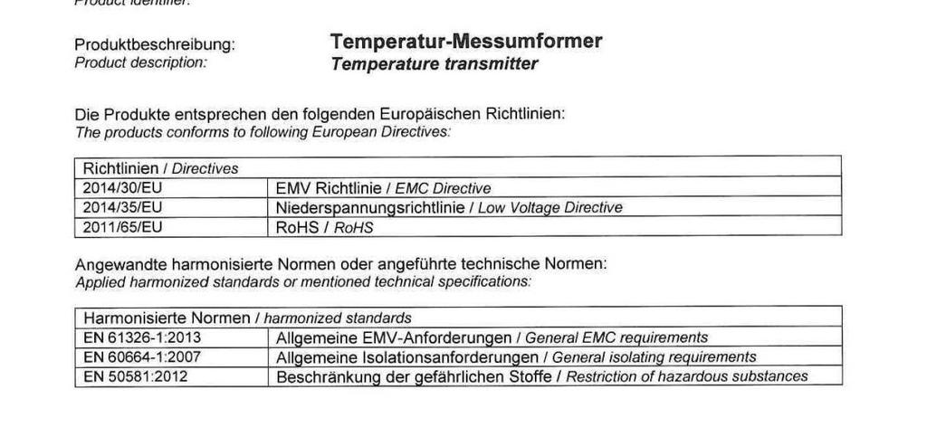
4 1.2 Safety instructions Read the product description before commissioning the device. Ensure that there are no limitations for use of the product for the relevant applications. DANGER The owner is responsible for ensuring the fault-free operation of the device. The owner is obligated to ensure compliance and to observe the required work and safety measures of the current applicable regulations for the entire duration of use. 1.3 Product liability and warranty Exclusion of liability: The contents of the operating manual have been checked to ensure conformity with the described device. However, deviations cannot be entirely ruled out. Therefore, we cannot assume any guarantee for complete conformity. The specifications in this document are checked regularly and any necessary corrections are incorporated into subsequent versions. This document is subject to technical changes. In addition, all claims are based on the valid 'Standard Terms for the Supply of Products and Services of the Electrical Industry'. GHM Messtechnik cannot inspect or repair any devices without the required form having been filled in completely (see chapter "Return"). 1.4 Standards and directives Low-voltage Directive 2014/35/EU Testing standard : 2007 EMC Directive 2014/30/EU Testing standard EN : 2013 RoHS Directive 2011/65/EU Testing standard EN50581: 2012 (Issue years for testing standards belong to german versions) 4
5 2. Product description Temperature measuring transducers of the series MU125 convert a temperature measurement value or resistance measurement value from various sensors to a current signal of 4..20mA. The universal configurability of the measuring inputs reduces the stock requirement for various applications. The measuring inputs and the analog output are galvanically isolated. The housing width of only 12.5mm enables space-saving installation in the switch cabinet Scope of delivery MU125 This operating manual Additional documents, if applicable 5
6 2.2. Functional principle An analog output value with ma is actuated depending on the selected measuring range. The temperature measuring ranges are linearised. The device configuration is carried out with DIP switches. The device can be supplied in a wide range between V DC or V AC. A low cost version with 24V DC power supply is available. Another version allows a 24V power supply via a mounting rail bus (Power Rail) Connection diagram The input signal should be connected via separate two-wire or threewire conductors. Earthed conductors can cause faults at an analog actual value output that is not galvanically isolated. 6

7 2.4. PowerRail The supply of multiple devices can be combined and simplified via a bus system in the carrier rail (TS35). A corresponding version is available for the entire LP series of GHM carrier rail devices in a housing with 12.5 mm width. A bus adapter compatible with series connection is clamped on the carrier rail before installation of the device to be supplied with power. An adapter is required for each device. The bus power supply is provided via a plug-type terminal strip. The power supply terminals 11 and 12 on the upper device side are omitted in device version MU125LP designed for this purpose. 7

8 2.5. Type plate The type plate provides the most important identification data Type and article designation Technical data Serial number / bar code Fig. 3: Type plate 8
9 3. Assembly and installation 3.1. Mechanical assembly Fig. 4 Carrier rail mounting TS35, DIN EN The gapless installation of multiple devices is only possible with a horizontally installed carrier rail Electrical installation DANGER The device may only be installed by an electrician. Compliance with the national and international regulations for installation of electrical and electronic systems applicable in the respective country of use is mandatory. Voltage supply in accordance with DIN EN , SELV, PELV. Observe the connection diagram for installation of inputs and outputs. The supply voltage connection is made at connections 11 and 12 of the plug-type terminal strip. Terminals 41, 42, 51 and 52 are provided for sensor connection Terminals 61 and 62 are provided for analog true value output 9
: Errors at the measuring inputs In service mode Red continuous light: Red rapid blinking: Green rapid blinking: The")
 Position of the trim potentiometer is positioned above the calibrated factory setting.")
10 4. Functional description 4.1 Controls Operation LED states Green continuous light: Normal operation. Red slow blinking (one-second frequency): Errors at the measuring inputs In service mode Red continuous light: Red rapid blinking: Green rapid blinking: The trim potentiometer is positioned at the factory setting. (red light differs from normal operation) Position of the trim potentiometer is positioned above the calibrated factory setting. Turn anti-clockwise to reach the factory setting. Position of the trim potentiometer is positioned below the calibrated factory setting. Turn clockwise to reach the factory setting. 10

 by +/- 40% based on the factory measuring range")
11 The measuring range is selected with the DIP switches: Pt100, Pt1000, thermocouple (type J, type K, type S), NTC and linear resistance. The black fields symbolise the position of the DIP switch Sensor break and sensor short circuit Monitoring for sensor breaks and short circuits also takes place in the measuring ranges for Pt100 and Pt1000 sensors. In this case, the relays become inactive and the scale light blinks red. The analog output drops to approx. 0mA. Trim potentiometer The 12-turn trim potentiometer can and reduce the end value by 50% change the zero point (start value) by +/- 40% based on the factory measuring range (= factory end value - factory start value) 11

12 There is also a service mode for the trim potentiometer offering the following possibilities: a) A check of whether potentiometers are positioned at the calibrated factory settings b) The pre-adjustment of a new output characteristic curve with connection of a current measuring device. (A temperature calibrator is not necessary) c) Specification of a constant value at the current output, e.g. in order to test the reaction of connection devices. The trim potentiometers can be used in both normal operation and service mode. 4.2 Service mode A corresponding service mode can be selected for each of the two trim potentiometers via the DIP switches Check of factory settings - If the selected potentiometer is positioned at the calibrated factory setting, the operation LED illuminates red (continuously). - If the potentiometer is above the calibrated factory setting, the operation LED blinks red. - If the potentiometer is below the calibrated factory setting, the operation LED blinks green. (Since the end value can only be reduced, the green blinking is omitted) 12
13 4.22 Output characteristic curve specification Settings for a deviating measuring range can be made without using a temperature calibrator For this purpose, the respective trim potentiometer is coupled directly to the analog output and generates a current proportional to the setting. Value range The current output can basically generate a current in the range of 4..20mA. The current range is thus 16mA. (20mA minus 4mA) As a result, the following classifications arise for a current change: A change of the input signal by results in an output voltage change of 100% 50% 40% 30% 20% 10% 1% 16mA 8mA 6.4mA 4.8mA 3.2mA 1.6mA 0.16mA The position of the assigned trim potentiometer simulates the input signal in the 2 service modes. Reduction of the measuring range end value The measuring range end value can be reduced by up to 50% below the factory end value. This process is simulated in service mode with an output current controlled by the trim potentiometer. Without reduction of the factory end value, which corresponds to the end position of the trim potentiometer, a constant current of 20mA is provided at the output in service mode. The operation LED then illuminates red (continuous light). The - trim potentiometer must be turned clockwise *) for a reduction of the measuring range end value. The operation LED then blinks red. According to the table above, for reducing the end value by - 20% the output current must be reduced by 3,2mA down to 16,8mA - 50% the output current must be reduced by 8mA down to 12mA *) The clockwise rotation is based on the behaviour in normal measuring operation: The output current based on the actual value increases with clockwise rotation,but this results in a smaller measuring range. 13
14 Change of the measuring range start value The start value can be changed by +/-40% based on the factory measuring range (= factor end value - factor start value). In order to show the potential change of the start value on the output current range, a virtual zero point of 12mA *) is assumed. This output current is generated in service mode if the trim potentiometer is positioned at the calibrated factory setting. The trim potentiometer is then in the centre position. The operation LED illuminates red (continuous light). *) If the factory zero point were based on 4mA, the output current for the simulation of a reduction by 40% would have to be negative, which is not technically possible According to the value range table on the preceding page, for a change of the start value by -40% the output current must be reduced by turning anticlockwise 6.4mA down to 5.6mA (12mA - 6.4mA = 5.6mA) -10% the output current must be reduced by turning anticlockwise 1.6mA down to 10.4mA (12mA - 1.6mA = 10.4mA) +10% the output current must be increased by turning clockwise 1.6mA up to 13.6mA (12mA + 1.6mA = 13.6mA) +40% the output current must be increased by turning clockwise 6.4mA up to 18.4mA (12mA + 6.4mA = 18.4mA) The operation LED blinks green with a reduction and red with an increase. Note: The device can only detect a minimum measurement temperature of -50 C in most measuring ranges (refer to "Technical data" for more information). Therefore, a reduction of the start value by -40% only makes sense in the factory measuring ranges of C, C and C. However, since the device can not recognise the measuring range to be applied later after leaving the service mode, a reduction by -40% can always be adjusted in this mode. In reality the device would switch off the output if the measuring temperature is too low (approx. 0mA). Examples 1) A measuring range of C should be changed to C. For this purpose, the factory end value must be reduced by 20% (1-400 C / 500 C = 0.20 = 20%). The value range table on the previous page shows that in service mode a reduction of the output current by 3,2mA must take place. Therefore, an output current of 16.8mA must be adjusted (20mA 3.2mA = 16.8mA) in service mode by the trim potentiometer. In service mode for the trim potentiometer the factory setting of 12mA should be left. 14
15 2) A measuring range of C should be changed to C. For this purpose, the measuring range end value must be reduced by 40%. (1-60 C / 100 C = 0.4 = 40%) Based on the value range table on page 13, the output current must be reduced (in service mode) by 6.4mA for a reduction of the end value by 40%. Therefore, an output current of 13.6mA must be adjusted (20mA 6.4mA = 13.6mA) with the trim potentiometer. To calculate the adjustment for the measuring range start value, the factory measuring range is determined first (factory end value - factory start value): 100 C 0 C = 100 C. (negative start values must be added because of the double sign) The measuring range start value should then be reduced by 25 C based on the measuring range, which then also necessitates a reduction of the output current by 25% in service mode. This value is multiplied by the greatest possible current change of 16mA: 16mA * 25% = 4mA Therefore, an output current of 8mA must be adjusted in service mode for the trim potentiometer. (virtual zero point at 12mA minus 4mA reduction = 8mA) Accuracy A reduction of the end value or an increase of the start value always reduces the measuring accuracy. The (in)accuracy values specified in the "Technical data" thus increase by the factor: factory end value factory start value (adjusted end value) (adjusted start value) (negative start values must be added because of the double sign) 4.23 Current simulation (divided by) The change of the output current proportional to the trim potentiometer setting in service mode can also be used to simulate an action which should appear in normal mode. An output current in the range of 5.6mA to 18.4mA can be simulated with the potentiometer. The 20mA. potentiometer can simulate an output current in the range of 10mA to After the simulation, the potentiometers must then be turned back to the original position, i.e. the factory setting. 15
16 5. Commissioning, maintenance and service 5.1 Commissioning 1. Ensure that the connections have been made as indicated in the connection diagram and the supply voltage is correct. 2. Ensure that the terminals are firmly screwed in. 3. After switching on the power supply, check to ensure the operation. 5.2 Maintenance Housing: No cleaning or maintenance is required when operated as intended. 5.3 Service Service of the device is only possible in the factory. 16
17 6. Technical data Wide-range power supply Supply voltage : VDC and VAC (47..63Hz), max.1.5w 24V power supply Supply voltage : 24V DC +/-15%, max. 1.5W Combined data Rated voltage- : 253V AC (in accordance with EN ; Degree of contamination 2, Overvoltage category II) Test voltage : 3kV AC between supply voltage // input = output Working temperature : C Storage temperature : C Air humidity : % (no condensation) EMC : in accordance with EN Measurement inputs Pt100 : linearised, Measuring current approx. 1.6mA Pt1000 : linearised, Measuring current approx. 130µA In the event of a sensor break or short circuit, the analog output drops to 0mA. The operation LED blinks red Thermocouple : linearised with comparison position compensation (optionally without internal compensation) NTC : linearised for B25/85=3977K or 3528K Max. load 200µW (averaged) Linear resistance : MR. 0..2kΩ: approx. 1.4mA MRs. 0..5kΩ, 0..10kΩ: approx. 300µA Zero point setting : +/-40% of the factory measuring range (= end value start value) via 12-turn trim potentiometer End value reduction : -50% based on the factory end value via 12-turn trim potentiometer Potentiometer : Limitation of the aforementioned adjustment ranges setting limits Pt C (..600 C) Pt C (..300 C) FeCuNi C (..800 C) NiCrNi C PtRhPt C ( C) NTC (10kΩ) C (..150 C) NTC ( 2kΩ) C (-50 C..150 C) R linear 0..10kΩ (values in parentheses apply for optional, customer-specific special measuring ranges that are configured at the factory) 17
18 Analogue output : 4..20mA, max. burden 400Ω, No galvanic isolation from the input signal (max. burden error of 0.2% at 400Ohm) Measuring Basic Temperature range accuracy deviation *) Pt C 0.4% 0.01%/K C 0.6% 0.02%/K C 0.4% 0.02%/K C 0.4% 0.01%/K C 0.3% 0.01%/K C 0.3% 0.01%/K C 0.2% 0.005%/K C 0.2% 0.005%/K Pt C 0.4% 0.01%/K C 0.4% 0.01%/K C 0.4% 0.01%/K C 0.6% 0.02%/K C 0.4% 0.02%/K C 0.4% 0.01%/K C 0.3% 0.01%/K C 0.3% 0.005%/K FeCuNi C 1.0% 0.04%/K C 0.5% 0.03%/K NiCrNi C 0.7% 0.05%/K C 0.5% 0.04%/K C 0.4% 0.03%/K C 0.3% 0.02%/K C 0.3% 0.02%/K PtRhPt C 1.0% 0.04%/K NTC C 1.0% 0.01%/K R25=10kΩ B25/85=3977K NTC C 1.5% 0.01%/K R25=10kΩ B25/85=3977K NTC R25=2kΩ C 1.0% 0.01%/K B25/85=3528K Resistance linear 0.. 2kΩ 0.3% 0.005%/K 0.. 5kΩ 0.5% 0.01%/K 0..10kΩ 0.3% 0.005%/K *) Measurement deviation depending on the environmental temperature in the switch cabinet ( C) 18
19 Casing Dimensions (WxDxH) Material Weight Protection rating Screw terminals Push-in terminals (spring-type terminals) Power Rail : 12.5 x 114 x 108 mm : PA6.6, light grey, Flammability class V0 (UL94) : 120 g : IP20 : mm², AWG 24-14, removable, coded : mm², AWG 25-16, double connection (12A between the connections), removable, coded : 8A over the entire bus system (power supply via removable terminals mm², AWG ) 6.1 Mechanical design / dimensions 19
20 7. Order code MU - 1. Device version 125L Supply voltage 24V DC +/- 15% 125LP Supply voltage:24v DC +/- 15% with carrier rail bus connection *) 125M Wide-range power supply VDC / V AC 4. Options 00 No options 01 Push-in terminals (plug-in) *) Delivery incl. suitable bus adapter, see also chapter "PowerRail" 8. Device transport and storage Gentle and tension-free packaging of the housing must be ensured for transport (no machine wrapping of the package). The device must be stored in the environmental conditions specified in the technical data. 20

21 9. Return to manufacturer DANGER The legal regulations for environmental protection and our personnel require that devices which are sent back which have come into contact with liquid are handled without risk to people or the environment. If you send a device back to us for inspection or repair, we must request that you strictly observe the following requirements: On the GHM homepage under: 'Downloads/forms' a return shipment form can be downloaded. The repair can be performed quickly and without call-back questions if: 1. a filled-in form is provided for each device, 2. the device has been cleaned and packaging which prevents damage to the device is used, and 3. a safety data sheet for the measuring medium is affixed to the outside of the package, if the device has come into contact with a critical substance. 10. Disposal Separation by material and recycling of device components and packaging must take place when the device is disposed of. The valid legal regulations and directives applicable at the time must be observed. The device may not be disposed of with household waste. If the device should be disposed of, return it to us with the return shipment form filled in under the chapter "Return". We will then arrange for the proper disposal. 11 Imprint GHM Messtechnik GmbH Standort Martens, Kiebitzhörn 18, Barsbüttel, Germany Managing Director: Günther Oehler Registered office: Schloßstr. 6, Erolzheim / Germany Amtsgericht Ulm, Commercial Register Section B Copyright: GHM Messtechnik GmbH. All rights reserved. Reprints, digital use of any type, and duplication may only take place with the written authorisation of GHM Messtechnik GmbH. 21

22 12. Certificate of Conformity 22
23 23
24 V
Transmitter / Signal Conditioning
 GHM GROUP CORPORATE GHM Messtechnik GmbH Schloßstr. 6 88453 Erolzheim GERMANY Phone +49 7354 937233-76 Fax +49 7354 937233-88 Transmitter / Signal Conditioning System Measuring input Direct connection
SIMEAS-T. Operating Instructions Transducer without auxiliary power. 7KG6111 and 7KG6101. Operating Instructions
 Operating Instructions SIMEAS-T s Operating Instructions Transducer without auxiliary power for alternating current for alternating voltage for alternating voltage with expanded end range 7KG6111 and 7KG6101
Operating Manual * * Differential pressure transmitter. Table of Contents. 1 Safety guidelines. 1.1 General Information
 *09005137* BA_EN_DE50 Rev.A 11/12 *09005137* d e v e l o p i n g s o l u t i o n s DE50 Operating Manual Differential pressure transmitter Table of Contents 1 Safety guidelines 2 Application purpose 3
Operator Manual. Transmitters Series KAT-... Analog transmitters in 2-wire technique
 Operator Manual Transmitters Series KAT-... Analog transmitters in 2-wire technique Important Safety Notes! In the case of non-observance of the installation and safety notes or improper use of the transmitter
OPTITEMP TT 20 Technical Datasheet
 OPTITEMP TT 20 Technical Datasheet Analog PC-programmable two-wire transmitters for Pt100 Efficient PC-configuration without recalibration Very stable output Very fast response time The documentation is
Thermocouple - Transducer
 Thermocouple - Transducer TM3 Characteristics: Thermocouple type J, K, R, S, T, E, B, N Linearity error < 1% Measurement range configurable -210...+1820 C Built-in cold junction compensation Galvanic 3-way
DT1100 E xx xx (PS) Galvanic Isolators. Operating Instructions
 Galvanic Isolators. Operating Instructions") DT1100 E xx xx (PS) Galvanic Isolators Operating Instructions Contents 1. About this document...4 1.1. Function... 4 1.2. Target group... 4 1.3. Symbolism used... 4 2. For your safety...5 2.1. Authorized
DT1100 E xx xx (PS) Galvanic Isolators Operating Instructions Contents 1. About this document...4 1.1. Function... 4 1.2. Target group... 4 1.3. Symbolism used... 4 2. For your safety...5 2.1. Authorized
Intrinsically Safe Compact Controller CTR 210i. Intrinsically Safe Bargraph Indicator. BGI 210i
 Intrinsically Safe Compact Controller CTR 210i Intrinsically Safe Bargraph Indicator BGI 210i DMT 02 ATEX E 148 2. Supplement also grahics display Revision 4 IBS BatchControl GmbH Im Sträßchen 2 4 Tel.:
Operating manual GTL 241 GTL 251. Temperature probe. Please keep the manual for future use.
 Operating manual Temperature probe GTL 241 GTL 251 Please keep the manual for future use. L01.0.2X.6C-02 GREISINGER electronic GmbH Hans-Sachs-Str. 26 93128 Regenstauf Germany Fon +49(0)9402-9383-0 Fax
DT1100 xx xx xx PS. Isolators, Isolator / Power Supplies. Operating Instructions
 Isolators, Isolator / Power Supplies Operating Instructions EN Contents 1. About this document...4 1.1. Function... 4 1.2. Target group... 4 1.3. Symbolism used... 4 2. For your safety...5 2.1. Authorized
CONTA-ELECTRONICS. Converter Units
 CONTA-ELECTRONICS Whether for manufacturing, electrical machine and plant instrumentation, control engineering, power distribution, building automation, or process engineering it is always important to
Instruction Manual MSC710 MSC710-U MSC710-I
 Instruction Manual MSC710 MSC710-U MSC710-I Sensor controller for inductive displacement and gauging sensors series LVDT MICRO-EPSILON MESSTECHNIK GmbH & Co. KG Koenigbacher Strasse 15 94496 Ortenburg
JUMO dtrans T04 Four-wire Transmitter, settable via DIP switch/pc setup program
 JUMO GmbH & Co. KG Delivery address:mackenrodtstraße 14, 36039 Fulda, Germany Postal address: 36035 Fulda, Germany Phone: +49 661 6003-0 Fax: +49 661 6003-607 e-mail: mail@jumo.net Internet: www.jumo.net
Documentation. Measurement and Control. Type: ELT-GP2
 Documentation Measurement and Control Type: ELT-GP2 05.01.2018 K. Folkerts Content 1. Data sheet 2. Installation instructions 3. Declarations of conformity 05.01.2018 K. Folkerts 1 05.01.2018 K. Folkerts
Isolators A3/1. Temperature Transmitter Field Circuit Non-Ex i Series
 Temperature Transmitter Series 9182 > One unit for nearly all temperature sensors indivdually configurable > Signal duplication possible > Galvanic isolation between input, output, power supply and configuration
Documentation. Content. Measurement and Control. Type: ELT-GP1. 1. Installation instructions 2. Data sheets 3. Declarations of conformity
 Documentation Measurement and Control Type: ELT-GP1 Content 1. Installation instructions 2. Data sheets 3. Declarations of conformity (Part No. 008Q520) eltherm GmbH Ernst-Heinkel-Str. 6-10 57299 Burbach
USER S MANUAL POWER SUPPLY - ISOLATOR - SIGNAL CONVERTER ZSP 41 POWER SUPPLY - ISOLATOR - SIGNAL CONVERTER SIGNAL MULTIPLIER ZSP 41/2
 (ENG) DECEMBER 2017 USER S MANUAL POWER SUPPLY - ISOLATOR - SIGNAL CONVERTER ZSP 41 POWER SUPPLY - ISOLATOR - SIGNAL CONVERTER SIGNAL MULTIPLIER ZSP 41/2 ISOLATOR - SIGNAL CONVERTER TYPE SP 11 CURRENT
MINI-PS AC/24DC/1.3
 Power supply unit INTERFACE Data sheet 102894_en_03 1 Description PHOENIX CONTACT 2015-11-17 Features MINI POWER power supplies for MCR technology In measurement and control technology (MCR), modular electronics
SEPARATOR P20G TYPE USER S MANUAL
 SEPARATOR P20G TYPE USER S MANUAL 1 2 Contents 1. APPLICATION... 5 2. SEPARATOR SET... 5 3. OPERATIONAL SAFETY... 6 4. FITTING... 7 4.1. Fixing Way... 7 4.2. External Connection Diagrams... 8 5. SERVICE...
High-quality digital indicator for panel mounting Model DI35-M, with multi-function input Model DI35-D, with two inputs for standard signals
 Accessories Highquality digital indicator for panel mounting Model DI35M, with multifunction input Model DI35D, with two inputs for standard signals WIKA data sheet AC 80.03 Applications Machine building
Process displays For standard signals, temperature, resistance measurement
 Features Inputs: Voltage ±10 V, ±200 V / Current ±20 ma / thermocouples J,K,T,N,Pt100,Pt1000 / resistance measurement / potentiometer Display range can be linearised Two limits output Min, Max functions
Temperature Input Module for Zone 1 Series 9482/32
 www.stahl.de > 8 channels for temperature sensors > Intrinsically safe inputs Ex ia > For Pt-, Ni- and Cu-resistance temperature detectors according to DIN, IEC and GOST in 2-, 3- and 4-wire circuits >
Level Switch NRS 2-50 NRS Original Installation Instructions English
 Level Switch NRS 2-50 NRS 2-51 EN English Original Installation Instructions 819179-03 1 Contents Important Notes Page Usage for the intended purpose...4 Function...4 Safety note...4 Directives and Standards
MODEL AT-10 ANALOG TRANSMITTER
 MODEL AT-10 ANALOG TRANSMITTER INSTALLATION & OPERATING MANUAL Industrial Weighing Systems 9 Richmond Street Picton, Ontario K0K 2T0 Phone: 613-921-0397 Fax: 613-476-5293 Web: www.iwsystems.ca info@iwsystems.ca
Operating Manual MU2000K
 ZIEHL industrie elektronik GmbH + Co KG Daimlerstr.13, 74523 Schwäbisch Hall, Germany + 49 791 504-0, info@ziehl.de, www.ziehl.de Temperature Relays and MINIKA Mains Monitoring Digital Panelmeters MINIPAN
Isolators A3/1.
 Temperature Transmitter Series 9182 > One unit for nearly all temperature sensors indivdually configurable > Signal duplication possible > Galvanic isolation between input, output, power supply and configuration
JUMO di 32 / di 08. Brief description. Block structure
 M. K. JUCHHEIM GmbH & Co Delivery address:mackenrodtstraße 14, 36039 Fulda, Germany Postal address: 36035 Fulda, Germany Phone: +49 (0) 661 60 037 25 Fax: +49 (0) 661 60 036 81 EMail: mail@jumo.net Internet:
Out 1 sin / cos 1Vpp. sin / cos 1Vpp. Out 3. sin / cos 1Vpp. Out 4 sin / cos 1Vpp. Interface type SV211 SinCos signal splitter with 4 SinCos outputs
 Operating Manual Out 1 sin / cos 1Vpp Input: sin / cos 1 Vpp Out 2 sin / cos 1Vpp Out 3 sin / cos 1Vpp SV 211 Out 4 sin / cos 1Vpp Interface type SV211 SinCos signal splitter with 4 SinCos outputs Product
MINI MCR-SL-UI-I-LP-NC
 2-way isolation amplifier Data sheet 105263_en_02 PHOENIX CONTACT 2013-12-13 1 Description The configurable 2-way isolation amplifiers are used to electrically isolate, convert and filter standard signals.
Radio System Strobe Wizard Plus Freemask
 Radio System Strobe Wizard Plus Freemask User manual Translation of the original German user manual Doc. No.: 900.0509.00 Version: 09/2017 Contents Information about this manual and about the manufacturer...
ABB i-bus EIB / KNX Analogue Input AE/S 4.2
 Product Manual ABB i-bus EIB / KNX Analogue Input AE/S 4.2 Intelligent Installation Systems This manual describes the functionality of Analogue Input AE/S 4.2. Subject to changes and errors excepted. Exclusion
3B SCIENTIFIC PHYSICS
 3B SCIENTIFIC PHYSICS Digital Multimeter E 1018832 Instruction sheet 12/16 SD/UD 1 probe 1a Finger guards 2 Measurement socket 10 A for current measurement in 10-A (positive) 3 Measurement socket COM (negative)
Precipitation Monitor ,
 THE WORLD OF WEATHER DATA - THE WORLD OF WEATHER DATA - THE WORLD OF WEATHER DATA Instruction for use 021197/11/09 Precipitation Monitor 5.4103.10.000, 5.4103.10.700 ADOLF THIES GmbH & Co. KG Hauptstraße
High-quality digital indicator for panel mounting Model DI35-M, with multi-function input Model DI35-D, with two inputs for standard signals
 Accessories High-quality digital indicator for panel mounting Model DI35-M, with multi-function input Model DI35-D, with two inputs for standard signals WIKA data sheet AC 80.03 Applications Machine building
Original operating instructions Fail-safe inductive sensor GM504S / / 2010
 Original operating instructions Fail-safe inductive sensor GM504S 704070 / 01 06 / 2010 Contents 1 Preliminary note 3 1.1 Explanation of symbols 3 2 Safety instructions 4 2.1 Safety-related requirements
TRANSDUCER of TEMPERATURE and STANDARD SIGNALS P20 type
 TRANSDUCER of TEMPERATURE and STANDARD SIGNALS P20 type USER S MANUAL Contents 1. APPLICATION...5 2. TRANSDUCER SET...5 3. OPERATIONAL SAFETY...6 4. INSTALLATION...7 4.1. Fitting way...7 4.2. External
Installation and Operational Instructions for ROBA -switch Type 017._00.2
 OBA -switch Type 017._00.2 Guidelines on the Declaration of Conformity A conformity evaluation has been carried out for the product in terms of the EC Low Voltage Directive 2014/35/ EC and the EMC Directive
Power supply CP-D 24/4.2 Primary switch mode power supply
 Data sheet Power supply CP-D 24/4.2 Primary switch mode power supply The CP-D range of modular power supply units in MDRC design (modular DIN rail components) is ideally suited for installation in distribution
Section 1, General information Introduction... 3 Description... 3 Specifications... 4 Wiring connections... 5
 LIST OF CONTENTS Section 1, General information Introduction... 3 Description... 3 Specifications... 4 Wiring connections... 5 Section 2, Calibration Calculations... 7 Calibration Procedure... 8 Section
CDG. Carbon Dioxide - User Manual Gas Detector. 1 Intended Use. 2 Functional Description. 3 Installation. 4 Electrical Connection.
 Carbon Dioxide - User Manual 1 Intended Use 2 Functional Description 2.1 Control Mode 2.2 Sensor 3 Installation 3.1 Mounting instructions 3.2 Installation 4 Electrical Connection 4.1 Instruction 5 Commissioning
Technical Documentation
 Technical Documentation PROAM-21 Power amplifier for directional valves Grundlage der Funktionsbeschreibung und zur Prüfung der Module (keine Produktdokumentation). AMCA HYDRAULIC FLUID POWER B.V. P.O.BOX
OPTITEMP TT 10 C/R Technical Datasheet
 OPTITEMP TT 10 C/R Technical Datasheet Analogue 2-wire temperature transmitter Temperature linear 4...20 ma output Rangeable with solder pads and potentiometers Easy wiring through large center hole The
Melt pressure Transmitter GREENLINE Type DTAI with Temperature element
 Melt pressure Transmitter GREENLINE Type DTAI with Temperature element Operation and Maintenance Manual English Mercury free NaK free Seite 1 / 9 Contents: 1. Introduction 2. Operating range and field
Installation and Operational Instructions for ROBA -multiswitch Type 019._00.2
 Guidelines on the Declaration of Conformity A conformity evaluation has been carried out for the product in terms of the EU Low Voltage Directive 2014/35/ EU and the Electromagnetic Compatibility (EMC)
Operating Instructions / Voltage Tester per IEC with Phase and Polarity Tester and Phase Sequence Indicator
 Operating Instructions 3-349-298-15 3/11.09 METRAVOLT 7A Voltage Tester per IEC 61243-3 with Phase and Polarity Tester and Phase Sequence Indicator CAT IV GMC-I Messtechnik GmbH Südwestpark 15 90449 Nürnberg
MU110-16R(K) Digital output module 16 channel. User guide
 Digital output module 16 channel. User guide") MU110-16R(K) Digital output module 16 channel User guide MU110-16R(K)_2016.12_0220_EN All rights reserved Subject to technical changes and misprints akytec GmbH Vahrenwalder Str. 269 A 30179 Hannover Germany
MU110-16R(K) Digital output module 16 channel User guide MU110-16R(K)_2016.12_0220_EN All rights reserved Subject to technical changes and misprints akytec GmbH Vahrenwalder Str. 269 A 30179 Hannover Germany
Operating Instructions PROFITEST H+E TECH. Diagnostics Unit for Electric Charging Stations (Type 2 Connector Socket and Plug) /3.
 /3.") Diagnostics Unit for Electric Charging Stations (Type 2 Connector Socket and Plug) 3-349-878-03 1/3.16 Opening the Instrument / Repairs The instrument may only be opened by authorized, trained personnel
Diagnostics Unit for Electric Charging Stations (Type 2 Connector Socket and Plug) 3-349-878-03 1/3.16 Opening the Instrument / Repairs The instrument may only be opened by authorized, trained personnel
DIGITAL PANEL METER N24 AND N25 METER SERIES
 DIGITAL PANEL METER N24 AND N25 METER SERIES USER S MANUAL Contents 1. APPLICATION...5 2. METER SET...5 3. OPERATIONAL SAFETY...6 4. INSTALLATION...7 4.1 Fixing Way...7 4.2 External Connection Diagrams...8
RAD-IN/OUT-8D. Digital extension modules for the bidirectional wireless system. INTERFACE Data sheet _en_05. 1 Description
 RAD-IN/OUT-D Digital extension modules for the bidirectional wireless system INTERFACE Data sheet 102122_en_0 PHOENIX CONTACT 2010-02-2 1 Description The RAD-ISM-...-SET-BD-BUS-ANT bidirectional wireless
CM605. User Manual AC/DC LOW CURRENT CLAMP-ON METER ENGLISH
 AC/DC LOW CURRENT CLAMP-ON METER CM605 ENGLISH User Manual Statement of Compliance Chauvin Arnoux, Inc. d.b.a. AEMC Instruments certifies that this instrument has been calibrated using standards and instruments
DUAL OUTPUT AC CURRENT/VOLTAGE TRANSDUCER
 OPERATOR S MANUAL DUAL OUTPUT AC CURRENT/VOLTAGE TRANSDUCER Masibus Automation & Instrumentation Pvt. Ltd. B/30, GIDC Electronics Estate, Sector-25, Gandhinagar-382044, Gujarat, India Web Site: www..com
3 Ex i Isolators. Temperature Transmitter with Output 0/ ma, without Limit Value Contact (Field Circuit Ex i) Type 9182/.0-5.
 Type 9182/.0-5.") Ex i Isolators Temperature Transmitter with Output 0/4... 20 ma, without Limit Value Contact Field Circuit Ex i) One unit for nearly all temperature sensors indivdually configurable Intrinsically safe
Ex i Isolators Temperature Transmitter with Output 0/4... 20 ma, without Limit Value Contact Field Circuit Ex i) One unit for nearly all temperature sensors indivdually configurable Intrinsically safe
Signal converter for electromagnetic flowmeters
 Quick Start Signal converter for electromagnetic flowmeters Electronic revision: ER 3.0.xx The documentation is only complete when used in combination with the relevant documentation for the flow sensor.
Wireless Receiver E28Q Mounting and Operating Instructions (Original operating instructions)
") EN Wireless Receiver E28Q Wireless Receiver E28Q Mounting and Operating Instructions (Original operating instructions) Always read before initial operation! 28509900_E28Q_EN_2012-05-08.doc 1 / 12 1 Data
EN Wireless Receiver E28Q Wireless Receiver E28Q Mounting and Operating Instructions (Original operating instructions) Always read before initial operation! 28509900_E28Q_EN_2012-05-08.doc 1 / 12 1 Data
QUINT-PS-24DC/24DC/10
 QUINT-PS-24/24/10 QUINT - converter, primary switched mode, input: 24 V, output: 24 V /10 A INTERFACE Data Sheet PHOENIX CONTACT - 02/2006 Description The QUINT - converter 24 V/10 A converts the voltage
MV110-8AS. Analog input module 8 channel. User guide
 MV110-8AS Analog input module 8 channel User guide MV110-8AS_2016.12_0226_EN All rights reserved Subject to technical changes and misprints Contents 1 Description... 2 1.1 Function... 2 1.2 RS485 network...
Operating Instructions
 Level and Pressure Operating Instructions VEGATOR 620, 621, 622 max. 0 10 min. 0 10 on VEGATOR 622! 6 7 8 9 10 11 12 13 14 in out Contents Contents Safety information... 2 Note Ex area... 2 1 Product description
Calibration and Testing
 GHM GROUP CORPORATE GHM Messtechnik GmbH Schloßstr. 6 88453 Erolzheim GERMANY Phone +49 7354 937233-76 Fax +49 7354 937233-88 Features System Sources Measurement chain Strain gauge bridges Current signals
s Climatix extension module 26 I/Os POL985.00/XXX
 s 3 921 Climatix TM Climatix extension module 26 I/Os POL985.00/XXX The POL985.00/XXX extension module extends the number of I/Os of Climatix 600 controllers. It is a product of the Climatix range. The
Power supply CP-D 12/2.1
 2CDC 271 025 F0t07 a OUTPUT ++/ : terminals output Features Rated output voltage 12 V DC Output voltage adjustable via front face potentiometer OUTPUT Adjust Rated output current 2.1 A Rated output power
VariTrans P Compact automation solutions can be implemented thanks to the 17.5 mm modular housing and operation at temperatures up to 70 C.
 ProLine Interface Technology Transducers for High Voltage / Shunt Applications Compact high voltage transducers with VariPower broad-range power supply and genuine calibrated range selection. The Task
POWER TRANSDUCERS FOR SINGLE-PHASE AND THREE-PHASE NETWORK ISO P11P, P13P and P13B mm SERVICE MANUAL
 POWER TRANSDUCERS FOR SINGLE-PHASE AND THREE-PHASE NETWORK PP, PP and PB ISO 900 C E R T Y F I K A T 4 mm SERVICE MANUAL Contents Page. APPLICATION... 2. BASIC REQUIREMENTS.... TRANSDUCER SET... 4 4. TECHNICAL
MODEL 3810/2 Line Impedance Stabilization Network
 EMC TEST SYSTEMS FEBRUARY 1996 REV C PN 399197 MODEL 3810/2 Line Impedance Stabilization Network OPERATION MANUAL USA P.O. Box 80589 Austin, Texas 78708-0589 2205 Kramer Lane, Austin, Texas 78758-4047
Phase-sequence Phase-loss Relay
 Phase-sequence Phase-loss Relay K8AB-PH Three-phase Phase-sequence Phase-loss Relay Using Voltage Detection Method Prevents reverse motor rotation due to incorrect wiring. Distinguishes between positive
TVA 080 / 100 / 120 / 180 / 200 / 220 Isolation amplifier active
 Technical manual BA 0318 Signal converter Isolation amplifier active for galvanic isolation, conversion and adjustment of electrical standard signals Evaluable input signals Direct voltage 0...10V / 0...1V
Assembly. Front view. Parametrization interface. Power Bus
 Temperature Converter Features Assembly 1-channel signal conditioner 24 V DC supply Thermocouple, RTD, potentiometer or mv input Input for PTC thermistor Current and voltage output Line fault (LFD) and
External brake resistor AX2090-BW5x
 Documentation External brake resistor AX2090-BW5x Accessories for Beckhoff servo drive AX5000 Version: Date: 1.3 2018-03-14 Table of content Table of content 1 Foreword... 5 1.1 Notes on the documentation...
3B SCIENTIFIC PHYSICS
 3B SCIENTIFIC PHYSICS Analogue Multimeter Escola 100 1013527 Instruction sheet 12/15 SD/JS 1 Display with mirror scale 2 Slotted screw for zero calibration 3 Calibration trimmer for setting centre zero
SEM1600T RTD/TC/SLIDE WIRE SIGNAL CONDITIONER
 RTD, THERMOCOUPLE, THERMISTOR (BMS SENSORS), SLIDE WIRE, mv AND RESISTANCE INPUTS ma, VOLTAGE OR BIPOLAR VOLTAGE OUTPUT SENSOR OFFSET (TEMPERATURE) 22 SEGMENT USER LINEARISATION (PROCESS) CONFIGURATION
JUMO Wtrans Receiver Universal Receiver for JUMO Wireless Measuring Probes
 Data sheet 902931 Page 1/10 JUMO Wtrans Receiver Universal Receiver for JUMO Wireless Measuring Probes For processing physical measurands of the JUMO Wtrans series RS485 interface with Modbus protocol
Electronic Thermostat TE-1 Version according to EN
 JUMO GmbH & Co. KG Delivery address:mackenrodtstraße 14, 3639 Fulda, Germany Postal address: 3635 Fulda, Germany Phone: +49 661 63- Fax: +49 661 63-67 e-mail: mail@jumo.net Internet: www.jumo.net JUMO
SUNNY BEAM REPEATER Transmission Range Increase for Sunny Beam
 SUNNY BEAM REPEATER Transmission Range Increase for Sunny Beam User Manual SBeamRep-BEN091911 98-0002611 Version 1.1 EN SMA Solar Technology AG Table of Contents Table of Contents 1 Notes on this Manual..............................
ProfiScale MULTI Multimeter
 1,5 V 9V 200 mv 600 V 200 ma 1/10 A ProfiScale MULTI Multimeter en Operating instructions BURG-WÄCHTER KG Altenhofer Weg 15 58300 Wetter Germany Introduction Want the reassurance of knowing whether current
SINEAX V 624 Programmable Temperature Transmitter for RTD and TC inputs
 SINEAX V 6 for rail mounting in housing P/7 or P/7 St 00 II () GD Application SINEAX V 6 (Figs. and ) is designed for measuring temperature in combination with thermocouples or resistance thermometers.
JUMO Wtrans Receiver with Wireless Data Transmission
 Data Sheet 902931 Page 1/10 JUMO Wtrans Receiver with Wireless Data Transmission k For measuring temperature, pressure, potentiometer, and voltage. k Interface RS485 with Modbus protocol k Wireless measured
Precipition Sensor with analogue Intensity Output ,
 THE WORLD OF WEATHER DATA - THE WORLD OF WEATHER DATA - THE WORLD OF WEATHER DATA Instruction for use 021335/11/09 Precipition Sensor with analogue Intensity Output 5.4103.20.041, 5.4103.20.741 ADOLF THIES
Installation and Operating Manual
 GB Analog Weight Transmitter PS-1000 Installation and Operating Manual LIST OF CONTENTS Section 1, General information Introduction... 3 Description... 3 Specifications... 4 Wiring connections... 5 Section
The frequency inverter continues to carry hazardous voltages for up to 5 minutes after it was switched off.
 Getriebebau NORD GmbH & Co. KG Getriebebau-Nord-Straße 1 22941 Bargteheide, Germany www.nord.com o SK BRI4-1-200-100 Part number: 275 272 008 Internal braking resistor for connection to a NORDAC FLEX SK
Installation and Operating Instructions for Phase Demodulator Type _.2
 Guidelines on the Declaration of Conformity A conformity evaluation has been carried out for the product in terms of the EU Low Voltage Directive 2014/35/EU and the Electromagnetic Compatibility (EMC)
ADC5000 SERIES. AC/DC Switch Mode Power Supplies and Rectifiers for Industrial and Telecom Applications. 60W, 125W and 250 W
 ADC5000 SERIES AC/DC Switch Mode Power Supplies and Rectifiers for Industrial and Telecom Applications 60W, 125W and 250 W Input voltage 230/115 VAC voltages 12, 24, 36 or 48 VDC Statistical MTBF >3 000
2002-ALM USER MANUAL
 00 - ALM DUAL TRIP AMPLIFIER Whilst every effort has been taken to ensure the accuracy of this document, we accept no responsibility for damage, injury, loss or expense resulting from errors or omissions,
Power supply CP-E 24/2.5
 2CDC 271 015 F0t06 a OUTPUT L+, L : terminals output b DC OK: terminal signalling output c INPUT L, N, PE: terminals input d OUTPUT OK: green LED output voltage OK e OUTPUT Adjust: potentiometer adjustment
for installation into terminal head form B and for installation on DIN rail Output signals : 4 to 20 ma : 4 to 20 ma 0 to 10 V
 sales@jumo.co.uk info.us@jumo.net Page 1/12 JUMO dtrans T0 Programmable twowire transmitter for installation into terminal head form B and for installation on DIN rail Brief description The transmitters
Power supply CP-E 24/20.0
 2CDC 271 027 F0008 a OUTPUT L+, L+, L, L-: terminals output b INPUT L, N, PE: terminals input c 13-14: terminals - signalling contact d OUTPUT OK: green LED output voltage OK e OUTPUT LOW: red LED output
JUMO dtrans T01 HART / T01T HART / T01 Junior / T01 Ex / T01 HART Ex Programmable 2-wire transmitter
 JUMO GmbH & Co. KG Delivery address: Mackenrodtstraße 14 36039 Fulda, Germany Postal address: 36035 Fulda, Germany Phone: 49 661 60030 Fax: 49 661 6003607 Email: mail@jumo.net Internet: www.jumo.net JUMO
PRetrans Table of contents
 HART TRANSPARENT REPEATER PRetrans 5106 Table of contents Warnings 16 Safety instructions 17 EC Declaration of Conformity 19 How to demount SYSTEM 5000 20 Application 21 Technical characteristics 21 Mounting
itemp HART DIN rail TMT112
 Temperature transmitter itemp HART DIN rail TMT112 Universal temperature transmitter for resistance thermometers (RTD), thermocouples, resistance and voltage transmitters, incorporating HART protocol Application
PU202 Level converter & encoder signal generator without potential separation
 Operating Manual PU202 Level converter & encoder signal generator without potential separation Product features: Converts HTL signals from 10 up to 30 V (A / B / Z) into the corresponding TTL / RS422 format
DSCL, DSCP, SCTP. Industrial Loop Isolators and Transmitters DSCL, DSCP, SCTP. Industrial Loop Isolators and Transmitters
 Industrial Loop Isolators and Transmitters DSCL,, SCTP DSCL,, SCTP Industrial Loop Isolators and Transmitters Description Dataforth s DSCL,, and SCTP series of products is a complete family of loop and
MINI MCR-SL-UI-f(-SP)
") Configurable Analog Frequency Transducer INTERFACE Data Sheet PHOENIX CONTACT - 02/2006 Description The configurable analog frequency transducer MINI MCR-SL-UI-f(-SP) is used to convert analog standard
Configurable Analog Frequency Transducer INTERFACE Data Sheet PHOENIX CONTACT - 02/2006 Description The configurable analog frequency transducer MINI MCR-SL-UI-f(-SP) is used to convert analog standard
MCR-VAC-UI-0-DC. Voltage transducer for AC voltages. INTERFACE Data sheet _en_02. 1 Description
 Voltage transducer for AC voltages TERFACE Data sheet 006_en_0 PHOENIX CONTACT 00-0- Description The MCR voltage transducer measures AC voltages in several signal ranges from 0... ±4 V AC to 0... ±30 V
09746E00. ATEX / IECEx NEC 505 NEC 506 NEC 500 Class I Class I Class II Class III Zone Zone Division Ex i
 Temperature Transmitter Series 9182 www.stahl.de > One unit for nearly all temperature sensors indivdually configurable > Intrinsically safe input [Ex ia] IIC > Signal duplication possible > Galvanic isolation
Operator s Manual. PP016 Passive Probe
 Operator s Manual PP016 Passive Probe 2017 Teledyne LeCroy, Inc. All rights reserved. Unauthorized duplication of Teledyne LeCroy documentation materials is strictly prohibited. Customers are permitted
Temperature transmitter itemp PCP DIN rail TMT 121
 Technical information TI 087R/09/en 510 03671 Temperature transmitter itemp PCP DIN rail TMT 121 Universal temperature transmitter for resistance thermometers (RTD), thermocouples, resistance and voltage
MCR-SL-CUC Universal current transducer. Data sheet _en_05. 1 Description
 Universal current transducer Data sheet 104059_en_05 PHOENIX CONTACT 2011-03-09 1 Description MCR-SL-CUC-...-I and MCR-SL-CUC-...-U active current transducers convert DC, AC, and distorted currents into
Industrial motor controller for brushed DC motors 24 VDC
 Industrial motor controller for brushed DC motors 24 VDC Design for output currents up to 5 A Control with the following functions: - reversal of direction of rotation - open-loop speed control (external)
Operating Instruction
 Level and Pressure Operating Instruction VEGASEL 643 6 5 + + 3 5 + + max. min. on VEGASEL 643 5 6 7 8 9 10 11 12 13 14 in out Contents Contents Safety information... 2 1 Product description 1.1 Function
N24, N25 DIGITAL PANEL METER
 DIGITAL PANEL METER www.sifamtinsley.co.uk USER S MANUAL Multifunction Meters Transducers & Isolators Temperature Controllers Converters & Recorders Digital Panel Meters DIGITAL PANEL METER Current Transformers
Operating instructions Fail-safe delay timer AZS About this document. Content
 8 Appendix 8.1 Wiring example...4 8.2 Integral System Diagnostics (ISD)....5 9 EU Declaration of conformity Operating instructions.............pages 1 to 6 Original x.000 / 11.2017 / v.a. - 101126753-
5 years! Modular Housings. VariTrans P Warranty
 Modular Housings VariTrans P 27000 The Multimeter among the isolators. With 480 switchable calibrated ranges and broad-range power supply. The Task A wide range of measuring signals need to be galvanically