Communication Systems Lab Manual
|
|
|
- Jasper Pitts
- 6 years ago
- Views:
Transcription

1 SWEDISH COLLEGE OF ENGINEERING & TECHNOLOGY Communication Systems Lab Manual Submitted by: Roll No.: Board Roll No.: Submitted to: Ahmad Bilal
2

3 COMMUNICATION SYSTEMS Table of Contents SAMPLING Understanding of ST2101 Experiment No 01 Study of Signal Sampling Experiment No 02 Study of Sample & Hold Signal Experiment No 03 PULSE MODULATION Study of Pulse Amplitude modulation Experiment No 04 Study of PAM Sample & Hold Sampling Experiment No 05 Study of Pulse Amplitude modulation & Demodulation Experiment No 06 Study of PAM Using DC Input Experiment No 07 Study of PPM Using Sin Wave Input Experiment No 08 Study of PPM Demodulation Experiment No 09
4 Study of PWM Using DC Voltage Experiment No 10 Study of Voice Link Using Pulse Amplitude Modulation Experiment No 11 Study of Voice Link Using Pulse Position Modulation Experiment No 12 MATLAB EXCERCISES Study of Nyquits Theorem Experiment No 13 Study of Amplitude Modulation and Modulation Index Experiment No 14
5 INDEX UNDERSTANDING SAMPLING Exp. Number Experiment Grade Signature 1 Understanding of ST Study of Signal Sampling 3 Study of Sample & Hold Signal PULSE MODULATION Exp. Number Experiment Grade Date 4 5 Study of Pulse Amplitude modulation Study of PAM Sample & Hold Sampling 6 Study of Pulse Amplitude modulation & Demodulation 7 Study of PAM Using DC Input Study of PPM Using Sin Wave Input Study of PPM Demodulation Study of PWM Using DC Voltage 11 Study of Voice Link Using Pulse Amplitude Modulation 12 Study of Voice Link Using Pulse Position Modulation MATLAB EXCERCISES Exp. Number Experiment Grade Date Study of Nyquist Theorem Study of Amplitude Modulation and Modulation Index
6 UNDERSTANDING SAMPLING
7 Trainer Specifications
8
9
10
11
12
13
14
15
16
17 EXPERIMENT NO 01
18
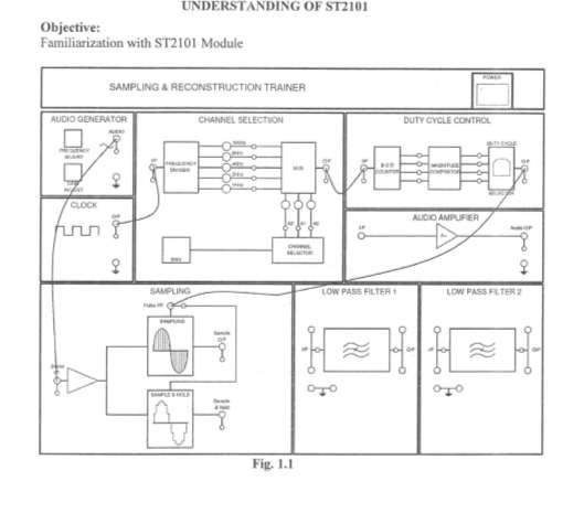
19 EXPERIMENT 1: UNDERSTANDING OF ST2101 The first Lab objective is to familiarize you with, apparatus which we will be using throughout this semester PRE LAB - QUESTIONS Answer the following Questions. Define and Explain following with formulas I. Frequency II. Clock III. Duty Cycle IV. Gain
20 V. Effect of increasing Gain on a signal VI. What is filter? VII. What is low pass filter? VIII. What is high pass filter? IX. What is by pass filter? X. What is the function of duty cycle controller?
21 LAB OBSERVATION SHEET Trainer ST2101 What is the maximum and minimum frequency that can be generated from the Audio Frequency? What function does Frequency Adjustment and gain knob do? What does channel selector do? Write down the status of LED A2 A1 and A0 when following Frequency is selected A2 A1 A0 Frequency What is the frequency of the clock generator?
22 BONUS Question Can you design a circuit which can perform the same function as Channel Selector?
23 EXPERIMENT NO 02
24
25 EXPERIMENT 2: STUDY OF SIGNAL AND SAMPLING PRE LAB - QUESTIONS Answer the following Questions. Define and Explain following with formulas I. Define Nyquist Theorem II. Define aliasing
26 III. Sketch a signal in matlab and sample it a frequency as following a. Sampling frequency < Signal frequency b. Sampling frequency = Signal frequency c. Sampling frequency > twice of signal frequency Reconstruct the signal and discuss the results: Cut and Paste your results below : Every diagram should contain the name of the student in diagram label LAB OBSERVATION SHEET Draw and Label a schematic diagram of circuit with which you have performed the experiment
27 Fill out the following table Signal Audio Generator MAX Freq Audio Generator Min Freq Audio Generator Minimum Amplitude Frequency of Clock Amplitude of clock Result of OP signal when Sampled with 2 Khz Frequency Amplitude Result of OP signal when Sampled with 4 Khz Frequency Amplitude Result of OP signal when Sampled with 8 Khz Frequency Amplitude Result of OP signal when Sampled with 16 Khz Frequency Amplitude Value Does the received signal have double polarity or single polarity What output is given if OP signal is feeded to Low pass filter 1 What is the function of duty cycle module here.
28 EXPERIMENT NO 03
29
30 PULSE MODULATION
31
32
33
34
35
36
37
38
39 EXPERIMENT NO 04
40 EXPERIMENT 4: PAM USING NATURAL AND FLAT TOP SAMPLING PRE LAB - QUESTIONS Answer the following Questions. Define and Explain following with formulas I. Define PAM II. Discuss advantages and disadvantages of PAM using natural and flat top sampling
41 LAB OBSERVATION SHEET Draw and Label a schematic diagram of circuit with which you have performed the experiment What are the rate of different Pulse signals available on trainer What is the maximum Frequency that can be generated via frequency generator on Trainer
42 What is the maximum output that is given by DC Supply What are the three type of Pulse amplitude modulation techniques available on trainer Using the same experiment, sketch the output received via flat and natural PAM options on trainer. Don t forget to mention input parameters and output parameters of signal like frequency amplitude of input and output signal Which Signal has highest frequencies? Pulse signals or Signal produced via frequency generator? Looking at the frequencies of both signal which should be message signal and which of the signal can be defined as carrier signal
43 EXPERIMENT NO 05
44 EXPERIMENT 5: STUDY PAM USING HOLD AND SAMPLING PRE LAB - QUESTIONS Answer the following Questions. Define and Explain following with formulas I. Differentiate between sampling and hold sampling II. What is the effect on energy parameter of signal if Hold sampling method is used
45 III. What is the advantage of using Hold sampling LAB OBSERVATION SHEET Draw and Label a schematic diagram of circuit with which you have performed the experiment
46 If pulse signal shows the carrier signal and the message signal is displayed by the sinusoidal signal, than what is the result of following modulation Carrier Signal Message Signal Modulated Signal Frequency Amplitude Frequency Amplitude Frequency Amplitude Using the above table write your observations regarding message and Carrier and modulated signal
47 EXPRERIMENT NO 06
48 EXPERIMENT 6: PAM MODULATION AND DEMODULATION PRE LAB - QUESTIONS Answer the following Questions. Define and Explain following with formulas I. Draw a circuit which can detect the envelop of AM signal II. What is the function of audio amplifier? III. What type of low pass filter is being used in trainer? (Answer is available in manual )
49 LAB OBSERVATION SHEET If pulse signal shows the carrier signal and the message signal is displayed by the sinusoidal signal, than what is the result of following modulation. Carrier Signal Message Signal Modulated Signal Demodulated Signal Frequency Amplitude Frequency Amplitude Frequency Amplitude Frequency Amplitude What is the effect of increasing decreasing the amplitude of message signal on Modulated wave and output signal
50 Draw the block diagram of this experiment and draw signals at every node. Done for get to mention the parameters of signal (Kindly use pencil)
51 EXPERIMENT NO 07
52 EXPERIMENT NO 08
53 EXPERIMENT 8 : STUDY PPM USING SINE WAVE INPUT A very good interactive tutorial is also available on website PRE LAB - QUESTIONS Answer the following Questions. Define and Explain following with formulas I. Define PPM II. Write some advantages and disadvantages of PPM
54 LAB OBSERVATION SHEET If pulse signal shows the carrier signal and the message signal is displayed by the sinusoidal signal, than what is the result of following modulation. Message Signal Modulated Signal Frequency Amplitude Frequency Amplitude Draw the block diagram of experiment and sketch the wave form of any of the above Experiment. Which Trainer component/block should be used if we need to demodulate the signal?
55 EXPERIMENT NO 09
56 EXPERIMENT NO 10
57 EXPERIMENT NO 11
58 EXPERIMENT 11: THE FUN PART THE PAM WAY 1. Have you ever seen your voice on oscilloscope? 2. Have you ever heard your modulated voice? 3. Have you heard your voice after demodulation? Connect a audio mic to Trainer and see if you can hear your voice via Speaker Can you see your voice wave form on oscilloscope?
59 Can you sketch it Modulate your voice signal and listen to it (Use any flat top or natural PAM). Also fill the following table Demodulate the signal and listen to your voice again. Can you hear your original voice?
60 EXPERIMENT NO 12
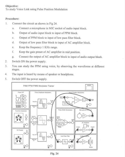
61 EXPERIMENT 12: THE FUN PART THE PPM WAY 1. Have you ever seen your voice on oscilloscope? 2. Have you ever heard your modulated voice? 3. Have you heard your voice after demodulation? Connect a audio mic to Trainer and see if you can hear your voice via Speaker Can you see your voice wave form on oscilloscope?
62 Can you sketch it Demodulate the signal and listen to your voice again. Can you hear your original voice?
63 MATLAB EXCERCISES
64 EXPERIMENT 13 # NYQUIST THEOREM I. Sketch a signal in matlab and sample it a frequency as following a. Sampling frequency < Signal frequency b. Sampling frequency = Signal frequency c. Sampling frequency > twice of signal frequency Reconstruct the signal and discuss the results: Cut and Paste your results below : Every diagram should contain the name of the student in diagram label

65 EXPERIMENT 14 # Modulation Index and Amplitude Modulation AM modulation index basics Modulation indices are described for various forms of modulation. The amplitude modulation, AM, modulation index can be defined as the measure of extent of amplitude variation about an unmodulated carrier. As with other modulation indices, the modulation index for amplitude modulation, AM, indicates the amount by which the modulated carrier varies around its static un-modulated level. When expressed as a percentage it is the same as the depth of modulation. In other words it can be expressed as: M = (RMS value of modulating signal) / (RMS value of unmodulated signal ) From this it can be seen that for an AM modulation index of 0.5, the modulation causes the signal to increase by a factor of 0.5 and decrease to 0.5 of its original level. Modulation index / modulation depth examples Typically the modulation index of a signal will vary as the modulating signal intensity varies. However some static values enable the various levels to visualised more easily. Amplitude modulated index of 0.5 When the modulation index reaches 1.0, i.e. a modulation depth of 100%, the carrier level falls to zero and rise to twice its non-modulated level.


66 Amplitude modulated index of 1.0 Any increase of the modulation index above 1.0, i.e. 100% modulation depth causes over-modulation. The carrier experiences 180 phase reversals where the carrier level would try to go below the zero point. These phase reversals give rise to additional sidebands resulting from the phase reversals (phase modulation) that extend out, in theory to infinity. This can cause serious interference to other users if not filtered. Amplitude modulated index of more than 1.0 i.e. over-modulated Broadcast stations in particular take measures to ensure that the carries of their transmissions never become over modulated. The transmitters incorporate limiters to prevent more than 100% modulation. Hover they also normally incorporate automatic audio gain controls to keep the audio levels such that near 100% modulation levels are achieved for most of the time PRE LAB - QUESTIONS What is Amplitude Modulation?
67 What are the Characteristics of Message signal and Carrier Signal Represent Amplitude Modulation via Mathematical Expressions What is modulation index, and what is its effect on Modulation for different values LAB - QUESTIONS For the following Amplitude Modulation Code, draw the signal wave forms clc; clear all; close all; t=0:0.001:1; set(0,'defaultlinelinewidth',2); A=5;%Amplitude of signal fm=input('message frequency=');%accepting input value fc=input('carrier frequency=');%accepting input value (f2>f1) mi=input('modulation Index=');%Modulation Index Sm=A*sin(2*pi*fm*t);%Message Signal subplot(3,1,1);%plotting frame divided in to 3 rows and this fig appear at 1st plot(t,sm); xlabel('time'); ylabel('amplitude'); title('message Signal'); grid on; Sc=A*sin(2*pi*fc*t);%Carrier Signal subplot(3,1,2); plot(t,sc); xlabel('time'); ylabel('amplitude');
68 title('carrier Signal'); grid on; Sfm=(A+mi*Sm).*sin(2*pi*fc*t);%AM Signal, Amplitude of Carrier changes to (A+Message) subplot(3,1,3); plot(t,sfm); xlabel('time'); ylabel('amplitude'); title('am Signal'); grid on; Paste the result of AM signal, while keeping Frequency same for all cases, and taking different values of modulation index On the basis of result, answer the following question a)the most efficient modulation is carried out when m=? b)comment about modulation when m =0, 50, -50
Department of Electronics & Communication Engineering LAB MANUAL
 Department of Electronics & Communication Engineering LAB MANUAL SUBJECT: DIGITAL COMMUNICATION [06BEC201] B.Tech III Year VI Semester (Branch: ECE) BHAGWANT UNIVERSITY SIKAR ROAD, AJMER DIGITAL COMMUNICATION
LAB 4 GENERATION OF ASK MODULATION SIGNAL
 Total Marks: / LAB 4 GENERATION OF ASK MODULATION SIGNAL Student Name:... Metrics Num:... Date:... Instructor Name:... Faculty of Engineering Technology (BTECH), Universiti Malaysia Perlis SUBMITTED Signature
Communication Systems Lab
 LAB MANUAL Communication Systems Lab (EE-226-F) Prepared by: Varun Sharma (Lab In-charge) Dayal C. Sati (Faculty In-charge) B R C M CET BAHAL DEPARTMENT OF ELECTRONICS & COMMUNICATION ENGINEERING Page
Chapter 3. Amplitude Modulation Fundamentals
 Chapter 3 Amplitude Modulation Fundamentals Topics Covered 3-1: AM Concepts 3-2: Modulation Index and Percentage of Modulation 3-3: Sidebands and the Frequency Domain 3-4: AM Power 3-5: Single-Sideband
YEDITEPE UNIVERSITY ENGINEERING FACULTY COMMUNICATION SYSTEMS LABORATORY EE 354 COMMUNICATION SYSTEMS
 YEDITEPE UNIVERSITY ENGINEERING FACULTY COMMUNICATION SYSTEMS LABORATORY EE 354 COMMUNICATION SYSTEMS EXPERIMENT 3: SAMPLING & TIME DIVISION MULTIPLEX (TDM) Objective: Experimental verification of the
Code No: R Set No. 1
 Code No: R05220405 Set No. 1 II B.Tech II Semester Regular Examinations, Apr/May 2007 ANALOG COMMUNICATIONS ( Common to Electronics & Communication Engineering and Electronics & Telematics) Time: 3 hours
Part I - Amplitude Modulation
 EE/CME 392 Laboratory 1-1 Part I - Amplitude Modulation Safety: In this lab, voltages are less than 15 volts and this is not normally dangerous to humans. However, you should assemble or modify a circuit
EE-4022 Experiment 2 Amplitude Modulation (AM)
") EE-4022 MILWAUKEE SCHOOL OF ENGINEERING 2015 Page 2-1 Student objectives: EE-4022 Experiment 2 Amplitude Modulation (AM) In this experiment the student will use laboratory modules to implement operations
EE-4022 MILWAUKEE SCHOOL OF ENGINEERING 2015 Page 2-1 Student objectives: EE-4022 Experiment 2 Amplitude Modulation (AM) In this experiment the student will use laboratory modules to implement operations
EXPERIMENT WISE VIVA QUESTIONS
 EXPERIMENT WISE VIVA QUESTIONS Pulse Code Modulation: 1. Draw the block diagram of basic digital communication system. How it is different from analog communication system. 2. What are the advantages of
cosω t Y AD 532 Analog Multiplier Board EE18.xx Fig. 1 Amplitude modulation of a sine wave message signal
 University of Saskatchewan EE 9 Electrical Engineering Laboratory III Amplitude and Frequency Modulation Objectives: To observe the time domain waveforms and spectra of amplitude modulated (AM) waveforms
Exercise 1: Frequency and Phase Modulation
 Exercise 1: Frequency and Phase Modulation EXERCISE OBJECTIVE When you have completed this exercise, you will be able to describe frequency modulation and an FM circuit. You will also be able to describe
B.Tech II Year II Semester (R13) Supplementary Examinations May/June 2017 ANALOG COMMUNICATION SYSTEMS (Electronics and Communication Engineering)
 Supplementary Examinations May/June 2017 ANALOG COMMUNICATION SYSTEMS (Electronics and Communication Engineering)") Code: 13A04404 R13 B.Tech II Year II Semester (R13) Supplementary Examinations May/June 2017 ANALOG COMMUNICATION SYSTEMS (Electronics and Communication Engineering) Time: 3 hours Max. Marks: 70 PART A
Code: 13A04404 R13 B.Tech II Year II Semester (R13) Supplementary Examinations May/June 2017 ANALOG COMMUNICATION SYSTEMS (Electronics and Communication Engineering) Time: 3 hours Max. Marks: 70 PART A
Amplitude Modulation. Ahmad Bilal
 Amplitude Modulation Ahmad Bilal 5-2 ANALOG AND DIGITAL Analog-to-analog conversion is the representation of analog information by an analog signal. Topics discussed in this section: Amplitude Modulation
Downloaded from 1
 VII SEMESTER FINAL EXAMINATION-2004 Attempt ALL questions. Q. [1] How does Digital communication System differ from Analog systems? Draw functional block diagram of DCS and explain the significance of
Pulse-Width Modulation (PWM)
") Pulse-Width Modulation (PWM) Modules: Integrate & Dump, Digital Utilities, Wideband True RMS Meter, Tuneable LPF, Audio Oscillator, Multiplier, Utilities, Noise Generator, Speech, Headphones. 0 Pre-Laboratory
Pulse-Width Modulation (PWM) Modules: Integrate & Dump, Digital Utilities, Wideband True RMS Meter, Tuneable LPF, Audio Oscillator, Multiplier, Utilities, Noise Generator, Speech, Headphones. 0 Pre-Laboratory
Title: Pulse Amplitude Modulation.
 Title: Pulse Amplitude Modulation. AIM Write a program to take input Frequency of Message Signal and find out the Aliased and Anti-Aliased wave, and also the Carrier Signal, Message Signal and their Fourier
BAPATLA ENGINEERING COLLEGE DIGITAL COMMUNICATIONS LAB EC-451. PREPARED BY S. Pallaviram, Lecturer
 BAPATLA ENGINEERING COLLEGE DIGITAL COMMUNICATIONS LAB EC-451 PREPARED BY S. Pallaviram, Lecturer Department of Electronics and Communications Engineering Bapatla Engineering College (Affiliated to Acharya
EE390 Final Exam Fall Term 2002 Friday, December 13, 2002
 Name Page 1 of 11 EE390 Final Exam Fall Term 2002 Friday, December 13, 2002 Notes 1. This is a 2 hour exam, starting at 9:00 am and ending at 11:00 am. The exam is worth a total of 50 marks, broken down
Fill in the following worksheet-style pages. A colored pen or pencil works best. The procedure is:
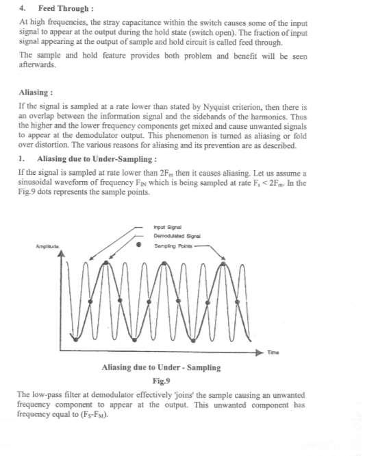
 14: ALIASING I. PRELAB FOR ALIASING LAB You might expect that to record a frequency of 4000 Hz you would have to sample at a rate of at least 4000 Hz. It turns out, however, that you actually have to sample
S.E. (Electronics/Electronics and Telecommunication Engg.) (Second Semester) EXAMINATION, 2014 COMMUNICATION THEORY (2008 PATTERN)
 (Second Semester) EXAMINATION, 2014 COMMUNICATION THEORY (2008 PATTERN)") Total No. of Questions 12] [Total No. of Printed Pages 7 Seat No. [4657]-49 S.E. (Electronics/Electronics and Telecommunication Engg.) (Second Semester) EXAMINATION, 2014 COMMUNICATION THEORY (2008 PATTERN)
Total No. of Questions 12] [Total No. of Printed Pages 7 Seat No. [4657]-49 S.E. (Electronics/Electronics and Telecommunication Engg.) (Second Semester) EXAMINATION, 2014 COMMUNICATION THEORY (2008 PATTERN)
ELG3175: Introduction to Communication Systems. Laboratory II: Amplitude Modulation
 Introduction: ELG3175: Introduction to Communication Systems Laboratory II: Amplitude Modulation In this lab, we shall investigate some fundamental aspects of the conventional AM and DSB-SC modulation
UNIT TEST I Digital Communication
 Time: 1 Hour Class: T.E. I & II Max. Marks: 30 Q.1) (a) A compact disc (CD) records audio signals digitally by using PCM. Assume the audio signal B.W. to be 15 khz. (I) Find Nyquist rate. (II) If the Nyquist
Department of Electronics & Telecommunication Engg. LAB MANUAL. B.Tech V Semester [ ] (Branch: ETE)
![Department of Electronics & Telecommunication Engg. LAB MANUAL. B.Tech V Semester [ ] (Branch: ETE)](/thumbs/86/93078052.jpg "Department of Electronics & Telecommunication Engg. LAB MANUAL. B.Tech V Semester [ ] (Branch: ETE)") Department of Electronics & Telecommunication Engg. LAB MANUAL SUBJECT:-DIGITAL COMMUNICATION SYSTEM [BTEC-501] B.Tech V Semester [2013-14] (Branch: ETE) KCT COLLEGE OF ENGG & TECH., FATEHGARH PUNJAB TECHNICAL
Department of Electronics & Telecommunication Engg. LAB MANUAL SUBJECT:-DIGITAL COMMUNICATION SYSTEM [BTEC-501] B.Tech V Semester [2013-14] (Branch: ETE) KCT COLLEGE OF ENGG & TECH., FATEHGARH PUNJAB TECHNICAL
AC LAB ECE-D ecestudy.wordpress.com
 PART B EXPERIMENT NO: 1 AIM: PULSE AMPLITUDE MODULATION (PAM) & DEMODULATION DATE: To study Pulse Amplitude modulation and demodulation process with relevant waveforms. APPARATUS: 1. Pulse amplitude modulation
Experiment No. 2 Pre-Lab Signal Mixing and Amplitude Modulation
 Experiment No. 2 Pre-Lab Signal Mixing and Amplitude Modulation Read the information presented in this pre-lab and answer the questions given. Submit the answers to your lab instructor before the experimental
DIGITAL COMMUNICATION
 DIGITAL COMMUNICATION TRAINING LAB Digital communication has emerged to augment or replace the conventional analog systems, which had been used widely a few decades back. Digital communication has demonstrated
EE 210: CIRCUITS AND DEVICES
 EE 210: CIRCUITS AND DEVICES LAB #3: VOLTAGE AND CURRENT MEASUREMENTS This lab features a tutorial on the instrumentation that you will be using throughout the semester. More specifically, you will see
Workspace for '6-pulse' Page 1 (row 1, column 1)
") Workspace for '6-pulse' Page 1 (row 1, column 1) Workspace for '6-pulse' Page 2 (row 2, column 1) Workspace for '6-pulse' Page 3 (row 3, column 1) ECEN 449 Microprocessor System Design Pulse Modulation
Workspace for '6-pulse' Page 1 (row 1, column 1) Workspace for '6-pulse' Page 2 (row 2, column 1) Workspace for '6-pulse' Page 3 (row 3, column 1) ECEN 449 Microprocessor System Design Pulse Modulation
DEPARTMENT OF E.C.E.
 PVP SIDDHARTHA INSTITUTE OF TECHNOLOGY, KANURU, VIJAYAWADA-7 DEPARTMENT OF E.C.E. ANALOG COMMUNICATIONS LAB MANUAL Department of Electronics & Communication engineering Prasad V.Potluri Siddhartha Institute
Week 8 AM Modulation and the AM Receiver
 Week 8 AM Modulation and the AM Receiver The concept of modulation and radio transmission is introduced. An AM receiver is studied and the constructed on the prototyping board. The operation of the AM
Notes on Experiment #1
 Notes on Experiment #1 Bring graph paper (cm cm is best) From this week on, be sure to print a copy of each experiment and bring it with you to lab. There will not be any experiment copies available in
Set-up. Equipment required: Your issued Laptop MATLAB ( if you don t already have it on your laptop)
") All signals found in nature are analog they re smooth and continuously varying, from the sound of an orchestra to the acceleration of your car to the clouds moving through the sky. An excerpt from http://www.netguru.net/ntc/ntcc5.htm
All signals found in nature are analog they re smooth and continuously varying, from the sound of an orchestra to the acceleration of your car to the clouds moving through the sky. An excerpt from http://www.netguru.net/ntc/ntcc5.htm
 UNIT III -- DATA AND PULSE COMMUNICATION PART-A 1. State the sampling theorem for band-limited signals of finite energy. If a finite energy signal g(t) contains no frequency higher than W Hz, it is completely
Florida Atlantic University Biomedical Signal Processing Lab Experiment 2 Signal Transduction: Building an analog Electrocardiogram (ECG)
") Florida Atlantic University Biomedical Signal Processing Lab Experiment 2 Signal Transduction: Building an analog Electrocardiogram (ECG) 1. Introduction: The Electrocardiogram (ECG) is a technique of
Florida Atlantic University Biomedical Signal Processing Lab Experiment 2 Signal Transduction: Building an analog Electrocardiogram (ECG) 1. Introduction: The Electrocardiogram (ECG) is a technique of
Figure 1: Block diagram of Digital signal processing
 Experiment 3. Digital Process of Continuous Time Signal. Introduction Discrete time signal processing algorithms are being used to process naturally occurring analog signals (like speech, music and images).
AMPLITUDE MODULATION
 AMPLITUDE MODULATION PREPARATION...2 theory...3 depth of modulation...4 measurement of m... 5 spectrum... 5 other message shapes.... 5 other generation methods...6 EXPERIMENT...7 aligning the model...7
CHAPTER 2! AMPLITUDE MODULATION (AM)
") CHAPTER 2 AMPLITUDE MODULATION (AM) Topics 2-1 : AM Concepts 2-2 : Modulation Index and Percentage of Modulation 2-3 : Sidebands and the Frequency Domain 2-4 : Single-Sideband Modulation 2-5 : AM Power
CHAPTER 2 AMPLITUDE MODULATION (AM) Topics 2-1 : AM Concepts 2-2 : Modulation Index and Percentage of Modulation 2-3 : Sidebands and the Frequency Domain 2-4 : Single-Sideband Modulation 2-5 : AM Power
ECEGR Lab #8: Introduction to Simulink
 Page 1 ECEGR 317 - Lab #8: Introduction to Simulink Objective: By: Joe McMichael This lab is an introduction to Simulink. The student will become familiar with the Help menu, go through a short example,
QUESTION BANK. Sandeep Kumar Bansal. Electronics & Communication Department
 QUESTION BANK Sandeep Kumar Bansal Electronics & Communication Department ANALOG AND DIGITAL COMMUNICATION QUESTION BANK BRANCH 4 TH SEM CS/IT UNIT-1 1. Draw the circuit diagram of balanced modulator using
Group: Names: Resistor Band Colors Measured Value ( ) R 1 : 1k R 2 : 1k R 3 : 2k R 4 : 1M R 5 : 1M
 R 1 : 1k R 2 : 1k R 3 : 2k R 4 : 1M R 5 : 1M") 2.4 Laboratory Procedure / Summary Sheet Group: Names: (1) Select five separate resistors whose nominal values are listed below. Record the band colors for each resistor in the table below. Then connect
2.4 Laboratory Procedure / Summary Sheet Group: Names: (1) Select five separate resistors whose nominal values are listed below. Record the band colors for each resistor in the table below. Then connect
Amplitude Modulation Fundamentals
 3 chapter Amplitude Modulation Fundamentals In the modulation process, the baseband voice, video, or digital signal modifies another, higher-frequency signal called the carrier, which is usually a sine
OBJECTIVES EQUIPMENT LIST
 1 Reception of Amplitude Modulated Signals AM Demodulation OBJECTIVES The purpose of this experiment is to show how the amplitude-modulated signals are demodulated to obtain the original signal. Also,
Laboratory 2 (drawn from lab text by Alciatore)
") Laboratory 2 (drawn from lab text by Alciatore) Instrument Familiarization and Basic Electrical Relations Required Components: 2 1k resistors 2 1M resistors 1 2k resistor Objectives This exercise is designed
Laboratory 2 (drawn from lab text by Alciatore) Instrument Familiarization and Basic Electrical Relations Required Components: 2 1k resistors 2 1M resistors 1 2k resistor Objectives This exercise is designed
 UNIT I FUNDAMENTALS OF ANALOG COMMUNICATION Introduction In the Microbroadcasting services, a reliable radio communication system is of vital importance. The swiftly moving operations of modern communities
(b) What are the differences between FM and PM? (c) What are the differences between NBFM and WBFM? [9+4+3]
![(b) What are the differences between FM and PM? (c) What are the differences between NBFM and WBFM? [9+4+3]](/thumbs/85/91561193.jpg "(b) What are the differences between FM and PM? (c) What are the differences between NBFM and WBFM? [9+4+3]") Code No: RR220401 Set No. 1 1. (a) The antenna current of an AM Broadcast transmitter is 10A, if modulated to a depth of 50% by an audio sine wave. It increases to 12A as a result of simultaneous modulation
Code No: RR220401 Set No. 1 1. (a) The antenna current of an AM Broadcast transmitter is 10A, if modulated to a depth of 50% by an audio sine wave. It increases to 12A as a result of simultaneous modulation
R.B.V.R.R. WOMEN S COLLEGE (AUTONOMOUS) Narayanaguda, Hyderabad. ELECTRONIC PRINCIPLES AND APPLICATIONS
 Narayanaguda, Hyderabad. ELECTRONIC PRINCIPLES AND APPLICATIONS") R.B.V.R.R. WOMEN S COLLEGE (AUTONOMOUS) Narayanaguda, Hyderabad. DEPARTMENT OF PHYSICS QUESTION BANK FOR SEMESTER V PHYSICS PAPER VI (A) ELECTRONIC PRINCIPLES AND APPLICATIONS UNIT I: SEMICONDUCTOR DEVICES
R.B.V.R.R. WOMEN S COLLEGE (AUTONOMOUS) Narayanaguda, Hyderabad. DEPARTMENT OF PHYSICS QUESTION BANK FOR SEMESTER V PHYSICS PAPER VI (A) ELECTRONIC PRINCIPLES AND APPLICATIONS UNIT I: SEMICONDUCTOR DEVICES
LINEAR APPLICATIONS OF OPERATIONAL AMPLIFIERS
 LINEAR APPLICATIONS OF OPERATIONAL AMPLIFIERS OBJECTIVE The purpose of the experiment is to examine the linear applications of an operational amplifier. The applications that are designed and analyzed
REV NO EXPERIMENT NO 1 AIM: To study the PN junction diode characteristics under Forward & Reverse bias conditions. APPARATUS REQUIRED:
 KARNAL INSTITUTE OF TECHNOLOGY & MANAGEMENT KUNJPURA, KARNAL LAB MANUAL OF ------- SUBJECT CODE DATE OF ISSUE: SEMESTER: BRANCH: REV NO EXPERIMENT NO 1 AIM: To study the PN junction diode characteristics
University of Portland EE 271 Electrical Circuits Laboratory. Experiment: Op Amps
 University of Portland EE 271 Electrical Circuits Laboratory Experiment: Op Amps I. Objective The objective of this experiment is to learn how to use an op amp circuit to prevent loading and to amplify
CME 312-Lab Communication Systems Laboratory
 Objective: By the end of this experiment, the student should be able to: 1. Demonstrate the Modulation and Demodulation of the AM. 2. Observe the relation between modulation index and AM signal envelope.
TE 302 DISCRETE SIGNALS AND SYSTEMS. Chapter 1: INTRODUCTION
 TE 302 DISCRETE SIGNALS AND SYSTEMS Study on the behavior and processing of information bearing functions as they are currently used in human communication and the systems involved. Chapter 1: INTRODUCTION
Experiment 1.A. Working with Lab Equipment. ECEN 2270 Electronics Design Laboratory 1
 .A Working with Lab Equipment Electronics Design Laboratory 1 1.A.0 1.A.1 3 1.A.4 Procedures Turn in your Pre Lab before doing anything else Setup the lab waveform generator to output desired test waveforms,
CATALOG. ANALOG COMMUNICATION SYSTEMS DIGITAL COMMUNICATION SYSTEMS Microcontroller kits Arm controller kits PLC Trainer KITS Regulated Power supplies
 CATALOG ANALOG COMMUNICATION SYSTEMS DIGITAL COMMUNICATION SYSTEMS Microcontroller kits Arm controller kits PLC Trainer KITS Regulated Power supplies UNION INTRUMENTS #17 & 18, 4 th floor, Hanumathra Arcade
Description of the AM Superheterodyne Radio Receiver
 Superheterodyne AM Radio Receiver Since the inception of the AM radio, it spread widely due to its ease of use and more importantly, it low cost. The low cost of most AM radios sold in the market is due
Electronic Circuits I Laboratory 03 Rectifiers
 Electronic Circuits I Laboratory 03 Rectifiers # Student ID Student Name Grade (10) 1 Instructor signature 2 3 4 5 Delivery Date -1 / 18 - Objectives In this experiment, you will get to know a group of
COMMUNICATION SYSTEMS-II (In continuation with Part-I)
") MODULATING A SIGNAL COMMUNICATION SYSTEMS-II (In continuation with Part-I) TRANSMITTING SIGNALS : In order to transmit the original low frequency baseband message efficiently over long distances, the signal
MODULATING A SIGNAL COMMUNICATION SYSTEMS-II (In continuation with Part-I) TRANSMITTING SIGNALS : In order to transmit the original low frequency baseband message efficiently over long distances, the signal
MAHALAKSHMI ENGINEERING COLLEGE-TRICHY QUESTION BANK UNIT IV PART-A
 MAHALAKSHMI ENGINEERING COLLEGE-TRICHY QUESTION BANK SATELLITE COMMUNICATION DEPT./SEM.:ECE/VIII UNIT IV PART-A 1. What are the advantages of the super heterodyne receiver over TRF receiver? (AUC MAY 2004)
ECE159H1S University of Toronto 2014 EXPERIMENT #2 OP AMP CIRCUITS AND WAVEFORMS ECE159H1S
 ECE159H1S University of Toronto 2014 EXPERIMENT #2 OP AMP CIRCUITS AND WAVEFORMS ECE159H1S OBJECTIVES: To study the performance and limitations of basic op-amp circuits: the inverting and noninverting
World Journal of Engineering Research and Technology WJERT
 wjert, 2017, Vol. 3, Issue 2, 185-197 Original Article ISSN 2454-695X Susanchi et al. WJERT www.wjert.org SJIF Impact Factor: 4.326 DESIGN AND SIMULATION OF DOUBLE SIDE BAND SUPPRESSED CARRIER MODEL USING
Laboratory Assignment 5 Amplitude Modulation
 Laboratory Assignment 5 Amplitude Modulation PURPOSE In this assignment, you will explore the use of digital computers for the analysis, design, synthesis, and simulation of an amplitude modulation (AM)
Let us consider the following block diagram of a feedback amplifier with input voltage feedback fraction,, be positive i.e. in phase.
 P a g e 2 Contents 1) Oscillators 3 Sinusoidal Oscillators Phase Shift Oscillators 4 Wien Bridge Oscillators 4 Square Wave Generator 5 Triangular Wave Generator Using Square Wave Generator 6 Using Comparator
Sampling and Reconstruction
 Experiment 10 Sampling and Reconstruction In this experiment we shall learn how an analog signal can be sampled in the time domain and then how the same samples can be used to reconstruct the original
TE 0224 ANALOG COMMUNICATION LAB. Laboratory Manual
 TE 0224 ANALOG COMMUNICATION LAB Laboratory Manual DEPARTMENT OF TELECOMMUNICATION ENGINEERING SRM UNIVERSITY S.R.M. NAGAR, KATTANKULATHUR 603 203. FOR PRIVATE CIRCULATION ONLY ALL RIGHTS RESERVED DEPARTMENT
EE 368 Electronics Lab. Experiment 10 Operational Amplifier Applications (2)
") EE 368 Electronics Lab Experiment 10 Operational Amplifier Applications (2) 1 Experiment 10 Operational Amplifier Applications (2) Objectives To gain experience with Operational Amplifier (Op-Amp). To
EE 368 Electronics Lab Experiment 10 Operational Amplifier Applications (2) 1 Experiment 10 Operational Amplifier Applications (2) Objectives To gain experience with Operational Amplifier (Op-Amp). To
Laboratory 2. Lab 2. Instrument Familiarization and Basic Electrical Relations. Required Components: 2 1k resistors 2 1M resistors 1 2k resistor
 Laboratory 2 nstrument Familiarization and Basic Electrical Relations Required Components: 2 1k resistors 2 1M resistors 1 2k resistor 2.1 Objectives This exercise is designed to acquaint you with the
EE 421L Digital Electronics Laboratory. Laboratory Exercise #9 ADC and DAC
 EE 421L Digital Electronics Laboratory Laboratory Exercise #9 ADC and DAC Department of Electrical and Computer Engineering University of Nevada, at Las Vegas Objective: The purpose of this laboratory
Lab 6: Building a Function Generator
 ECE 212 Spring 2010 Circuit Analysis II Names: Lab 6: Building a Function Generator Objectives In this lab exercise you will build a function generator capable of generating square, triangle, and sine
Department of Communication Engineering Digital Communication Systems Lab CME 313-Lab
 German Jordanian University Department of Communication Engineering Digital Communication Systems Lab CME 313-Lab Experiment 2 Pulse Modulation Eng. AnasAlashqar Dr. Ala' Khalifeh 1 Experiment 1Experiment
University of North Carolina, Charlotte Department of Electrical and Computer Engineering ECGR 3157 EE Design II Fall 2009
 University of North Carolina, Charlotte Department of Electrical and Computer Engineering ECGR 3157 EE Design II Fall 2009 Lab 1 Power Amplifier Circuits Issued August 25, 2009 Due: September 11, 2009
ME 365 EXPERIMENT 7 SIGNAL CONDITIONING AND LOADING
 ME 365 EXPERIMENT 7 SIGNAL CONDITIONING AND LOADING Objectives: To familiarize the student with the concepts of signal conditioning. At the end of the lab, the student should be able to: Understand the
END-OF-YEAR EXAMINATIONS ELEC321 Communication Systems (D2) Tuesday, 22 November 2005, 9:20 a.m. Three hours plus 10 minutes reading time.
 Tuesday, 22 November 2005, 9:20 a.m. Three hours plus 10 minutes reading time.") END-OF-YEAR EXAMINATIONS 2005 Unit: Day and Time: Time Allowed: ELEC321 Communication Systems (D2) Tuesday, 22 November 2005, 9:20 a.m. Three hours plus 10 minutes reading time. Total Number of Questions:
END-OF-YEAR EXAMINATIONS 2005 Unit: Day and Time: Time Allowed: ELEC321 Communication Systems (D2) Tuesday, 22 November 2005, 9:20 a.m. Three hours plus 10 minutes reading time. Total Number of Questions:
EXPERIMENT 3 - Part I: DSB-SC Amplitude Modulation
 OBJECTIVE To generate DSB-SC amplitude modulated signal. EXPERIMENT 3 - Part I: DSB-SC Amplitude Modulation PRELIMINARY DISCUSSION In the modulation process, the message signal (the baseband voice, video,
RAO PAHALD SINGH GROUP OF INSTITUTIONS BALANA(MOHINDER GARH)123029
123029") 1 COMMUNICATION SYSTEM LAB (EE-226 -F) Communication System Lab (EE-226-F) LAB MANUAL IV SEMESTER RAO PAHALD SINGH GROUP OF INSTITUTIONS BALANA(MOHINDER GARH)123029 Department Of Electronics and Communication
1 COMMUNICATION SYSTEM LAB (EE-226 -F) Communication System Lab (EE-226-F) LAB MANUAL IV SEMESTER RAO PAHALD SINGH GROUP OF INSTITUTIONS BALANA(MOHINDER GARH)123029 Department Of Electronics and Communication
ANALOGUE AND DIGITAL COMMUNICATION
 ANALOGUE AND DIGITAL COMMUNICATION Syed M. Zafi S. Shah Umair M. Qureshi Lecture xxx: Analogue to Digital Conversion Topics Pulse Modulation Systems Advantages & Disadvantages Pulse Code Modulation Pulse
Topic Pulse Modulation. analyse and draw graphs to illustrate the following pulse carrier
 Learning Objectives: At the end of this topic you will be able to; analyse and draw graphs to illustrate the following pulse carrier modulation techniques: o Pulse width modulation o Pulse position modulation
INTRODUCTION TO COMMUNICATION SYSTEMS LABORATORY IV. Binary Pulse Amplitude Modulation and Pulse Code Modulation
 INTRODUCTION TO COMMUNICATION SYSTEMS Introduction: LABORATORY IV Binary Pulse Amplitude Modulation and Pulse Code Modulation In this lab we will explore some of the elementary characteristics of binary
Jawaharlal Nehru Engineering College
 Jawaharlal Nehru Engineering College Laboratory Manual COMMUNICATION ENGINEERING For Author JNEC, Aurangabad. Second Year Students Lab manual made by PROF. S.A. ANNANDATE PROF. P. B. MURMUDE PROF. P.B.YADAV
Lab 6 Prelab Grading Sheet
 Lab 6 Prelab Grading Sheet NAME: Read through the Background section of this lab and print the prelab and in-lab grading sheets. Then complete the steps below and fill in the Prelab 6 Grading Sheet. You
Dhanalakshmi College of Engineering Manimangalam, Tambaram, Chennai
 Dhanalakshmi College of Engineering Manimangalam, Tambaram, Chennai 601 301 DEPARTMENT OF ELECTRONICS AND COMMUNICATION ENGINEERING V SEMESTER - R 2013 EC6512 COMMUNICATION SYSTEMS LABORATORY LABORATORY
German Jordanian University Department of Communication Engineering Digital Communication Systems Lab. CME 313-Lab
 German Jordanian University Department of Communication Engineering Digital Communication Systems Lab CME 313-Lab Experiment 1 Sampling Theorem Eng. Anas Alashqar Dr. Ala' Khalifeh 1 Experiment 1 Objectives:
MTI 7601 PAM Modulation and Demodulation
 Page 1 of 1 MTI 7601 PAM Modulation and Demodulation Contents Aims of the Exercise Learning about the functioning principle of the pulse-amplitude modulation (sampling, time division multiplex operation)
Modulation is the process of impressing a low-frequency information signal (baseband signal) onto a higher frequency carrier signal
 onto a higher frequency carrier signal") Modulation is the process of impressing a low-frequency information signal (baseband signal) onto a higher frequency carrier signal Modulation is a process of mixing a signal with a sinusoid to produce
Modulation is the process of impressing a low-frequency information signal (baseband signal) onto a higher frequency carrier signal Modulation is a process of mixing a signal with a sinusoid to produce
Amplitude Modulated Systems
 Amplitude Modulated Systems Communication is process of establishing connection between two points for information exchange. Channel refers to medium through which message travels e.g. wires, links, or
Problem Sheet for Amplitude Modulation
 Problem heet for Amplitude Modulation Q1: For the sinusoidaly modulated DB/LC waveform shown in Fig. below. a Find the modulation index. b ketch a line spectrum. c Calculated the ratio of average power
DIGITAL COMMUNICATIONS LAB
 DIGITAL COMMUNICATIONS LAB List of Experiments: 1. PCM Generation and Detection. 2. Differential Pulse Code modulation. 3. Delta modulation. 4. Time Division Multiplexing of 2band Limited Signals. 5. Frequency
LABORATORY MANUAL COMMUNICATIONS LABORATORY EE 321
 LABORATORY MANUAL COMMUNICATIONS LABORATORY EE 321 K. Rad October 26, 2005 DEPARTMENT OF ELECTRICAL & COMPUTER ENGINEERING CALIFORNIA STATE UNIVERSITY, LOS ANGELES K. Rad Experiment 1 Part 1: Exercise
Federal Urdu University of Arts, Science & Technology Islamabad Pakistan SECOND SEMESTER ELECTRONICS - I
 SECOND SEMESTER ELECTRONICS - I BASIC ELECTRICAL & ELECTRONICS LAB DEPARTMENT OF ELECTRICAL ENGINEERING Prepared By: Checked By: Approved By: Engr. Yousaf Hameed Engr. M.Nasim Khan Dr.Noman Jafri Lecturer
DIGITAL COMMUNICATIONS
 DIGITAL COMMUNICATIONS LAB MANUAL (STUDENT COPY) DEPARTMENT OF ELECTRONICS AND COMMUNICATION ENGINEERING GUDLAVALLERU ENGINEERING COLLEGE SESHADRI RAO KNOWLEDGE VILLAGE::GUDLAVALLERU INDEX S.NO. NAME OF
Agilent 33220A Function Generator Tutorial
 Contents UNIVERSITY OF CALIFORNIA AT BERKELEY College of Engineering Department of Electrical Engineering and Computer Sciences EE105 Lab Experiments Agilent 33220A Function Generator Tutorial 1 Introduction
L A B 3 : G E N E R A T I N G S I N U S O I D S
 L A B 3 : G E N E R A T I N G S I N U S O I D S NAME: DATE OF EXPERIMENT: DATE REPORT SUBMITTED: 1/7 1 THEORY DIGITAL SIGNAL PROCESSING LABORATORY 1.1 GENERATION OF DISCRETE TIME SINUSOIDAL SIGNALS IN
Data Conversion Circuits & Modulation Techniques. Subhasish Chandra Assistant Professor Department of Physics Institute of Forensic Science, Nagpur
 Data Conversion Circuits & Modulation Techniques Subhasish Chandra Assistant Professor Department of Physics Institute of Forensic Science, Nagpur Data Conversion Circuits 2 Digital systems are being used
Section 10: Radio Frequency Communication
 Section 10: Radio Frequency Communication Section Contents This section contains the following: Introducing Radio Frequency on page 10-2 RF Amplifier with Thermal Noise Source on page 10-4. Worksheets
EECS 122: Introduction to Computer Networks Encoding and Framing. Questions
 EECS 122: Introduction to Computer Networks Encoding and Framing Computer Science Division Department of Electrical Engineering and Computer Sciences University of California, Berkeley Berkeley, CA 94720-1776
Encoding and Framing
 Encoding and Framing EECS 489 Computer Networks http://www.eecs.umich.edu/~zmao/eecs489 Z. Morley Mao Tuesday Nov 2, 2004 Acknowledgement: Some slides taken from Kurose&Ross and Katz&Stoica 1 Questions
 Modulations Analog Modulations Amplitude modulation (AM) Linear modulation Frequency modulation (FM) Phase modulation (PM) cos Angle modulation FM PM Digital Modulations ASK FSK PSK MSK MFSK QAM PAM Etc.
Experiment One: Generating Frequency Modulation (FM) Using Voltage Controlled Oscillator (VCO)
 Using Voltage Controlled Oscillator (VCO)") Experiment One: Generating Frequency Modulation (FM) Using Voltage Controlled Oscillator (VCO) Modified from original TIMS Manual experiment by Mr. Faisel Tubbal. Objectives 1) Learn about VCO and how
Experiment One: Generating Frequency Modulation (FM) Using Voltage Controlled Oscillator (VCO) Modified from original TIMS Manual experiment by Mr. Faisel Tubbal. Objectives 1) Learn about VCO and how
DHANALAKSHMI SRINIVASAN COLLEGE OF ENGINEERING AND TECHNOLOGY CS6304- ANALOG AND DIGITAL COMMUNICATION BE-CSE/IT SEMESTER III REGULATION 2013 Faculty
 DHANALAKSHMI SRINIVASAN COLLEGE OF ENGINEERING AND TECHNOLOGY CS6304- ANALOG AND DIGITAL COMMUNICATION BE-CSE/IT SEMESTER III REGULATION 2013 Faculty Name: S.Kalpana, AP/ECE QUESTION BANK UNIT I ANALOG
EXPERIMENT 4 - Part I: DSB Amplitude Modulation
 OBJECTIVE To generate DSB amplitude modulated signal. EXPERIMENT 4 - Part I: DSB Amplitude Modulation PRELIMINARY DISCUSSION In an amplitude modulation (AM) communications system, the message signal is
Lab 12 Laboratory 12 Data Acquisition Required Special Equipment: 12.1 Objectives 12.2 Introduction 12.3 A/D basics
 Laboratory 12 Data Acquisition Required Special Equipment: Computer with LabView Software National Instruments USB 6009 Data Acquisition Card 12.1 Objectives This lab demonstrates the basic principals
Understanding Digital Communication Principles.
 s Understanding Digital Communication Principles Scientech TechBooks are compact and user friendly learning platforms to provide a modern, portable, comprehensive and practical way to learn Technology.