Digital Communication Digital Modulation Schemes
|
|
|
- Louise Ryan
- 6 years ago
- Views:
Transcription
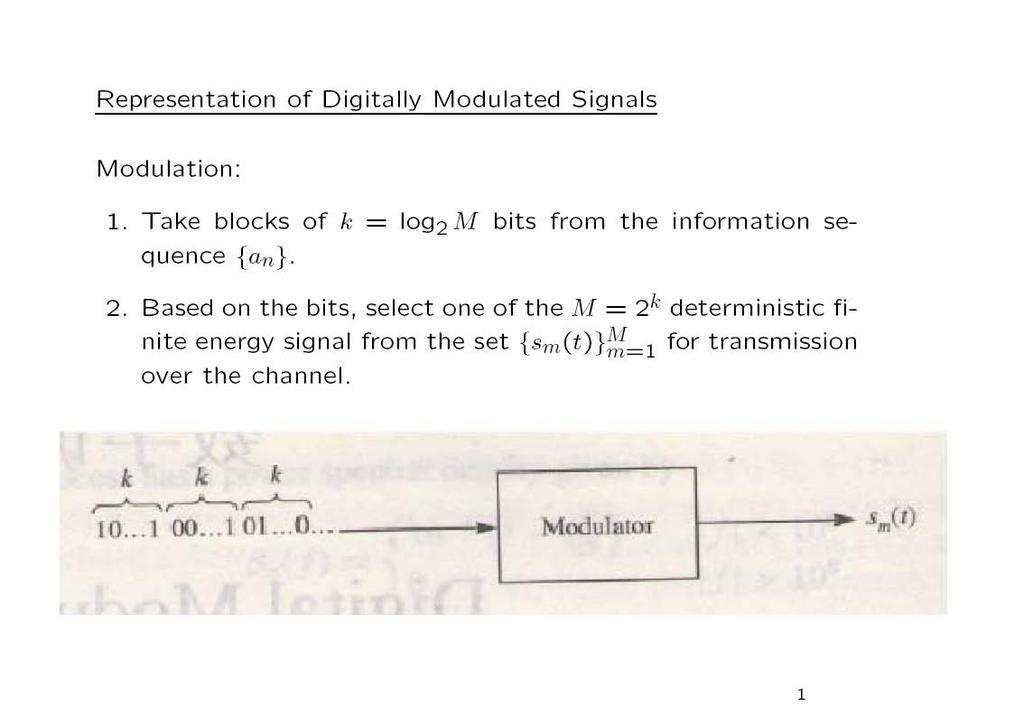
1 Digital Communication Digital Modulation Schemes Yabo Li Fall, 2013
2 Chapter Outline Representation of Digitally Modulated Signals Linear Modulation PAM PSK QAM Multi-Dimensional Signal Non-linear Modulation CPM Spectrum of the Digitally Modulated Signals 1
3
4 Important Parameters in Digital Modulation Symbol Duration/Interval: The time T s in seconds that is used to transmit the signal waveform s m (t). Bit Duration/Interval: The time T b in seconds that is used to transmit one bit: Symbol Rate: T b = T s k. R s = 1 T s symbols/sec. Bit Rate: R = kr s = R s log 2 M bits/sec. 2
5 Important Parameters in Digital Modulation Average Signal Energy: E avg = M m=1 p m E m, E m is the energy of s m (t), p m is the probability of the m-th signal. p m = M 1 for equal probable signals. Average Bit Energy: E bavg = E avg k = E avg log 2 M, Average Power: P avg = E bavg T b = E avg T s. 3
6 Memoryless Modulation vs. Modulation with Memory Memoryless means the mapping from {a n } to {s m (t)} doesn t depend on previously transmitted waveform. Modulation with memory is vice versa. Linear Modulation vs. Non-linear Modulation Linear means the principal of superposition applies in the mapping from {a n } to {s m (t)}. Linear Non-Linear Memoryless PAM, PSK, QAM? Memory DPSK CPM, MSK, CPFSK 4
7
8 PAM: The Signal Space Representation In signal space, the PAM modulated signal has only 1 dimension. s m (t) = s m f(t) f(t) = 2Eg g(t)cos2πf ct s m = A m E g 2 where E g = T 0 g 2 (t)dt The Euclidean distance between any pair of signal points is: d mn = s m s n 2 Eg = A m A n 2 The minimum distance between the signal points is: d min = 2E g 6
9
10 PSK (Phase Shift Keying) The Transmit Waveform is: s m (t) = R [ e j2π(m 1) M = g(t)cos ] g(t)e j2πf ct 2π(m 1) M Signal Space Representation: cos2πf c t g(t)sin s m (t) = s mi f 1 (t) + s mq f 2 (t) f 1 (t) = 2Eg g(t)cos2πf ct 2π(m 1) M sin2πf c t f 2 (t) = 2Eg g(t)sin2πf ct s m [s mi s mq ] = Eg 2 cos 2π(m 1) M Eg 2 2π(m 1) sin M 8
11
12 QAM (Quadrature Amplitude Modulation) The transmit waveform: s m (t) = R { (A mi + A mq )g(t)e j2πf ct } = A mi g(t)cos2πf c t A mq g(t)sin2πf c t Signal Space Representation: s m = [s mi s mq ] = A mi Eg 2 A mq Eg 2 The distance between two points d mn = s m s n = Eg 2 [ (Ami A ni ) 2 + (A mq A nq ) 2] 10
13 QAM (Quadrature Amplitude Modulation) The minimum distance: Assume A mi and A mq take the set of discrete values {(2m 1 M), m = 1,2,, M}, then d min = 2E g The average energy of the points E avg = 1 M E g 2 M m=1 (A 2 mi + A2 mq ) The d min, E avg and the kissing number determine the performance of the modulation scheme in the AWGN channel. 11
14
15 Multi-dimensional Signal Modulation is the procedure that maps the information bits to the waveforms that to be transmitted to the channel. For PAM, PSK or QAM, the bits are mapped to a real or complex scalar value. For multi-dimensional signal, the bits can be mapped to a real or complex vector. Practical multi-dimensional modulations include time domain multi-dimensional signals, frequency domain multidimensional signals and code domain multi-dimensional signals, etc. 13
16 Multi-dimensional Signal Orthogonal Signaling The M transmitted signals are orthogonal, i.e., { E m = n < s m (t), s n (t) >= 1 m, n M 0 m n < s m (t), s n (t) > means the inner product between s m (t) and s n (t). The orthonormal basis in the signal space is: f i (t) = s j(t) E, 1 j N. Obviously, for orthogonal signaling, the dimension N is equal to the number of signals M, i.e., N = M In signal space, the signal vector can be represented as: s 1 = ( E,0,0,,0) s 2 = (0, E,0,,0). =. s M = (0,0,,0, E) 14
17 Multi-dimensional Signal Orthogonal Signaling The signal pairs have equal distance and the distance is equal to the minimal distance, i.e., d mn = d min = 2E Practical Orthogonal Signaling Schemes Frequency Domain Orthogonal Signaling: FSK (Frequency Shift Keying), OFDM (Orthogonal Frequency Division Multiplexing) Time Domain Orthogonal Signaling: TDM (Time Division Multiplexing) Code Domain Orthogonal Signaling: CDM (Code Division Multiplexing) 15
18 Multi-dimensional Signal Biorthogonal Signaling M biorthogonal signals are constructed from M 2 orthogonal signals by including the negative of the orthogonal signals. The dimension is equal to half of the number of signals, i.e., N = M 2. The correlation factor between any pair is: ρ s m s n s m s n = 0 or 1, m n. The minimum distance is: d min = 2E. 16
19 Multi-dimensional Signal Simplex Signaling Assume the M orthogonal signals in vector representation is s m, m = 1,2,, M, their mean is: s = 1 M The simplex signal is defined as: M s m m=1 s m = s m s, m = 1,2,, M The dimension of the simplex signal is: N = M 1 The energy per waveform is: s m 2 = s m s 2 = E ( 1 1 ) M The minimum distance is d min = 2E. 17
20
21
22 Non-Linear Modulation with Memory: CPM The TX waveform is: s(t) = 2ε T cos(2πf ct + φ(t; I) + φ 0 ) φ 0 : Initial phase of the carrier φ(t; I): Time varying phase of the carrier φ(t; I) = 2π n k= I k h k q(t kt), nt t (n + 1)T I k {±1, ±3,, ±(M 1)} is the sequence of the information symbols. h k : modulation index, gives the step size of the change of the phase. q(t): normalized waveform shape, defines the shape of the change of the phase. 20
23 Modulation Index Define the step of the change of the phase between continuous symbols. h k = h, then the modulation index is fixed for all symbols Multi-h CPM: h k changes with k. Full Response and Partial Response q(t) define the shape of the change of the phase. q(t) = t 0 g(τ)dτ { g(t) = 0, for t > T, full response g(t) 0, for t > T, partial response 21
24
25 CPFSK (Continuous Frequency Shift Keying) A special case of CPM: φ(t; I) = 2π n k= I k h k q(t kt), nt t (n + 1)T Modulation Index is: h k = h = 2f d T Phase Change Shape is: q(t) = 0 t 0 t 2π 0 t T 1 2 t T Substitute h and q(t) into φ(t; I), we can get: φ(t; I) = 2πf d T n 1 k= = θ n + 2πhI n q(t nt) I k + 2πf d q(t nt)i n 23
26
27 MSK (Minimum Shift Keying) A special case of CPFSK at h = 1/2 When h = 1 2, f d = 1 4T, f = 2f d = 1 2T It is the minimum frequency separation that ensures the orthogonality of the two signals in a interval of T. GMSK (Gaussian Minimum Shift Keying) h = 1/2 with Gaussian pulse shape { [ ( g(t) = Q 2πB t T ) / ] ln2 Q 2 Q(t) is the Gaussian tail function. GMSK is used in the GSM system. [ 2πB ( t + T ) / ]} ln2 2 25
28 Spectrum Characteristics of the Digitally Modulated Signals The band-pass signal s(t) can be represented as s(t) = R { s l (t)e j2πf ct } s l (t): Equivalent low-pass signal. The auto-correlation of s(t) is: φ ss (τ) = R{φ sl s l (τ)e j2πf ct } The Fourier transform of φ ss (τ) can be written as: Φ ss (f) = 1 [ Φsl s 2 l (f f c ) + Φ sl s l ( f f c ) ] Φ sl s l (f) is the PSD of the low-pass equivalent signal s l (t). So in order to calculate Φ ss (f), it is sufficient to calculate Φ sl s l (f). 26
29 Spectrum for Linearly Modulated Signals For linear modulated signals, s l (t) can be written as: s l (t) = + n= I n g(t nt) I n : the sequence of symbols results from the mapping of k bits. I n is real for PAM and complex for PSK and QAM. g(t) the pulse shape. The auto-correlation of s l (t) is: φ sl s l (t + τ; t) = E [ s l (t)s l(t + τ) ] = + + n= m= E [ I n I m] g (t nt)g(t + τ mt) 27
30 Spectrum for Linearly Modulated Signals Assume {I n } is wide-sense stationary with mean µ i and auto-correlation φ ii (m) = E [ I n I n+m ] Then φ sl s l (t + τ; t) can be written as: φ sl s l (t + τ; t) = = + n= + m= φ ii (m n)g (t nt)g(t + τ mt) φ ii (m) + n= g (t nt)g(t + τ nt mt) + n= g (t nt)g(t + τ nt mt) is cyclostationary with period T, so is φ sl s l (t + τ; t). 28
31 Spectrum for Linearly Modulated Signals Average φ sl s l (t + τ; t) over a single period φ sl s l (τ) = 1 T = T/2 T/2 φ s l s l (t + τ; t)dt + m= φ ii (m) + n= 1 T T/2 nt T/2 nt g (t)g(t + τ mt)dt Define φ gg (τ) = + g (t)g(t + τ)dt φ sl s l (τ) can be written as: It a convolution! φ sl s l (τ) = 1 T + m= φ ii (m)φ gg (τ mt) 29
32 Spectrum for Linearly Modulated Signals F{φ gg (τ)} = G(f) 2, G(f) = F{g(t)} F{φ ii (m)} Φ ii (f) = + m= φ ii (m)e j2πfmt Φ sl s l (f) = 1 T G(f) 2 Φ ii (f) Consider the case that the information symbols are real and mutually uncorrelated, then φ ii (m) can be written as: φ ii (m) = { σ 2 i + µ 2 i (m = 0) µ 2 i (m 0) Then Φ ii (f) is: Φ i i(f) = σ 2 i +µ2 i + m= e j2πfmt = σ 2 i +µ2 i T + m= δ ( f m T ) 30
33 Spectrum for Linearly Modulated Signals The spectrum Φ sl s l (f) is: Φ sl s l (f) = σ2 i T G(f) 2 + µ2 i T 2 + m= G ( m T ) 2 δ ( f m T ) The first term is continuous spectrum controlled by the pulse g(t). The second term is discrete spectrum with separation 1/T If µ i = 0, then the second term vanishes. So, it is desired to have zero mean information sequence. 31
Mobile Radio Systems OPAM: Understanding OFDM and Spread Spectrum
 Mobile Radio Systems OPAM: Understanding OFDM and Spread Spectrum Klaus Witrisal witrisal@tugraz.at Signal Processing and Speech Communication Laboratory www.spsc.tugraz.at Graz University of Technology
Lecture #11 Overview. Vector representation of signal waveforms. Two-dimensional signal waveforms. 1 ENGN3226: Digital Communications L#
 Lecture #11 Overview Vector representation of signal waveforms Two-dimensional signal waveforms 1 ENGN3226: Digital Communications L#11 00101011 Geometric Representation of Signals We shall develop a geometric
Digital Modulators & Line Codes
 Digital Modulators & Line Codes Professor A. Manikas Imperial College London EE303 - Communication Systems An Overview of Fundamental Prof. A. Manikas (Imperial College) EE303: Dig. Mod. and Line Codes
Theory of Telecommunications Networks
 Theory of Telecommunications Networks Anton Čižmár Ján Papaj Department of electronics and multimedia telecommunications CONTENTS Preface... 5 1 Introduction... 6 1.1 Mathematical models for communication
Detection and Estimation of Signals in Noise. Dr. Robert Schober Department of Electrical and Computer Engineering University of British Columbia
 Detection and Estimation of Signals in Noise Dr. Robert Schober Department of Electrical and Computer Engineering University of British Columbia Vancouver, August 24, 2010 2 Contents 1 Basic Elements
Fund. of Digital Communications Ch. 3: Digital Modulation
 Fund. of Digital Communications Ch. 3: Digital Modulation Klaus Witrisal witrisal@tugraz.at Signal Processing and Speech Communication Laboratory www.spsc.tugraz.at Graz University of Technology November
EE4601 Communication Systems
 4601 Communication Systems Week 8 Binary Modulated Signal Sets Non-Binary Signal Sets 0 c 2011, Georgia Institute of Technology (lect8 1) Binary PSK (BPSK) With BPSK information is transmitted in the carrier
ENSC327 Communication Systems 27: Digital Bandpass Modulation. (Ch. 7) Jie Liang School of Engineering Science Simon Fraser University
 Jie Liang School of Engineering Science Simon Fraser University") ENSC37 Communication Systems 7: Digital Bandpass Modulation (Ch. 7) Jie Liang School of Engineering Science Simon Fraser University 1 Outline 7.1 Preliminaries 7. Binary Amplitude-Shift Keying (BASK) 7.3
ENSC37 Communication Systems 7: Digital Bandpass Modulation (Ch. 7) Jie Liang School of Engineering Science Simon Fraser University 1 Outline 7.1 Preliminaries 7. Binary Amplitude-Shift Keying (BASK) 7.3
Mobile Communications
 Mobile Communications Wen-Shen Wuen Trans. Wireless Technology Laboratory National Chiao Tung University WS Wuen Mobile Communications 1 Outline Outline 1 Structure of Wireless Communication Link 2 Analog
5 Constellation for Digital Modulation Schemes
 5 Constellation for Digital Modulation Schees 5.1 PAM Definition 5.1. Recall, fro 3.6, that PAM signal wavefors are represented as s (t) = A p(t), 1 M where p(t) is a pulse and A A. 5.2. Clearly, PAM signals
Mobile Communication An overview Lesson 03 Introduction to Modulation Methods
 Mobile Communication An overview Lesson 03 Introduction to Modulation Methods Oxford University Press 2007. All rights reserved. 1 Modulation The process of varying one signal, called carrier, according
EE6604 Personal & Mobile Communications. Week 10. Modulation Techniques
 EE6604 Personal & Mobile Communications Week 10 Modulation Techniques 1 Modulation for Wireless Systems To achieve high spectral efficiency, power- and bandwidth-efficient modulation techniques are used
8.1 Geometric Representation of Signal Waveforms
 Haberlesme Sistemlerine Giris (ELE 361) 30 Ekim 2017 TOBB Ekonomi ve Teknoloji Universitesi, GÃ 1 4 z 2017-18 Dr. A. Melda Yuksel Turgut & Tolga Girici Lecture Notes Chapter 8 Digital Modulation Methods
Chapter 4 Characterization of Communication Signals and Systems
 Wireless Information Transmission System Lab. Chapter 4 Characterization of Communication Signals and Systems Reference: Chapter 6, Communication Systems, 4th Edition. by Simon Haykin Institute of Communications
Digital Communication System
 Digital Communication System Purpose: communicate information at required rate between geographically separated locations reliably (quality) Important point: rate, quality spectral bandwidth, power requirements
EITG05 Digital Communications
 Fourier transform EITG05 Digital Communications Lecture 4 Bandwidth of Transmitted Signals Michael Lentmaier Thursday, September 3, 08 X(f )F{x(t)} x(t) e jπ ft dt X Re (f )+jx Im (f ) X(f ) e jϕ(f ) x(t)f
Theory of Telecommunications Networks
 TT S KE M T Theory of Telecommunications Networks Anton Čižmár Ján Papaj Department of electronics and multimedia telecommunications CONTENTS Preface... 5 1 Introduction... 6 1.1 Mathematical models for
Digital modulations (part 1)
") Digital modulations (part 1) Outline : 1. Digital modulations definition. Classic linear modulations.1 Power spectral density. Amplitude digital modulation (ASK).3 Phase digital modulation (PSK).4 Quadrature
Digital modulations (part 1) Outline : 1. Digital modulations definition. Classic linear modulations.1 Power spectral density. Amplitude digital modulation (ASK).3 Phase digital modulation (PSK).4 Quadrature
TELE4652 Mobile and Satellite Communications
 Mobile and Satellite Communications Lecture 7 Modulation Modulation he process of inserting our information signal onto a carrier wave he carrier wave is better suited to propagation over the channel Systematically
DIGITAL COMMUNICATIONS SYSTEMS. MSc in Electronic Technologies and Communications
 DIGITAL COMMUNICATIONS SYSTEMS MSc in Electronic Technologies and Communications Bandpass binary signalling The common techniques of bandpass binary signalling are: - On-off keying (OOK), also known as
Definition Recall, from 6.7, that PAM signal waveforms are represented
 6.4 Constellations for Digital Modulation Schees 6.4.1 PAM Definition 6.45. Recall, fro 6.7, that PAM signal wavefors are represented as s (t) = A p(t), 1 M where p(t) is a pulse and A A. 6.46. Clearly,
Outline. EECS 3213 Fall Sebastian Magierowski York University. Review Passband Modulation. Constellations ASK, FSK, PSK.
 EECS 3213 Fall 2014 L12: Modulation Sebastian Magierowski York University 1 Outline Review Passband Modulation ASK, FSK, PSK Constellations 2 1 Underlying Idea Attempting to send a sequence of digits through
Communication Systems
 Electrical Engineering Communication Systems Comprehensive Theory with Solved Examples and Practice Questions Publications Publications MADE EASY Publications Corporate Office: 44-A/4, Kalu Sarai (Near
Theory of Telecommunications Networks
 Theory of Telecommunications Networks Anton Čižmár Ján Papaj Department of electronics and multimedia telecommunications CONTENTS Preface... 5 Introduction... 6. Mathematical models for communication channels...
Digital Communication System
 Digital Communication System Purpose: communicate information at certain rate between geographically separated locations reliably (quality) Important point: rate, quality spectral bandwidth requirement
Chapter 2: Signal Representation
 Chapter 2: Signal Representation Aveek Dutta Assistant Professor Department of Electrical and Computer Engineering University at Albany Spring 2018 Images and equations adopted from: Digital Communications
Digital Modulation Schemes
 Digital Modulation Schemes 1. In binary data transmission DPSK is preferred to PSK because (a) a coherent carrier is not required to be generated at the receiver (b) for a given energy per bit, the probability
Communication Systems
 Electronics Engineering Communication Systems Comprehensive Theory with Solved Examples and Practice Questions Publications Publications MADE EASY Publications Corporate Office: 44-A/4, Kalu Sarai (Near
Revision of Wireless Channel
 Revision of Wireless Channel Quick recap system block diagram CODEC MODEM Wireless Channel Previous three lectures looked into wireless mobile channels To understand mobile communication technologies,
Lecture 10. Digital Modulation
 Digital Modulation Lecture 10 On-Off keying (OOK), or amplitude shift keying (ASK) Phase shift keying (PSK), particularly binary PSK (BPSK) Frequency shift keying Typical spectra Modulation/demodulation
Objectives. Presentation Outline. Digital Modulation Revision
 Digital Modulation Revision Professor Richard Harris Objectives To identify the key points from the lecture material presented in the Digital Modulation section of this paper. What is in the examination
Objectives. Presentation Outline. Digital Modulation Lecture 03
 Digital Modulation Lecture 03 Inter-Symbol Interference Power Spectral Density Richard Harris Objectives To be able to discuss Inter-Symbol Interference (ISI), its causes and possible remedies. To be able
Handout 13: Intersymbol Interference
 ENGG 2310-B: Principles of Communication Systems 2018 19 First Term Handout 13: Intersymbol Interference Instructor: Wing-Kin Ma November 19, 2018 Suggested Reading: Chapter 8 of Simon Haykin and Michael
Mobile & Wireless Networking. Lecture 2: Wireless Transmission (2/2)
") 192620010 Mobile & Wireless Networking Lecture 2: Wireless Transmission (2/2) [Schiller, Section 2.6 & 2.7] [Reader Part 1: OFDM: An architecture for the fourth generation] Geert Heijenk Outline of Lecture
192620010 Mobile & Wireless Networking Lecture 2: Wireless Transmission (2/2) [Schiller, Section 2.6 & 2.7] [Reader Part 1: OFDM: An architecture for the fourth generation] Geert Heijenk Outline of Lecture
21. Orthonormal Representation of Signals
 1. Orthonormal Representation of Signals Introduction An analogue communication system is designed for the transmission of information in analogue form. he source information is in analogue form. In practice,
Wireless Communication Fading Modulation
 EC744 Wireless Communication Fall 2008 Mohamed Essam Khedr Department of Electronics and Communications Wireless Communication Fading Modulation Syllabus Tentatively Week 1 Week 2 Week 3 Week 4 Week 5
CSE4214 Digital Communications. Bandpass Modulation and Demodulation/Detection. Bandpass Modulation. Page 1
 CSE414 Digital Communications Chapter 4 Bandpass Modulation and Demodulation/Detection Bandpass Modulation Page 1 1 Bandpass Modulation n Baseband transmission is conducted at low frequencies n Passband
Chapter 6 Carrier and Symbol Synchronization
 Wireless Information Transmission System Lab. Chapter 6 Carrier and Symbol Synchronization Institute of Communications Engineering National Sun Yat-sen University Table of Contents 6.1 Signal Parameter
Chapter 7 Multiple Division Techniques for Traffic Channels
 Introduction to Wireless & Mobile Systems Chapter 7 Multiple Division Techniques for Traffic Channels Outline Introduction Concepts and Models for Multiple Divisions Frequency Division Multiple Access
Objectives. Presentation Outline. Digital Modulation Lecture 01
 Digital Modulation Lecture 01 Review of Analogue Modulation Introduction to Digital Modulation Techniques Richard Harris Objectives You will be able to: Classify the various approaches to Analogue Modulation
Digital Modulation Lecture 01. Review of Analogue Modulation Introduction to Digital Modulation Techniques Richard Harris
 Digital Modulation Lecture 01 Review of Analogue Modulation Introduction to Digital Modulation Techniques Richard Harris Objectives You will be able to: Classify the various approaches to Analogue Modulation
Communication Channels
 Communication Channels wires (PCB trace or conductor on IC) optical fiber (attenuation 4dB/km) broadcast TV (50 kw transmit) voice telephone line (under -9 dbm or 110 µw) walkie-talkie: 500 mw, 467 MHz
Refresher on Digital Communications Channel, Modulation, and Demodulation
 Refresher on Digital Communications Channel, Modulation, and Demodulation Philippe Ciblat Université Paris-Saclay & Télécom ParisTech Outline Section 1: Digital Communication scheme Section 2: A toy example
University of Manchester. CS3282: Digital Communications 06. Section 9: Multi-level digital modulation & demodulation
 University of Manchester CS3282: Digital Communications 06 Section 9: Multi-level digital modulation & demodulation 2/05/06 CS3282 Sectn 9 1 9.1. Introduction: So far, mainly binary signalling using ASK,
ETSF15 Physical layer communication. Stefan Höst
 ETSF15 Physical layer communication Stefan Höst Physical layer Analog vs digital (Previous lecture) Transmission media Modulation Represent digital data in a continuous world Disturbances, Noise and distortion
Continuous Phase Modulation
 Continuous Phase Modulation A short Introduction Charles-Ugo Piat 12 & Romain Chayot 123 1 TéSA, 2 CNES, 3 TAS 19/04/17 Introduction to CPM 19/04/17 C. Piat & R. Chayot TéSA, CNES, TAS 1/23 Table of Content
ENGG2310-B Principles of Communication Systems Last Lecture
 ENGG2310-B Principles of Communication Systems Last Lecture Wing-Kin Ma Department of Electronic Engineering The Chinese University of Hong Kong, Hong Kong November 28 29, 2017 Recap on ISI model: y(t)
Chpater 8 Digital Transmission through Bandlimited AWGN Channels
 Chapter 8. Digital Transmission through Bandlimited AWGN Channels - 1-1 st Semester, 008 Chpater 8 Digital Transmission through Bandlimited AWGN Channels Text. [1] J. G. Proakis and M. Salehi, Communication
Principles of Communications
 Principles of Communications Meixia Tao Shanghai Jiao Tong University Chapter 8: Digital Modulation Techniques Textbook: Ch 8.4 8.5, Ch 10.1-10.5 1 Topics to be Covered data baseband Digital modulator
Chapter-2 SAMPLING PROCESS
 Chapter-2 SAMPLING PROCESS SAMPLING: A message signal may originate from a digital or analog source. If the message signal is analog in nature, then it has to be converted into digital form before it can
Communication Engineering Term Project ABSTRACT
 Communication Engineering erm Project (Simulation of 16QAM) School of information & Communications, 20141013 Dooho Kim ABSRAC A 16-QAM model for term project of conmmunication engineering is presented.
About Homework. The rest parts of the course: focus on popular standards like GSM, WCDMA, etc.
 About Homework The rest parts of the course: focus on popular standards like GSM, WCDMA, etc. Good news: No complicated mathematics and calculations! Concepts: Understanding and remember! Homework: review
On the Linear Representation of GMSK Modulation
 On the Linear Representation of GMSK Modulation Thomas Tsou tom@tsou.cc Copyright 2012 by Thomas Tsou On the Linear Representation of GMSK Modulation 1 Figure 1: GSM reference signal, phase error 0.29
Narrow- and wideband channels
 RADIO SYSTEMS ETIN15 Lecture no: 3 Narrow- and wideband channels Ove Edfors, Department of Electrical and Information technology Ove.Edfors@eit.lth.se 2012-03-19 Ove Edfors - ETIN15 1 Contents Short review
Sampling and Pulse Code Modulation Chapter 6
 Sampling and Pulse Code Modulation Chapter 6 Dr. Yun Q. Shi Dept of Electrical & Computer Engineering New Jersey Institute of Technology shi@njit.edu Sampling Theorem A Signal is said to be band-limited
Amplitude Frequency Phase
 Chapter 4 (part 2) Digital Modulation Techniques Chapter 4 (part 2) Overview Digital Modulation techniques (part 2) Bandpass data transmission Amplitude Shift Keying (ASK) Phase Shift Keying (PSK) Frequency
Wireless Communication
 Wireless Communication Systems @CS.NCTU Lecture 2: Modulation and Demodulation Reference: Chap. 5 in Goldsmith s book Instructor: Kate Ching-Ju Lin ( 林靖茹 ) 1 Modulation From Wikipedia: The process of varying
Chapter 4. Part 2(a) Digital Modulation Techniques
 Digital Modulation Techniques") Chapter 4 Part 2(a) Digital Modulation Techniques Overview Digital Modulation techniques Bandpass data transmission Amplitude Shift Keying (ASK) Phase Shift Keying (PSK) Frequency Shift Keying (FSK) Quadrature
Chapter 4 Part 2(a) Digital Modulation Techniques Overview Digital Modulation techniques Bandpass data transmission Amplitude Shift Keying (ASK) Phase Shift Keying (PSK) Frequency Shift Keying (FSK) Quadrature
Chapter 14 MODULATION INTRODUCTION
 Chapter 14 MODULATION INTRODUCTION As we have seen in previous three chapters, different types of media need different types of electromagnetic signals to carry information from the source to the destination.
8.4 ORTHOGONAL FREQUENCY DIVISION MULTIPLEXING (OFDM)
") ORHOGONAL FREQUENCY DIVISION MULIPLEXING (OFDM) 129 8.4 ORHOGONAL FREQUENCY DIVISION MULIPLEXING (OFDM) All of the modulation techniques discussed so far are single-carrier modulation techniques that employ
ORHOGONAL FREQUENCY DIVISION MULIPLEXING (OFDM) 129 8.4 ORHOGONAL FREQUENCY DIVISION MULIPLEXING (OFDM) All of the modulation techniques discussed so far are single-carrier modulation techniques that employ
NEW METHODS FOR CLASSIFICATION OF CPM AND SPREAD SPECTRUM COMMUNICATIONS SIGNALS
 NEW METHODS FOR CLASSIFICATION OF CPM AND SPREAD SPECTRUM COMMUNICATIONS SIGNALS VIS RAMAKONAR, DARYOUSH HABIBI, ABDESSELAM BOUZERDOUM School of Engineering and Mathematics Edith Cowan University 100 Joondalup
Robust Frequency-Hopping System for Channels with Interference and Frequency-Selective Fading
 Robust Frequency-Hopping System for Channels with Interference and Frequency-Selective Fading Don Torrieri 1, Shi Cheng 2, and Matthew C. Valenti 2 1 US Army Research Lab 2 Lane Department of Computer
Columbia University. Principles of Communication Systems ELEN E3701. Spring Semester May Final Examination
 1 Columbia University Principles of Communication Systems ELEN E3701 Spring Semester- 2006 9 May 2006 Final Examination Length of Examination- 3 hours Answer All Questions Good Luck!!! I. Kalet 2 Problem
3/26/18. Lecture 3 EITN STRUCTURE OF A WIRELESS COMMUNICATION LINK
 Lecture 3 EITN75 208 STRUCTURE OF A WIRELESS COMMUNICATION LINK 2 A simple structure Speech Data A/D Speech encoder Encrypt. Chann. encoding Modulation Key Speech D/A Speech decoder Decrypt. Chann. decoding
Fading Channels I: Characterization and Signaling
 Fading Channels I: Characterization and Signaling Digital Communications Jose Flordelis June, 3, 2014 Characterization of Fading Multipath Channels Characterization of Fading Multipath Channels In addition
Revision of Lecture 3
 Revision of Lecture 3 Modulator/demodulator Basic operations of modulation and demodulation Complex notations for modulation and demodulation Carrier recovery and timing recovery This lecture: bits map
Microwave Seminar. Noise and Bit Error Ratio. J. Richie. Spring 2013
 Microwave Seminar Noise and Bit Error Ratio J. Richie Spring 2013 Outline Noise Noise and Equivalent Temperature Noise Figure Small Scale Fade and Multipath Impulse Response Model Types of Fading Modulation
Ultra Wide Band Communications
 Lecture #3 Title - October 2, 2018 Ultra Wide Band Communications Dr. Giuseppe Caso Prof. Maria-Gabriella Di Benedetto Lecture 3 Spectral characteristics of UWB radio signals Outline The Power Spectral
Digital communication
 Chapter 4 Digital communication A digital is a discrete-time binary m : Integers Bin = {0, 1}. To transmit such a it must first be transformed into a analog. The is then transmitted as such or modulated
Digital modulation techniques
 Outline Introduction Signal, random variable, random process and spectra Analog modulation Analog to digital conversion Digital transmission through baseband channels Signal space representation Optimal
Principles of Communications
 Principles of Communications Weiyao Lin Shanghai Jiao Tong University Chapter 8: Digital Modulation Techniques Textbook: Ch 8.4.8.7 2009/2010 Meixia Tao @ SJTU 1 Topics to be Covered data baseband Digital
Chapter 7. Multiple Division Techniques
 Chapter 7 Multiple Division Techniques 1 Outline Frequency Division Multiple Access (FDMA) Division Multiple Access (TDMA) Code Division Multiple Access (CDMA) Comparison of FDMA, TDMA, and CDMA Walsh
CHAPTER 4 SIGNAL SPACE. Xijun Wang
 CHAPTER 4 SIGNAL SPACE Xijun Wang WEEKLY READING 1. Goldsmith, Wireless Communications, Chapters 5 2. Gallager, Principles of Digital Communication, Chapter 5 2 DIGITAL MODULATION AND DEMODULATION n Digital
ECE 8700, Communication Systems Engineering, Spring 2011 Course Information (Draft: 12/29/10)
") ECE 8700, Communication Systems Engineering, Spring 20 Course Information (Draft: 2/29/0) Instructor: Kevin Buckley, Tolentine 433a, 60-59-5658 (Office), 60-59-4436 (Fax), 60-59-5864 (CEER307), buckley@ece.villanova.edu,
ECE 8700, Communication Systems Engineering, Spring 20 Course Information (Draft: 2/29/0) Instructor: Kevin Buckley, Tolentine 433a, 60-59-5658 (Office), 60-59-4436 (Fax), 60-59-5864 (CEER307), buckley@ece.villanova.edu,
EC6501 Digital Communication
 EC6501 Digital Communication UNIT -1 DIGITAL COMMUNICATION SYSTEMS Digital Communication system 1) Write the advantages and disadvantages of digital communication. [A/M 11] The advantages of digital communication
Lecture 3 Digital Modulation, Detection and Performance Analysis
 MIMO Communication Systems Lecture 3 Digital Modulation, Detection and Performance Analysis Prof. Chun-Hung Liu Dept. of Electrical and Computer Engineering National Chiao Tung University Spring 2017 2017/3/26
II. Random Processes Review
 II. Random Processes Review - [p. 2] RP Definition - [p. 3] RP stationarity characteristics - [p. 7] Correlation & cross-correlation - [p. 9] Covariance and cross-covariance - [p. 10] WSS property - [p.
CHANNEL ENCODING & DECODING. Binary Interface
 CHANNEL ENCODING & DECODING Input Source Encoder Channel Encoder Binary Interface Channel Output Source Decoder Channel Decoder 1 Simplest Example of channel encoding A sequence of binary digits is mapped,
Exercises for chapter 2
 Exercises for chapter Digital Communications A baseband PAM system uses as receiver filter f(t) a matched filter, f(t) = g( t), having two choices for transmission filter g(t) g a (t) = ( ) { t Π =, t,
University of Toronto Electrical & Computer Engineering ECE 316, Winter 2015 Thursday, February 12, Test #1
 Name: Student No.: University of Toronto Electrical & Computer Engineering ECE 36, Winter 205 Thursday, February 2, 205 Test # Professor Dimitrios Hatzinakos Professor Deepa Kundur Duration: 50 minutes
MSK has three important properties. However, the PSD of the MSK only drops by 10log 10 9 = 9.54 db below its midband value at ft b = 0.
 Gaussian MSK MSK has three important properties Constant envelope (why?) Relatively narrow bandwidth Coherent detection performance equivalent to that of QPSK However, the PSD of the MSK only drops by
Physical Layer: Modulation, FEC. Wireless Networks: Guevara Noubir. S2001, COM3525 Wireless Networks Lecture 3, 1
 Wireless Networks: Physical Layer: Modulation, FEC Guevara Noubir Noubir@ccsneuedu S, COM355 Wireless Networks Lecture 3, Lecture focus Modulation techniques Bit Error Rate Reducing the BER Forward Error
BINARY FSK TX AND RX CHAIN IN VSS
 ............................ By: Christos Komninakis, Ph.D...... BINARY FSK MODULATION IN VSS This application note outlines some of the VSS capabilities demonstrated when building and simulating a complete
Digital Communication
 Digital Communication (ECE4058) Electronics and Communication Engineering Hanyang University Haewoon Nam Lecture 1 1 Digital Band Pass Modulation echnique Digital and-pass modulation techniques Amplitude-shift
Spread spectrum. Outline : 1. Baseband 2. DS/BPSK Modulation 3. CDM(A) system 4. Multi-path 5. Exercices. Exercise session 7 : Spread spectrum 1
 system 4. Multi-path 5. Exercices. Exercise session 7 : Spread spectrum 1") Spread spectrum Outline : 1. Baseband 2. DS/BPSK Modulation 3. CDM(A) system 4. Multi-path 5. Exercices Exercise session 7 : Spread spectrum 1 1. Baseband +1 b(t) b(t) -1 T b t Spreading +1-1 T c t m(t)
Spread spectrum Outline : 1. Baseband 2. DS/BPSK Modulation 3. CDM(A) system 4. Multi-path 5. Exercices Exercise session 7 : Spread spectrum 1 1. Baseband +1 b(t) b(t) -1 T b t Spreading +1-1 T c t m(t)
Signal Transmission and Modulation
 Signal ransmission and Modulation Prof. Dr.-Ing. Ingolf Willms Partly based on the script of Prof. homas Kaiser Prof. Dr.-Ing. I. Willms ransmission and Modulation S. 1 Chapter 4 Digital M 4.1 Basics of
GOPALAN COLLEGE OF ENGINEERING AND MANAGEMENT Electronics and communication Department
 Appendix - F GOPALAN COLLEGE OF ENGINEERING AND MANAGEMENT Electronics and Department Academic Year: 2016-17 Semester: EVEN 6. COURSE PLAN Semester: VI Subject Code: 10EC61 Name of Subject: Digital Communication
Wireless PHY: Modulation and Demodulation
 Wireless PHY: Modulation and Demodulation Y. Richard Yang 09/11/2012 Outline Admin and recap Amplitude demodulation Digital modulation 2 Admin Assignment 1 posted 3 Recap: Modulation Objective o Frequency
Problem Sheet 1 Probability, random processes, and noise
 Problem Sheet 1 Probability, random processes, and noise 1. If F X (x) is the distribution function of a random variable X and x 1 x 2, show that F X (x 1 ) F X (x 2 ). 2. Use the definition of the cumulative
Outline Chapter 3: Principles of Digital Communications
 Outline Chapter 3: Principles of Digital Communications Structure of a Data Transmission System Up- and Down-Conversion Lowpass-to-Bandpass Conversion Baseband Presentation of Communication System Basic
The Capacity of Noncoherent Continuous-Phase Frequency Shift Keying
 The Capacity of Noncoherent Continuous-Phase Frequency Shift Keying Shi Cheng 1 Rohit Iyer Seshadri 1 Matthew C. Valenti 1 Don Torrieri 2 1 Lane Department of Computer Science and Electrical Engineering
Chapter 6 Passband Data Transmission
 Chapter 6 Passband Data ransmission Different methods of digital modulation Outline PSK(Phase-shift keying), QAM(Quad. amp. mod), FSK(Phase-shift keying) Coherent detection of modulated signals in AWGN
Physical-layer Network Coding using FSK Modulation under Frequency Offset
 Physical-layer Network Coding using FSK Modulation under Frequency Offset Terry Ferrett, Hideki Ochiai, Matthew C. Valenti West Virginia University, Morgantown, WV, USA. Yokohama National University, Yokohama,
Hani Mehrpouyan 1, Outline
 Hani Mehrpouyan 1, Department of Electrical and Computer Engineering, Lecture 20 (Error Probability) February 20 th, 2013 1 Some of the lectures notes here reproduced are taken from course textbooks: Digital
Outline. Wireless PHY: Modulation and Demodulation. Recap: Modulation. Admin. Recap: Demod of AM. Page 1. Recap: Amplitude Modulation (AM)
") Outline Wireless PHY: Modulation and Demodulation Admin and recap Amplitude demodulation Digital modulation Y. Richard Yang 9// Admin Assignment posted Recap: Modulation Objective o Frequency assignment
Outline Wireless PHY: Modulation and Demodulation Admin and recap Amplitude demodulation Digital modulation Y. Richard Yang 9// Admin Assignment posted Recap: Modulation Objective o Frequency assignment
Combined Transmitter Diversity and Multi-Level Modulation Techniques
 SETIT 2005 3rd International Conference: Sciences of Electronic, Technologies of Information and Telecommunications March 27 3, 2005 TUNISIA Combined Transmitter Diversity and Multi-Level Modulation Techniques
Thus there are three basic modulation techniques: 1) AMPLITUDE SHIFT KEYING 2) FREQUENCY SHIFT KEYING 3) PHASE SHIFT KEYING
 AMPLITUDE SHIFT KEYING 2) FREQUENCY SHIFT KEYING 3) PHASE SHIFT KEYING") CHAPTER 5 Syllabus 1) Digital modulation formats 2) Coherent binary modulation techniques 3) Coherent Quadrature modulation techniques 4) Non coherent binary modulation techniques. Digital modulation formats:
CHAPTER 5 Syllabus 1) Digital modulation formats 2) Coherent binary modulation techniques 3) Coherent Quadrature modulation techniques 4) Non coherent binary modulation techniques. Digital modulation formats:
OptiSystem applications: Digital modulation analysis (FSK)
") OptiSystem applications: Digital modulation analysis (FSK) 7 Capella Court Nepean, ON, Canada K2E 7X1 +1 (613) 224-4700 www.optiwave.com 2009 Optiwave Systems, Inc. Introduction FSK modulation Digital
OptiSystem applications: Digital modulation analysis (FSK) 7 Capella Court Nepean, ON, Canada K2E 7X1 +1 (613) 224-4700 www.optiwave.com 2009 Optiwave Systems, Inc. Introduction FSK modulation Digital
DIGITAL CPFSK TRANSMITTER AND NONCOHERENT RECEIVER/DEMODULATOR IMPLEMENTATION 1
 DIGIAL CPFSK RANSMIER AND NONCOHEREN RECEIVER/DEMODULAOR IMPLEMENAION 1 Eric S. Otto and Phillip L. De León New Meico State University Center for Space elemetry and elecommunications ABSRAC As radio frequency
Digital Modulations using Matlab
 1 Mathuranathan Viswanathan Digital Modulations using Matlab Build Simulation Models from Scratch June 217 Copyright 217 Mathuranathan Viswanathan. All rights reserved. ISBN: 9781521493885 Preface There