Document No Amendment No Approved By Approval Date Review Date
|
|
|
- Darrell Bridges
- 6 years ago
- Views:
Transcription


1 Network Standard NW000-S0062 NETWORK Document No Amendment No Approved By Approval Date Review Date : : : : : NW000-S Head of AEP & S 19/10/ /10/2020 (Full Review with minor changes approved ) NS223 LOW VOLTAGE SHORT CIRCUITING FOR DE-ENERGISED WORK NW000-S0062 UNCONTROLLED IF PRINTED Page 1 of 33
2 ISSUE For issue to all Ausgrid and Accredited Service Providers staff involved with the Low Voltage Short Circuiting for De-energised Work, and is for reference by field, technical and engineering staff. Ausgrid maintains a copy of this and other Network Standards together with updates and amendments on Where this standard is issued as a controlled document replacing an earlier edition, remove and destroy the superseded document DISCLAIMER As Ausgrid s standards are subject to ongoing review, the information contained in this document may be amended by Ausgrid at any time. It is possible that conflict may exist between standard documents. In this event, the most recent standard shall prevail. This document has been developed using information available from field and other sources and is suitable for most situations encountered in Ausgrid. Particular conditions, projects or localities may require special or different practices. It is the responsibility of the local manager, supervisor, assured quality contractor and the individuals involved to make sure that a safe system of work is employed and that statutory requirements are met. Ausgrid disclaims any and all liability to any person or persons for any procedure, process or any other thing done or not done, as a result of this Standard. All design work, and the associated supply of materials and equipment, must be undertaken in accordance with and consideration of relevant legislative and regulatory requirements, latest revision of Ausgrid s Network Standards and specifications and Australian Standards. Designs submitted shall be declared as fit for purpose. Where the designer wishes to include a variation to a network standard or an alternative material or equipment to that currently approved the designer must obtain authorisation from the Network Standard owner before incorporating a variation to a Network Standard in a design. External designers including those authorised as Accredited Service Providers will seek approval through the approved process as outlined in NUS181 Approval of Materials and Equipment and Network Standard Variations. Seeking approval will ensure Network Standards are appropriately updated and that a consistent interpretation of the legislative framework is employed. Notes: 1. Compliance with this Network Standard does not automatically satisfy the requirements of a Designer Safety Report. The designer must comply with the provisions of the Workplace Health and Safety Regulation 2011 (NSW - Part 6.2 Duties of designer of structure and person who commissions construction work) which requires the designer to provide a written safety report to the person who commissioned the design. This report must be provided to Ausgrid in all instances, including where the design was commissioned by or on behalf of a person who proposes to connect premises to Ausgrid s network, and will form part of the Designer Safety Report which must also be presented to Ausgrid. Further information is provided in Network Standard (NS) 212 Integrated Support Requirements for Ausgrid Network Assets. 2. Where the procedural requirements of this document conflict with contestable project procedures, the contestable project procedures shall take precedent for the whole project or part thereof which is classified as contestable. Any external contact with Ausgrid for contestable works projects is to be made via the Ausgrid officer responsible for facilitating the contestable project. The Contestable Ausgrid officer will liaise with Ausgrid internal departments and specialists as necessary to fulfil the requirements of this standard. All other technical aspects of this document which are not procedural in nature shall apply to contestable works projects. INTERPRETATION In the event that any user of this Standard considers that any of its provisions is uncertain, ambiguous or otherwise in need of interpretation, the user should request Ausgrid to clarify the provision. Ausgrid s interpretation shall then apply as though it was included in the Standard, and is final and binding. No correspondence will be entered into with any person disputing the meaning of the provision published in the Standard or the accuracy of Ausgrid s interpretation. KEYPOINTS This standard has a summary of content labelled KEYPOINTS FOR THIS STANDARD. The inclusion or omission of items in this summary does not signify any specific importance or criticality to the items described. It is meant to simply provide the reader with a quick assessment of some of the major issues addressed by the standard. To fully appreciate the content and the requirements of the standard it must be read in its entirety. AMENDMENTS TO THIS STANDARD Where there are changes to this standard from the previously approved version, any previous shading is removed and the newly affected paragraphs are shaded with a grey background. Where the document changes exceed 25% of the document content, any grey background in the document is to be removed and the following words should be shown below the title block on the right hand side of the page in bold and italic, for example, Supersedes document details (for example, Supersedes Document Type (Category) Document No. Amendment No. ). NW000-S0062 UNCONTROLLED IF PRINTED Page 2 of 33

3 KEY POINTS OF THIS STANDARD Scope and Risks Addressed LV Short Circuit Requirements Testing and Maintenance Specifications Procedure for LV Short Circuiting This standard outlines the works related to the design, manufacture and implementation of the LV short circuits. This standard is limited to scope identified below and provides controls for associated risks as listed below: the minimum requirements for the purchase of LV short circuits the testing and maintenance required for the LV short circuits the procedure for applying LV short circuits and the form to be completed that lists the location of the LV short circuits. This section outlines the requirements for LV short circuits and includes: A capability of handling 48A per phase current associated with shorted output of a maximum of 10kW per phase embedded generator LV short circuits to be supplied as a kit including a carry bag Two versions an overhead kit and an underground kit Specifications for the OH kit are given in clause Specifications for the UG kit are given in Clause Photographs of the kits and their typical application are provided in Annexure A Each set of short circuits to be labelled with a unique identifier and date of last and next three yearly inspection The design of the LV short circuits is not suitable for use as HV earths or for LV bridging Additional fittings are required to use the underground LV short circuits with pillars and link boxes Additional fittings are required for OH LV ABC mains The testing and maintenance requirements include: Type test in accordance with IEC The OH LV short circuits to have a continuous current rating of 150Amps and the UG LV short circuits a rating of 100 Amps Maintenance and testing regime in accordance with Ausgrid Technical Maintenance Plan LV short circuits must be inspected prior to use for any sign of damage, deterioration or faulty connections A six-monthly inspection is required nd labelling applied to the handles as illustrate in Annexure B The three-yearly inspection will include testing by the Workshop Manager Homebush Inspection records must be kept in accordance with Be Safe Hazard Guideline 11. The application of LV short circuits includes the following steps: Isolation from points of supply Proving de-energised Wearing insulating gloves on both hands and approved eye protection Apply the LV short circuits connecting to the neutral conductor first Record location of LV short circuits on the Low Voltage Shorts Form On completion of work - reversal of the process including disconnecting neutral last and recording shorts removed on the same Low Voltage Shorts Form. Precautions are listed for the appropriate location and use of LV shorts. Requirements for the number and location of LV shorts is indicated for Bare Overhead conductors, for Aerial Bundled Conductors and for LV Underground Mains LV short circuits that have been exposed to a network fault must be disposed of. Stockcodes supplied Where to for more information? Section 5 Where to for more information? Section 6 Where to for more information? Section 7 Where to for more information? Section 1,2 Tools and Forms Annexure A Photos, Annexure C UG fittings, Annexure D OH LV ABC fittings Tools and Forms Annexure B Labelling Tools and Forms Annexure E - LV Shorts Form Annexure F Sample Compliance Checklist NW000-S0062 UNCONTROLLED IF PRINTED Page 3 of 33
4 Contents Network Standard NS223 Low Voltage Short Circuiting for De-energised Work 1.0 PURPOSE SCOPE REFERENCES General Ausgrid documents Other standards and documents Acts and regulations DEFINITIONS AND ABBREVIATIONS LOW VOLTAGE SHORT CIRCUIT REQUIREMENTS Embedded generation fault capacity Specification for low voltage short circuits General requirements Overhead LV short circuiting equipment Live conductor clamps Short circuiting cables Carry case / bag Underground LV short circuiting equipment Conductor clamps Short circuiting cables Fittings for connection to pillars and link boxes Carry Case/Bag TESTING AND MAINTENANCE SPECIFICATIONS Type testing requirements Maintenance and routine testing requirements Before-use inspection Six-monthly inspection Three-yearly inspection and test Inspection records PROCEDURE FOR LOW VOLTAGE SHORT CIRCUITING Low Voltage overhead bare wire mains Low Voltage aerial bundled conductor mains Low Voltage underground mains Typical scenarios requiring LV short circuits application Disposal after network fault exposure Stockcodes RECORDKEEPING AUTHORITIES AND RESPONSIBILITIES DOCUMENT CONTROL ANNEXURE A LOW VOLTAGE SHORT CIRCUITS A1 Overhead low voltage short circuit assembly NW000-S0062 UNCONTROLLED IF PRINTED Page 4 of 33
5 A2 Overhead carry bag A3 Overhead conductor clamp A4 Typical overhead low voltage short circuit installation A5 Underground low voltage short circuit assembly A6 Underground carry bag A7 Underground conductor clamp A8 Typical underground low voltage short circuit installation shorts applied by means of copper stalks inserted in the service termination blocks ANNEXURE B LV SHORT CIRCUITS BAR CODES / TAGS / LABELS B1 LV short circuit inspection labels B2 LV short circuit inspection labels ANNEXURE C UG LV SHORT CIRCUITS FITTINGS C1 Low voltage link box / pillar arrangements C2 Commercial & industrial pillar (Jean Muller SL3-3X/ 3AA2 LTL4A, Size: NH4a, Rated I: 1250A) with NH-type DIN link connectors C3 Approved connection adaptors C4 Customer Meter/ Switch Board Modular fuse holders (Cooper Bussmann HSB30BWI 100A) C5 Heading locking test links C6 Copper stalks for LV service termination blocks ANNEXURE D OH LV ABC SHORT CIRCUITS FITTINGS D1 Typical IPC SICAME Australia LV connector product number EPC ANNEXURE E LV SHORT CIRCUIT FORM E1 LV Short Circuit Form E2 LV Short Circuit Form Overhead example E3 LV Short Circuit Form Underground example ANNEXURE F SAMPLE COMPLIANCE CHECKLIST NW000-S0062 UNCONTROLLED IF PRINTED Page 5 of 33
6 1.0 PURPOSE The intent of this document is to provide a methodology to make LV mains and apparatus effectively de-energised to allow it to be worked on without using live LV working techniques. The purpose of bonding the LV mains together with LV short circuits is to prevent LV mains and apparatus which are isolated from network sources of supply becoming re-energised from customer service connections that have not been isolated. The LV short circuits are to provide protection for staff against the potential hazard of inadvertent embedded generation back feed on LV mains and apparatus that have been isolated from grid sources of supply. The LV short circuits will create an adequate short circuit that will prevent the embedded generation from developing hazardous voltages at the work site. LV short circuits shall be applied by the electrical worker. 2.0 SCOPE This standard outlines the works related to the design, manufacture and implementation of the LV short circuits. The scope includes material that: Identifies the likely maximum fault capacity of embedded generation. Outlines a specification for approved LV short circuits. This will include the minimum requirements for the purchase of the LV short circuits. Specifies the testing and maintenance required for the LV short circuits. Specifies the procedure for applying LV short circuiting and the use of the Low Voltage Short Circuit Form which records the location of the LV short circuits. Note: The LV short circuits are required to protect against inadvertent embedded generation back feed or re-energisation of the LV mains only, they are not protection against reconnection to grid supply. The existing controls for grid isolation points are considered adequate. 3.0 REFERENCES General All work covered in this document shall conform to all relevant Legislation, Standards, Codes of Practice and Network Standards. Current Network Standards are available on Ausgrid s Internet site at Ausgrid documents Bush Fire Risk Management Plan Company Form (Governance) - Network Document Endorsement and Approval Company Procedure (Governance) - Network Document Endorsement and Approval Company Procedure (Network) - Production / Review of Network Standards Customer Installation Safety Plan Electrical Safety Rules Electricity Network Safety Management System Manual ES1 Premises Connection Requirements NS181 Approval of Materials and Equipment and Network Standard Variations NS212 Integrated Support Requirements for Ausgrid Network Assets NS261 Requirement for Design Compliance Framework for Network Standards Public Electrical Safety Awareness Plan NW000-S0062 UNCONTROLLED IF PRINTED Page 6 of 33
7 Other standards and documents AS/NZS 1125:2001 Conductors in insulated electric cables and flexible cords AS Grid connection of energy systems via inverters AS/NZS :2005 Electric cables - Polymeric insulated - For working voltages up to and including 0.6/1 (1.2) kv ENA Doc National Electricity Network Safety Code Acts and regulations Electricity Supply (General) Regulation 2014 (NSW) Electricity Supply (Safety and Network Management) Regulation 2014 Work Health and Safety Act 2011 and Regulation DEFINITIONS AND ABBREVIATIONS ABC Accredited Service Provider (ASP) Alive or Live Business Management System (BMS) CSA De-energised Document control Electrical Worker High Voltage (HV) IPC Isolated Live Low Voltage (LV) Aerial bundled cables. An individual or entity accredited by the NSW Department of Planning and Environment, Energy, Water and Portfolio Strategy Division, in accordance with the Electricity Supply (Safety and Network Management) Regulation 2014 (NSW). Alive or live means that mains and apparatus are connected to an electrical supply source or that the mains and apparatus are in danger of becoming energised because of hazardous induced or capacitive voltages. An Ausgrid internal integrated policy and procedure framework that contains the approved version of documents. Cross-sectional area. De-energised mains and apparatus are not connected to an electrical supply source, however they are not necessarily isolated. Ausgrid employees who work with printed copies of document must check the BMS regularly to monitor version control. Documents are considered UNCONTROLLED IF PRINTED, as indicated in the footer. An electrically qualified worker See voltage. Insulation piercing connector. Mains and apparatus are isolated if they are disconnected from all possible sources of electrical energy by: opening switches withdrawing circuit breakers removing fuses, links or connections tying back bonds. and precautions such as locking and danger tagging have been taken to prevent the unauthorised or unintentional closure of the above items. See alive. See voltage. NW000-S0062 UNCONTROLLED IF PRINTED Page 7 of 33
8 Mains and Apparatus Mains and apparatus are: any conductor that is normally alive, or is intended to be connected to form part of the network. Mains and apparatus also include conductors that have been disconnected from the network. any equipment that is used in supplying electricity. For example: an overhead line a cable a generator a transformer switchgear fuses and links. any other equipment which is supplied at or supplies high voltage. For example: a metering unit, cranes and motors. Mains and apparatus include all parts of the equipment, e.g. conductors, insulation, earthed metalwork and cable sheaths. Network Standard Review date Voltage A document, including Network Planning Standards, that describes the Company's minimum requirements for planning, design, construction, maintenance, technical specification, environmental, property and metering activities on the distribution and transmission network. These documents are stored in the Network Category of the BMS repository. The review date displayed in the header of the document is the future date for review of a document. The default period is three years from the date of approval however a review may be mandated at any time where a need is identified. Potential needs for a review include changes in legislation, organisational changes, restructures, occurrence of an incident or changes in technology or work practice and/or identification of efficiency improvements. Voltage means the potential difference between conductors or between conductors and earth. Low voltage Low voltage is normally more than 50 volts alternating current or 120 volts ripple free direct current but is not more than 1,000 volts alternating or 1500 volts direct current. High voltage High voltage is normally more than 1,000 volts alternating or 1500 volts direct current. NW000-S0062 UNCONTROLLED IF PRINTED Page 8 of 33
9 5.0 LOW VOLTAGE SHORT CIRCUIT REQUIREMENTS Embedded generation fault capacity The intention of the LV short circuits is to protect staff from the energisation of LV mains from embedded generation, not grid supply. The maximum fault rating of the embedded generation is required to specify the LV short circuit construction and rating. A small scale embedded generation connection has a capacity, according to ES 1 Premises Connection Requirements and AS 4777, of a maximum of 10kW per phase. Additionally, as described in ES 1 Premises Connection Requirements, for grid connected generation systems greater than 10kW per phase, a generator connection agreement will usually be required. Therefore the applied limitation for design and use of short circuits will be considered as the maximum generation capacity for a small scale embedded generation connection. A typical 10kW generation inverter has a maximum output current rating of 48A. This current value will be considered for each phase when determining the LV short circuit minimum construction and rating. Specification for low voltage short circuits General requirements The LV short circuits shall be suitable for use within indoor and outdoor locations. The LV short circuits are to be suitably resistant to oils, petrol, acid and UV that are consistent with heavy industry use Overhead LV short circuiting equipment The general construction of the Overhead LV short circuits shall enable an appropriate electrical connection to the Overhead mains. The Overhead LV short circuits kit will include: 4 line conductor clamps. Each clamp has a handle with non-conductive grips 35mm2 flexible copper conductor (2 x 1500mm and 1 x 1800mm). Overhead LV short circuits shall be provided with a suitable carry bag in which the shorts will be stored when not in use. Note: Refer to paragraphs , drawing number and to Annexure A for details and typical arrangements Live conductor clamps The line conductor clamps shall provide a correct attachment to line conductors within the range of 5mm to 19mm in diameter (approximately 16mm 2 to 210mm 2 ). The clamp is to have an handle with non conductive grips for the application and a hole of approximately 13mm appropriate for the connection of the short circuiting cables utilising M12 bolted lug connections (refer to section 5 for electrical requirements) Short circuiting cables The cables shall comply with AS/NZS :2005 and AS/NZS 1125:2001. The short circuiting cables shall be a flexible single core insulated copper conductor. The cross sectional area (CSA) of the conductor is to be 35mm 2. The insulation is to have a rating of 0.6/1kV, have an orange colour and be resistant to chemical and ultra violet (UV) damage. The length of the cable for both the outer to the inner clamps shall be 1.5m in length each and between the inner clamps shall be 1.8m in length. The ends of the cables are to be terminated to the line conductor clamps with hexagonal crimping lugs along with M12 stainless steel bolt and components comprising of flat and spring washers. The crimped connections are to be covered with an insulating mastic lined heat-shrink of suitable length to provide water ingress protection and stress relief at the terminations. A suitable label shall be placed on each of the short circuiting cables. The label shall display the following bold print: NW000-S0062 UNCONTROLLED IF PRINTED Page 9 of 33
10 NOT TO BE USED FOR HV EARTHS OR LV BRIDGING In addition to the above, each set of short circuits must be labelled with a unique identifier (eg. serial number) and the date of the last and next three yearly inspection (see Annexure B) Carry case / bag A suitable carry bag is to be supplied with each set of LV short circuits. The carry bag is to have a shoulder strap and the colour of the bag shall be orange with the following print boldly placed on the front of the bag: OVERHEAD LV SHORT CIRCUITS NOT TO BE USED FOR HV EARTHS OR LV BRIDGING Underground LV short circuiting equipment The general construction of the LV short circuits shall enable an appropriate electrical connection to the required underground isolation points without causing damage to the network hardware. The underground short circuit equipment will include: 16mm2 flexible copper cables (3 x 600mm and 1 x 1000mm) 4 conductor clamps Underground LV short circuiting fittings to provide contact with underground isolation points (pillars and links) in the different scenarios. Underground LV short circuits shall be provided with a suitable carry bag in which the shorts will be stored when not in use. Note: Refer to paragraphs , drawing number , and to Annexure A for details and typical arrangements Conductor clamps The conductor clamps shall provide a satisfactory electrical and mechanical attachment to a flat metallic surface with thickness range of 4mm to 12mm, and to a cylindrical copper bar of 3/8" (9.5mm) diameter (both inline and transverse connection). The clamp must fit between phaseseparation barriers of link boxes Short circuiting cables The cables shall comply with AS/NZS :2005 and AS/NZS 1125:2001. The short circuiting cables shall be a flexible single core insulated copper conductor. The cross sectional area (CSA) of the conductor is to be 16mm 2. The insulation is to have a rating of 0.6/1kV, have an orange colour and be resistant to chemical and ultra violet (UV) damage. One end of each cable is to be terminated with a line conductor clamp whilst the other ends are all connected together (reference Annexure A5). A suitable label shall be placed on each of the short circuiting cables. The label shall display the following bold print: NOT TO BE USED FOR HV EARTHS OR LV BRIDGING In addition to the above, each set of short circuits must be labelled with a unique identifier (eg. serial number) and the date of the last and next three yearly inspection (see Annexure B) Fittings for connection to pillars and link boxes Underground Short Circuiting equipment must be used in conjunction with appropriate fittings to enable safe connection to pillars and link boxes. These fittings will consist of but not limited to: 3 x Customer Meter/ Switch Board Modular fuse holders with cylindrical copper bar tags 3/8" (9.5mm) diameter (Annexure C3) NW000-S0062 UNCONTROLLED IF PRINTED Page 10 of 33
11 4 x Heading locking test links with cylindrical copper bar tag of 3/8" (9.5mm) diameter directed inwards (Annexure C4) 3 x Knife-blade terminal contact NH-type DIN link connectors each of them equipped with a 3/8" (9.5mm) diameter copper stalk threaded on one end, screwed into the orange blade (Annexure C2) 4 x Copper Stalks of 3/8" (9.5mm) diameter, L shaped, total length 110mm (20mm bent) to be inserted into LV service termination blocks in Single and Double link pillars (Annexure C5) 4 x Copper contacts to provide isolation from the network and load side shorting of underground link boxes (Annexure C1). Note: The fittings listed above will allow connection to be made to the network isolation points. Variations to these fittings need the approval of the manager Electrical Safety and Authorisation Carry Case/Bag A suitable carry bag is to be supplied with each set of LV short circuits. The carry bag is to have a shoulder strap and the colour of the bag shall be orange, with the following print boldly placed on the front of the bag: UNDERGROUND LV SHORT CIRCUITS NOT TO BE USED FOR HV EARTHS OR LV BRIDGING. The bag must have two separate compartments one for the underground short circuiting cables and the other for the fittings. 6.0 TESTING AND MAINTENANCE SPECIFICATIONS 6.1 Type testing requirements The following type tests shall be conducted in accordance to IEC 61230: Continuous current testing of 150A per phase to ensure conductors does not exceed thermal ratings in normal working conditions for OH, 35mm2 shorts. Continuous current testing of 100A per phase to ensure conductors does not exceed thermal ratings for UG 16mm2 shorts The LV short circuiting equipment used by Ausgrid is shown in the photographs in Annexure A. The LV short circuit bar code and continuous rating label can be seen in Annexure B. 6.2 Maintenance and routine testing requirements The maintenance and inspection of the LV short circuits shall be in accordance with Ausgrid s Technical Maintenance Plan (TMP). The LV short circuit inspection labels can be seen in Annexure B Before-use inspection Before each use the LV short circuits must be inspected for any sign of damage, deterioration, or faulty connections. The inspection must check for: Signs of damage to the clamps Tightness of the connections, and That they have been tested within the last 3 years, and Damage to the conductor insulation. NW000-S0062 UNCONTROLLED IF PRINTED Page 11 of 33
12 Where there is any doubt about the condition of LV short circuits, it shall be reported to the site supervisor. Alternative LV short circuit sets shall be used until the suspect set is either repaired or replaced Six-monthly inspection Every six months and irrespective of any other inspection or test, the LV short circuits must be inspected as set out in by a competent person.- If the equipment has any defect it must be withdrawn from service and not used until repaired, re tested and tagged. If the equipment is defect free the appropriate LV short circuit inspection label must be applied. Labels are available from the Workshop Manager-Homebush Three-yearly inspection and test Every three years and irrespective of any other inspection or test, the LV short circuits must be inspected as set out in Additionally a resistance check will be performed to check for any potential broken conductor strand or corrosion. The test result will be compared to the original resistance value when the LV short was first produced. Remove the heat-shrink and confirm there are no broken strands, visible corrosion or signs of overheating. Return the LV shorts to the Workshop Manager Homebush depot to carry out the three yearly inspection and testing. If the equipment is defect free the appropriate LV short circuit inspection label must be applied If the equipment has any defect it must be withdrawn from service and not used until repaired, re tested and tagged Inspection records Ausgrid s LV short circuits are protection equipment and the inspections must be recorded as per Be Safe Hazard Guideline 11 instructions. 7.0 PROCEDURE FOR LOW VOLTAGE SHORT CIRCUITING Procedures within this section in relation to working on LV mains and apparatus isolated from grid supplies must be followed in addition to completing a Low Voltage Short Circuit form (Annexure E). The following shall be carried out for all LV works on Ausgrid s mains and apparatus where LV short circuiting is required: 1. Isolate and danger tag the mains and apparatus from all known network sources of supplies. 2. Test and prove the mains and apparatus are de-energised, and with an insulating glove on each hand and wearing approved eye protection apply the LV short circuits at the work site as required. Examples of installed LV Shorts can be found in Annexure A. If the LV mains are still live after grid isolation, the source of supply must be identified and disconnected from the low voltage network and the low voltage network proved to be de-energised before proceeding. Note: connection to the neutral conductor must be made first in every case. 3. Document the location of the LV short circuits on the Low Voltage Short Circuit form as each short is applied (Annexure E) prior to work. This form shall be kept at the worksite for the duration of work. 4. On completion of all work activities, with an insulating glove on each hand and wearing approved eye protection, the LV short circuits are to be removed in addition to recording their removal on the Low Voltage Short Circuit form. The form is filled and attached to the relative HAC form (This procedure applies only when no CTW is issued as the work is done either by NW000-S0062 UNCONTROLLED IF PRINTED Page 12 of 33
13 an Ausgrid Lineworker, Technician or Jointer and a point of isolation is NOT at a Distribution centre). Note: Disconnection from the neutral conductor must be made last in every case. The following precautions must be observed in all cases: LV mains and apparatus that have not been isolated from all known sources of supply are to be treated as alive until LV short circuits are applied. LV short circuits must be applied as close as practical to the worksite. Where LV short circuits are being applied they must be connected to all de-energised phase conductors, and the neutral. Caution shall be taken when re-connecting conductors to ensure that the worker does not create a series path. A check must be made to verify the equipment has been inspected and tested in accordance with the requirements of Section 5 (also see Annexure B). The before use inspection as per Section 5 (Testing and Maintenance Specifications) has been successfully carried out. Notes: 1. For bare conductor such as galvanized steel conductor (SC/GZ), aluminium clad steel conductor (SC/AC) or aluminium conductor galvanized steel reinforced (ACSR/GZ), Short Circuits are not a valid option therefore appropriate PPE must be used and the mains treated as alive if all the LV distributors, or sections of these, cannot be isolated. 2. Minimum conductor sizes to apply short circuits are: 17mm2 CU and 35mm2 AL for bare conductors single 95ABC 50mm2 CU or AL for UG cables. 7.1 Low Voltage overhead bare wire mains A single set of LV short circuits may be used if: the LV OH mains are not to be removed or disturbed, and A maximum distance of 100m between the LV short circuit and the work site is maintained. Multiple sets of short circuits must be used in all other instances. If the LV OH mains are to be cut or a section removed, a LV short circuit set must be applied on each side of the work site, or either side of the section to be cut/removed, before the LV mains are cut/removed. In this case the maximum distance of 100m must not be exceeded between two adjacent LV short circuits to create a continuous de-energised work site. Outside of the outer LV short circuits a maximum distance of 100m must not be exceeded between the nearest LV short circuits and the work site. This may result in four separate sets of LV short circuits being required, for example on a street intersection pole. If LV OH mains are not to be removed or disturbed a maximum distance of 200m must not be exceeded between two adjacent LV short circuits to create a continuous de-energised work site. Outside of the outer LV short circuits a maximum distance of 100m must not be exceeded between the nearest LV short circuits and the work site (see Figure 1 for details). NW000-S0062 UNCONTROLLED IF PRINTED Page 13 of 33
14 Figure 1 Protection Zones for Different Bare OH LV Mains Scenarios 7.2 Low Voltage aerial bundled conductor mains Insulating piercing connectors (IPCs) will be utilised where LV short circuiting is required (a typical IPC can be seen in Annexure D). Once installed, the IPCs are to remain in place after the job s completion. This will enable future LV short circuiting points while preventing the entry of water into the cable. The IPCs must be installed as follows: The IPCs are staggered with a spacing of mm of LV ABC visable between adjacent IPCs and the M12 socket s hole is not pointing upwards. With the use of a six sided (Hex) deep well socket spanner a shifting spanner must not be used. Note: The position of these IPCs must be recorded in the Low Voltage Shorts Form or in the Network Plan, and communicated to the Ausgrid s GIS team by ing the point of connection, including the distributor number, to gis@ausgrid.com.au. The IPCs are to have the following specifications: Have the ability to securely connect to LV ABCs in the range of mm2. Have an M12 bolted connection. Ausgrid s approved IPC is Sicame EPC1-401-TC. To provide a suitable point of connection for the LV short circuits, the IPCs are to be installed with the inclusion of a 75mm x 12mm stainless steel bolt and lock nut. Upon the removal of the LV short circuits, the stainless steel bolt must be removed and the insulated covers secured onto the IPCs. A single set of LV short circuits may be used if: the LV ABC OH mains are not to be removed or disturbed, and A maximum distance of 300m between the LV short circuit and the work site is maintained. Multiple sets of short circuits must be used in all other instances. If the LV ABC OH mains are to be cut or a section removed, a LV short circuit set must be applied on each side of the work site, or either side of the section to be cut / removed, before the LV mains are cut / removed. In this case the maximum distance of 300m must not be exceeded between two adjacent LV short circuits to create a continuous de-energised work site. Outside of the outer LV NW000-S0062 UNCONTROLLED IF PRINTED Page 14 of 33
15 short circuits a maximum distance of 300m must not be exceeded between the nearest LV short circuits and the work site. This may result in four separate sets of LV short circuits being required, for example on a street intersection pole. If LV ABC OH mains are not to be removed or disturbed a maximum distance of 600m must not be exceeded between two adjacent LV short circuits to create a continuous de-energised work site. Outside of the outer LV short circuits a maximum distance of 300m must not be exceeded between the nearest LV short circuits and the work site (see Figure 2 for details). Figure 2 Protection Zones for Different LV ABC OH Mains Scenarios 7.3 Low Voltage underground mains A single set of LV short circuits may be used if: the LV UG mains are not to be removed or disturbed, and A maximum distance of 200m between the LV short circuit and the work site is maintained. Multiple sets of short circuits must be used in all other instances. If the LV UG mains are to be cut or a section removed, a LV short circuit set must be applied on each side of the work site, or either side of the section to be cut / removed, before the LV mains are cut / removed. In this case the maximum distance of 200m must not be exceeded between two adjacent LV short circuits to create a continuous de-energised work site. Outside of the outer LV short circuits a maximum distance of 200m must not be exceeded between the nearest LV short circuits and the work site. This may result in four separate sets of LV short circuits being required. If LV UG mains are not to be removed or disturbed a maximum distance of 400m must not be exceeded between two adjacent LV short circuits to create a continuous de-energised work site. Outside of the outer LV short circuits a maximum distance of 200m must not be exceeded between the nearest LV short circuits and the work site (see Figure 3 for details). NW000-S0062 UNCONTROLLED IF PRINTED Page 15 of 33

16 Figure 3 Protection Zones for Different LV UG Mains Scenarios If there is no possibility at all of applying shorts in the 200/400m range, an exception can be made and shorts can be applied on services not smaller then 25mm 2 AL or 16mm 2 CU. In this case the maximum distances cannot exceed 100m and 200m. 7.4 Typical scenarios requiring LV short circuits application Typical situations requiring installation of LV short circuiting equipment include: Overhead: Where crews are working to replace HV conductors located above LV mains. If the need to isolate the LV mains arises, LV short circuits may be used to prevent Embedded Generators backfeeding into the LV mains. Underground: When replacing CONSAC cable. In some circumstances an open point will be created once the cable is cut, therefore two sets of shorts will be required. Maximum distance between shorts and between shorts and the work site need to comply with this standard. When installing a new pillar and there is a need to cut CONSAC cable to join into the new pillar and there are services with direct connection to CONSAC cable. When cutting away a service and it isn t possible to isolate all services. 7.5 Disposal after network fault exposure In the case of a set of LV short circuits being subject to a network fault current, the set shall be disposed of. None of the components may be reused. NW000-S0062 UNCONTROLLED IF PRINTED Page 16 of 33
17 7.6 Stockcodes Table 1 Recordkeeping Equipment Stockcode 35 mm 2 OH Short Circuits with orange bag Insulating piercing connectors (IPCs) Plastic cap with lanyard and bolt mm 2 UG Short Circuits with orange bag including UG fittings (stalks, clamps, DIN links) RECORDKEEPING The table below identifies the types of records relating to the process, their storage location and retention period. Table 2 Recordkeeping Type of Record Storage Location Retention Period* Approved copy of the network standard Draft Copies of the network standard during amendment/creation Working documents ( s, memos, impact assessment reports, etc.) BMS Network sub process Standard Company HPRM Work Folder for Network Standards (HPRM ref. 2014/21250/172) HPRM Work Folder for Network Standards (HPRM ref. 2014/21250/172) Unlimited Unlimited Unlimited * The following retention periods are subject to change eg if the records are required for legal matters or legislative changes. Before disposal, retention periods should be checked and authorised by the Records Manager. 9.0 AUTHORITIES AND RESPONSIBILITIES For this network standard the authorities and responsibilities of Ausgrid employees and managers in relation to content, management and document control of this network standard can be obtained from the Company Procedure (Network) Production/Review of Network Standards. The responsibilities of persons for the design or construction work detailed in this network standard are identified throughout this standard in the context of the requirements to which they apply DOCUMENT CONTROL Branch Manager : Head of Asset Engineering Policy and Standards Content Coordinator : Manager - Electrical Safety and Authorisations NW000-S0062 UNCONTROLLED IF PRINTED Page 17 of 33


18 Annexure A Low voltage short circuits A1 Overhead low voltage short circuit assembly A2 Overhead carry bag NW000-S0062 UNCONTROLLED IF PRINTED Page 18 of 33


19 A3 Overhead conductor clamp A4 Typical overhead low voltage short circuit installation NW000-S0062 UNCONTROLLED IF PRINTED Page 19 of 33


20 A5 Underground low voltage short circuit assembly A6 Underground carry bag NW000-S0062 UNCONTROLLED IF PRINTED Page 20 of 33


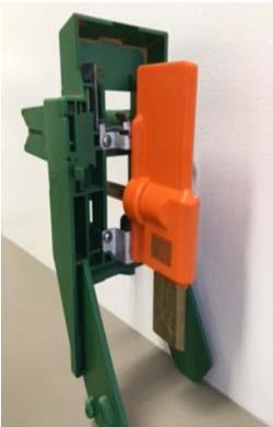
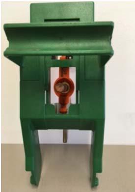
21 A7 Underground conductor clamp A8 Typical underground low voltage short circuit installation shorts applied by means of copper stalks inserted in the service termination blocks NW000-S0062 UNCONTROLLED IF PRINTED Page 21 of 33


22 Annexure B LV short circuits bar codes / tags / labels B1 LV short circuit inspection labels NW000-S0062 UNCONTROLLED IF PRINTED Page 22 of 33
23 B2 LV short circuit inspection labels Replacement inspection labels are available from Workshop Manager - Homebush NW000-S0062 UNCONTROLLED IF PRINTED Page 23 of 33


 with")

24 Annexure C UG LV short circuits fittings C1 Low voltage link box / pillar arrangements C2 Commercial & industrial pillar (Jean Muller SL3-3X/ 3AA2 LTL4A, Size: NH4a, Rated I: 1250A) with NH-type DIN link connectors NW000-S0062 UNCONTROLLED IF PRINTED Page 24 of 33


25 C3 Approved connection adaptors Suitable for SAIF MKII LV fuse strips Suitable for Jean Muller LV fuse strips Suitable for Webber LV fuse strips NW000-S0062 UNCONTROLLED IF PRINTED Page 25 of 33


")


26 C4 Customer Meter/ Switch Board Modular fuse holders (Cooper Bussmann HSB30BWI 100A) C5 Heading locking test links NW000-S0062 UNCONTROLLED IF PRINTED Page 26 of 33


27 C6 Copper stalks for LV service termination blocks NW000-S0062 UNCONTROLLED IF PRINTED Page 27 of 33


28 Annexure D OH LV ABC Short Circuits fittings D1 Typical IPC SICAME Australia LV connector product number EPC1-401 NW000-S0062 UNCONTROLLED IF PRINTED Page 28 of 33
29 Annexure E LV Short Circuit Form E1 LV Short Circuit Form. NW000-S0062 UNCONTROLLED IF PRINTED Page 29 of 33

30 E2 LV Short Circuit Form Overhead example NW000-S0062 UNCONTROLLED IF PRINTED Page 30 of 33

31 E3 LV Short Circuit Form Underground example NW000-S0062 UNCONTROLLED IF PRINTED Page 31 of 33

32 Annexure F Sample Compliance Checklist NW000-S0062 UNCONTROLLED IF PRINTED Page 32 of 33
33 NW000-S0062 UNCONTROLLED IF PRINTED Page 33 of 33
ACCESS TO HIGH VOLTAGE APPARATUS
 CORPORATE PROCEDURE ACCESS TO HIGH VOLTAGE APPARATUS Approved By: Prepared By: Issue Date: 17/6/2011 Andrew Macrides Access to Apparatus Rules File No: Managing Director Committee QDOC2011/63 Status: Approved
EDS LV SUPPLIES TO MOBILE PHONE BASE STATIONS MOUNTED ON TRANSMISSION TOWERS
 ENGINEERING DESIGN STANDARD EDS 08-2109 LV SUPPLIES TO MOBILE PHONE BASE STATIONS MOUNTED ON TRANSMISSION TOWERS Network(s): Summary: EPN, LPN, SPN This standard provides guidance on the installation of
Field Instruction Switching Activities. Purpose. Scope. Objective. Safety
 8.22 Switching Activities Purpose This instruction provides a safe system for switching on Horizon Powers Low Voltage, High Voltage and or Transmission electrical apparatus/network, where switching operations
Field Instruction. Induced voltages can occur in overhead lines, underground cables, or in switchyards.
 8.3 Induced Voltage Purpose The purpose of this instruction is to provide awareness of Electrostatic and Electromagnetic induced voltages and the method required to reduce or eliminate it. An induced voltage
ECP HV INSULATION TESTING
 Document Number: ECP 11-0006 Network(s): Summary: All ENGINEERING COMMISSIONING PROCEDURE ECP 11-0006 HV INSULATION TESTING This standard details the policy for the on-site insulation testing of new and
EI HIGH VOLTAGE INSULATION TESTING POLICY
 Network(s): Summary: ENGINEERING INSTRUCTION EI 09-0001 HIGH VOLTAGE INSULATION TESTING POLICY EPN, LPN, SPN This engineering instruction details the policy for the on-site insulation testing of new and
Earthing, HV Switching and Associated Operational Equipment. Approval: Chief Operating Officer
 ACCESS PRACTICE AP 24 Earthing, HV Switching and Associated Operational Equipment Process Authority: Manager Operations Improvement Approval: Chief Operating Officer Version Date: 27/08/2013 Revision:
Network Standard NS
 Network Standard NS 21-2006 Artwork on Western Power Assets Technical Requirements for application to South West Interconnected System (SWIS) DMS #1049174 NS 21-2006 Artwork on Western Power Assets REVISION
ECP HV INSULATION TESTING
 Document Number: ECP 11-0006 Network(s): Summary: ENGINEERING COMMISSIONING PROCEDURE EPN, LPN, SPN ECP 11-0006 HV INSULATION TESTING This standard details the policy for the on-site insulation testing
SDCS-03 DISTRIBUTION NETWORK GROUNDING CONSTRUCTION STANDARD (PART-I) UNDERGROUND NETWORK GROUNDING. Rev. 01
 UNDERGROUND NETWORK GROUNDING. Rev. 01") SDCS-03 DISTRIBUTION NETWORK GROUNDING CONSTRUCTION STANDARD (PART-I) UNDERGROUND NETWORK GROUNDING Rev. 01 This specification is property of SEC and subject to change or modification without any notice
SDCS-03 DISTRIBUTION NETWORK GROUNDING CONSTRUCTION STANDARD (PART-I) UNDERGROUND NETWORK GROUNDING Rev. 01 This specification is property of SEC and subject to change or modification without any notice
Customer Requirements RF Antenna Installations
 Application Terms Attachment requirements and clearances on the Pole for Radio Frequency (RF) antenna equipment installations. This standard is intended to allow electrical workers to perform their normal
NSP/004/107 (OHI 7) Guidance on the selection of conductor jumpers and non-tension connections
 Guidance on the selection of conductor jumpers and non-tension connections") Version:- 3.0 Date of Issue:- September 2015 Page 1 of 12 NSP/004/107 (OHI 7) Guidance on the selection of conductor jumpers and non-tension connections 1. Purpose The purpose of this document is to provide
Version:- 3.0 Date of Issue:- September 2015 Page 1 of 12 NSP/004/107 (OHI 7) Guidance on the selection of conductor jumpers and non-tension connections 1. Purpose The purpose of this document is to provide
Collection of standards in electronic format (PDF) 1. Copyright
 1. Copyright") Collection of standards in electronic format (PDF) 1. Copyright This standard is available to staff members of companies that have subscribed to the complete collection of SANS standards in accordance
Collection of standards in electronic format (PDF) 1. Copyright This standard is available to staff members of companies that have subscribed to the complete collection of SANS standards in accordance
Guideline for Creating Disconnection Points and Establishing a Not Electrically Connected Area
 Guideline for Creating Disconnection Points and Establishing a Not Document Number: Authorised by: Issue Date: 29 June 2012 Previous Document: 12 February 2010 Principal Authors: J Dohmen Powerlink D Brown
DESIGN PRACTICE NOTE DESIGN/REVIEW REQUIREMENTS FOR TRACTION BONDING PLAN
 Approval Amendment Record Approval Date Version Description 01/04/2014 1 Initial Issue under MTM PRINTOUT MAY NOT BE UP-TO-DATE; REFER TO METRO INTRANET FOR THE LATEST VERSION Page 1 of 7 Table of Contents
ECP DISTRIBUTION TRANSFORMER COMMISSIONING PROCEDURE
 Document Number: ECP 11-0506 ENGINEERING COMMISSIONING PROCEDURE ECP 11-0506 DISTRIBUTION TRANSFORMER COMMISSIONING PROCEDURE Network(s): Summary: EPN, LPN, SPN This procedure details the testing and commissioning
ECP COMPACT AND MICRO SUBSTATION COMMISSIONING PROCEDURE
 Network(s): Summary: ENGINEERING COMMISSIONING PROCEDURE ECP 11-0507 COMPACT AND MICRO SUBSTATION COMMISSIONING PROCEDURE EPN, LPN, SPN This procedure details the testing and commissioning procedures for
NPS/002/016 Technical Specification for 33 kv Cable Joints and Terminations
 Version: 3.1 Date of Issue: September 2016 Page: 1 of 21 NPS/002/016 Technical Specification for 33 kv Cable Joints and Terminations 1. Purpose The purpose of this document is to detail the technical requirements
Instructions for Installation. S&C ELECTRIC COMPANY Specialists in Electric Power Switching and Protection TABLE OF CONTENTS INTRODUCTION INSTALLATION
 S&C Alduti-Rupter Switches Outdoor Distribution Three-Pole Double-Break Style and Three-Pole Double-Break Integer Style Live Parts Replacement on Switches with Catalog Number Supplement -R10 34.5 kv and
Company Directive STANDARD TECHNIQUE: SD5F. Relating to connecting multiple small low voltage connections with limited network analysis
 Company Directive STANDARD TECHNIQUE: SD5F Relating to connecting multiple small low voltage connections with limited network analysis Policy Summary This document specifies the procedure for connecting
FAQ ON EARTHING STANDARDS 16/08/2018
 FAQ ON EARTHING STANDARDS 16/08/2018 This document has been updated to include changes made to substation earthing layouts that have been made necessary due to copper theft. The main changes to be aware
Earthing Guidance Notes
 Central Networks Earthing Manual Section E2 Earthing Guidance Notes Version: 2 Date of Issue: September 2007 Author: Nigel Johnson Job Title: Earthing Specialist Approver: John Simpson Job Title: Head
METER - INSTALLATION Pad Mount Transformer
 ER 1-210-C PAGE 1 OF 5 USE: Pad mount transformer secondary compartment LATEST REVISION: PREVIOUS REVISION 10-01-12 ORIGINATED 0-94 PREVIOUS NUMBER ER 700, 10-01-86 Added specification for placement and
SUBJECT HEADING: Switching Programmes ISSUE: 18
 SUBJECT: Switchgear/Switching PROCEDURE: S04 SUBJECT HEADING: Switching Programmes ISSUE: 18 DATE: Apr 2017 1. INTRODUCTION 1.1 A written programme of switching operations shall be prepared. This programme
CSEE UM71 AF Jointless Track Circuits Set-up, Test and Certification
 Discipline: Engineering (Signalling) Category: Standard CSEE UM71 AF Jointless Track Circuits Set-up, Test and Certification SES 06 Applicability New South Wales CRIA (NSW CRN) Primary Source RIC Standard
WB&S FS2500 AF Jointless Track Circuits Set-Up, Test and Certification
 Discipline: Engineering (Signalling) Category: Standard WB&S FS2500 AF Jointless Track Circuits Set-Up, Test and Certification SES 07 Applicability New South Wales CRIA (NSW CRN) Primary Source RIC Standard
SERVICING & METERING SERVICING AND METERING SECTION 5 SEC5:
 SECTION SERVICING AND METERING SECTION 1. SERVICING.... NST IMPEDANCE TESTING.... METERING... General Requirements.... CT METERING... 8 CT Metering General Requirements... 8 Existing Installation Alterations
Endeavour Energy Electrical Safety Rules. October 2013
 Endeavour Energy Electrical Safety Rules October 2013 Endeavour Energy Electrical Safety Rules Associated Procedures List Document No. Title GSY 0031 Operating or observing plant near overhead electrical
2/15/2015. Current will always try to return to its source. In order for there to be current, there must be a complete circuit
 Current will always try to return to its source In order for there to be current, there must be a complete circuit Current will take as many paths or circuits available to it to return to the source The
SAFETY AND HEALTH STANDARD ELECTRICAL GROUNDING Effective Date: 07/17/10 Standard: Document Number: KUCSH0039 Rev: 4
 SAFETY AND HEALTH STANDARD ELECTRICAL GROUNDING Effective Date: 07/17/10 Standard: 16.10 Document Number: KUCSH0039 Rev: 4 16.10.1 INTRODUCTION 16.10.1.1 The intent of this standard is to ensure that continuity
IMP/010/011 Code of Practice for Earthing LV Networks and HV Distribution Substations
 Version:- 3.0 Date of Issue:- January 2018 Page 1 of 70 IMP/010/011 Code of Practice for Earthing LV Networks and HV Distribution Substations 1. Purpose The purpose of this document is to ensure the company
MESP TECHNICAL SPECIFICATION FOR AN ESSENTIAL SERVICES SUPPLY STEP UP TRANSFORMER
 Engineering Specification TECHNICAL SPECIFICATION FOR AN ESSENTIAL Version: 3 Issued: 14 October 2016 Owner: Chief Engineer Approved By: Andrew Russack Head of Engineering - Electrical PRINTOUT MAY NOT
Cable Identifying Generator LCI TX / LCI TX-440
 Operation manual Cable Identifying Generator LCI TX / LCI TX-440 Mess- und Ortungstechnik Measuring and Locating Technologies Elektrizitätsnetze Power Networks Kommunikationsnetze Communication Networks
Distribution transformers Part 2 Ground mounted transformers not closecoupled
 PRODUCED BY THE OPERATIONS DIRECTORATE OF ENERGY NETWORKS ASSOCIATION Technical Specification 35-1 Distribution transformers Part 2 Ground mounted transformers not closecoupled www.energynetworks.org PUBLISHING
Electrical Procedure No E032. Procedure No: ELE 032
 Procedure No: ELE 032 Procedure Title: Date of Procedure: Responsible Person(s) Safety Isolation of Low Voltage Networks and Systems for work to be carried out by third parties. i.e. Non University personnel.
American Electrical Institute
 American Electrical Institute Oregon Electricians Continuing Education Grounding & Bonding (Article 250) 4 Hours American Electrical Institute PO Box 31131 Spokane, WA 99223 www.aeitraining.com Article
FINAL - ER 70 Electrician Regulations Answer Schedule. Question 1 Marks Reference Marking notes
 FINAL - ER 70 Electrician Regulations Answer Schedule Notes:1. (1 mark) means that the preceding statement/answer earns 1 mark. 2. This schedule sets out the expected answers to the examination questions.
TS RES - OUTSTANDING ISSUES
 TS RES - OUTSTANDING ISSUES This document has been officially issued as DRAFT until the following outstanding issues have been resolved. At that time the document will be officially reissued as the next
SDCS-03 DISTRIBUTION NETWORK GROUNDING CONSTRUCTION STANDARD (PART-II) OVERHEAD NETWORK GROUNDING. Rev. 01
 OVERHEAD NETWORK GROUNDING. Rev. 01") SEC DISTRIBUTION GROUNDING STANDARD SDCS-03 Part-II Rev.01 SDCS-03 DISTRIBUTION NETWORK GROUNDING CONSTRUCTION STANDARD (PART-II) OVERHEAD NETWORK GROUNDING Rev. 01 This specification is property of SEC
SEC DISTRIBUTION GROUNDING STANDARD SDCS-03 Part-II Rev.01 SDCS-03 DISTRIBUTION NETWORK GROUNDING CONSTRUCTION STANDARD (PART-II) OVERHEAD NETWORK GROUNDING Rev. 01 This specification is property of SEC
Australian Standard. Switchgear assemblies and ancillary equipment for alternating voltages above 1 kv AS
 AS 2067 1984 Australian Standard Switchgear assemblies and ancillary equipment for alternating voltages above 1 kv [Title allocated by Defence Cataloguing Authority: SWITCHGEAR ASSEMBLIES, ELECTRICAL AND
ML TI21 AF Jointless Track Circuits Set Up, Test and Certification
 Discipline: Engineering (Signalling) Category: Standard ML TI21 AF Jointless Track Circuits Set Up, Test and Certification SES 08 Applicability New South Wales CRIA (NSW CRN) Primary Source RIC Standard
Elderfield & Hall, Inc., Kama Bandsaw AD 105S. Instruction Manual: Introduction to the Manual. General Precautions. Equipment. Machine.
 Elderfield & Hall, Inc., www.kooltools.com 10901 McBride Lane, Knoxville TN, 37932. Phone: 865.671.7682. Fax: 865.671.7686. Email: bob@kooltools.com Kama Bandsaw AD 105S 110 Volt, Single Phase 2 ¼ HP Portable
Variable Pitch Collector Frame
 Variable Pitch Collector Frame INSTALLATION INSTRUCTIONS FOR SOLAR WATER HEATER SYSTEMS This frame must be installed by an authorised person. Please leave this guide with a responsible officer or the householder.
UNCONTROLLED COPY. Queensland Electricity Entity Standard for Safe Access to High Voltage Electrical Apparatus. August 2015
 Queensland Electricity Entity Standard for Safe Access to High Voltage Electrical Apparatus August 2015 August 2015 Queensland Electricity Entity Standard for Safe Access to HV Electrical Apparatus I This
TABLE OF CONTENTS FOREWORD... 3 INTRODUCTION SCOPE NORMATIVE REFERENCES... 4
 TITLE SPECIFICATION FOR CRIMPED CONNECTING LUGS AND FERRULES PAGE: 1 OF 29 ISION DATE: SEPTEMBER 2014 TABLE OF CONTENTS Page FOREWORD... 3 INTRODUCTION... 4 1 SCOPE... 4 2 NORMATIVE S... 4 3 REQUIREMENTS...
iant200 iant212 iant213 iant214 iant215 iant216 iant217 iant218 iant219 iant220 iant221 iant222 Operating Manual iant2xx Series of Antennas
 iant200 iant212 iant213 iant214 iant215 iant216 iant217 iant218 iant219 iant220 iant221 iant222 Operating Manual iant2xx Series of Antennas This page is intentionally left blank. Document Number 403449
Status Date Prepared Reviewed Endorsed Approved
 Discipline Engineering Standard - NSW Category Signalling Title Reference Number SPS 19 - (RIC Standard: SC 07 40 04 00 SP) Document Control Status Date Prepared Reviewed Endorsed Approved May 05 Standards
NPS/001/010 Technical Specification for Fasteners and Fixings for Wood Pole Overhead Lines and General Construction Works
 Version:- 4.0 Date of Issue:- August 2014 Page 1 of 13 NPS/001/010 Technical Specification for Fasteners and Fixings for Wood Pole Overhead Lines and General Construction Works 1. Purpose The purpose of
National Marine Manufacturers Association Compliance Specialist Examination A.C. Electrical (2018 Model Year) ABYC E-11 Supplement 56
 ABYC E-11 Supplement 56") 1. Two Electrical Technicians are discussing markings that are required for AC wiring. Tech A says that AC conductors must be rated for 600 volts and must have their jackets and individual conductors marked
1. Two Electrical Technicians are discussing markings that are required for AC wiring. Tech A says that AC conductors must be rated for 600 volts and must have their jackets and individual conductors marked
Installation & Operating Manual. iwap202
 Installation & Operating Manual iwap202 This page is intentionally left blank. Document Number 409345 (based on 407655) (See Last Page for Revision Details) For warranty information, refer to Terms and
Licensed Electricians Practical Assessment (LEP)
") Licensed Electricians Practical Assessment (LEP) Surname: Date: Given Names: Time: Assessment Time (includes 10 minutes reading time): At the end of this time you will be asked to stop. 4 hours Have you
Licensed Electricians Practical Assessment (LEP) Surname: Date: Given Names: Time: Assessment Time (includes 10 minutes reading time): At the end of this time you will be asked to stop. 4 hours Have you
MESP TECHNICAL SPECIFICATION FOR AN AUXILIARY OR ESSENTIAL SERVICES AND AUXILIARY TRANSFORMER FOR USE IN A RAILWAY SUBSTATION
 Engineering Specification Head of Electrical Engineering MESP 050100-01 TECHNICAL SPECIFICATION FOR AN AUXILIARY OR ESSENTIAL SERVICES AND AUXILIARY TRANSFORMER FOR USE IN A RAILWAY SUBSTATION Version:
Nemalux INSTALLATION INSTRUCTIONS APPLICATION 1-4
 I N D U S T R I A L rev. A- INSTALLATION INSTRUCTIONS *PENDING* E77827 E77827 APPLICATION MR3 & MR6 Luminaires are suitable for use in the following areas as defined by the National Electrical Code (NEC)
Table of Contents. Introduction... 1
 Table of Contents Introduction... 1 1 Connection Impact Assessment Initial Review... 2 1.1 Facility Design Overview... 2 1.1.1 Single Line Diagram ( SLD )... 2 1.1.2 Point of Disconnection - Safety...
Article 250 Grounding & Bonding
 Article 250 Grounding & Bonding AMERICAN ELECTRICAL INSTITUTE N16 W23217 Stone Ridge Dr. Waukesha, WI 53188 855-780-5046 www.aeitraining.com DISCLAIMER NOTE: This course is APPROVED for continuing education
Reference Number PDS 07 (RIC Standard: EP SP)
") Discipline Engineering Standard NSW Category Electrical Title Reference Number PDS 07 (RIC Standard: EP 12 10 00 20 SP) Document Control Status Date Prepared Reviewed Endorsed Approved Jan 05 Standards
Discipline Engineering Standard NSW Category Electrical Title Reference Number PDS 07 (RIC Standard: EP 12 10 00 20 SP) Document Control Status Date Prepared Reviewed Endorsed Approved Jan 05 Standards
National Grid UK Electricity Transmission plc. NATIONAL SAFETY INSTRUCTION and Guidance
 National Grid UK Electricity Transmission plc NATIONAL SAFETY INSTRUCTION and Guidance NSI 26 RAILWAY CONNECTION CIRCUITS Copyright National Grid plc 2016, all rights reserved. No part of this publication
CONTINUING EDUC ATION
 3 CONTINUING EDUC ATION FOR WISCONSIN ELECTRICIANS 2017 NEC Article 250 2 Hours WISCONSIN CONTRACTORS INSTITUTE N16 W23217 Stone Ridge Drive Suite 290 Waukesha, WI 53188 262-409-4282 www.wcitraining.com
Suppliers' Information Note. BT Metallic Path Facility. Interface Description
 SIN 349 Issue 2.5 August 2015 Suppliers' Information Note For The BT Network BT Metallic Path Facility Interface Description Each SIN is the copyright of British Telecommunications plc. Reproduction of
Connection of Embedded Generating Plant up to 5MW
 Engineering Recommendation No.3 of the Electricity Distribution Code Connection of Embedded Generating Plant up to 5MW Version 1.0 30th November 2005 Prepared by: Al Ain Distribution Company, Abu Dhabi
S&C Scada-Mate Switching Systems Outdoor Distribution Interrupter Replacement 14.4 kv through 34.5 kv
 S&C Scada-Mate Switching Systems Outdoor Distribution Interrupter Replacement 14.4 kv through 34.5 kv Instructions for Field Replacement TABLE OF CONTENTS Section Page Section Page INTRODUCTION Qualified
Reference Number PCP 02 (RIC Standard: EP SP)
") Discipline Engineering Standard NSW Category Electrical Title Reference Number PCP 02 (RIC Standard: EP 20 00 00 20 SP) Document Control Status Date Prepared Reviewed Endorsed Approved Mar 05 Standards
Discipline Engineering Standard NSW Category Electrical Title Reference Number PCP 02 (RIC Standard: EP 20 00 00 20 SP) Document Control Status Date Prepared Reviewed Endorsed Approved Mar 05 Standards
GURANTEED TECHNICAL PARTICULARS OF BACK CLAMP FOR LT CROSS ARM
 Technical Specification of Back Clamp for LT Cross Arm (MS) Back clamp for LT Cross Arm made out of 50 x 6mm MS Flat suitable for 8m X 300 Kg PSC poles. After fabrication the cross arm shall be painted
Australian Standard. Electricity metering equipment (AC) Particular requirements. Part 22: Static meters for active energy (classes 0.2 S and 0.
 Particular requirements. Part 22: Static meters for active energy (classes 0.2 S and 0.") AS 62053.22 2005 IEC 62053-22, Ed.1.0 (2003) AS 62053.22 2005 Australian Standard Electricity metering equipment (AC) Particular requirements Part 22: Static meters for active energy (classes 0.2 S and
AS 62053.22 2005 IEC 62053-22, Ed.1.0 (2003) AS 62053.22 2005 Australian Standard Electricity metering equipment (AC) Particular requirements Part 22: Static meters for active energy (classes 0.2 S and
AMPSEAL* Automotive Plug Connector and Header Assembly
 AMPSEAL* Automotive Plug Connector and Header Assembly Application Specification 114-16016 17 APR 14 NOTE NOTE i All numerical values are in metric units [with U.S. customary units in brackets]. Unless
Title Substation Auxiliary Transformer from Rectifier Transformer Secondary. Reference Number PDS 01 (RIC Standard: EP SP)
") Discipline Engineering Standard NSW Category Electrical Title Substation Auxiliary Transformer from Rectifier Transformer Secondary Reference Number PDS 01 (RIC Standard: EP 05 00 00 01 SP) Document Control
Discipline Engineering Standard NSW Category Electrical Title Substation Auxiliary Transformer from Rectifier Transformer Secondary Reference Number PDS 01 (RIC Standard: EP 05 00 00 01 SP) Document Control
GK/GN0653. Guidance on Control of Unwanted Voltages on Telecommunications. Equipment at Stations. Rail Industry Guidance Note for GK/RT0053
 GN Published by: Block 2 Angel Square 1 Torrens Street London EC1V 1NY Copyright 2011 Rail Safety and Standards Board Limited GK/GN0653 Telecommunications Equipment at Stations Issue One: December 2011
IMP/007/011 - Code of Practice for the Application of Lightning Protection
 Version 1.1 of Issue Aug 2006 Page 1 of 11 IMP/007/011 - Code of Practice for the Application of Lightning Protection 1.0 Purpose The purpose of this document is to ensure the company achieves its requirements
Reference Number PPS 05 - (RIC Standard: EP SP)
") Discipline Engineering Standard - NSW Category Electrical Title Low Voltage Isolating Transformer Reference Number PPS 05 - (RIC Standard: EP 17 00 00 11 SP) Document Control Status Date Prepared Reviewed
Discipline Engineering Standard - NSW Category Electrical Title Low Voltage Isolating Transformer Reference Number PPS 05 - (RIC Standard: EP 17 00 00 11 SP) Document Control Status Date Prepared Reviewed
Licensed Electricians Practical Assessment (LEP)
") Licensed Electricians Practical Assessment (LEP) Surname: Given Names: Date: Time: Location: Assessment Time (includes reading and preparation time): At the end of this time you will be asked to stop.
Licensed Electricians Practical Assessment (LEP) Surname: Given Names: Date: Time: Location: Assessment Time (includes reading and preparation time): At the end of this time you will be asked to stop.
ECP HV METERING EQUIPMENT COMMISSIONING PROCEDURE
 THIS IS AN UNCONTROLLED DOCUMENT, THE READER MUST CONFIRM ITS VALIDITY BEFORE USE Document Number: ECP 11-0515 ENGINEERING COMMISSIONING PROCEDURE ECP 11-0515 HV METERING EQUIPMENT COMMISSIONING PROCEDURE
INSTALLATION & TESTING OF UNDERGROUND PRIMARY AND SECONDARY POWER CABLES PRIOR TO ENERGIZATION
 TITLE: RECOMMENDED: P. Lemay NO: APPROVED: C. Malone, P.Eng. REV. DATE: 2015-11-02 Working Procedure GCG0001 REV: 3 INSTALLATION & TESTING OF UNDERGROUND PRIMARY AND SECONDARY POWER CABLES PRIOR TO ENERGIZATION
Risk Assessment & Safe Working Practice
 RA Ref Number: 46 Revision: 3 Project/Job Number Reference Insert Job Number Approval Date: 30/03/2018 RA Description: Electrical Termination Pyro Next Review Date: 01/04/2019 Notes: Please refer to Safe
H HD Adult Wheelchair Swing Frame & Hangers(perm) IMPORTANT
 IMPORTANT") Page 1 IMPORTANT PLEASE READ THESE INSTRUCTIONS BEFORE COMMENCING ASSEMBLY. All equipment must be installed in accordance with these instructions. Check your shipment against Bill of Lading and Parts list.
Page 1 IMPORTANT PLEASE READ THESE INSTRUCTIONS BEFORE COMMENCING ASSEMBLY. All equipment must be installed in accordance with these instructions. Check your shipment against Bill of Lading and Parts list.
MC CHANGER CABINET INSTALLATION INSTRUCTIONS
 8M00356 REV. 10 www.standardchange.com 1-800-968-6955 Technical Phone Support is from 8:00AM to 7:30PM E.S.T., Monday-Friday Walk-in Service is from 8:00AM to 4:30PM E.S.T., Monday-Friday Parts Department
Machine Guards White Paper 1 Fixings for Fixed Guards 1st Edition November 2013
 Machine Guards White Paper 1 Fixings for Fixed Guards 1st Edition November 2013 How to specify fixings for machine guards Jeremy Procter, a Member of BSI's MCE/3 committee, former Convenor of the European
PREFACE ********************************************************** IT IS NOT INTENDED THAT THESE STANDARDS BE COPIED AND USED AS A SPECIFICATION!
 PREFACE This publication has been prepared as a guide for Architectural and Engineering (A&E) firms in the preparation of documents for the design and construction of new structures and the remodeling
Reference Number PDS 04 (RIC Standard: EP SP)
") Discipline Engineering Standard NSW Category Electrical Title Reference Number PDS 04 (RIC Standard: EP 12 10 00 10 SP) Document Control Status Date Prepared Reviewed Endorsed Approved Mar 05 Standards
Discipline Engineering Standard NSW Category Electrical Title Reference Number PDS 04 (RIC Standard: EP 12 10 00 10 SP) Document Control Status Date Prepared Reviewed Endorsed Approved Mar 05 Standards
Digital Voltage Detector 0-999kV Operating Instructions VD1000PTM
 Digital Voltage Detector 0-999kV Operating Instructions VD1000PTM CONTENTS Limitation of Warranty and Liability 2 Product Safety Information 3 Design and Function Battery Replacement 4 Voltage Detection
FINAL - EST Electrical Service Technician Answer Schedule
 FINAL - EST 2069 - Electrical Service Technician Answer Schedule Notes:1. means that the preceding statement/answer earns 1 mark. 2. This schedule sets out the accepted answers to the examination questions.
Section 3. Test Procedures
 Section 3. Information contained within this section shall be read in conjunction with all sections of this manual Non - Compliant Test Results Where acceptable results are not attained in accordance with
Operators Manual: Diamond Rock Saw Excavator Attachment Austramac Flashcut Series
 Operators Manual: Diamond Rock Saw Excavator Attachment Austramac Flashcut Series! WARNING! Inappropriate use of rock saw may cause serious injury or death. Operators must read this manual before use and
AS/NZS CISPR 14.2:2015
 AS/NZS CISPR 14.2:2015 (CISPR 14-2, Ed. 2.0:2015, IDT) Australian/New Zealand Standard Electromagnetic compatibility Requirements for household appliances, electric tools and similar apparatus Part 2:
INTERPLANT STANDARD - STEEL INDUSTRY
 INTERPLANT STANDARD - STEEL INDUSTRY SPECIFICATION FOR MOULDED - CASE CIRCUIT-BREAKER FOR VOLTAGES NOT EXCEEDING 1000 V ac OR 1500 V dc (FIRST REVISION) IPSS:1-04-004-11 IPSS BASED ON IS/IEC 60947(Part
Wisconsin Contractors Institute Continuing Education
 IMPORTANT NOTE: You should have received an email from us with a link and password to take your final exam online. Please check your email for this link. Be sure to check your spam folder as well. If you
HIGH VOLTAGE PHASE COMPARATORS
 USER'S MANUAL for HIGH VOLTAGE PHASE COMPARATORS PC Series Double Poles Model System Voltage Full Scale MT6k 6.6kV 8kV MT11k 11kV 12kV MT22k 22kV 24kV MT33k 33kV 36kV MT44k 44kV 48kV Exceeds VDE681-5 /
Neutral Earthing. For permanent or temporary neutral earthing in HV systems
 Neutral Earthing Resistors RESISTORS For permanent or temporary neutral earthing in HV systems For continuous or temporary low-resistance neutral grounding in medium voltage systems Neutral point connection
OAK GROVE PLANT MAINTENANCE SECTION-MECHANICAL
 UNIT 1 PULVERIZER SYSTEM SEMI-ANNUAL INSPECTION OG-MSM-229 EFFECTIVE DATE: PREPARED BY (Print): TOM PERSON 8/31/21 EXT: 6395 TECHNICAL REVIEW BY (Print): EXT: APPROVED BY: DATE: OG-MSM-229 PAGE 2 OF 24
RELEVANT ELECTRICAL STANDARDS
 RELEVANT ELECTRICAL STANDARDS Issue 2 February 2014 National Grid 2014 No part of this publication may be reproduced, stored in a retrieval system, or transmitted in any form or by any means electronic,
UNIVERSITY OF MISSOURI Liquid-Filled Utility Transformers 2016 Q1
 GENERAL: The scope of this document is to provide instruction for the installation and testing of Medium Voltage, 3 Phase, Pad Mounted Transformers installed at the University of Missouri. Preferred transformers
HIGH VOLTAGE RULES. Document Owner: HV Group. Authorised: Electrical Services Manager Liberty Primary Steel
 HIGH VOLTAGE RULES Document Owner: HV Group Authorised: Electrical Services Manager Liberty Primary Steel HIGH VOLTAGE RULES Revision 10 INDEX 1.0 GENERAL 1.1 SCOPE 1.2 DUTIES 1.3 SUPPLY AND KNOWLEDGE
Schluter -DITRA-HEAT Repair procedure for the DHE-HK Heating Cable
 Schluter -DITRA-HEAT Repair procedure for the DHE-HK Heating Cable 555758 03/2018 2018 Schluter Systems L.P. DITRA and HEAT E are registered trademarks of Schluter Systems CONTENTS 3 List of tools required
Your safety first! This is the reason why our manual begins with the following guidelines:
 High Voltage Products Current Transformers PA 123a and PA 145a Installation and operation manual Your safety first! This is the reason why our manual begins with the following guidelines: Use the transformer
Les Hampson Cert Ed FSCTE, Chairman CAI Technical Committee
 Making the Bond Les Hampson Cert Ed FSCTE, Chairman CAI Technical Committee After many man hours of deliberation and consultation the Code of Practice Electrical Safety Requirements for Signal Reception
11-SDMS-03 REV. 02 SPECIFICATIONS FOR
 11-SDMS-03 REV. 02 SPECIFICATIONS FOR XLPE INSULATED POWER CABLES FOR RATED VOLTAGES FROM 15 KV UP TO 36 KV (U m ) This specification is property of SEC and subject to change or modification without notice
Self-assembly and pole conversion system
 User Manual Self-assembly and pole conversion system Swivelpole R11, R12 and R13 for self-assembly of lowering poles on greenfield projects or conversion of non-lowering poles on brownfield facilities.
MEDIUM VOLTAGE TERMINATIONS CATALOGUE 2017
 MEDIUM VOLTAGE TERMINATIONS CATALOGUE 01 NEXANS NETWORK SOLUTIONS DIV. EUROMOLD COMPANY PRESENTATION EUROMOLD Euromold is the leading European specialised designer, manufacturer and distributor of prefabricated
Company Directive STANDARD TECHNIQUE: SD1E/2. Technical Requirements for Customer Export Limiting Schemes
 Company Directive STANDARD TECHNIQUE: SD1E/2 Technical Requirements for Customer Export Limiting Schemes Policy Summary This Standard Technique specifies the requirements for customer owned Export Limitation
Title Operating Work - Low Voltage Distribution System. Reference Number POP 06 - (RIC Standard: EP SI)
") Discipline Engineering Standard - NSW Category Electrical Title Operating Work - Low Voltage Distribution System Reference Number POP 06 - (RIC Standard: EP 95 30 00 03 SI) Document Control Status Date
Discipline Engineering Standard - NSW Category Electrical Title Operating Work - Low Voltage Distribution System Reference Number POP 06 - (RIC Standard: EP 95 30 00 03 SI) Document Control Status Date
Revision 24 of Issue 3 of the Grid Code has been approved by the Authority for implementation on 19 th November 2007.
 Our Ref: Your Ref: Date: November 2007 To: All Recipients of the Serviced Grid Code Regulatory Frameworks Electricity Codes National Grid Electricity Transmission plc National Grid House Warwick Technology