Operator's Manual A1000. Applicator. Made in Germany
|
|
|
- Ilene Atkins
- 6 years ago
- Views:
Transcription


1 Operator's Manual Applcator A1000 Made n Germany
2 2 Operator's Manual - Translaton of the Orgnal Verson 2 for the followng products Famly A1000 Edton: 03/ Part No Copyrght Ths documentaton as well as translaton hereof are property of cab Produkttechnk GmbH & Co. KG. The replcaton, converson, duplcaton or dvulgement of the whole manual or parts of t for other ntentons than ts orgnal ntended purpose demand the prevous wrtten authorzaton by cab. Edtor Regardng questons or comments please contact cab Produkttechnk GmbH & Co. KG. Topcalty Due to the constant further development of our products dscrepances between documentaton and product can occur. Please check for the latest update. Terms and condtons Delveres and performances are effected under the General condtons of sale of cab. Germany cab Produkttechnk GmbH & Co KG Postfach 1904 D Karlsruhe Wlhelm-Schckard-Str. 14 D Karlsruhe Telefon Telefax nfo@cab.de France cab technologes s.a.r.l. F Nedermodern Téléphone nfo.fr@cab.de Representatves n other countres on request USA cab Technology Inc. Tyngsboro MA, Phone nfo.us@cab.de Asa cab Technology Co., Ltd. Junghe, Tape, Tawan Phone nfo.asa@cab.de Chna cab (Shangha)Tradng Co., Ltd. Phone nfo.cn@cab.de
3 Table of Contents 3 1 Introducton Instructons Intended Use Safety Instructons Safety Markng Envronment Product Descrpton Functon Important Features Techncal Data Devce Overvew Pads Tamp Pads Roll-on Pads Blow Pads Installaton Contents of Delvery Mountng the Applcator to the Prnter Percng the Unversal Tamp Pad Preparng the Applcator for Usng a Tamp Pad Type Mountng the Pad Mountng the Stopper Connectons Confguraton Method for Changng the Prnter Setup Quck Mode for Settng the Delay Tmes Confguraton Parameters of the Applcator Adjustments Mechancal Adjustments Algnng the Pad Adjustng the Parallelsm between Pad and Dspense Edge Openng the Holes on the Blow Tube Algnng the Blow Tube Adjustng the Stopper Pneumatc Adjustments Control Valves Adjustng the Pad Movement Speed Adjustng Vacuum and Supportng Ar Opton Pressure Reducton Valve Operaton Loadng Labels and Transfer Rbbon Actvaton of Peel-off Mode Settng the Peel Poston Test Mode Usng the Pre-dspense Key wthout Prnt Job Test Mode Usng the Pre-dspense Key wth Prnt Job Standard Operaton PLC Interface Pn Assgnment and Sgnal Descrpton Crcut Dagrams of Inputs and Outputs Examples for External Crcuts Error Messages Error Messages of the Prnter Error Messages of the Applcator Functon of the LED n the electroncs of the applcator Declaraton Declaraton of Incorporaton EU Declaraton of Conformty Index... 32
4 4 1 Introducton Instructons Important nformaton and nstructons n ths documentaton are desgnated as follows: Danger! Draws your attenton to an exceptonally grave, mpendng danger to your health or lfe.! Warnng! Indcates a hazardous stuaton that could lead to njures or materal damage.! Attenton! Draws attenton to possble dangers, materal damage or loss of qualty. Notce! Gves you tps. They make a workng sequence easer or draw attenton to mportant workng processes. Envronment! Gves you tps on protectng the envronment. Zet Handlng nstructon Reference to secton, poston, llustraton number or document. Opton (accessores, perpheral equpment, specal fttngs). Informaton n the dsplay. 1.2 Intended Use The devce s manufactured n accordance wth the current technologcal status and the recognzed safety rules. However, danger to the lfe and lmb of the user or thrd partes and/or damage to the devce and other tangble assets can arse durng use. The devce may only be used for ts ntended purpose and f t s n perfect workng order, and t must be used wth regard to safety and dangers as stated n the operatng manual. The devce applcator mounted on a cab prnter of the A+ or A seres s ntended exclusvely for applyng sutable materals that have been approved by the manufacturer. Any other use or use gong beyond ths shall be regarded as mproper use. The manufacturer/suppler shall not be lable for damage resultng from unauthorzed use; the user shall bear the rsk alone. Usage for the ntended purpose also ncludes complyng wth the operatng manuals of applcator and prnter, ncludng the manufacturer s mantenance recommendatons and specfcatons. Notce! The complete documentaton can also currently be found n the Internet. 1.3 Safety Instructons Attenton!! Intaton, adjustments and changng of parts s only for qualfed servce personal only. Intaton/ Servce Manual Applcators! Warnng! Ths s a class A product. In a domestc envronment ths product may cause rado nterference n whch case the user may be requred to take adequate measures. Before mountng the delvered components dsconnect the prnter from the power supply and close the shutoff valve at the applcator. Only connect the devce to other devces whch have a protectve low voltage. Swtch off all affected devces (computer, prnter, accessores) before connectng or dsconnectng. In operaton, movng parts are easly accessble. Ths apples especally for the zone, where the pad s moved between the startng and the labellng poston. Durng operaton do not reach nto that zone and keep long har, loose clothes, and jewelry dstant. Before any manpulatons n those areas, close the shutoff valve. The devce may only be used n a dry envronment, do not expose t to mosture (sprays of water, msts, etc.).
5 1 Introducton Do not use the devce n an explosve atmosphere. Do not use the devce close to hgh-voltage power lnes. Perform only those actons descrbed n ths operatng manual. Work gong beyond ths may only be performed by traned personnel or servce techncans. Unauthorzed nterference wth electronc modules or ther software can cause malfunctons. Other unauthorzed work on or modfcatons to the devce can also endanger operatonal safety. Always have servce work done n a qualfed workshop, where the personnel have the techncal knowledge and tools requred to do the necessary work. There are varous warnng stckers on the devce. They draw your attenton to dangers. Warnng stckers must therefore not be removed, as then you and other people cannot be aware of dangers and may be njured Safety Markng 1 Danger of crushng to hand and fngers by the movng pad! 1 Fg. 1 Safety markng 1.5 Envronment Obsolete devces contan valuable recyclable materals that should be sent for recyclng. Send to sutable collecton ponts, separately from resdual waste. The modular constructon of the prnter enables t to be easly dsassembled nto ts component parts. Send the parts for recyclng.
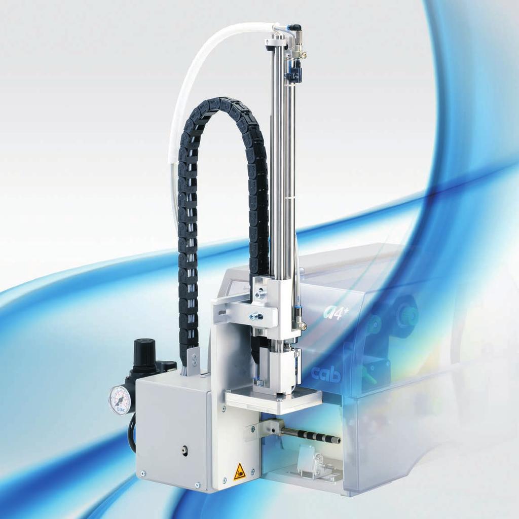
6 6 2 Product Descrpton Functon The Applcator A1000 s an optonal devce to use wth cab prnters of the A+ or A seres for automatcally applyng the prnted label onto the product. The labels are transferred wth a pad, whch moves between the two postons, startng poston and labellng poston, by a compressed-ar drven pneumatc cylnder. In the startng poston, the label s pcked up from the prnter. A sensor at the cylnder sgnals when the pad s n the startng poston. The label s removed from the carrer rbbon drectly at the dspense edge of the prnter. It s sucked on the pad by a vacuum va drllngs at the bottom of the pad. For support, the label s also blown aganst the pad wth an ar current comng from a blow tube. The correct transfer of the label s controlled by a vacuum sensor. Next, the pad s moved down nto the labellng poston. Reachng the labellng poston s confrmed by another sensor (labellng poston sensor). In the labellng poston the label s transferred onto the product. Whle the pad s movng back nto the startng poston, the vacuum sensor checks whether the label has been removed from the pad. The label can be appled wth three dfferent methods : Stamp on The label s pressed drectly onto the product. Blow on The pad moves to a pre-adjusted poston approxmately 10mm away from the product. The label s blown onto the product by an ar stream. Roll on In the startng poston the label s forwarded untl touchng the roller of the roll on pad. At the labellng poston the roller s pressed onto the product. Then the label s appled and rolled on by the movement of the product. 2.2 Important Features The supportng ar and the vacuum as well as the speed of the cylnder are adjustable. That way the applcator can be adapted to dfferent label materals and szes. To avod contamnaton wthn the vacuum channels they are cleaned by ar pressure mpulse at the end of each applcaton. For operaton n a networked system the 15-pn or 25-pn applcator's PLC (programmable logc control) nterface wth potental free nputs and outputs can be used. 2.3 Techncal Data Label transfer method Stamp on Roll on Blow on Label wdth n mm Label heght n mm Cylnder stroke n mm 220 / 300 / 400 Pad stroke below prnter n mm 70 / 150 Compressed ar pressure 0,5 MPa (5 bar) Sound pressure level max. 79 db(a) Product surface flat Product heght varable - fxed - - Product fxed - lnear movement - Table 1 Techncal Data
7 2 Product Descrpton 2.4 Devce Overvew Man pressure manometer 2 Knurled screw for attachng the applcator to the prnter 3 Upper cylnder throttle valve 4 Stopper for the operaton mode "Blow on" 5 Cylnder unt 6 Pneumatc cylnder 7 Lower cylnder throttle valve 8 Pad holder 9 Pad (applcaton specfc) 10 Blow tube for supportng ar Fg. 2 Front vew Knurled screw for attachng the applcator to the prnter 10 Blow tube for supportng ar 11 Vacuum throttle valve 12 Supportng ar throttle valve 13 Pre-dspense key 14 Interface to the prnter 15 Pns 16 Compressed ar connector pn PLC nterface connector pn PLC nterface connector 19 Shutoff valve 20 Servce unt Fg. 3 Rear vew
8 8 2 Product Descrpton Pads Tamp Pads Unversal tamp pad A1021 Standard szes : 70x60, 90x90 Unversal tamp pad A1321 Standard szes : 116x102, 116x152 Fg. 4 Unversal tamp pad A x60 Fg. 5 Unversal tamp pad A x152 Unversal tamp pads (Type A1112 or Type A1312) are avalable n dfferent standard szes. Accordng to the sze of the label the holes may be perced by the customer. For that purpose a percng pn s ncluded n the delvery contents. On request, tamp pads customzed to the label szed are delvered Roll-on Pads Fg. 6 Roll-on pad A1411 bxh Roll-on pads (Type A1411) are only produced on request customzed to the label sze Blow Pads Fg. 7 Blow pad A2021 bxh Blow pads (Type A2111) are only produced on request customzed to the label sze.
9 3 Installaton 3.1 Contents of Delvery 9 1 Applcator 2 Pad (as ordered) 3 Cylnder screw (part of the pad) 4 Percng pn (at unversal tamp pads only) - Documentaton Fg Contents of delvery Notce! Please keep the orgnal packagng n case the applcator must be returned.! Attenton! The devce and prntng materals wll be damaged by mosture and wetness. Set up label prnter wth applcator only n dry locatons protected from splash water. 3.2 Mountng the Applcator to the Prnter Attenton!! Dsconnect the prnter from the power supply before mountng the applcator! Ensure a stable standng of the prnter! Connect the compressed ar only after mountng the applcator to the prnter! Fg. 9 Mountng the applcator 1. Insert the pns (15 / fg. 3) on the back of the applcator (2) nto the holes (3) of the prnter. 2. Press the applcator aganst the prnter. That way the plug of the applcator wll be connected to the perpheral port (4) of the prnter. 3. Fx the applcator (2) wth the screw (1).
10 10 3 Installaton Percng the Unversal Tamp Pad On the bottom of the pads there are holes for suckng and holdng the labels by vacuum. When an unversal tamp pad s delvered these holes are covered by the sldng fol and must be opened accordng to the label sze. For that purpose a percng pn s ncluded n the contents of delvery. 4 2 mm Fg. 10 Percng the unversal tamp pad 1. Place a label (1) to be operated on the bottom sde of the pad (2). Note the poston of the slanted edge (3). 2. Algn the label to the sde edge n such a way that t reaches over the rear edge of the pad by 2 mm. 3. Open all the holes, whch are certanly covered by the label. Open the holes completely by turnng the percng pn (4) nsde the holes. Attenton!! Do not open holes, whch are located less than 1 mm from a label edge. 3.4 Preparng the Applcator for Usng a Tamp Pad Type 1312 The cylnder unt (6) can be mounted on the bracket (1) n two dfferent postons. When the applcator s delvered, the cylnder unt s mounted on the bracket usng the upper threaded hole (4). That poston s sutable for the most pads Fg. 11 Changng the attachment of the cylnder unt For usng an unversal tamp pad type A1312 the fttng of the cylnder unt must be changed : 1. Loosen the screw (3) wth washer (2) and remove the cylnder unt from the bracket (1). 2. Fx the cylnder unt wth screw (3) and washer (2) by usng the lower threaded hole (5).
11 3 Installaton 3.5 Mountng the Pad Fg. 12 Mountng the pad 1. Pull the tube (6) out of the push-n-fttng 2. Insert the pn (5) on the pad (8) nto the hole on the bottom sde of the pad holder (7). 3. Fx the pad (8) wth the screw (1) at the pad holder (7) and make a rough adjustment of the pad to the prnter dspense plate. 4. Insert the vacuum tube (2) an the blowng ar tube nto the approprate push-n-fttngs (3,4) of the pad. 5. Insert the tube (6) nto the approprate push-n-fttng on the cylnder. Attenton!! To avod possble collsons of the pad wth other parts of the prnter-applcator system, please roughly algn the pad n all drectons ( "Mechancal Adjustments") before connectng the applcator to the compressed ar supply! 3.6 Mountng the Stopper Fg. 13 Mountng the stopper When the applcator s delvered, the stopper (1) s mounted on the rods (4). Wth ths stopper the labellng poston for the operaton mode "Blow on" can be adjusted. In the operaton modes "Stamp on" and "Roll on" the stopper s not needed. Operaton modes "Stamp on" and "Roll on" Loosen the screw (3) at the stopper (1). Slde the stopper (1) as far as possble upwards and tghten the screw (3). The stopper must not lmt the pad movement. or Remove the stopper (1) upwards from the rods (4). Operaton mode "Blow on" If necessary, slde the stopper (1) wth the rubber buffer (2) down onto the rods (4). Adjust the stopper (1) ''Adjustng the Stopper''.
12 12 3 Installaton Connectons! Attenton! The pad wll mmedately be moved n the startng poston! Danger of crushng to hand and fngers by the movng pad! Do not reach nto the zone of the movng pad and keep long har, loose clothes, and jewelry dstant. Danger of strkng by the movng rods! Fg. 14 Compressed ar connecton 1. Prepare the prnter connectons to the power supply and to the computer Operator's manual of the prnter. 2. Connect the PLC nterface usng the 15-pn or 25-pn connector "PLC Interface". 3. Close the shutoff valve (3 / lever at the valve s turned across the ar flow drecton). 4. Connect the applcator to the compressed ar supply. The connector (2) for the compressed ar supply s located at the servce unt. The connector s sutable for a 1/4" couplng plug (1). 5. The ar pressure for operatng the applcator s pre-adjusted to 0.5 MPa (5 bar). Check the pressure at the manometer of the servce unt. Correct the adjustment f necessary : - Pull knurled knob (4) up. - Turn knob to tune requred operatng pressure of 5 bar. - Push knob down. 6. Open the shutoff valve. (3 / lever s turned n the ar flow drecton) 7. Swtch on the power supply of the prnter. Notce! In case the pad s outsde the start poston n the moment of swtchng on t wll nterupted the procedure and gve notce an error message on the dsplay of the prnter. If you push the button PAUSE on the prnter s recept the error and the applcator wll move nto the start poston. The Applcator s ready for work.
13 4 Confguraton 13 The tamp applcator can be operated n dfferent ways. Whle the orgnal process stays the same, the operaton mode can be chosen wthn the prnter setup. The most mportant settng s the selecton between the operaton modes "Stamp on", "Blow on" and "Roll on". Addtonally the applcator has dfferent applcaton modes concernng the order of prntng and applyng wthn one labellng cycle. Stamp on Roll on Blow on Prnt/Apply x x x Apply/Prnt x x x Watng poston up Apply/Prnt Watng poston down - - x Table 2 Operaton and applcaton modes Addtonally all operatng modes can be adjusted by settng dfferent tme delays. Notce! For more nformaton about the prnter confguraton and the functon of the keys n the navgator pad Confguraton manual of the prnter (A+ seres) or Operator's manual of the prnter (A seres). De followng descrpton apply to the prnters of the A+ seres. For prnters of the A seres there are margnal dfferences n the key functons. 4.1 Method for Changng the Prnter Setup 1. Press menu key. 2. Select Setup > Machne param. > Applcator. 3. Select and adjust the needed parameters. 4. Return to the "Ready" mode. 4.2 Quck Mode for Settng the Delay Tmes Besde the standard method for the prnter confguraton there s a quck mode to adjust the delay tmes avalable. Notce! The quck mode settngs can be made durng operaton. The changes affect drectly the current prnt job. 1. Press the menu key for at least 2 seconds. The frst delay tme appears on the dsplay. 2. Adjust the delay tme by pressng the ~ key and key. 3. To swtch between the dfferent delay tmes press the } key. 4. To leave the quck setup mode press the key. The selected delay tmes are stored n the prnter.
14 14 4 Confguraton Confguraton Parameters of the Applcator The confguraton parameters of the applcator can be found n the menu Setup > Machne param.. Parameter Meanng Default Applcator Confguraton parameters of the applcator > Mode of oper. Settng the operaton mode Stamp on, Roll on, Blow on Stamp on > Mode of appl. Settng the applcaton mode Prnt-Apply / Apply-Prnt > Watng poston Prnt-Apply: An external start sgnal releases the prnt of a label and followng the applcaton of the label. After a cycle s complete, the pad wthout label wats n the start poston. Apply-Prnt: An extra sgnal starts the prnt of the frst label and the transfer of the label to the pad. The external start sgnal releases the applcaton of the label and followng the prnt and transfer of the next label. After a cycle s complete, the pad wth a label s n the watng poston. only at Mode of oper. Blow on and Mode of appl. Apply-Prnt up : Pad wats n the start poston for the start sgnal down : Pad wats n the labellng poston for the start sgnal > Blow tme only at Mode of oper. Blow on Swtch-on tme (max. 2,5 s) of the blowng ar for the label transfer > Roll-on tme only at Mode of oper. Roll on Dwell tme (max. 5 s) of the pad n the labellng poston > Support delay on > Support del. off Settng the swtch-on delay (max. 2,5 s) for the supportng ar between prnt start and swtchng on the supportng ar. The delay prevents swrlng at the front of the label and, consequently, avods faults when the label s beng pcked up from the prnter. Settng the swtch-off delay (max. 2,5 s) for the supportng ar between the end of label forwardng and swtchng on the supportng ar. The delay can be useful to separate the rear edge of the label from the carrer to avod errors and to mprove the accuracy of label postonng > Delay tme Delay (max. 2,5 s) between start sgnal and the start of an labellng cycle. Allows e.g. the use of product sensors at conveyors. > Lock tme All start sgnals comng n followng the frst start sgnal are gnored when they arrve wthn the lock tme. > Peel poston Shft the poston of the dspensed label relatvely to the dspense edge. In the software an extra peel offset value s avalable. The offset values from Peel poston and from software are added together for executon. "Settng the Peel Poston". > Vacuum control Settng the label transfer check from prnter to pad and from pad to product by the vacuum sensor Prnt- Apply up 0 ms 0 ms 0 ms 270 ms 0 ms 0 ms 0,0 mm On Table 3 Applcator parameters
15 5 Adjustments 5.1 Mechancal Adjustments Perform the mechancal adjustments n two steps : Roughly algn the pad n all drectons to avod collsons of the pad wth other parts when swtchng on the compressed ar. Perform the fne adjustment wth compressed ar swtched on to optmze the labellng process Algnng the Pad Fg. 15 Algnng the pad Adjustment n prnt drecton 1. Loosen screw (3). 2. Shft the cylnder unt ncludng the pad (4) nsde the elongated hole n such a way, that the dstance between the pad and the dspense edge s about 2 mm. 3. Tghten screw (3). Heght adjustment 1. Loosen screw (1). 2. Shft the cylnder unt ncludng the pad (4) nsde the elongated hole n such a way, that the lower rear edge of the pad s located about 1 mm below the dspense edge of the prnter. 3. Tghten screw (1). Sde adjustment 1. Loosen screw (2). 2. Shft the cylnder unt ncludng the pad (4) nsde the elongated hole n such a way, that the dspensed label s algned centrally to the pad respectvely to the open holes n an unversal pad. 3. Tghten screw (2). Notce! Check the adjustments wth compressed ar swtched on.
16 16 5 Adjustments Adjustng the Parallelsm between Pad and Dspense Edge 1. Loosen screw (1). 2. Adjust the parallelsm between the rear edge of the pad (2) and the dspense edge (3) by turnng the pad. 3. Tghten screw (1) Fg. 16 Adjustment of parallelsm Openng the Holes on the Blow Tube The blow tube (1) has holes for the supportng ar n regular dstances of 15 mm. When the applcator s delvered only the two nner holes are open. The other holes are closed by plastc rngs (3). To adjust the supportng ar to the label wdth, the plastc rngs (2) can be removed from the holes. Open all holes, whch affect certanly the area of the label Fg. 17 Openng the holes on the blow tube Algnng the Blow Tube Fg. 18 Algnment of the blow tube The blow tube (2) for the supportng ar can be rotated around ts axs. That way the drecton of the supportng ar can be optmzed. 1. Loosen screw (1). 2. Turn the blow tube (2) n that drecton, that the ar current supports the suckng of the label by the pad. For small labels drect the ar current to the dspense edge (3) of the prnter (settng 3 or 4 at the scale). For larger labels drect the ar current away from the dspense edge (3) (settng 1). 3. Tghten screw (1).
17 5 Adjustments Adjustng the Stopper Fg. 19 Adjustng the stopper Notce! For operaton mode "Blow on" only! Attenton!! Swtch off the prnter and close the shutoff valve for the compressed ar at the servce unt! 1. Place a product sample (7) at the labellng pont. 2. Pull the tubes out of the push-n-fttngs (1,5). 3. Loosen the screw (3) n the stopper (2). 4. Move the pad manually n the requred labellng poston. The dstance between the blow pad (6) n the labellng poston and the product surface (7) must not exceed 10 mm. 5. Move the stopper (2) aganst the gude block (4) and tghten the screw (3). 6. Insert the tubes nto the approprate push-n-fttngs (1,5). 7. Open the shutoff valve and swtch on the prnter.
18 18 5 Justagen Adjustments Pneumatc Adjustments Control Valves Fg. 20 Control valves For adjustments of specal applcator functons t's possble to swtch the control valves drect by hand.. Loosen screws (1) and remove cover (2). It's possble to ntate the valves va ntegrated swtches. 3-way valve (3) to control the lft cylnder If the prnter s swtched on the valve wll controlled by electroncs and the tamp wll hold n the upper end poston (take over poston). If the valve swtched the tamp wll move n the labelng poston. In normal operaton the movement back n the upper end poston wll start by a sgnal from labelng sensor. Notce! The swtchng by hand of ths valve has only a result n case of a swtched off prnter. When you swtch the valve by hand over swtch (6) the tamp wll move down. When you swtch the valve by hand over swtch (6) the tamp wll move up. Double 2-way valve (4) for blow ar In the operaton mode "blow" the label wll blow up to the product. n the operaton mode "tamp" and "roll" wll swtch on the blow ar for a short tme n the back movement. to clear the tamp. For all descrbed Functon both valves wll controlled parallel. In case of swtchng by hand va swtch 8 or 9 wll swtch on the blow ar only over one of the both nternal valves. Double 2-way valve (5) for vacuum / support ar The both nternal valves swtch on the vacuum generator to create a vacuum on the tamp and ntended of ths to swtch on the support ar over the support ar tube for a perfect label take over procedure.. Wth swtch 10 you can swtch the vacuum and wth swtch 11 you can swtch the support ar.
19 5 Adjustments Adjustng the Pad Movement Speed Fg. 21 Throttle valves on the cylnder The speed of the pad movement can be regulated va two throttle valves (1, 3). Adjust the pad movement speed as necessary. To ncrease the downward speed turn counterclockwse the screw (4) at the lower valve (3). To ncrease the upward speed turn counterclockwse the screw (2) at the upper valve (1). Notce! The applcaton pressure of the pad s manly dependent on the downward speed of the pad. In order to reduce the applcaton pressure turn clockwse the screw (4).! Attenton! The tme for the downward movement of the pad may not exceed 2 seconds Otherwse the error message "Lower poston" wll appear.
20 20 5 Adjustments Adjustng Vacuum and Supportng Ar 1 2 Fg. 22 Throttle valves on the manfold Adjustng the supportng ar Wth the valve (1) the supportng ar to blow the label aganst the pad can be adjusted. Adjust the supportng ar n such a way, that t wll be blown aganst the label wthout swrlng. To ncrease the supportng ar turn counterclockwse the screw at the valve (1). If necessary adjust the drecton of the ar current ''Algnng the Blow Tube''. Adjustng the vacuum Wth the valve (2) the vacuum to suck the label onto the pad can be adjusted. Adjust the vacuum n such a way, that the label s properly sucked by the pad. To ncrease the vacuum turn counterclockwse the screw at the valve (2). Notce! Wth the vacuum settng the fnal poston of the label on the pad can be adjusted. If the vacuum s too hgh the label feedng may early be stopped Opton Pressure Reducton Valve The pressure reducton valve wll used n case of labellng pressure-senstve products or generally safety aspects to reduce the pressure nto the cylnder n Z-drecton. The settng standard value s 2,5 bar. Fg. 23 Pressure reducton valve Cylnder Z
21 6 Operaton 6.1 Loadng Labels and Transfer Rbbon Fg. 24 Label and transfer rbbon feed path Insert transfer rbbon (1). Insert labels (2) for operaton n peel-off mode Detaled nformaton Operator's manual of the prnter.! Attenton! Swvel the lockng system (4) aganst the rewnd assst roller (3). Otherwse the pad (5) would collde wth the lockng system (4) durng operaton. 6.2 Actvaton of Peel-off Mode Notce! For labellng operaton actvate the peel-off mode n the software. For drect programmng use the P command Programmng manual. 6.3 Settng the Peel Poston To optmze the transfer of the labels from the prnter to the pad there two dfferent parameters are avalable for adjustng the peel poston. Attenton!! Frst adjust the parameter "Peel Poston" n the prnter confguraton. Followng adjust the addtonal peel-off offset n the software. It s very mportant to follow that procedure for a certan start after label loadng and for the re-start after error treatment. Parameter "Peel Poston" n the prnter confguraton Check the basc settng n the prnter setup. Perform labellng cycles by alternately pressng the feed key and the pre-dspense key "Test Mode Usng the Pre-dspense Key wthout Prnt Job". Adjust the "Peel Poston" n such a way, that the blank labels are peeled-off completely from the lner "Confguraton Parameters of the Applcator". Peel-off offset n the software Check the settng n the software. Perform labellng cycles by repeatedly pressng the the pre-dspense key "Test Mode Usng the Pre-dspense Key wth Prnt Job". Adjust the peel-off offset n such a way, that the prnted labels are peeled-off completely from the lner Programmng manual or software documentaton.
22 22 6 Operaton Test Mode Usng the Pre-dspense Key wthout Prnt Job 1 Fg. 25 Pre-dspense key The whole labellng process can be smulated wthout the need of a prnt job or a connecton to a computer by alternately pressng the feed key and the pre-dspense key (1) : Press the feed key. A blank label s fed. The vacuum at the pad as well as the supportng ar (blow tube) are swtched on. After the label has been pcked up by the pad, the supportng ar s swtched off. Press the pre-dspense key (1). The pad s moved to the labellng poston. A sensor sgnals when the labellng poston s reached. The vacuum s swtched off and the label s placed onto the product. Then, the pad s moved back nto the startng poston. Notce! Please use that test mode to adjust the parameter "Peel poston" n the prnter confguraton. 6.5 Test Mode Usng the Pre-dspense Key wth Prnt Job That method allows to check labellng process wth the real prnt data usng the pre-dspense key (1). Send a prnt job. The test mode s executed n two half cycles : Press the pre-dspense key (1). Half cycle 1 A label s prnted. The vacuum at the pad as well as the supportng ar (blow tube) are swtched on. After the label has been pcked up by the pad, the supportng ar s swtched off. Press the pre-dspense-key (1) agan. Half cycle 2 The pad s moved to the labellng poston. A sensor sgnals when the labellng poston s reached. The vacuum s swtched off and the label s placed onto the product. Then, the pad s moved back nto the startng poston. If the label s manually removed from the pad after the frst half cycle, the half cycle 1 wll be repeated when the predspense key s pressed agan. Notce! Please use that test mode to adjust the peel-off offset n the software.
23 6 Operaton 6.6 Standard Operaton Check all external connectons. Load the materal. Ensure that the lockng system s locked "Loadng Labels and Transfer Rbbon". Open the shutoff valve. Attenton!! Ensure that the pad s not covered by a label when swtchng on the prnter-applcator system. Otherwse the vacuum sensor may be calbrated faultly. 23 X X Swtch on the prnter. Notce! In case the pad s outsde the start poston n the moment of swtchng on t wll nterupted the procedure and gve notce an error message on the dsplay of the prnter. If you push the button PAUSE on the prnter s recept the error and the applcator wll move nto the start poston. The Applcator s ready for work. Press the feed key at the prnter. A synchronzaton feed s released. The processed labels have to be removed manually. After a few seconds the prnter carres out a short backfeed to poston the front edge of the next label at the prntng lne. Notce! Ths synchronzng also has to be carred out when the prnt job has been nterrupted wth the cancel key. Synchronzng s not necessary when the prnthead was not lfted between prnt jobs. Ths also apples f the prnter was powered off between prnt jobs. Start a prnt job Start the labellng process va PLC nterface. Error messages durng labellng process are shown n the dsplay of the prnter "Error Messages". 7 PLC Interface Pn 1 Pn 9 Pn 1 Pn Pn 8 Pn 15 Pn 13 Pn 25 Fg. 26 PLC nterface connectors For use n a networked system the applcator s equpped wth a PLC nterface to start and nterrupt the labellng process. It also passes on state nformaton as well as error messages of the applcator to the system control. The nterface s placed at the backsde of the applcator and has a 15 pn (1) as well as a 25 pn (2) SUB-D connector. Notce! The 15 pn connector has the dentcal pn assgnment as the PLC nterface of the cab Hermes applcators.
24 24 7 PLC Interface Pn Assgnment and Sgnal Descrpton Notce! The numbers n the brackets apply to the 15 pn connector! Pn 25 pn Pn 15 pn Sgnal A1000 Sgnal Hermes Appl. Descrpton Actvaton / Actve state 1 1 E0.1 (+) XSTART Start sgnal for the cyclc labellng process. Swtch on +24V between Pn 1 and Pn 14 (9) 2 2 E0.2 (+) XSTOP Stop sgnal (external error) The followng functons are released : the prnt of a label and ts pckng-up by the pad wll be fnshed the labellng process s nterrupted the pad returns nto the startng poston all followng start sgnals are gnored f actvated durng the labellng phase, the dsplay wll show the message 'Host stop/ error'. (no message durng prnt process) 3 3 E0.3 (+) XDREE Prnt frst label for applcaton mode "Apply/Prnt" only : releases the prnt of the frst label and ts pckng-up by the pad 4 4 A0.1 XDNB Prnter not ready Error message of the prnter. The error type s shown on the dsplay. After error correcton, the prnt of the last label wll be repeated. 5 5 A0.2 XEDG No exstng prnt job. State message. There s no prnt job currently avalable. 6 6 A0.3 XSAA General error message General error message of both, prnter and applcator. Ths message s shown when one of the two errors ether XDNB or XETF occurs. Important n case that only one error sgnal of the applcator can be analyzed from the system control. 7 7 A0.4 XSOE Pad n startng poston The pad s n the startng poston where t pcks up the label from the prnter. 8 8 GND GND Ground (0V) Attenton! Do not connect Pn 8 wth the ground of the PLC. Otherwse the galvanc separaton would be lost. 9 A0.5 Specal sgnal x command (bt 0) f Bt 0 s set : s controlled by the X command n the drect programmng for detaled descrpton of the X command Programmng manual 10 not connected 11 E0.5 (-) External reset (reverse lne) Swtch on +24V between Pn 2 and Pn 15 (10) Swtch on +24V between Pn 3 and Pn 16 (11) Contact between Pn 4 and Pn 19 (14) s open Contact between Pn 5 and Pn 19 (14) s open Contact between Pn 6 and Pn 19 (14) s open Contact between Pn 7 and Pn 19 (14) s open Contact between Pn 9 and Pn 19 s closed
25 7 PLC Interface 25 Pn 25 pn Pn 15 pn Sgnal A1000 Sgnal Hermes Appl. Descrpton 12 do not use 13 do not use 14 9 E0.1 (-) XSTARTR Start sgnal (reverse lne) Actvaton / Actve state E0.2 (-) XSTOPR Stop sgnal (reverse lne) E0.3 (-) XDREER Prnt frst label (reverse lne) A0.7 XSUE Pad n labellng poston The pad s n the poston where the label s appled to the product A0.8 XETF Applcator fault Error message of the applcator The error type s shown on the dsplay. After error correcton, the prnt of the last label cannot be repeated COM RÜL Lne wth common potental for all output sgnals, may be connected wth 24V or GND V (Out) 24P Operatng voltage +24V, S T 100mA provded by the applcator. Example : To generate the start sgnal by a foot swtch. Attenton! Do not connect an external voltage to Pn 20 (15)! 21 A0.9 Specal sgnal x command (bt 0) s controlled by the X command n the drect programmng for detaled descrpton of the X command Programmng manual 22 not connected 23 E0.5 (+) XRST External Reset Error state n the prnter wll be qut, the applcator wll be reset (comparable to pressng the pause key) 24 do not use 25 A0.10 /XSOE Pad n startng poston (nverted) The pad s n the startng poston where t pcks up the label from the prnter. Contact between Pn 7 (12) and Pn 19 (14) s open Contact between Pn 18 (13) and Pn 19 (14) s open f Bt 3 s set : Contact between Pn 21 and Pn 19 s closed Swtch on +24V between Pn 23 and Pn 11 Contact between Pn 25 and Pn 19 s closed Table 4 PLC sgnals
26 26 7 PLC Interface Crcut Dagrams of Inputs and Outputs Notce! The numbers n the brackets apply to the 15 pn connector! Inputs The nputs are optocouplers wth a current lmtng resstor of 2,4 kω n the nput crcut for an operatng voltage of 24V. For each sgnal [IN (+)] there s a separate reverse lne [IN (-)] at the plug connector. Outputs All outputs are realzed wth sold state relays. The outputs are connected among one another one-sded. The common lne s lead to the plug connector as COM sgnal. The swtch functon of the outputs s to open or close the contact between the common lne COM and the respectve output. Electrcal requrements : U max = ± 42 V, I max = 100 ma Resstance of the closed contact : R <= 25 Ω E0.1 (+) Pn 1 E0.1 (-) Pn 14 (9) E0.2 (+) Pn 2 E0.2 (-) Pn 15 (10) E0.3 (+) Pn 3 E0.3 (-) Pn 16 (11) E0.5 (+) Pn 23 E0.5 (-) Pn 11 Pn 4 A0.1 Pn 5 A0.2 Pn 6 A0.3 Pn 7 A0.4 Pn 9 A0.5 Pn 17 (12) A0.7 Pn 18 (13) A0.8 Pn 21 A0.9 Pn 25 A0.10 Pn 19 (14) COM Fg. 27 Crcut of the nputs (left) and outputs (rght) 7.3 Examples for External Crcuts Notce! The numbers n the brackets apply to the 15 pn connector! Pn 20 (15) 24 V Pn 1 Pn 14 (9) GND Pn 8 Sgnal swtch Applcator Fg. 28 Optcal sensor wth pnp output to create the start sgnal
27 7 PLC Interface 27 brown Pn 20 (15) 24 V brown Pn 20 (15) 24 V whte/ black* Pn 1 Pn 1 Pn 14 (9) whte/ black* Pn 14 (9) Sensor wth pnp output blue Pn 8 Applcator GND Sensor wth npn output blue Pn 8 Applcator GND * depend of used sensor Fg. 29 Optcal sensor wth pnp-output (left) Optcal sensor wth npn-output (rght) to create the start sgna Pn 20 (15) 24 V Pn 1 Pn 14 (9) Pn 5 Pn 19 (14) Pn 8 Applcator GND Fg. 30 Example for automatc creaton of a start sgnal after recevng a prnt job (for jobs wth label amount = 1 only) Pn 20 (15) 24 V Pn 3 Pn 16 (11) Pn 5 Pn 19 (14) Pn 8 GND Pn 1 Pn 14 (9) Applcator Fg. 31 Example for automatc creaton of the sgnal "Prnt frst label" after recevng a prnt job and release of the cyclc labellng by a trgger swtch n the applcaton mode "Apply/Prnt"! Attenton! When usng the examples of the fgures 30 or 31 and connectng addtonal output sgnals to a PLC, the galvanc separaton on the applcator sde wll be lost! Realze the galvanc separaton on the PLC sde!
28 28 8 Error Messages Error Messages of the Prnter For detaled nformaton about prnter errors (e.g. 'Paper out', 'Rbbon out', etc.) Operator's manual of the prnter Error treatment : Clear the error results Press the feed key to synchronze the label feed, remove the peeled labels manually Press the pause key to qut the error state. After error correcton, the prnt of the label causng the error wll be repeated. 8.2 Error Messages of the Applcator The followng table contans an overvew of error messages and ther possble causes. It also suggests methods to resolve the problem : Error Message Possble Cause Soluton Ar pressure Compressed ar s swtched off Check the shutoff valve ns. Host stop/ error Labellng process has been Interrupted Label the product manually f necessary by an stop sgnal va PLC nterface Label not depos. Label has not been placed onto the Label the product manually f possble product; after the pad has moved back the label stll stcks on the pad Lower poston Pad has not reached the labellng poston wthn 2s after the movement of the pad was started Check the pneumatc adjustments (esp. the lower throttle valve of the cylnder); Check the applcator for heavness of ts mechancs; Check the labellng poston sensor (servce); Label the product manually Refl. sensor blk. There has been no change of the swtch state at the upper sensor at the cylnder between the start of the labellng process and the sgnal from the labellng poston sensor Check the sensor (servce) Upper poston Vac. plate empty Table 5 Pad has not reached the startng poston wthn 2s after the pad has left the labellng poston; or pad has left the startng poston unauthorzed Label has not been pcked up properly by the pad; or label fell off the pad before t could be placed onto the product Error messages of the applcator Check the pneumatc adjustments (esp. the upper throttle valve of the cylnder); Label the product manually If possble, place the 'lost' label onto the product manually; Otherwse stop prnt job and start agan wth adapted parameters (e.g. count) If the error recurs check the pad algnment, the adjustment of vacuum and supportng ar and the settng of the peel poston Error treatment : Clear the error results Press the pause key to qut the error state. Attenton!! The pad wll mmedately be moved n the startng poston! Danger of crushng to hand and fngers by the movng pad! Do not reach nto the zone of the movng pad and keep long har, loose clothes, and jewelry dstant. After error correcton, the prnt of the label causng the error cannot be repeated wthout re-start of the prnt job. In the applcaton mode "Apply/Prnt" send the sgnal "Prnt frst label" or press the pre-dspense key before startng the cyclc operaton.
29 9 Functon of the LED n the electroncs of the applcator 29 LED3 LED4 LED5 LED6 LED7 LED1 Fg. 32 LED on the PCB applcator control LED-No. Color Functon actve value 1 green VAK Label on tamp ON 3 green PLC-Sgnal XSTART ON 4 green PLC-Sgnal XSTOP ON 5 green PLC-Sgnal XDREE ON 6 green PLC-Sgnal XRST ON 7 green not mplement Table 6 LED on the PCB applcator control
30 30 10 Declaraton Declaraton of Incorporaton cab Produkttechnk GmbH & Co KG Wlhelm-Schckard-Str. 14 D Karlsruhe Deutschland Declaraton of Incorporaton We declare herewth that the followng partly completed machnery as a result of desgn, constructon and the verson put n crculaton comples wth the essental requrements of the Drectve 2006/42/EC on machnery : Annex I, Artcle 1.1.2, 1.1.3, 1.1.5, 1.1.6, 1.2.1, 1.3.2, 1.5.2, 1.5.8, 1.6.3, 1.7 In the event of any alteraton whch has not been approved by us beng made to any devce as desgnated below, ths statement shall thereby be made nvald. Devce: Type: Applcator A1000 Appled EU Regulatons and Norms: Drectve 2006/42/EC on machnery EN ISO 12100:2010 EN ISO :2015 EN :2006 +A11:2009+A12:2011+A1:2010+A2:2013 Person authorsed to comple the techncal fle : Erwn Fascher Am Unterwege 18/ Sömmerda Sgned for, and on behalf of the Manufacturer : Sömmerda, cab Produkttechnk Sömmerda Gesellschaft für Computerund Automatonsbaustene mbh Sömmerda Erwn Fascher Managng Drector The product must not be put nto servce untl the fnal machnery nto whch t s to be ncorporated has been declared n conformty wth the provsons of the Drectve on machnery The documents accordng annex VII part B from the ncomplete machnery are created and wll commt to state agences on request n electronc knds.
31 10 Declaraton 10.2 EU Declaraton of Conformty 31 cab Produkttechnk GmbH & Co KG Wlhelm-Schckard-Str. 14 D Karlsruhe Deutschland EU Declaraton of Conformty We declare herewth that as a result of the manner n whch the devce desgnated below was desgned, the type of constructon and the devces whch, as a result have been brought on to the general market comply wth the relevant fundamental regulatons of the EU Rules for Safety and Health. In the event of any alteraton whch has not been approved by us beng made to any devce as desgnated below, ths statement shall thereby be made nvald. Devce: Type: Applcator A1000 Appled EU Regulatons and Norms: Drectve 2014/30/EU relatng to electromagnetc compatblty EN 55032:2012 EN 55024:2010 EN :2005 Drectve 2011/65/EU on the restrcton of the use of certan EN 50581:2012 hazardous substances n electrcal and electronc equpment Sgned for, and on behalf of the Manufacturer : Sömmerda, cab Produkttechnk Sömmerda Gesellschaft für Computerund Automatonsbaustene mbh Sömmerda Erwn Fascher Managng Drector
32 32 11 Index 32 A Ar pressure...6, 12 Ar pressure ns...28 Applcator fault...25, 28 Apply/Prnt...13, 14, 28 B Blowng ar... 11, 14 Blow on... 6, 7, 11, 13, 14, 17 Blow pad...8, 17 Blow tme...14 Blow tube...6, 7, 16 C Cancel key (prnter)...23 Compressed ar connector...7, 12 Confguraton...13, 14 Conformty EU Declaraton of...30, 31 Connectons...12 Contents of delvery...9 Control valves...18 Cylnder unt...7, 10, 15 D Delay tme (start)...14 Delay tmes...13, 14 Dspense edge...6, 14, 15, 16 E EU Declaraton of Conformty... 30, 31 Envronment...4, 5 Error messages...23, 28 F Feed key (prnter)...21, 22, 23, 28 G General error message...24 H Heght adjustment...15 Host stop / error...24, 28 I Important nformaton...4 Intended use...4 L Labellng poston... 6, 11, 14, 17, 28 Labellng poston sensor...6, 22, 28 Label not depos...28 LED...29 Lock tme...14 Lower poston...19, 28 M Manfold...20 Manometer...7, 12 Menu key (prnter)...13 N No exstng prnt job...24 O Operatng voltage...25 Operaton mode...6, 13, 14 Operaton voltage...29 P Pad n labellng poston...25 Pad n startng poston...24, 25 Pause key (prnter)...25, 28 Peel-off mode...21 Peel poston...14, 21, 22, 28 Perpheral port...9 Percng pn...8, 9, 10 PLC nterface Pn assgnment...24 Sgnals...24 Pneumatc cylnder...7 Pre-dspense key...7, 21, 22, 28 Prnt/Apply...13, 14 Prnter not ready...24 Prnt frst label...24, 25, 28 Q Quck mode for settng delay tmes R Refl. sensor blk...28 Reset...25 Roll-on pad...8 Roll-on tme...14 Roll on... 6, 11, 13, 14 S Safety nstructons...4 Safety markng...5 Servce unt...7, 12 Servce work...5 Shutoff valve...7, 12, 23, 28 Sde adjustment...15 Sldng fol...10 Speed of pad movement...19 Stamp on... 6, 11, 13, 14 Startng poston...6, 12, 14, 28 Start sgnal...24, 25 Stopper... 7, 11, 17 Stop sgnal...24, 25 Supportng ar...6, 7, 14, 16, 20, 28 swtch-off delay...14 swtch-on delay...14 Synchronzng...23, 28 T Tamp pad...8 Test mode...22 Throttle valve...7, 19, 20, 28 U Unversal tamp pad...8, 10 Upper poston...28 V Vac. plate empty...28 Vacuum...6, 7, 10, 20, 28 Vacuum control...14 Vacuum sensor...6, 14, 23 W Watng poston...13, 14 Warnng stckers...5
Service Manual 5414/5416. Vacuum-Belt Applicator. Made in Germany
 Servce Manual Vacuum-Belt Applcator 5414/5416 Made n Germany 2 Servce Manual 2 for the followng products Famly Vacuum-Belt Applcator Type 5414L 5414R 5416L 5416R Edton: 04/2018 - Part No. 9003095 Copyrght
Operator's Manual. PCB Separator MAESTRO 4S
 Operator's Manual PCB Separator MAESTRO 4S 2 Operator's Manual - Translaton of the Orgnal Verson for the followng products Descrpton PCB Separator Type MAESTRO 4S Edton: 10/2017 Part No.: 9009613 Copyrght
Strain Gauge Measuring Amplifier BA 660
 Stran Gauge Measurng Amplfer BA 660 Orgnal of the Manual BA660 / IP20 BA660 / IP66 Table of Contents 1. Safety precautons...2 1.1. Feld of applcaton...2 1.2. Installaton...2 1.3. Mantenance...2 2. Functon...2
Parking barrier Parc 200 / Parc 200 speed
 GB Operatng nstructons Last updated: 01.2014 Parkng barrer Parc 200 / Parc 200 speed 1. Meanng of symbols 2. Table of contents Advce Cauton! Danger of personal njury! The followng safety advce must be
Customer witness testing guide
 Customer wtness testng gude Ths gude s amed at explanng why we need to wtness test equpment whch s beng connected to our network, what we actually do when we complete ths testng, and what you can do to
VRT014 User s guide V0.8. Address: Saltoniškių g. 10c, Vilnius LT-08105, Phone: (370-5) , Fax: (370-5) ,
 , Fax: (370-5) ,") VRT014 User s gude V0.8 Thank you for purchasng our product. We hope ths user-frendly devce wll be helpful n realsng your deas and brngng comfort to your lfe. Please take few mnutes to read ths manual
VRT014 User s gude V0.8 Thank you for purchasng our product. We hope ths user-frendly devce wll be helpful n realsng your deas and brngng comfort to your lfe. Please take few mnutes to read ths manual
Pneumatic Power Bench Assembly
 Pneumatc Power Bench Assembly 58338-1 Instructon Sheet 408-9393 09 AUG 11 Fgure 1 1. INTRODUCTION Pneumatc Power Bench Assembly 58338-1 s a pneumatc power unt desgned to accept a varety of nterchangeable
Product Information. Jaw quick-change system BSWS-PGZN-plus
 Product Informaton BSWS-PGZN-plus BSWS-PGZN-plus Productve. Flexble. Cost-effectve. BSWS jaw quck-change system The BSWS jaw quck-change system allows top jaws to be changed on the grpper manually and
INSTRUCTION MANUAL BENCH LATHE
 WLLOUGHBY COMMUNTY MEN'S SHED mens 296C Salors Bay Road, l _ L^ NORTHBRDGE N.S.W 2063 The Wlkmghby Communty" NSTRUCTON MANUAL BENCH LATHE Before usng be sure to read ths manual carefully -C6- Safety nstructons
Insertion/Extraction Tool and Replacement Tip Kits [ ]
![Insertion/Extraction Tool and Replacement Tip Kits [ ]](/thumbs/84/89088006.jpg "Insertion/Extraction Tool and Replacement Tip Kits [ ]") Inserton/Extracton Tool 91285-1 and Replacement Tp Kts 543382-[ ] Instructon Sheet 408-9404 19 JUN 12 PROPER USE GUIDELINES Cumulatve Trauma Dsorders can result from the prolonged use of manually powered
Inserton/Extracton Tool 91285-1 and Replacement Tp Kts 543382-[ ] Instructon Sheet 408-9404 19 JUN 12 PROPER USE GUIDELINES Cumulatve Trauma Dsorders can result from the prolonged use of manually powered
Locator Pin Indexing Pin. Wire Size Marking CAUTION NOTE TOOLING ASSISTANCE CENTER PRODUCT INFORMATION
 ROTA-CRIMP* Crmpng Tool Instructon Sheet 408-2681 68321-1 13 APR 12 Statonary De (Nest) Anvl De Hold-Down Devce and Contact Locator Front of Tool Locator Pn Indexng Pn Wre Sze Markng The hold-down devce
PRO- CRIMPER* III Hand Crimping
 PRO- CRIMPER* III Hand Crmpng Instructon Sheet Tool Assembly 91338-1 408-8377 wth De Assembly 91338-2 22 JUL 09 PROPER USE GUIDELINES Cumulatve Trauma Dsorders can result from the prolonged use of manually
Instructions for Use. PetChatz.com. PetChatz.com
 Instructons for Use PetChatz.com PetChatz.com POWER ON/OFF LED PET-SAFE MICROPHONE SOUND DETECTOR MANUAL TREAT RELEASE LOW TREAT LED LOW-LIGHT HD CAMERA for hgh-qualty vdeo MOTION DETECTION FULL-COLOR
PRO- CRIMPER* III Hand Crimping
 PRO- CRIMPER* III Hand Crmpng Instructon Sheet Tool 58448-2 408-9357 Wth De 58448-3 10 Mar 11 PROPER USE GUIDELINES Cumulatve Trauma Dsorders can result from the prolonged use of manually powered hand
PRO- CRIMPER III Hand Crimping Tool Assembly DESCRIPTION (Figures 1 and 2)
") PRO- CRIMPER* III Hand Crmpng Instructon Sheet Tool Assembly 58495-1 408-9819 Wth De Assembly 58495-2 22 JUL 09 PROPER USE GUIDELINES Cumulatve Trauma Dsorders can result from the prolonged use of manually
PRO- CRIMPER* III Hand Crmpng Instructon Sheet Tool Assembly 58495-1 408-9819 Wth De Assembly 58495-2 22 JUL 09 PROPER USE GUIDELINES Cumulatve Trauma Dsorders can result from the prolonged use of manually
PRO-CRIMPER* III Hand Crimping Tool Assembly with Die AssemblY
 PRO-CRIMPER* III Hand Crmpng Tool Assembly 90758-1 wth De AssemblY 90758-2 Instructon Sheet 408-9938 01 NOV 11 PROPER USE GUIDELINES Cumulatve Trauma Dsorders can result from the prolonged use of manually
onlinecomponents.com
 PRO- CRIMPER* III Hand Crmpng Instructon Sheet Tool Assembly 58535-1 wth 408-4021 De Assembly 58535-2 29 JUL 09 PROPER USE GUIDELINES Cumulatve Trauma Dsorders can result from the prolonged use of manually
SPeCtra X-XL. Section 4 Troubleshooting. read the safety information chapter before working on the machines.
 4 SPeCtra X-XL en Secton 4 Troubleshootng Document Number: TD 103 421/A Order Number: 1H 328 259 read the safety nformaton chapter before workng on the machnes. Change log Date Changes Author No. ID 2011-10-19
Instruction Sheet AMPMODU* MTE CONNECTORS Mar 11 Rev A
 Instructon Sheet AMPMODU* MTE CONNECTORS 408-6919 10 Mar 11 PROPER USE GUIDELINES Cumulatve Trauma Dsorders can result from the prolonged use of manually powered hand tools. Hand tools are ntended for
Product Information. Universal gripper JGZ
 Product Informaton Unversal grpper JGZ JGZ Unversal grpper Loadable. Relable. Compact. JGZ unversal grpper Unversal 3-fnger centrc grpper of the compact class wth T-slot gudance and best cost-performance
PRO- CRIMPER* III Hand
 PRO- CRIMPER* III Hand Instructon Sheet Crmpng Tool Assembly 90759-1 408-9962 wth De Assembly 90759-2 03 MAY 11 PROPER USE GUIDELINES Cumulatve Trauma Dsorders can result from the prolonged use of manually
PRO- CRIMPER* III Hand Crimping
 PRO- CRIMPER* III Hand Crmpng Instructon Sheet Tool Assembly 58641-1 wth 408-4379 De Assembly 58641-2 18 JUN 09 PROPER USE GUIDELINES Cumulatve Trauma Dsorders can result from the prolonged use of manually
PRO- CRIMPER III Hand Crimping Tool Assembly INSTALLATION AND REMOVAL OF DIE SET AND LOCATOR ASSEMBLY (Figure 2)
") PRO- CRIMPER* III Hand Crmpng Instructon Sheet Tool Assembly 90547-1 wth 408-9884 De Assembly 90547-2 02 NOV 09 PROPER USE GUIDELINES Cumulatve Trauma Dsorders can result from the prolonged use of manually
PRO- CRIMPER* III Hand Crmpng Instructon Sheet Tool Assembly 90547-1 wth 408-9884 De Assembly 90547-2 02 NOV 09 PROPER USE GUIDELINES Cumulatve Trauma Dsorders can result from the prolonged use of manually
AFV-P 2U/4U. AC + DC Power Solutions. series. Transient Generation for Disturbance Tests. only. High Performance Programmable AC Power Source
 AFV-P seres Hgh Performance Programmable AC Power Source only 2U/4U Intutve Touch Screen HMI Output Frequency up to 15-1000Hz Power Lne Smulatons: Step & Ramp Features Fast Response Tme: 300μs AC Source
PRO- CRIMPER* III Hand
 PRO- CRIMPER* III Hand Instructon Sheet Crmpng Tool Assembly 58529-1 408-9999 wth De Assembly 58529-2 11 AUG 14 PROPER USE GUIDELINES Cumulatve Trauma Dsorders can result from the prolonged use of manually
PRO-CRIMPER* III Hand Tool Assembly with Die Assembly
 PRO-CRIMPER* III Hand Tool Assembly 2063778-1 wth De Assembly 2063778-2 Instructon Sheet 408-10290 02 FEB 12 PROPER USE GUIDELINES Cumulatve Trauma Dsorders can result from the prolonged use of manually
PRO-CRIMPER* III Hand Crimping Tool Assembly with Die Assembly
 PRO-CRIMPER* III Hand Crmpng Tool Assembly 90548-1 wth De Assembly 90548-2 Instructon Sheet 408-9885 02 NOV 12 PROPER USE GUIDELINES Cumulatve Trauma Dsorders can result from the prolonged use of manually
RC Filters TEP Related Topics Principle Equipment
 RC Flters TEP Related Topcs Hgh-pass, low-pass, Wen-Robnson brdge, parallel-t flters, dfferentatng network, ntegratng network, step response, square wave, transfer functon. Prncple Resstor-Capactor (RC)
Product Information. Long-stroke gripper EGA
 Product Informaton EGA EGA Flexble. Modular. Robust. EGA long-stroke grpper Electrc 2-fnger parallel grpper wth lghtweght profle ral gude and adaptable servo- motor Feld of applcaton Optmal standard soluton
PRO- CRIMPER* III Hand
 PRO- CRIMPER* III Hand Instructon Sheet Crmpng Tool Assembly 90684-1 408-9934 wth De Assembly 90684-2 09 OCT 09 PROPER USE GUIDELINES Cumulatve Trauma Dsorders can result from the prolonged use of manually
Product Information. Long-stroke gripper PEH
 Product Informaton PEH PEH Flexble. Hgh Performance Densty. Bus capable. PEH long-stroke grpper Servo-electrc 2-fnger parallel grpper wth long jaw stroke for large parts and dverse parts spectrum Feld
1. REVIEW 2. DELIVERY SET
 power status ON steps DIP test reset ON DIP off modes lght sensor / led sensor speed on sensor 2 speed off on/off delay pause to off REVIEW LED lghtng devce s desgned for automatc lghtng of starway steps
Product Information. Universal gripper PGN-plus
 Product Informaton Unversal grpper PGN-plus PGN-plus Unversal grpper Relable. Robust. Flexble. PGN-plus unversal grpper Unversal 2-Fnger Parallel Grpper wth large grppng force and hgh maxmum moments due
Sensors for Motion and Position Measurement
 Sensors for Moton and Poston Measurement Introducton An ntegrated manufacturng envronment conssts of 5 elements:- - Machne tools - Inspecton devces - Materal handlng devces - Packagng machnes - Area where
Operating Instructions. MarSurf M RD 18
 Operatng Instructons MarSurf M 300 + RD 18 DE Deutsch EN Englsh FR Franças IT Italano ES Español PT Português Mahr GmbH, MarSurf M 300 + RD 18 Mahr GmbH, MarSurf M 300 + RD 18 Dear valued customer, Congratulatons
SDE PEW- 12 Hand Tool
 SDE PEW- 12 Hand Tool Instructon Sheet Assembly 2063956-1 wth 408-10370 De Assembly 2063956-2 07 OCT 10 PROPER USE GUIDELINES Cumulatve Trauma Dsorders can result from the prolonged use of manually powered
Product Information. Gripper for small components EGP
 Product Informaton EGP EGP Hgh Performance Densty. Fast. Compact. EGP grpper for small components Electrc 2-fnger parallel grpper wth smooth-runnng base jaws guded on roller bearngs Feld of applcaton Grppng
Unit 1. Current and Voltage U 1 VOLTAGE AND CURRENT. Circuit Basics KVL, KCL, Ohm's Law LED Outputs Buttons/Switch Inputs. Current / Voltage Analogy
 ..2 nt Crcut Bascs KVL, KCL, Ohm's Law LED Outputs Buttons/Swtch Inputs VOLTAGE AND CRRENT..4 Current and Voltage Current / Voltage Analogy Charge s measured n unts of Coulombs Current Amount of charge
DALI gateway Tunable White Plus Order No
 Product documentaton Issue: 20.07.2017 21083100 DALI gateway Tunable Whte Plus Table of Contents Product documentaton 1 Product defnton... 4 1.1 Product catalogue... 4 1.2 Functon... 4 2 Mountng, electrcal
current activity shows on the top right corner in green. The steps appear in yellow
 Browzwear Tutorals Tutoral ntroducton Ths tutoral leads you through the basc garment creaton process usng an llustrated step by step approach. Each slde shows the actual applcaton at the stage of the acton
2E - 3E High Wind Kit Manual
 Yag Dpole Vertcal (Patent# 6,677,914 E - 3E Hgh Wnd Kt Manual Antarctca at 7 mph SteppIR Antennas 11-116th Ave NE, Sute -, Bellevue, WA 984 Tel: 4-43-191 Fax: 4-46-441 Tech Support: 4-891-6134 www.steppr.com
SDE Electric Bench Terminator READ THIS FIRST! customer manual TOOLING ASSISTANCE CENTER
 SDE Electrc Bench Termnator 1490076-2 Customer Manual 409-10052 31 JAN 12 customer manual SAFETY A. PRECAUTIONS READ THIS FIRST!............................ 2 1. INTRODUCTION........................................................
Table of Contents. Stabila LD420 1
 Table of Contents Instrument Set-up - - - - - - - - - - - - - - - - - - - - - - - Introducton- - - - - - - - - - - - - - - - - - - - - - - - - - - - - - - Overvew - - - - - - - - - - - - - - - - - - -
Shur-Plug*.156 Diameter Terminals and Receptacle Contacts
 Shur-Plug*.156 Dameter Termnals and Receptacle Contacts Applcaton Specfcaton 114-2042 07 NOV 12 All numercal values are n metrc unts [wth U.S. customary unts n brackets]. Dmensons are n mllmeters [and
Instruction Sheet SDE- SA Hand Tool Assembly with Die Assembly
 Instructon Sheet 408-10002 wth De Assembly 1752938-2 06 APR 10 PROPER USE GUIDELINES Cumulatve Trauma Dsorders can result from the prolonged use of manually powered hand tools. Hand tools are ntended for
LITECOM. Self-contained emergency luminaires
 LITECOM Self-contaned emergency lumnares Legal nformaton Copyrght Copyrght Zumtobel Lghtng GmbH All rghts reserved. Manufacturer Zumtobel Lghtng GmbH Schwezerstrasse 30 6850 Dornbrn AUSTRIA Tel. +43-(0)5572-390-0
PRO-CRIMPER* III Hand. with Die Assembly OCT 11 Rev C. Pivot Pin. Die Assembly Moving Jaw CONTACT FAMILY SIZE (AWG)
") PRO-CRIMPER* III Hand Instructon Sheet Crmpng Tool Assembly 58514-1 408-9973 wth De Assembly 58514-2 12 OCT 11 PROPER USE GUIDELINES Cumulatve Trauma Dsorders can result from the prolonged use of manually
PRO-CRIMPER* III Hand Instructon Sheet Crmpng Tool Assembly 58514-1 408-9973 wth De Assembly 58514-2 12 OCT 11 PROPER USE GUIDELINES Cumulatve Trauma Dsorders can result from the prolonged use of manually
User manual METER. TVU Series
 Assstng the automaton ndustry snce 1986 User manual METER TVU Seres Frmware: v.1.00 or hgher Input type: unversal Wall mountng case IP 67 Read the user's manual carefully before startng to use the unt
Product Information. Gripper for small components EGP
 Product Informaton EGP EGP Hgh Performance Densty. Fast. Compact. EGP grpper for small components Electrc 2-fnger parallel grpper wth smooth-runnng base jaws guded on roller bearngs Feld of applcaton Grppng
HR Brief description. 1. Scope of delivery
 2. Bref descrpton. Scope of delvery HR92 Wreless Radator Controller The radator controller packagng contans: 2 HR92 s an electronc radator controller wth a modern desgn. Because of the wreless communcaton
Gripping force, O.D. gripping. Gripping force, I.D. gripping
 Grppng force, O.D. grppng Fnger load Grppng force Grppng force, I.D. grppng Grppng force Fnger length M x max. 80 Nm M y max. 115 Nm M z max. 70 Nm F z max. 2000 N Fnger length The ndcated moments and
DALI gateway Plus Order No
 KNX Product documentaton Issue: 18.09.2015 21803200 DALI gateway Plus Table of Contents KNX Product documentaton 1 Product defnton... 4 1.1 Product catalogue... 4 1.2 Functon... 4 2 Installaton, electrcal
USER MANUAL for flow meter with current input SPP-94. firmware version: 1.04 or higher
 SIMEX USER MANUAL for flow meter wth current nput famly: type: SPP-94 frmware verson: 1.04 or hgher Read the user's manual carefully before startng to use the unt. Producer reserves the rght to mplement
User manual COUNTER SLIK-N118
 Assstng the automaton ndustry snce 1986 User manual COUNTER SLIK-N118 Frmware: v.8.10 or hgher Input type: pulse, quadrature Batchng functon, wall mountng case IP 67 Read the user's manual carefully before
Hand Crimping Tool (For Insulated Heat Shrink Splices)
") Hand Crmpng Tool 607949-1 (For Insulated Heat Shrnk Splces) Instructon Sheet 408-4087 23 JAN 12 PROPER USE GUIDELINES Cumulatve Trauma Dsorders can result from the prolonged use of manually powered hand
Hand Crmpng Tool 607949-1 (For Insulated Heat Shrnk Splces) Instructon Sheet 408-4087 23 JAN 12 PROPER USE GUIDELINES Cumulatve Trauma Dsorders can result from the prolonged use of manually powered hand
HR Brief description. 1. Scope of delivery
 2. Bref descrpton 2443 The HR92 radator controller s certfed by eu.bac.. Scope of delvery HR92 Wreless Radator Controller The radator controller packagng contans: 2 HR92 s an electronc radator controller
POLYTECHNIC UNIVERSITY Electrical Engineering Department. EE SOPHOMORE LABORATORY Experiment 1 Laboratory Energy Sources
 POLYTECHNIC UNIERSITY Electrcal Engneerng Department EE SOPHOMORE LABORATORY Experment 1 Laboratory Energy Sources Modfed for Physcs 18, Brooklyn College I. Oerew of the Experment Ths experment has three
PRO-CRIMPER* III Hand Crimping Tool Assembly and Die Assemblies [ ]
![PRO-CRIMPER* III Hand Crimping Tool Assembly and Die Assemblies [ ]](/thumbs/86/93842509.jpg "PRO-CRIMPER* III Hand Crimping Tool Assembly and Die Assemblies [ ]") PRO-CRIMPER* III Hand Crmpng Tool Assembly 58546-1 and De Assembles 58545-[ ] Instructon Sheet 408-8678 13 MAR 14 PROPER USE GUIDELINES Cumulatve Trauma Dsorders can result from the prolonged use of manually
PRO-CRIMPER* III Hand Crmpng Tool Assembly 58546-1 and De Assembles 58545-[ ] Instructon Sheet 408-8678 13 MAR 14 PROPER USE GUIDELINES Cumulatve Trauma Dsorders can result from the prolonged use of manually
User manual FLOW METER SPP-N118
 Assstng the automaton ndustry snce 1986 User manual FLOW METER SPP-N118 Frmware: v.6.00 or hgher Input type: 0/4-20 ma Batchng and totalzer functon Read the user's manual carefully before startng to use
Terminating Tools
 Termnatng Tools 2-231652- 5 Instructon Sheet and 2-231652- 9 for 408-9770 DEConnect Modular Plugs 29 NOV 10 PROPER USE GUIDELINES Cumulatve Trauma Dsorders can result from the prolonged use of manually
Instruction Sheet ROTA- CRIMP* Hand Crimping Tools and
 Instructon Sheet ROTA- CRIMP* Hand Crmpng Tools 08-09 6007 and 6007- APR PROPER USE GUIDELINES Cumulatve Trauma Dsorders can result from the prolonged use of manually powered hand tools. Hand tools are
Operator's Manual PCU400. Perforation Cutter. Made in Germany
 Operator's Manual Perforation Cutter PCU400 Made in Germany 2 Operator's Manual 2 Edition: 10/2016 - Part No. 9009935 Copyright This documentation as well as translation hereof are property of cab Produkttechnik
ETSI TS V8.4.0 ( )
") TS 100 959 V8.4.0 (2001-11) Techncal Specfcaton Dgtal cellular telecommuncatons system (Phase 2+); Modulaton (3GPP TS 05.04 verson 8.4.0 Release 1999) GLOBAL SYSTEM FOR MOBILE COMMUNICATIONS R 1 TS 100
TS 100 959 V8.4.0 (2001-11) Techncal Specfcaton Dgtal cellular telecommuncatons system (Phase 2+); Modulaton (3GPP TS 05.04 verson 8.4.0 Release 1999) GLOBAL SYSTEM FOR MOBILE COMMUNICATIONS R 1 TS 100
SERVICE MANUAL
 SERVCE MANUAL SEWNG MACHNE MODELS 11602090 12714090 TABLE OF CONTENTS. LOCATE AND DENTFY THE PARTS... 2. WND THE BOBBN... 3. PREPARE YOUR TOP THREAD..., STTCH SELECTOR/STTCH LENGTH CONTROLS... 4- & 4-2
Operator's Manual CU200 / CU400 / CU600. Cutter. Made in Germany
 Operator's Manual Cutter CU200 / CU400 / CU600 Made in Germany 2 Operator's Manual 2 Edition: 05/2017 - Part No. 9009931 Copyright This documentation as well as translation hereof are property of cab Produkttechnik
C O N C E A L E D F I X I N G. PH:
 C O N C E A L E D I X I N G D I Y S l a t Systems PH: 1300 336 237 Alumnum Concealed xng Slat Systems Our Concealed xng Alumnum Slat range offers the latest n archtectural style combned wth a unque nstall
MCP 2.8 mm Contact System and Wire Seal for 1P Starter Motor Connectors
 MCP 2.8 mm Contact System and Wre Seal for 1P Starter Motor Connectors Applcaton Specfcaton 114-13295 05 MAY 11 All numercal values are n metrc unts [wth U.S. customary unts n brackets]. Dmensons are n
1 Signs and symbols. 4 Installation 5 Active window 6 Commissioning Filter settings edali addressing. 6.4 Addressing. 7 General functions
 Table of contents 1 Sgns and symbols... 5 2 Changes ntroduced... wth masterconfigurator 2.10 6 3 Introducton... 7 4 Installaton... 8 5 Actve wndow... 10 6 Commssonng... 12 6.1 Selectng... an nterface 12
Table of contents Document code: DPD00288B2 Edited:
 Table of contents Document code: DPD00288B2 Edted: 18.06.2010 1. Safety 3 1.1 Warnngs 3 1.2 Safety nstructons 5 1.3 Earthng and earth fault protecton 5 1.4 Before runnng the motor 6 2. Recept of delvery
Microlectra bv. User manual FLOW METER SPP-N118
 Mcrolectra bv. Assstng the automaton ndustry snce 1986 User manual FLOW METER SPP-N118 Frmware: up to v. 5. 11 Input type: 0/4-20 ma Batchng and totalzer functon Read the user's manual carefully before
antenna antenna (4.139)
") .6.6 The Lmts of Usable Input Levels for LNAs The sgnal voltage level delvered to the nput of an LNA from the antenna may vary n a very wde nterval, from very weak sgnals comparable to the nose level,
.6.6 The Lmts of Usable Input Levels for LNAs The sgnal voltage level delvered to the nput of an LNA from the antenna may vary n a very wde nterval, from very weak sgnals comparable to the nose level,
User manual METER SRL-49
 Assstng the automaton ndustry snce 1986 User manual METER SRL-49 Frmware: v.5.21 or hgher Input type: 0/4-20 ma, 0/1-5V, 0/2-10V Multcolour bargraph Read the user's manual carefully before startng to use
Dynamic Optimization. Assignment 1. Sasanka Nagavalli January 29, 2013 Robotics Institute Carnegie Mellon University
 Dynamc Optmzaton Assgnment 1 Sasanka Nagavall snagaval@andrew.cmu.edu 16-745 January 29, 213 Robotcs Insttute Carnege Mellon Unversty Table of Contents 1. Problem and Approach... 1 2. Optmzaton wthout
Passive Filters. References: Barbow (pp ), Hayes & Horowitz (pp 32-60), Rizzoni (Chap. 6)
, Hayes & Horowitz (pp 32-60), Rizzoni (Chap. 6)") Passve Flters eferences: Barbow (pp 6575), Hayes & Horowtz (pp 360), zzon (Chap. 6) Frequencyselectve or flter crcuts pass to the output only those nput sgnals that are n a desred range of frequences (called
Passve Flters eferences: Barbow (pp 6575), Hayes & Horowtz (pp 360), zzon (Chap. 6) Frequencyselectve or flter crcuts pass to the output only those nput sgnals that are n a desred range of frequences (called
Grafik auf der Vorgabeseite in den Grafikrahmen importieren!
 Grafk auf der Vorgabesete n den Grafkrahmen mporteren! COMAND Operator s Manual Mercedes-Benz Order-No. DamlerChrysler 6515 6668 13 Blaupunkt 8 622 403 703 Index E Parts-No. 230 584 38 82 US Edton E 07/03
Nordic - 2 Door Wardrobe
 Nordc - oor Wardrobe ssembly Instructons - lease keep for future reference 4457 mensons Wdth :. cm epth : 49,0 cm Heght : 9, cm Important - lease read these nstructons fully before startng assembly If
Product Information. Gripper for small components EGP 50
 Product Informaton EGP 50 EGP Hgh Performance Densty. Fast. Compact. EGP grpper for small components Electrc 2-fnger parallel grpper wth smooth-runnng base jaws guded on roller bearngs Feld of applcaton
Microlectra bv. User manual FLOW METER SPP-94
 Mcrolectra bv. Assstng the automaton ndustry snce 1986 User manual FLOW METER SPP-94 Input type: 0/4-20 ma Batchng and totalzer functon Read the user's manual carefully before startng to use the unt or
AMPINNERGY* Modular Wiring System 25 JUL 11 Rev G
 Applcaton Specfcaton 114-6039 AMPINNERGY* Modular Wrng System 25 JUL 11 Rev G All numercal values are n metrc unts [wth U.S. customary unts n brackets]. Dmensons are n mllmeters [and nches]. Unless otherwse
TECHNICAL NOTE TERMINATION FOR POINT- TO-POINT SYSTEMS TN TERMINATON FOR POINT-TO-POINT SYSTEMS. Zo = L C. ω - angular frequency = 2πf
 TECHNICAL NOTE TERMINATION FOR POINT- TO-POINT SYSTEMS INTRODUCTION Because dgtal sgnal rates n computng systems are ncreasng at an astonshng rate, sgnal ntegrty ssues have become far more mportant to
IO.ZS-30.31Ex.02(ENG) APLISENS MANUFACTURE OF PRESSURE TRANSMITTERS AND CONTROL INSTRUMENTS USER S MANUAL
 APLISENS MANUFACTURE OF PRESSURE TRANSMITTERS AND CONTROL INSTRUMENTS USER S MANUAL") IO.ZS-30.31Ex.02(ENG) APLISENS MANUFACTURE OF PRESSURE TRANSMITTERS AND CONTROL INSTRUMENTS USER S MANUAL REPEATER POWER SUPPLY (POWER SUPPLY ISOLATOR) ZS 30Ex1 wth 24V DC supply ZS 31Ex1 wth 230V AC supply
IO.ZS-30.31Ex.02(ENG) APLISENS MANUFACTURE OF PRESSURE TRANSMITTERS AND CONTROL INSTRUMENTS USER S MANUAL REPEATER POWER SUPPLY (POWER SUPPLY ISOLATOR) ZS 30Ex1 wth 24V DC supply ZS 31Ex1 wth 230V AC supply
High Speed ADC Sampling Transients
 Hgh Speed ADC Samplng Transents Doug Stuetzle Hgh speed analog to dgtal converters (ADCs) are, at the analog sgnal nterface, track and hold devces. As such, they nclude samplng capactors and samplng swtches.
MULTIPOLE CONNECTORS SQUICH CN NEW SQUICH. Connections without tools reduced space SQUICH A TIMESAVER
 SCREW CONNECTION ULTIPOLE CONNECTORS SQUICH CN SQUICH SQUICH Connectons wthout tools reduced space A TIESAVER SQUICH ULTIPOLE CONNECTORS SQUICH CN SQUICH seres Connectons wthout tools To mprove hgh performance
EPLC9600-PID QUADRO(96x96 1/4 DIN) 4 Channel PID Controller
 4 Channel PID Controller") EPLC9600-PID QUADRO(96x96 1/4 DIN) 4 Channel PID Controller EPLC9600-PID QUADRO 96 x 96 DIN 1/4 4 Channel PID Controller - 128 x 64 Graphcal LCD dsplay - 4 Thermocouple (J, K, L, R or S type) sensor nputs
EPLC9600-PID QUADRO(96x96 1/4 DIN) 4 Channel PID Controller EPLC9600-PID QUADRO 96 x 96 DIN 1/4 4 Channel PID Controller - 128 x 64 Graphcal LCD dsplay - 4 Thermocouple (J, K, L, R or S type) sensor nputs
Calculation of the received voltage due to the radiation from multiple co-frequency sources
 Rec. ITU-R SM.1271-0 1 RECOMMENDATION ITU-R SM.1271-0 * EFFICIENT SPECTRUM UTILIZATION USING PROBABILISTIC METHODS Rec. ITU-R SM.1271 (1997) The ITU Radocommuncaton Assembly, consderng a) that communcatons
100 mm. 200 mm. 300 mm. 500 mm. Wood (rough) Cardboard Black DBT DBT DBT DBT DBT - 1 K DBT K CONNECTION DIAGRAMS.
 Cardboard Black DBT DBT DBT DBT DBT - 1 K DBT K CONNECTION DIAGRAMS.") DIFFUSED BEAM SENSOR Ths devce consst of a transmtter and a recever together. Ths look alke Inductve Proxmty Sensor and hence also known as IR Proxmty Sensor. The emtter emts Infra red rays whch are reflected
DIFFUSED BEAM SENSOR Ths devce consst of a transmtter and a recever together. Ths look alke Inductve Proxmty Sensor and hence also known as IR Proxmty Sensor. The emtter emts Infra red rays whch are reflected
SMD Common Mode Filter for Signal Line. PRODUCT IDENTIFICATION 2012 F P - E under development. (1) (2) (3) (4) (5) (6) APPLICATIONS
 (2) (3) (4) (5) (6) APPLICATIONS") Motocraft SMD Common Mode Flter for Sgnal Lne CMF2012F Seres (Sheldng Type) FEATURES Ths common mode flter s characterzed by ts small szed Hghly effectve n nose suppresson,hght common mode mpedance at
Motocraft SMD Common Mode Flter for Sgnal Lne CMF2012F Seres (Sheldng Type) FEATURES Ths common mode flter s characterzed by ts small szed Hghly effectve n nose suppresson,hght common mode mpedance at
TheraPro HR Brief description. 1. Scope of delivery
 . Bref descrpton 44 The HR9 radator controller s certfed by eu.bac.. Scope of delvery The radator controller packagng contans: Radator controller wth valve baseplate M x.5; batteres ncluded Dsplay support
MTBF PREDICTION REPORT
 MTBF PREDICTION REPORT PRODUCT NAME: BLE112-A-V2 Issued date: 01-23-2015 Rev:1.0 Copyrght@2015 Bluegga Technologes. All rghts reserved. 1 MTBF PREDICTION REPORT... 1 PRODUCT NAME: BLE112-A-V2... 1 1.0
Figure 1. DC-DC Boost Converter
 EE36L, Power Electroncs, DC-DC Boost Converter Verson Feb. 8, 9 Overvew Boost converters make t possble to effcently convert a DC voltage from a lower level to a hgher level. Theory of Operaton Relaton
Meredith Sinclair s DIY Clothespin Xmas Tree
 1.Mer ed t hs nc l a r sdi YCl ot hes p nxma st r ee 2.DI YChr s t ma ss poons 3.DI YChr s t ma sca ndl ecent er p ec e Meredth Snclar s DIY Clothespn Xmas Tree Materals: Clothespns of varous szes, old
Make Your Own Biodiesel Processor by drinkmorecoffee
 http://www.nstructables.com/d/make-your-own-bodesel-processor//... Instructables.com Make Your Own Bodesel Processor by drnkmorecoffee Aprl 21, 2008 In a world where envronmental awareness s becomng ncreasngly
Multichannel Frequency Comparator VCH-315. User Guide
 Multchannel Frequency Comparator VCH-315 User Gude Table of contents 1 Introducton... 3 2 The workng prncple of the Comparator... 6 3 The computed functons... 8 3.1 Basc ratos... 8 3.2 Statstcal functons...
EMA. Education Maintenance Allowance (EMA) Financial Details Form 2017/18. student finance wales cyllid myfyrwyr cymru.
 Financial Details Form 2017/18. student finance wales cyllid myfyrwyr cymru.") student fnance wales cylld myfyrwyr cymru Educaton Mantenance Allowance (EMA) Fnancal Detals Form 2017/18 sound advce on STUDENT FINANCE EMA Educaton Mantenance Allowance (EMA) 2017/18 /A How to complete
student fnance wales cylld myfyrwyr cymru Educaton Mantenance Allowance (EMA) Fnancal Detals Form 2017/18 sound advce on STUDENT FINANCE EMA Educaton Mantenance Allowance (EMA) 2017/18 /A How to complete
Figure 1. DC-DC Boost Converter
 EE46, Power Electroncs, DC-DC Boost Converter Verson Oct. 3, 11 Overvew Boost converters make t possble to effcently convert a DC voltage from a lower level to a hgher level. Theory of Operaton Relaton
How to Get Started with Virtual Goalie
 How to Get Started wth Vrtual Goale HTC VIVE Set up your computer and moble devce Acqure a vrtual realty-enabled computer and the HTC Vve. For hardware specs, to test your computer, or to order from Amazon,
STAR POWER BOM/BOQ SETTING IDEA 1 - TWIST & SHOUT
 Below are two deas for settng your blocks together. Of course, there are dozens more! Take your blocks out to play, and decde on a settng that makes you smle! STAR POWER BOM/BOQ SETTING IDEA 1 - TWIST
Grafik auf der Vorgabeseite in den Grafikrahmen importieren!
 Grafk auf der Vorgabesete n den Grafkrahmen mporteren! COMAND Operator s Manual Mercedes-Benz Order-No. DamlerChrysler 6515 6665 13 Blaupunkt 8 622 403 493 Index D Parts-No. 230 584 36 82 US Edton B 10/02
Research on Controller of Micro-hydro Power System Nan XIE 1,a, Dezhi QI 2,b,Weimin CHEN 2,c, Wei WANG 2,d
 Advanced Materals Research Submtted: 2014-05-13 ISSN: 1662-8985, Vols. 986-987, pp 1121-1124 Accepted: 2014-05-19 do:10.4028/www.scentfc.net/amr.986-987.1121 Onlne: 2014-07-18 2014 Trans Tech Publcatons,
100 Watt DC-DC Converters Q Series
 Bengn Envronment DC-DC Converters 100 Watt Q Seres 100 Watt DC-DC Converters Q Seres Input to output solaton Sngle output: Seres 24Q...48Q1000 Double output: Seres 24Q...48Q2000 Very hgh effcency of up