SLOTLESS SIX-PHASE BRUSHLESS DC MACHINE DESIGN AND STEPPING VECTOR CONTROL DISSERTATION
|
|
|
- Cameron Mathews
- 6 years ago
- Views:
Transcription
1 SLOTLESS SIX-PHASE BRUSHLESS DC MACHINE DESIGN AND STEPPING VECTOR CONTROL DISSERTATION Presented in Partial Fulfillment of the Requirements for the Degree Doctor of Philosophy in the Graduate School of The Ohio State University By Yu Liu, B. S. Graduate Program in Electrical and Computer Engineering The Ohio State University 2015 Dissertation Committee: Dr. Longya Xu, Advisor Dr. Mahesh S. Illindala Dr. Jiankang Wang
2 Copyright by Yu Liu 2015
3 ABSTRACT Permanent magnet brushless DC (BLDC) machines have been widely used in electric vehicles, servo systems and appliances due to their high efficiency and high torque density. However, challenges still exist to develop high performance BLDC machines for drive system, including machine design and machine control algorithms. This dissertation focuses on developing 3 kw slotless six-phase BLDC machines with high torque density and low torque ripple. Furthermore, two control techniques are proposed in this dissertation for BLDC machine drives, including stepping vector control (SVC) and sensorless control. It requires a very small cogging torque, which is less than 2% of the rating torque, for the BLDC machine in high-performance applications. The cogging torque in BLDC machine design can be mitigated most effectively by using slotless stator core structure. In order to achieve high torque density, a spoke type rotor is adopted in machine design as it can provide the largest back EMF and most balanced flux density distribution with a given magnet size. Compared to a three-phase BLDC machine, the advantage a of sixphase BLDC machine is that a single inverter can split into two smaller power rating ones. Although cogging torque has been mitigated in machine design, commutation torque ripple still exists because of a mismatch between incoming and outgoing currents. To address this issue, a novel control is proposed to combine the merits of sinusoidal current ii
4 control and trapezoidal current control to improve BLDC machine performance. The proposed control algorithm is called SVC because the vector angle changes step by step. With the proposed algorithm, commutation torque ripple will be minimized by matched incoming and outgoing currents. To further increase the BLDC machine s performance, a torque-enhanced method based on SVC is proposed. The optimal current angle in enhanced torque control is referred to as the stator current angle that generates maximum torque when amplitude of stator current vector does not change. The optimal current angle control can provide 5.4% more torque than conventional control, as though with a drawback of torque ripple. With further investigation, the torque ripple in optimal current angle control can be minimized by vector amplitude compensation. In order to reduce cost and enhance mechanical robustness, a variety of sensorless control algorithms for BLDC machines have been proposed. However, most of them fail at zero or low speed because of the undetectable back EMFs. To solve this problem, this dissertation presents a sensorless control algorithm for BLDC machines based on rotor saliency. A voltage pulse injection method is used for inductance measurement and the peak inductance current is measured to improve rotor detection accuracy. For the speed range from zero to an arbitrarily low speed, sensorless operations of the BLDC machine can be achieved with the proposed algorithm. A prototype machine has been built to verify the design of a 3 kw slotless six-phase BLDC machine. Both computer simulations and experimental results are provided to verify the feasibility and effectiveness of proposed machine control algorithms. iii
5 DEDICATION This document is dedicated to my parents and my wife. iv
6 ACKNOWLEDGMENTS My deepest appreciation goes to my PhD advisor Professor Longya Xu for providing me with academic guidance, funding support and encouragement during my graduate study at The Ohio State University. His immense knowledge, profound experience, patience, motivation, enthusiasm, and deep insight helped me to develop a creative and critical engineering mind that I believe the most important thing in the research. I also would like to thank my advisor for all the possible industry-related training opportunities that I consider the bridge connecting researches to applications. His advice and personal examples will accompany me in my future career. I would like to express my gratitude to Professor Mahesh S. Illindala and Professor Jiankang Wang for being committee members of my dissertation. They provided me with numerous comments and suggestions on my research proposal and dissertation. My special thanks go to Professor Vadim Utkin for his invaluable advice in my Candidacy Exam and Professor Jin Wang for his insightful comments in my Qualifying Exam. My thanks are extended to my fellow group members. I would like to thank my senior fellow students Dr. Yuan Zhang, Dr. Thomas Tsai, Dr. Zhendong Zhang and Dr. Ernesto Inoa for their help with my course work and research, numerous hands-on instructions and useful discussions on research work. I also want to thank my junior group members Dakai Hu, Haiwei Cai, Feng Qi, Miao Wang, Yazan Alsmadi, Qi Chen, Ying Xiao and Han Yang for their friendship and enlightening discussions. I also want to v
7 thank visiting scholars Professor Fei Lin, Professor Jinhua Du, Dr. Le Gao, Dr. Xikai Sun, Professor Hui Liang, Professor Mengjia Jin, Professor Xiaolin Wang and Professor Hongyu Wang for their valuable advice and help. I would like to thank my following colleagues majoring in electrical engineering: Ke Zhou, Feng Guo, Cong Li, Mark Scott, Xiu Yao, Luís Herrera, Lixing Fu, Xuan Zhang, Ernest Davidson and Daijiafan Mao for their friendship and camaraderie. I am always indebted to all my family members, especially my parents and my wife, for their tremendous patience and heartfelt forgiveness. I would like to thank my parents Xuezhi Liu and Zhongping Yu for their unconditional love and I greatly appreciate the sacrifices and understanding of my beloved wife, Meijie. Without the endless support from my family, the completion of my study would not have been possible. vi
8 VITA Feb. 19th, Born - Qiqihar, Heilongjiang, China. Jun B.S. Southeast University, Nanjing, China. Sept Feb Graduate Research Associate, Department of Electrical and Computer Engineering, The Ohio State University. Feb present...engineer, Fisker Automotive and Technology Group, LLC. FIELDS OF STUDY Major Field: Electrical and Computer Engineering vii
9 TABLE OF CONTENTS ABSTRACT... ii DEDICATION... iv ACKNOWLEDGMENTS... v VITA... vii FIELDS OF STUDY... vii TABLE OF CONTENTS... viii LIST OF TABLES... xii LIST OF FIGURES... xiii CHAPTER 1: INTRODUCTION Slotless BLDC Machine Design BLDC Machine Commutation Torque Ripple Minimization BLDC Machine Sensorless Control... 4 viii
10 1.4 Chapter Organization... 5 CHAPTER 2: DESIGN OF SLOTLESS SIX-PHASE BLDC MACHINE Electrical and Mechanical Requirement Stator Design Stator Winding Connection Design Rotor Design Surface-Mounted Type Rotor Inset Type Rotor Single Barrier Type Rotor Interior Type Rotor Spoke Type Rotor Rotor Comparison Study Air Gap Design Inductance Calculation and Measurement Winding Resistance Calculation Winding Assembling Prototype Configuration Summary CHAPTER 3: STEPPING VECTOR CONTROL ix
11 3.1 Stepping Vector Control of BLDC Machine Commutation Torque Ripple Minimization of BLDC Machine BLDC Commutation Torque Ripple Analysis Commutation Torque Ripple Minimization Based on SVC Simulation Verification Experimental Verification Ramping Region of SVC Enhanced Torque Control of BLDC Machine Optimal Current in Enhanced Torque Control Simulation Verification Summary CHAPTER 4: SENSORLESS CONTROL OF BLDC MACHINE Rotor Saliency Characteristics Sensorless Control of BLDC Machine from Zero to Low Speed Principles of Initial Rotor Position Estimation Algorithm Principles of Low Speed Sensorless Algorithm Simulation Verification Experimental Verification Summary CHAPTER 5: CONCLUSIONS AND FUTURE WORKS Conclusions x
12 5.2 Future Works REFERENCES xi
13 LIST OF TABLES Table 2.1. Rating and Parameters of Slotless Six-Phase BLDC Machine... 8 Table 2.2. Distribution Factors of Different Order Harmonics in Six-Phase BLDC Machine Table 2.3. Distribution Factors of Different Order Harmonics in Three-Phase BLDC Machine Table 2.4. Effective Air Gap Comparison Table 3.1. Active Phase and Inactive Phase in Six Regions Table 3.2. Rating and Parameters of BLDC Machine Table 4.1. Initial Position Estimation Comparison Procedure Table 4.2. Rotor Position and Injected Voltage Table 4.3. Rating and Parameters of BLDC Machine xii
14 LIST OF FIGURES Figure 2.1. Slotless Stator Core and Stator Winding (1/8) Figure 2.2. Stator Winding Connection Figure 2.3. Half of a Single Coil Figure 2.4. Connection between Two Half Coils Figure 2.5. Phase A Winding Figure 2.6. Five Types of Rotor for BLDC Machine Figure 2.7. Geometry of Surface-Mounted Type Rotor Figure 2.8. Back EMF of Surface-Mounted Type Rotor Figure 2.9. Geometry of Inset Type Rotor Figure Back EMF of Inset Type Rotor Figure Geometry of Single Barrier Type Rotor Figure Back EMF of Single Barrier Type Rotor Figure Geometry of Interior Type Rotor Figure Back EMF of Interior Type Rotor Figure Geometry of Spoke Type Rotor Figure Back EMF of Spoke Type Rotor Figure Flux Density Contour of Single Barrier Type Rotor Figure Air-Gap Flux Density of Single Barrier Type Rotor Figure Flux Density Contour of Interior Type Rotor xiii
15 Figure Air-Gap Flux Density of Interior Type Rotor Figure Flux Density Contour of Spoke Type Rotor Figure Air-Gap Flux Density of Spoke Type Rotor Figure Torque of Spoke Type Rotor Figure Excitation Current of Spoke Type Rotor Figure Air Gap and Effective Air Gap Figure Slots and Teeth in Traditional BLDC Machine Figure Geometry of Machine Design with Reduction in Effective Air Gap Figure Back EMF of Machine Design with Reduction in Effective Air Gap Figure Flux Density Contour of Machine Design with Reduction in Effective Air Gap Figure Air-Gap Flux Density of Machine Design with Reduction in Effective Air Gap Figure Torque of Machine Design with Reduction in Effective Air Gap Figure Excitation Current of Machine Design with Reduction in Effective Air Gap Figure Flux Density vs Magnetic Field of Soft Magnetic Material Figure Flux Density vs Magnetic Field of Permanent Magnet Material Figure Phase Inductance vs Electrical Angle of Original Design Figure Phase Inductance vs Electrical Angle of Machine Design with Reduction in Effective Air Gap Figure Rotor Position with Maximum Phase A Inductance Figure Rotor Position with Minimum Phase A Inductance xiv
16 Figure Mutual Inductance between Phase A and Other Phases Figure Fixture and Tooling Overview Figure Winding Assembling Step Figure Winding Assembling Step Figure Winding Assembling Step Figure Winding Assembling Step Figure Winding Assembling Step Figure Winding Assembling Step Figure Winding Assembling Step Figure Winding Assembling Step Figure Winding Assembling Step Figure Winding Assembling Step Figure Winding Assembling Step Figure First Generation Prototype of Slotless Six-Phase BLDC Machine Figure Rotor Shaft of Prototype Machine Figure Single Conductor of Prototype Machine Figure Conductor Connections of Prototype Machine Figure Stator Windings of Prototype Machine Figure Fixture and Tooling of Prototype Machine Figure Three-Phase Configuration of Slotless Six-Phase BLDC Machine Figure Back EMF in Three-Phase Configuration Figure 3.1. Current Back EMF and Torque in Sinusoidal Current Control Figure 3.2. Current, Back EMF and Torque in Trapezoidal Current Control xv
17 Figure 3.3. Current and Vector Angle Moving Pattern in Conventional Vector Control (left) and SVC (right) Figure 3.4. Block Diagram of SVC for BLDC Machine Drive System Figure 3.5. Equivalent Circuit of BLDC in Commutation Interval Figure 3.6. Simulation Results of Commutation Torque Ripple Figure 3.7. Ideal Current for Commutation Torque Ripple Minimization Figure 3.8. Simulation Results of SVC Figure 3.9. Experimental Results of Current with Vector Angle Control in SVC Figure Experimental Results of Current with both Vector Angle and Vector Amplitude Control in SVC Figure Vector Angle and Real Rotor Angle in SVC Figure Optimal Current Angle Control Figure Optimal Current Angle Control with Vector Amplitude Compensation Figure Simulation Results of Optimal Current Angle Control Figure 4.1. Typical BLDC Machine FEM Model (1/4) Figure 4.2. Phase Inductance Variation Figure 4.3. Line Inductance Variation Figure 4.4. Characterizing Current Region Figure 4.5. Typical BLDC Machine System Figure 4.6. Flowchart of the Low Speed Sensorless Algorithm Figure 4.7. Inductance Measurement Currents in FEM simulation Figure 4.8. North Pole Detection Currents in FEM simulation xvi
18 Figure 4.9. Current Variation in Region Figure BLDC Machine Drive System Figure Inductance Measurement Currents in Experiment Figure North Pole Detection Currents in Experiment Figure Sensor-based and Sensorless Comparison Figure Inductance Measurement Currents Figure Extremely Low Speed Operation xvii
19 CHAPTER 1: INTRODUCTION Over the past few decades, electrical machines have been a cornerstone of industry development. Recently, electrical vehicles (EVs) and hybrid electric vehicles (HEVs) have received much attention due to their high fuel efficiency and low emissions. However, the electrical machines, the core components of the EV and HEV applications, should be designed to meet higher standards, such as high torque density, high efficiency, wide torque-speed capability and high reliability [1-4]. Currently, the interior permanent magnet (IPM) motor and cage induction motor (IM) are the two most popular choices for EV/HEV traction motors. Due to the rare earth s strong magnetic field, this type of IPM motor is able to provide a high torque density, wide speed-torque range, compact size and high efficiency, while a cage IM has no external source for a magnetic field. To provide torque, an IM must rely upon its rotor slip relative to the synchronous speed to generate a rotor current. Therefore, the torque density of a cage IM is lower and larger than that of an IPM motor. Moreover, dual mechanical port machines and switched reluctance machines are also proposed and discussed for EV/HEV applications [5, 6]. Though often used as a variable-speed, constant-frequency generator for wind power, the doubly-fed induction machine (DFIM) is proposed as a potential candidate for EV/HEV applications, especially for its much improved constant torque and constant power operations [7-11]. In order to increase electrical machines operation speeds, flux weakening controls 1
20 are required for IPM, IM and DFIM. When they are working at constant power region, a negative magnetizing current is needed to demagnetize the permanent magnets in the IPM flux weakening control. As a result, a reduced magnetizing current is necessary for IM and DFIM flux weakening controls [12-16]. Current closed loop control is critical for the implementation of machine control algorithms. In order to increase torque response and system robustness, current closed loop controls, which depend upon a PI regulator, can be designed using frequency response, genetic algorithm, poles placement, complex vector, real-time gain tuning and internal model control method [17-21]. 1.1 Slotless BLDC Machine Design The BLDC machine in high-performance applications requires a very small cogging torque which can not exceed 2% of the rating torque [22-23]. The cogging torque is similar to reluctance torque, which is caused by the reluctance variation between permanent magnets and slot or tooth. When a rotor permanent magnet is approaching or leaving a slot, the co-energy in the air gap between stator and rotor will change, resulting in cogging torque. Note that the cogging torque can be minimized by many approaches [24-29], such as skewing the stator laminations or rotor magnets, varying slot width, varying magnet width, shifting alternate pair of poles, and notching teeth. The cogging torque in BLDC machine design can be mitigated most effectively by using slotless stator core structure [30-35]. 1.2 BLDC Machine Commutation Torque Ripple Minimization 2
21 BLDC and brushless AC (BLAC) machines are widely used in electric vehicles (EVs) and hybrid electric vehicles (HEVs) applications due to their high power density, high torque density and high efficiency. Different from BLAC machine with a sinusoidal back EMF, the BLDC machine is provided with a trapezoidal back EMF. Compared to BLAC machine, BLDC machine can achieve a higher torque density and a higher power density for a given size [36]. However, BLDC machine has a significant drawback, which is commutation torque ripple. Commutation torque ripple will cause oscillation and resonance in mechanical components, bringing observable vibration and acoustic noise to drive systems. The ripple is caused by the currents going through the freewheeling diodes during commutation intervals, and many studies have been conducted to minimize this torque ripple. In [37], a DC bus voltage control method is proposed, but an additional DC bus voltage controller is required in the method, increasing overall system cost. In [38] an algorithm based on current slopes control is proposed, in which the current slopes of the incoming and outgoing phase currents can be controlled in the same rate of change by adjusting PWM duty ratio. By delaying the turn-off timing instant of the outgoing switch, an overlap switching algorithm is proposed in [39]. However, these conventional methods show limited effectiveness in practical applications due to machine parameter sensitivity and unsatisfactory performance over an entire speed range. An algorithm based on SVC, which combines the merits of sinusoidal current control and trapezoidal current control, is proposed to minimize commutation torque ripple. The trapezoidal current control is a perfect fit for BLDC machine drive because both high torque production and high efficiency [40, 41] can be achieved. The trapezoidal current control is usually implemented by hysteresis control, PI control, fuzzy logic 3
22 control or feed forward control [42-45]. However, in most of the control algorithms outgoing phase current is without control and its decay rate is only determined by DC bus voltage and back EMF. The varying decay rate may cause a mismatch between outgoing current and incoming current, resulting in a commutation torque ripple. In order to achieve a trapezoidal current control with commutation torque ripple minimization, [46-47] are proposed for BLDC motor drive. To further increase BLDC machine performance, several torque-enhanced methods are proposed [48-52]. 1.3 BLDC Machine Sensorless Control BLDC machines have been widely used in electric vehicles, servo systems and appliances due to their high efficiency and high torque density. In high performance applications, the BLDC machine is driven by an inverter and it requires rotor position information for current commutations. Usually a group of Hall position sensors provides commutation signals. In order to reduce cost and enhance mechanical robustness, a variety of sensorless control algorithms have been studied [53-57]. In three-phase BLDC machine control algorithms, usually two of the three phases are conducted sequentially and the other non-conducting phase is called silent phase. In order to obtain commutation timings, the back EMF method detects the back EMF zero crossing of the silent phase and triggers the commutations every 60 degrees [53]; while [54] integrals the back EMF of the silent phase and compared with a threshold value. It should be pointed out that these above mentioned methods, as well as other flux linkage based ones [55, 56] and freewheeling diode conduction methods [57], fail to achieve commutation at zero or low speed because of the undetectable back EMFs. To overcome the mentioned 4
23 drawbacks, a sensorless method based on speed-independent function is proposed in [58], which can estimate commutation instants from near zero (2% of the rated speed) to high speed. However, this method is only applicable to the surface-mounted permanent magnet BLDC machines. A BLDC machine sensorless control algorithm based on inductance variation is proposed in [59]. In this algorithm, a pulse train, including long and short pulses, is injected into the conducting phases. The long pulses are used for torque production and the short ones are for inductance measurement. However, a time interval insertion between the long and the short pulses is required to ensure measurement accuracy. During the time interval a negative torque is generated, leading to a degraded torque performance. Other sensorless algorithms for permanent magnet synchronous machine, including magnetic pole identifications, high frequency injection and sliding-mode control, have been investigated in [60-64]. However, these methods based on space vector control are preferred by sinusoidal current drive rather than trapezoidal current BLDC drive. A sensorless control algorithm for BLDC motors based on rotor saliency is proposed in [65]. 1.4 Chapter Organization Chapter 2 presents the design process of a 3 kw slotless six-phase BLDC machine, including electrical and mechanical requirements, stator design, stator winding connection design, rotor design and air gap design. Chapter 3 presents a novel control algorithm for BLDC machine. The proposed control algorithm combines the merits of sinusoidal current control and trapezoidal current control to minimize commutation torque ripple of BLDC machine. 5
24 Chapter 4 presents a sensorless BLDC control algorithm based on rotor saliency. A voltage pulse injection method is used for inductance measurement and the peak inductance current is measured through the salient phase to increase accuracy. Zero speed and arbitrary low speed sensorless operations can be achieved with the proposed algorithm. Chapter 5 summarizes the research conclusions in this dissertation and the potential research topics in future works. 6
25 CHAPTER 2: DESIGN OF SLOTLESS SIX-PHASE BLDC MACHINE Design of a slotless six-phase BLDC machine will be studied in this chapter. At first, a requirement of dimensions, torque, speed, and power is specified, and then stator core, stator winding connection and rotor are designed sequentially. In the end, a 3 kw slotless six-phase BLDC machine is designed and verified by finite element analysis (FEA). The design procedure includes five aspects: i. Electrical and Mechanical Requirement ii. iii. iv. Stator Design Stator Winding Connection Design Rotor Design v. Air Gap Design 2.1 Electrical and Mechanical Requirement Based on the operation condition, both electrical and mechanical requirements should meet the specific requirements which are shown in Table
26 Table 2.1. Rating and Parameters of Slotless Six-Phase BLDC Machine Machine Type BLDC rating output power 3 kw rating speed 4000 rpm rating torque 7.2 Nm rating DC bus voltage 280 V stator outside diameter 120 mm axial length 120 mm phase number 6 pole number 8 In mechanical design, the size of the machine is determined by stator outside diameter and axial length. In electrical design, DC bus voltage is the main limitation factor of rating speed, and rating torque is proportional to phase current. 2.2 Stator Design For the BLDC machine in high-performance applications requires a very small cogging torque which cannot exceed 1% or 2% of the rating torque [22-23]. The cogging torque is similar to reluctance torque, which is caused by the reluctance variation between permanent magnets and slot or tooth. When rotor permanent magnet is approaching or leaving a slot, the co-energy in the air gap between stator and rotor will change, resulting the cogging torque. Note that the cogging torque can be minimized many ways [24-29], such as skewing the stator laminations or rotor magnets, varying slot width, varying magnet width, shifting alternate pair of poles, and notching teeth. The cogging torque in BLDC machine design can be mitigated most effectively by using slotless stator core structure [30-35]. 8
27 A rectangular wire rather than a round wire is adopted in this design due to the advantages in slot-fill factor, increasing the linkage flux and forming the winding arrangement. Moreover, a slotless stator can possess a higher winding fill factor compared to a slotted type because of the construction of the toothless stator core. A distributed winding rather than a concentric winding is adopted in this design due to better utilization of the winding space and higher magneto motive force. There are 192 virtual slots in this design and the winding distribution factor is calculated by the following equation, k d = sin(qγ 2 ) q sin( γ 2 ) = sin( ) 2 4 sin( ) = (2.1) where q is the number of slots per pole per phase, the product qγ represents the total width of the coil of a phase under one pole. The distribution of the windings consequently affects the harmonic components of the MMF and induced EMF. Therefore, the distribution factor for the harmonic of order n can be derived from the fundamental distribution factor as k dn = sin(nqγ 2 ) q sin(n γ 2 ) (2.2) The distribution factors of different order harmonics are shown in Table
28 Table 2.2. Distribution Factors of Different Order Harmonics in Six-Phase BLDC Machine Harmonic Order Distribution Factor If this six-phase BLDC machine is configured as a three-phase BLDC machine, the distribution factors of different order harmonics are shown in Table 2.3. Table 2.3. Distribution Factors of Different Order Harmonics in Three-Phase BLDC Machine Harmonic Order Distribution Factor The comparison between Table 2.2 and Table 2.3 shows that the fundamental component increased by 3.6% in six-phase configuration. Besides, 3rd, 5th, 7th and 9th order harmonics are increased. To achieve good trapezoidal back EMF, six-phase configuration is adopted in this design. 10
29 Winding pitch factor is calculated by following equation, k p = sin ( ξ ) = sin (180 ) = 1 (2.3) 2 2 where ξ is coil pitch, a fractional pitch coil winding is usually adopted to reduce harmonics in the induced EMF and reduce the length of the end turns. In BLDC machine design, a full pitch coil winding is used to achieve trapezoidal back EMF. Both stator and rotor can be skewed to minimize cogging torque or reduce certain order harmonics. Skew factor is calculated by where θ sk is the skew angle. k sk = sin(θ sk 2 ) θ sk = 1 (2.4) 2 In BLDC machine design, it is unnecessary to skew windings or permanent magnets since a trapezoidal back EMF is preferred. As a combined effect of winding distribution factor k d, winding pitch factor k p and skew factor k sk, the winding factor is given by k w = k dn k p k sk = 98.93% (2.5) In this BLDC machine design, a high winding factor is obtained to achieve a better utilization of induced back EMF. As a result, double-layer windings are used in the design. The slotless stator core and stator winding designs are shown as Figure
 To summarize, stator core structure, wire type, winding type, winding distribution factor, winding pitch factor, skew factor and winding layer are")
30 Slotless Stator Core Stator Winding Figure 2.1. Slotless Stator Core and Stator Winding (1/8) To summarize, stator core structure, wire type, winding type, winding distribution factor, winding pitch factor, skew factor and winding layer are designed sequentially. 2.3 Stator Winding Connection Design A formed stator winding structure is used in the design. The stator winding connection is shown as Figure
31 A B C D E F Down Slot Up Slot Down Slot Up Slot Down Slot Up Slot Down Slot Up Slot Down Slot Up Slot Down Slot Up Slot Figure 2.2. Stator Winding Connection 13
32 Half of a single coil is shown as Figure 2.3, Figure 2.3. Half of a Single Coil Two half coils are connected through a form-wound stator structure, as shown in Figure

33 Figure 2.4. Connection between Two Half Coils 15


34 Phase A winding is shown as Figure 2.5. Figure 2.5. Phase A Winding 16
35 For easy assembling puposes, a formed stator winding structure has been utilized in slotless six-phase BLDC machine design. Furthermore, the proposed formed stator winding structure has a shorter end-winding than conventional winding structure. 2.4 Rotor Design The designed stator core and stator winding provide a rectangular MMF distribution, the fundamental of which is 27% higher than sinusoidal MMF distribution. There are three principles in the rotor design of slotless six-phase BLDC machine. The top priority is performance, referred to as high torque density. Secondly, a trapezoidal back EMF is required because this is a BLDC type machine. The third principle is to reduce cost by reducing the usage of permanent magnets. There are five types of rotor for BLDC machine design and one of them will be selected based on the three principles; the rotor geometry optimization will be studied after that. The five types of rotor are surface-mounted, inset, single barrier, interior and spoke, as shown in Figure


36 Surface-mounted Inset Single Barrier Interior Spoke Figure 2.6. Five Types of Rotor for BLDC Machine 18
37 In each type of rotor, geometry and back EMF will be examined by FEA. The magnitude of back EMF can be considered as an indicator of torque density because torque is proportional to back EMF when current remains constant. A trapezoidal shape of back EMF is required for BLDC machine because the current is square shaped. The permanent magnet area calculated from 2D geometry is used for cost evaluation. All five rotor candidates are examined by FEA with the same stator. Only 1/8 geometry will be studied in FEA because it is an eight poles machine Surface-Mounted Type Rotor The geometry of surface-mounted type rotor (1/8) is shown as Figure 2.7 and the permanent magnet area is 157 mm^2. Figure 2.7. Geometry of Surface-Mounted Type Rotor 19
38 Based on FEA results, the back EMF of surface-mounted type rotor at 4000 RPM is shown as Figure 2.8, for shape evaluation purpose only Phase A and Phase C are plotted. The shape of back EMF is not ideal trapezoidal due to the smooth transition at the commutation interval. Figure 2.8. Back EMF of Surface-Mounted Type Rotor Inset Type Rotor The geometry of inset type rotor (1/8) is shown as Figure 2.9 and the permanent magnet area is 157 mm^2. 20

39 Figure 2.9. Geometry of Inset Type Rotor Based on FEA results, the back EMF of inset type rotor at 4000 RPM is shown as Figure 2.10, for shape evaluation purpose only Phase A and Phase C are plotted. The shape of back EMF is not ideal trapezoidal due to the smooth transition at commutation interval. 21
40 Figure Back EMF of Inset Type Rotor Single Barrier Type Rotor The geometry of single barrier type rotor (1/8) is shown as Figure 2.11 and the permanent magnet area is 135 mm^2. 22
41 Figure Geometry of Single Barrier Type Rotor Based on FEA results, the back EMF of single barrier type rotor at 4000 RPM is shown as Figure 2.12, for shape evaluation purpose only Phase A and Phase C are plotted. The shape of back EMF is trapezoidal. 23
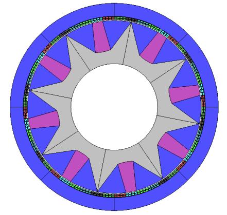
42 Figure Back EMF of Single Barrier Type Rotor Interior Type Rotor The geometry of interior type rotor (1/8) is shown as Figure 2.13 and the permanent magnet area is 162 mm^2. 24
43 Figure Geometry of Interior Type Rotor Based on FEA results, the back EMF of single barrier type rotor at 4000 RPM is shown as Figure 2.14; for shape evaluation purposes, only Phase A and Phase C are plotted. The shape of back EMF is trapezoidal. 25
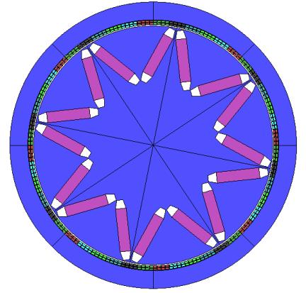
44 Figure Back EMF of Interior Type Rotor Spoke Type Rotor The geometry of spoke type rotor (1/8) is shown as Figure 2.15 and the permanent magnet area is 130 mm^2. 26
45 Figure Geometry of Spoke Type Rotor Based on FEA results, the back EMF of spoke type rotor at 4000 RPM is shown as Figure 2.16; for shape evaluation purposes, only Phase A and Phase C are plotted. The shape of back EMF is trapezoidal. 27
46 Figure Back EMF of Spoke Type Rotor Rotor Comparison Study Compliant to trapezoidal shape, back EMF principle, single barrier, interior and spoke type rotors are selected for further study because surface-mounted and inset type rotor can only provide quasi trapezoidal shape back EMF. The flux density contour and air-gap flux density of single barrier type rotor are shown as figures 2.17 and 2.18 respectively. 28
47 Figure Flux Density Contour of Single Barrier Type Rotor 29
48 Figure Air-Gap Flux Density of Single Barrier Type Rotor The flux density contour and air-gap flux density of interior type rotor are shown as figures 2.19 and 2.20, respectively. 30

49 Figure Flux Density Contour of Interior Type Rotor 31
50 Figure Air-Gap Flux Density of Interior Type Rotor The flux density contour and air-gap flux density of spoke type rotor are shown as figures 2.21 and 2.22, respectively. 32

51 Figure Flux Density Contour of Spoke Type Rotor 33
52 Figure Air-Gap Flux Density of Spoke Type Rotor Through further comparison, spoke type rotor provides the largest back EMF and most balanced flux density distribution for a given magnet size. The torque of spoke type rotor and excitation current are shown as figures 2.23 and 2.24, respectively. 34
53 Figure Torque of Spoke Type Rotor 35
54 Figure Excitation Current of Spoke Type Rotor As a conclusion, the best candidate is spoke-type interior-magnet rotor that developed to increase the air-gap flux density by the flux-concentration principle. The spoke-type interior-magnet rotor was used as an aircraft generator and in servo-motors by Fanuc and by Pacific Scientific. 2.5 Air Gap Design Based on the FEA results from above sections, rotor core structure and magnet dimension decide back EMF shape and torque capability. However, air-gap flux density is the determinant of back EMF shape and torque capability based on further study, 36
55 therefore, air gap will be studied in this section. The difference between air gap and effective air gap are shown as Figure


56 Effective Air Gap Air Gap Figure Air Gap and Effective Air Gap 38

57 It can be seen that air gap is the physical gap that is much smaller than the effective air gap. In the traditional BLDC machines, stator core has slots and teeth, shown as Figure Tooth Slot Figure Slots and Teeth in Traditional BLDC Machine The flux density in the teeth are high, while in the slots are low, resulting in the reduction of average air flux density. The effective air gap is calculated based on the Carter coefficient, l e = Cl g (2.6) where C is Carter coefficient, l e and l g are effective air gap and air gap, respectively. The Carter coefficient is determined by 39
58 C = W s+w t W s (1 σ)+w t = 1 (2.7) 1 σ W s Ws+W t where W s and W t are slot width and tooth width respectively, σ is given by σ = 2 π {tan 1 W s l g ln [1 + ( W 2 s ) ]} (2.8) 2l g W s 2l g Usually in practical design, the optimal ratio between slot width and tooth width is one. Therefore, the minimum Carter coefficient can be obtained when σ is maximized. The saturation value of σ can be found close to 0.9 by increasing the ratio between slot width and air gap. In slotless machine, slot width is zero and the Carter coefficient is one. However, the effective air gap is not equal to air gap because the permeability of winding can be considered as air. As a result, the effective air gap of slotless machine is given by where W w is winding width. l e = l g + W w (2.9) Since air gap flux density is inversely proportional to effective air gap, a smaller effective air gap can provide larger back EMF. In other words, it requires less permanent magnets to obtain the same back EMF. There are several limitations when trying reduce effective air gap. The air gap reduction is mainly limited by bearing tolerance and precision, machine manufacturing and installation. The winding width reduction needs to take into account winding current density, winding heat dissipation and winding insulation. With a reduction in effective air gap, with regard to conductor width, conductor length and insulation, a slotless six-phase BLDC machine is shown in Figure 2.27, 40

59 Figure Geometry of Machine Design with Reduction in Effective Air Gap Based on FEA results, the back EMF of machine design with reduction in effective air gap at 4000 RPM is shown as Figure 2.28; for shape evaluation purposes only, Phase A and Phase C are plotted. The shape of back EMF is trapezoidal. 41
60 Figure Back EMF of Machine Design with Reduction in Effective Air Gap The flux density contour and air-gap flux density of machine design with reduction in effective air gap are shown as figures 2.29 and 2.30 respectively. 42
61 Figure Flux Density Contour of Machine Design with Reduction in Effective Air Gap 43
62 Figure Air-Gap Flux Density of Machine Design with Reduction in Effective Air Gap The torque of machine design with reduction in effective air gap and excitation current are shown as figures 2.31 and 2.32, respectively. 44
63 Figure Torque of Machine Design with Reduction in Effective Air Gap 45
64 Figure Excitation Current of Machine Design with Reduction in Effective Air Gap The FEA simulation results showed that the machine design with reduction in effective air gap can achieve the same torque capability, but permanent magnet usage is dramatically reduced, as shown in Table
65 Table 2.4. Effective Air Gap Comparison Item Normal Effective Air Gap Reduction Unit Stator core OD mm Stator core ID (decrease) mm Rotor core OD (increase) mm Axial length mm Air Gap mm Effective Air Gap (decrease by 38%) mm Insulation thickness (decrease) mm Conductor number (increase) conductor Conductor width (decrease) mm Conductor length (decrease) mm Conductor area (decrease) mm^2 Conductor current (decrease) A Conductor current density (increase by 65%) A/( mm^2) PM width (decrease) mm PM width (decrease) mm PM length (decrease) mm PM area (decrease) mm^2 PM residual magnetism T PM coercive force KA/m Stator core volume (increase by 3%) cm^3 Rotor core volume (increase by 11%) cm^3 Conductor volume (decrease by 43%) cm^3 PM volume (decrease by 41%) cm^3 From the comparison results, machine design with reduction in effective air gap has the same air gap, but effective air gap is decreased by 38% because of the smaller conductor and thinner insulation. The smaller conductor will cause an increase in conductor current density and the thinner insulation will require a low manufacture tolerance. As a result, the 65% increase in conductor current density will cause efficiency drop and bring heat dissipation problems. In addition, machine design with reduction in effective air gap has the same outside 47
66 dimensions, with a smaller stator core inner diameter and a larger rotor core outer diameter. These two changes allow allocating more inductors and generating more torque. The cost of machine design with reduction in effective air gap will be reduced because that the PM volume can be decreased by 41% while maintaining the same torque capability, though stator core volume and rotor core are increased by 3% and 11% respectively. In summary, the original design is optimized to achieve a higher efficiency while machine design with reduction in effective air gap is optimized to use less PM material. The original design is selected for prototype production because of the high efficiency and relative ease to manufacture. The machine design with reduction in effective air gap has advantages in cost and weight and will be manufactured in the next generation. 2.6 Inductance Calculation and Measurement From the comparison results above, the air gap flux density of the original design is slightly higher, but the machine design with reduction in effective air gap has a much larger back EMF. The root cause is the inductance. In this section, the inductance of sixphase BLDC machine will be studied by different calculation methods and then inductance will be measured based on FEA simulations. In electrical machine design, when it refers to inductance calculation, flux linkage is always required. Therefore, at the beginning, the flux linkage definition will be introduced as, ψ = Li (2.10) 48
67 where L is inductance, i is current going through the inductor. Based on Faraday s law, v = ψ t (2.11) flux linkage can also be expressed as the time integration of voltage, then combine the two equations above, v = L i L + i t t (2.12) the first part in equation 2.12 is overwhelming because the rate of change of inductance with respect to time is much slower than that of the current. Assuming L is constant, then v = L i t (2.13) thus, inductance can be calculated by the terminal voltage and current. There is another way to define flux linkage, which is ψ = Nφ (2.14) where N is number of turns, φ is flux, substitute equation 2.14 into 2.10, L = Nφ i (2.15) the flux can be written as φ = FP (2.16) where F is MMF and P is permeance, then inductance can be expressed as L = N 2 P (2.17) From equation 2.17, inductance is proportional to square of number of turns. Hence, the inductance will be increased significantly by adding number of turns. For example, the original design has 8 turns while machine design with reduction in effective air has 12 turns. The turns ratio is 2 to 3 and the inductance ratio will be 4 to 9 if permeance is not 49

68 affected. Theoretically, the back EMF ratio will be 2 to 3 if air gap flux density of both cases are the same. However, form FEA simulation results, figures 2.16 and 2.28 show that the back EMF ratio is 2 to 3.2, of which the differences are caused by air gap flux density. As a result, in order to achieve the same torque capability, 37.5% current can be reduced for machine design with reduction in effective air. From equation 2.17, inductance is not only affected by turns ratio but also by permeance. Magnetic permeability is used to measure the ability of a martial to support the formation of a magnetic field within itself. Magnetic permeability is defined as, μ = B H (2.14) where B is magnetic flux density and H is magnetic field, also referred to as magnetic field strength. For example, stator core and rotor core are soft magnetic material, of which the magnetic permeability can be calculated based on Figure Figure Flux Density vs Magnetic Field of Soft Magnetic Material 50
69 Magnetic permeability of permanent magnet can be calculated based on Figure Figure Flux Density vs Magnetic Field of Permanent Magnet Material The relative permeability of air and copper is one. Since the spoke type rotor has salience, the inductance will change periodically according to the position. The inductance of the original design is shown as Figure
70 Figure Phase Inductance vs Electrical Angle of Original Design The inductance of machine design with reduction in effective air gap is shown as Figure
71 Figure Phase Inductance vs Electrical Angle of Machine Design with Reduction in Effective Air Gap Form FEA simulation results Figure 2.35 and 2.36 show that the phase inductance ratio is 1 to 3.7 because of the turns ratio and permeance. The permeance of original design is lower than that of machine design with reduction in effective air gap due to the less effective air gap and thinner permanent magnets. From Figure 2.35, the phase inductance changes periodically as rotor moves. The maximum phase A inductance is around mh, where rotor position is shown as Figure 2.37, and minimum phase A inductance is mh, where rotor position is shown as Figure

72 Figure Rotor Position with Maximum Phase A Inductance 54

73 Figure Rotor Position with Minimum Phase A Inductance 55
74 In Figure 2.37, most of the flux line does not cross the permanent magnets, resulting in a high permeance for phase A. On the contrary, in Figure 2.38, most of the flux line crosses the permanent magnets, resulting in a low permeance. In original design, mutual inductance between phase A and other phases are shown as Figure Figure Mutual Inductance between Phase A and Other Phases From Figure 2.39, mutual inductance AB, AD, AE and AF are negative signs because of the opposite coil direction. Mutual inductance AF is close to zero due to its unique position, where the number of clockwise flux lines is very close to that of anti-clockwise 56
75 flux lines. In this section, the calculation method of inductance has been derived. The influence of turns number and permeance has been analyzed. Furthermore, phase inductance and mutual inductance have been measured through the FEA simulations method. 2.7 Winding Resistance Calculation As the main reason of copper losses, stator winding resistance needs to be designed appropriately. The resistance calculation of round wire is given as, R = 4ρρn sl h πn p d 2 (2.15) where ρ is resistivity, ρ is number of slots per phase, n s is number of wires per slot, l h is half length of one single coil, n p is number of parallel wires per strand, d is diameter of wire. In slotless six-phase BLDC machine design, rectangular wire is adopted. Thus, the resistance calculation can be rewritten as, R = ρρn sl h n p l w w w (2.16) where l w is wire length and w w is wire width. Particular to this design, ρ is 64 while n s and n p are both one. The resistance of one phase winding can be calculated as R = ( ) 64 1 ( ) 1 ( ) ( ) 57 = 0.15 Ω (2.17) Usually, there is some error between real winding resistance and calculated due to endwinding connections. Winding resistance can be reduced by several methods, such as parallel wires under different poles, or simply increase the wire cross section. However, these methods will reduce winding inductance. Therefore, winding resistance cannot be designed independently; inductance and back EMF should also be considered.
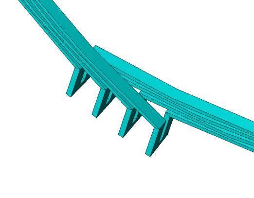
76 2.8 Winding Assembling The slotless six-phase BLDC machine has two layers of windings and each layer has 192 conductors. Conventional fixture and tooling are no longer suitable for this type of machine. Therefore, an innovative assembling process is proposed. The fixture and tooling include six types of parts as shown in Figure B A4: OD 98.4 mm A3: OD mm C A2: OD mm A1: OD mm same as stator ID 1/8 machine model Stator Core Figure Fixture and Tooling Overview In Figure 2.40, part A1, A2, A3 and A4 are slots with different outer diameters. Part B is key and part C is hollow cylinder with multiple slots. Note that outer diameter of 58
77 part A1 is the same as stator inner diameter. There are eleven steps in the assembling process. Step 1: As shown in Figure 2.41, in order to make stator and part C concentric, part A1s are used to fill the space between stator and part C. A1: OD mm same as stator ID C 1/8 machine model Figure Winding Assembling Step 1 Step 2: As shown in Figure 2.42, one of part A1 has been removed, still stator and part C are concentric. 59

78 A1: OD mm same as stator ID C 1/8 machine model Figure Winding Assembling Step 2 fix A3. Step 3: As shown in Figure 2.43, put one part A3 in the empty place and use part B to 60

79 Figure Winding Assembling Step 3 Step 4: As shown in Figure 2.44, place the first layer winding, including four conductors, in the space between part A3 and stator. Note that the conductors are downward. Then potting material is injected into the gaps between the conductors. 61

80 Figure Winding Assembling Step 4 Step 5: As shown in Figure 2.45, replace part A3 with part A2. Part A2 will extrude conductors and potting material, removing excess potting material. 62

81 Figure Winding Assembling Step 5 Step 6: As shown in Figure 2.46, repeat steps 2, 3, 4 and 5 to install first layer winding. 63

82 Figure Winding Assembling Step 6 Step 7: As shown in Figure 2.47, replace one part A2 with part A4 and use part B to fix part A4 64
83 Figure Winding Assembling Step 7 Step 8: As shown in Figure 2.48, place the second layer winding including four conductors in the space between part A4 and first layer winding. Note that the conductors are downward. Then potting material is injected into the gaps between the conductors. 65
84 Figure Winding Assembling Step 8 Step 9: As shown in Figure 2.49, replace part A4 with part A3. Part A3 will extrude conductors and potting material, removing excess potting material. 66

85 Figure Winding Assembling Step 9 Step 10: As shown in Figure 2.50, repeat steps 7, 8 and 9 to install second layer winding. 67

86 Figure Winding Assembling Step 10 Step 11: As shown in Figure 2.51, remove part C and parts A2. Then, a uniform air gap is obtained. At the meantime, both first layer and second layer windings are concentric. 68

87 Figure Winding Assembling Step Prototype In the previous sections, stator core, stator winding, rotor core and permanent magnets have been designed and verified by FEA simulations, also the manufacture fixture and tooling were proposed. The first generation prototype of slotless six-phase BLDC machine is shown in Figure

88 Nonmagnetic Materials Stator Core Permanent Magnet (not installed) Rotor Core Figure First Generation Prototype of Slotless Six-Phase BLDC Machine From Figure 2.52, the rotor core is different from the original design because of the mechanical concern. Note that the permanent magnets have not been installed on the rotor. Both stator core and rotor core are made with lamination stacks. In the center of rotor core, there is a rotor shaft as shown in Figure


89 Figure Rotor Shaft of Prototype Machine From Figure 2.53, rotor shaft is designed to support rating torque. In addition, a resolver will be mounted on the rotor shaft for rotor position measurement. Stator windings are made with 384 conductors, single conductor is shown as Figure

90 Conductors (total 384) Figure Single Conductor of Prototype Machine Two conductors are soldered together to form a coil; the conductor connections are shown as Figure

91 Figure Conductor Connections of Prototype Machine 73

92 One phase winding has 32 coils in a series connection. The whole stator windings are shown in Figure Figure Stator Windings of Prototype Machine 74


93 At last, fixture and tooling for manufacture are shown as Figure Figure Fixture and Tooling of Prototype Machine 75
94 2.10 Configuration The slotless six-phase BLDC machine can be called a multiphase machine, because the number of phases is twice that of a three-phase machine. The advantage of this multiphase machine is that a single inverter can split into smaller inverters. On the other hand, the slotless six-phase BLDC machine can be configured as a three-phase BLDC machine as shown in Figure Figure Three-Phase Configuration of Slotless Six-Phase BLDC Machine 76
95 Based on FEA results, the back EMF in three-phase configuration at 4000 RPM is shown as Figure Figure Back EMF in Three-Phase Configuration The shape of back EMF is not quite trapezoidal. Compare Figure 2.59 with 2.16, the magnitude of back EMF doubled, but the flat region decreased, making an obvious gap between two flat back EMF regions Summary In this chapter, a 3kW slotless six-phase BLDC machine has been designed. The 77
96 stator core, stator winding connection, rotor core and air gap are optimized by three principles. The first principle is performance, referring to high torque density. The second one is trapezoidal back EMF. The third one is to reduce cost by reducing the usage of permanent magnets. After geometry design and FEA validation, the inductance and resistance of stator winding is calculated. In the meantime, a winding assembling method is proposed and a prototype machine has been built. At last, the advantage of sixphase BLDC machine is that a single inverter can split into two smaller power rating inverters. 78
97 CHAPTER 3: STEPPING VECTOR CONTROL In this chapter, a novel control algorithm for slotless six-phase BLDC machine is proposed. The proposed control algorithm combines the merits of sinusoidal current control and trapezoidal current control to improve slotless six-phase BLDC machine performance. The proposed control algorithm is called SVC because the vector angle changes step by step. With the proposed algorithm, commutation torque ripple will be minimized by matched incoming and outgoing currents. Furthermore, a torque-enhanced method based on SVC is proposed. Essentially, slotless six-phase BLDC machine will be controlled as two slotless threephase BLDC machines. Phases A, C and E are grouped as one slotless three-phase BLDC machine and phase B, D and F are grouped as another one. The control algorithm in these machines is identical, the only difference is phase delay. Therefore, SVC is analyzed and derived based on three-phase BLDC machine at first. After that, a commutation torque ripple minimization method based on SVC is proposed and verified. Finally, an optimized SVC is proposed to increase torque output capability. 3.1 Stepping Vector Control of BLDC Machine BLDC and brushless AC (BLAC) machines are widely used in electric vehicle (EV) and hybrid electric vehicle (HEV) applications due to their high power density, high 79
98 torque density and high efficiency. Different from a BLAC machine with a sinusoidal back EMF, the BLDC machine is provided with a trapezoidal back EMF. Compared to a BLAC machine, a BLDC machine can achieve a higher torque density and a higher power density for a given size [36]. However, a BLDC machine has a significant drawback, which is commutation torque ripple. Commutation torque ripple will cause oscillation and resonance in mechanical components, bringing observable vibration and acoustic noise to drive systems. The ripple is caused by the currents going through the freewheeling diodes during commutation intervals, and many studies have been conducted to minimize this torque ripple. In [37], a DC bus voltage control method is proposed, but an additional DC bus voltage controller is required in the method, increasing overall system cost. In [38] an algorithm based on current slopes control is proposed, in which the current slopes of the incoming and outgoing phase currents can be controlled in the same rate of change by adjusting PWM duty ratio. By delaying the turnoff timing instant of the outgoing switch, an overlap switching algorithm is proposed in [39]. However, these conventional methods show limited effectiveness in practical applications due to machine parameter sensitivity and unsatisfactory performance over an entire speed range. An algorithm based on SVC, which combines the merits of sinusoidal current control and trapezoidal current control, is proposed to minimize commutation torque ripple in this chapter. Sinusoidal current control can be applied to BLDC machine drive but the performance will be degraded because of the large torque ripple. The torque ripple is caused by non sinusoidal back EMF. The sinusoidal current control is usually implemented by space vector control. The current, back EMF and torque waveforms are 80
99 shown in Figure I_A I_B I_C BackEMF_A Torque Time (s) Figure 3.1. Current Back EMF and Torque in Sinusoidal Current Control The trapezoidal current control is a perfect fit for BLDC machine drive because both high torque production and high efficiency [40, 41] can be achieved. The trapezoidal current control is usually implemented by hysteresis control, PI control, fuzzy logic control or feed forward control [42-45]. However, in most of the control algorithms 81
100 outgoing phase current is without control and its decay rate is only determined by DC bus voltage and back EMF. The varying decay rate may cause a mismatch between outgoing current and incoming current, resulting in a commutation torque ripple. The current, back EMF and torque waveforms are shown in Figure 3.2. I_A I_B I_C BackEMF_A Torque Time (s) Figure 3.2. Current, Back EMF and Torque in Trapezoidal Current Control In order to achieve a trapezoidal current control with commutation torque ripple 82
101 minimization, a novel vector control algorithm, the SVC, is proposed for BLDC machine drive. Similar to conventional vector control, vector angle and vector amplitude are the two control variables in SVC. The main difference lies in the vector angle s moving pattern. As the BLDC machine rotates, the vector angle moves continuously in conventional vector control, while it moves step by step in SVC. Both moving patterns are shown in Figure 3.3. Conventional Vector Control Ia Ib Ic (A) Stepping Vector Control vector_angle (degree) Time (s) Figure 3.3. Current and Vector Angle Moving Pattern in Conventional Vector Control (left) and SVC (right) The vector angle move pattern has a direct effect on current shape. In Figure 3.3, the continuous vector angle leads to a sinusoidal current and the stepping vector angle results 83
102 in a trapezoidal current with spikes. Note that in both cases, vector amplitude is kept constant, when BLDC machine rotates. In trapezoidal current control, 360 electric degrees are divided into six regions. Only two phases are conducting (active) in each region, with the other being non-conducting (inactive). The active phases and inactive phases for each region are listed in Table 3.1. Table 3.1. Active Phase and Inactive Phase in Six Regions Electrical Angle Region Active phase Inactive phase Vector Angle A, C B B, C A B, A C C, A B C, B A A, B C 330 Each of the regions can be represented as one corresponding vector angle. Therefore, in SVC algorithm, the vector angle is maintained at 30 electric degrees when the rotor moves in region 1, the resulting phase A current equals minus phase C current, the phase B current is zero. When the rotor enters region 2, the vector angle will jump to 90 electric degrees in a given commutation interval and keep at 90 electric degrees for the whole region 2, the resulting phase B current equals minus phase C current, the phase A current is zero. The same procedure is used for other regions. In this way, the current is controlled in a trapezoidal shape as expected. The implementation of the proposed SVC algorithm is shown in the block diagram in Figure
103 Figure 3.4. Block Diagram of SVC for BLDC Machine Drive System In the controller block diagram, vector amplitude is decoupled into magnetizing and torque components. By default, magnetizing current Id is set to zero in BLDC machine drive. Then vector amplitude only depends on torque current Iq. Vector angle generation is the core of SVC. The position feedback device Hall sensor can provide six commutation signals to vector angle generation. The details of vector angle generation will be discussed in the next section. 3.2 Commutation Torque Ripple Minimization of BLDC Machine In this section, an original idea of SVC algorithm will be proposed for the BLDC machine drive system, the commutation torque ripple is minimized in this algorithm by matching the slopes of incoming and outgoing phase currents. After theoretical analysis and calculation, computer simulations and experimental results will be provided to verify the proposed SVC algorithm. At last, the length of the ramping region in SVC will be discussed. 85
104 3.2.1 BLDC Commutation Torque Ripple Analysis The commutation torque ripple is caused by the currents going through the freewheeling diodes during commutation interval. For example, when the machine commutates from region 1 to region 2, the conducting status of three-phase is shown in Figure 3.5. V DC V A A B C V B Incoming Current V C Equivalent Circuit of Three Phase BLDC Machine R R R L L L E A E B E C V N Outgoing Current Figure 3.5. Equivalent Circuit of BLDC in Commutation Interval The incoming current flows through the upper leg switch of phase B and the outgoing current flows through the lower leg diode of phase A. Based on the conductions of switches and diodes, phase voltage equations during commutation intervals can be expressed as the following, 86
105 the summation of all the currents is given by Then the neutral point voltage can be calculated as V A = 0 = Ri A + L di A dt + E A + V N (3.1) V B = V DC = Ri B + L di B dt + E B + V N (3.2) V C = 0 = Ri C + L di C dt + E C + V N (3.3) i A + i B + i C = 0 (3.4) V n = 1 3 (V DC (E A + E B + E C )) (3.5) Assuming the resistance is very small that can be neglected, the slope of incoming phase B current can be calculated as { di B dt di B dt = V DC E B V N L = E B V N L when switch is on when switch is off (3.6) The slope of outgoing phase C current can be calculated as di C dt = E C V N L (3.7) When the slopes of incoming current and outgoing current do not match, it will produce a commutation torque ripple. The simulation waveforms of the incoming current, outgoing current and commutation torque ripple are shown in Figure
106 Ia Ib Ic (A) Outgoing Current Incoming Current toque (Nm) 35 Commutation Torque Ripple Time (s) Figure 3.6. Simulation Results of Commutation Torque Ripple Commutation Torque Ripple Minimization Based on SVC In the conventional methods of commutation torque ripple reduction, duty ratio has been controlled to equalize the two mismatched commutation time intervals. The limitation of these methods is that only the incoming current is controllable, while the outgoing current is not because it goes through a freewheeling diode. In SVC, all three-phase currents are under the control of switching devices. The incoming and outgoing currents can be manipulated to have matched slopes during the 88
107 commutation interval. The implementation is based on vector angle control and vector angle is kept as 30 electric degrees when rotor is rotating in region 1 until Hall sensor sends a commutation signal. The vector angle will change rapidly from 30 to 90 electric degrees in a given commutation time and then maintain at 90 when rotor is at region 2. During commutation interval, three-phase currents are all conducting. The outgoing current is decreasing to zero while incoming current is increasing from zero, both of them are with the same rate of change. Though the slopes are matched, spikes still existed in the commutation interval as in Figure 3.3. In addition, the vector amplitude can be adjusted during the commutation interval. In order to minimize commutation torque ripple, vector amplitude will be compensated as a function of vector angle, which can be written as A vector = 1 sin (60+(θ vector %60)) (3.8) where A vector and θ vector are vector amplitude and vector angle, respectively Ideal trapezoidal current waveforms during commutation interval are shown as Figure Figure 3.7. Ideal Current for Commutation Torque Ripple Minimization 89
108 Torque equation of BLDC machine is given by, T e = 1 ω m (E A i A + E B i B + E C i C ) (3.9) In region 1, for example, only phase A and phase C are conducting. The currents and back EMFs of these two phases satisfy Torque equation can be simplified as i A = i C (3.10) E A = E C (3.11) T e = 1 ω m (E C i C + E C i C ) (3.12) During the commutation interval, all three phases are conducting. The currents and back EMFs of these three phases satisfy Torque equation can be simplified as i A + i B = i C (3.13) E A = E B = E C (3.14) T e = 1 ω m (E C i C + E C i C ) (3.15) Based equations 3.12 and 3.15, the torque will not change during commutation interval in the proposed SVC algorithm Simulation Verification A computer model of the BLDC system with proposed SVC algorithm, as shown in Figure 3.4, has been developed in PSIM simulator. The simulation results are shown in Figure
109 Only with Vector Angle Control Vector Angle Control with Vector Amplitude Compensation Ia Ib Ic (A) vector_angle (degree) vector_amplitude (per-unit value) Id_command Id_feedback Iq_command Iq_feedback (per-unit value) Torque (Nm) Time (s) Figure 3.8. Simulation Results of SVC In SVC, with the control of vector angle and vector amplitude, the currents work in a trapezoidal shape and the slopes of incoming and outgoing phase currents are matched. As a result, the commutation torque ripple is minimized Experimental Verification To further verify the effectiveness of the proposed SVC algorithm, experimental 91
110 testing is conducted on an actual BLDC machine system. The parameters of the tested BLDC machine are given in Table 3.2. Table 3.2. Rating and Parameters of BLDC Machine Nominal power 1 hp Nominal voltage 230 V Nominal current 2.4 A Number of pole pairs 2 Base speed 1800 rpm Stator Resistance 2.9 Ω Mutual inductance 64 mh Figure 3.9 shows the current waveform only with vector angle control, thus the trapezoidal current can be found with spikes during commutation interval. Figure 3.9. Experimental Results of Current with Vector Angle Control in SVC 92
111 Figure 3.10 shows the current waveform with both vector angle and vector amplitude control. Due to vector amplitude compensation, the current spikes are eliminated and the commutation torque ripple is minimized. The commutation torque ripple is reduced to less than 20%, which can also be found in Figure 3.8. Figure Experimental Results of Current with both Vector Angle and Vector Amplitude Control in SVC Ramping Region of SVC As shown in Figure 3.11, vector angle includes two types of regions: the flat region and the ramping region. Most of the time, vector angle stays at the flat region. The flat region ends when a commutation signal is triggered by the Hall position sensor. 93
112 Meanwhile vector angle will enter the ramping region, which corresponds to the commutation interval. 250 vector_angle (degree) Ramping Region Flat Region Triggered by Controller Triggered by Hall sensor real_rotor_angle (degree) Time (s) Figure Vector Angle and Real Rotor Angle in SVC The ramping region is not terminated by the Hall position sensor, but by a controller. As a result, the vector angle in the ramping region is an artificial angle, which is unrelated to the real rotor angle. Therefore, the length of ramping region is controllable. Usually vector angle is requested to change quickly to achieve a short commutation 94
113 interval because of the limited overlap between two adjacent flat regions. However, the current through an inductor cannot change instantaneously. If the commutation interval is too short, the current cannot follow the vector angle, and vector amplitude commands, though, that the PI controller is well tuned. Hence, it is easier to implement the optimal commutation interval at low speeds than at high speeds because real angle moves faster. The length of ramping region should be chosen as a tradeoff between speed and current amplitude. 3.3 Enhanced Torque Control of BLDC Machine In this section, an original idea of enhanced torque control will be proposed for the BLDC machine drive system, the torque output is enhanced by matching back EMFs and phase currents. After theoretical analysis and calculation, simulations will be provided to verify the proposed control algorithm Optimal Current in Enhanced Torque Control In interior permanent magnet machine control, usually maximum torque per ampere (MTPA) control is adopted to increase torque output. In order to take advantage of reluctance torque, the MTPA angle varies as current amplitude changes. When current amplitude stays the same, the MTPA angle will not change. Different from the concept of MTPA control, optimal current angle in enhanced torque control is referred to the stator current angle that generate maximum torque when amplitude of stator current vector does not change. The optimal current angle is 95
114 calculated based on back EMFs. For ideal sinusoidal back EMFs, the optimal current angle is the same as the position angle, which will be verified later in this section. In practice, back EMFs are non-ideal sinusoidal, therefore, the optimal current angle will not exactly align with the position angle. In general, the MTPA angle can be considered as a way to achieve enhanced torque macroscopically, while the optimal current angle is used to obtain enhanced torque microscopically. The reluctance torque is not considered in the following analysis of optimal current angle in enhanced torque control. In a Y connection type BLDC machine, the threephase currents will satisfy the following equation, i A + i A + i C = 0 (3.16) either conventional vector control or SVC is applied, the phase angle difference is 120 degrees and phase A current is defined as i A = I sin(θ) (3.17) where I is current amplitude and θ is current angle. As a result, phase B and phase C currents can be expressed as Then, equation 3.9 can be rewritten as i B = I sin(θ 120 ) (3.18) i C = I sin(θ ) (3.19) T e = 1 ω m (E A I sin(θ) + E B I sin(θ 120 ) + E C sin(θ )) (3.20) Equation 3.20 can be simplified as T e = 1 ω m (I sin(θ) (E A 1 2 E B 1 2 E C) + I cos(θ) ( 3 2 E B E C)) (3.21) The derivative of equation 3.21 is 96
 The extreme value of torque can be obtained, when θ satisfies 0 = cos(θ) (E A 1 2 E B 1 2 E C) sin(θ) ( 3 2 E B + 3 2 E C) (3.")
115 d(t e ) = 1 (I cos(θ) (E d(θ) ω A 1 E m 2 B 1 E 2 C) I sin(θ) ( 3 E 2 B + 3 E 2 C)) (3.22) The extreme value of torque can be obtained, when θ satisfies 0 = cos(θ) (E A 1 2 E B 1 2 E C) sin(θ) ( 3 2 E B E C) (3.23) which can also be expressed as θ = tan 1 ( E A 1 2 E B 1 2 E C ) (3.24) 3 2 E B+ 3 2 E C From equation 3.24, optimal current angle θ is calculated based on three-phase back EMFs. Trapezoidal back EMFs and optimal current angle θ are shown as Figure Figure Optimal Current Angle Control In figure 3.12, back EFMs are trapezoidal. The optimal current angle θ is shown with rotor position angle. The angle difference between optimal current angle and rotor position angle is less than one degree. The average torque increases by 5.4% from 1.30 Nm in SVC to 1.37 Nm in optimal current angle control. However, there are torque 97
116 ripples in optimal current angle control. In order to reduce the torque, vector amplitude will be compensated as a function of back EMFs, which can be written as A vector = T request 1 ωm (I sin(θ) (E A 1 2 E B 1 2 E C)+I cos(θ) ( 3 2 E B+ 3 2 E C)) (3.25) where A vector is vector amplitude, T request is request torque and θ is obtained through equation Optimal current angle with vector amplitude compensation is shown as Figure Figure Optimal Current Angle Control with Vector Amplitude Compensation Simulation Verification A computer model of the BLDC system with proposed optimal current angle control algorithm has been developed in PSIM simulator. The simulation results are shown in Figure In optimal current angle control, with the control of vector angle and vector 98
117 amplitude, the currents work in a quasi-sinusoid shape and the phase currents and back EMFs are matched. As a result, the torque output is enhanced and torque ripple is minimized. BackEMF_A BackEMF_B BackEMF_C (V) optimal_current_angle Ia Ib Ic (A) (degree) Id_command Id_feedback Iq_command Iq_feedback (per-unit value) Torque (Nm) Time (s) Figure Simulation Results of Optimal Current Angle Control 3.4 Summary In this chapter, an original SVC algorithm has been proposed for BLDC machine drive system; the commutation torque ripple is minimized in this algorithm by matching 99
118 the slopes of incoming and outgoing phase currents. Computer simulations and experimental results are provided to verify the proposed SVC algorithm. Furthermore, an enhanced torque control of the BLDC machine has been proposed. Based on three-phase back EMFs, an optimal current angle can be calculated. The optimal current angle control can provide 5.4% more torque than conventional control, but with a drawback of torque ripple. At last, the torque ripple in optimal current angle control is minimized by vector amplitude compensation. 100
119 CHAPTER 4: SENSORLESS CONTROL OF BLDC MACHINE In this chapter, a sensorless BLDC control algorithm based on rotor saliency is proposed. A voltage pulse injection method is used for inductance measurement and the peak inductance current is measured through the salient phase to increase accuracy. Zero speed and arbitrary low speed sensorless operations can be achieved with the proposed algorithm. Finite element analysis method (FEM) simulations and experimental results are provided to verify the proposed control algorithm. This chapter is organized as follows: the rotor saliency characteristics are discussed at the beginning. Then, the principles of the algorithm for the BLDC zero speed starting and low speed operation are described. Later on, FEM simulations and experimental testing are conducted and results are presented to verify the effectiveness of the proposed sensorless control algorithm. A summary is presented as the last section. 4.1 Rotor Saliency Characteristics BLDC machines have been widely used in electric vehicles, servo systems and appliances due to their high efficiency and high torque density. In high performance applications, the BLDC machine is driven by an inverter and it requires rotor position information for current commutations. Usually a group of Hall position sensors provides commutation signals. In order to reduce cost and enhance mechanical robustness, a 101
120 variety of sensorless control algorithms have been studied [53-57]. In three-phase BLDC machine control algorithms, usually two of the three phases are conducting sequentially and the other non-conducting phase is called silent phase. In order to obtain commutation timings, the back EMF method detects the back EMF zero crossing of the silent phase and triggers the commutations every 60 degrees [53], while [54] integration the back EMF of the silent phase compared with a threshold value. It should be pointed out that these above mentioned methods, as well as other flux linkage based ones [55, 56] and freewheeling diode conduction methods [57], fail to achieve commutation at zero or low speed because of the undetectable back EMFs. To overcome the mentioned drawbacks, a sensorless method based on speed-independent function is proposed in [58], which can estimate commutation instants from near zero (2% of the rated speed) to high speed. However, this method is only applicable to the surface-mounted permanent magnet BLDC machines. A BLDC machine sensorless control algorithm based on inductance variation is proposed in [59]. In this algorithm, a pulse train, including long and short pulses, is injected into the conducting phases. The long pulses are used for torque production and the short ones are for inductance measurement. However, a time interval insertion between the long and the short pulses is required to ensure measurement accuracy. During the time interval a negative torque is generated, leading to a degraded torque performance. Other sensorless algorithms for a permanent magnet synchronous machine, including magnetic pole identifications, high frequency injection and sliding-mode control, have been investigated in [60-64]. However, these methods based on space vector control are preferred by sinusoidal current drive rather than trapezoidal current BLDC drive. 102
121 The proposed sensorless control algorithm for BLDC machines is based on rotor saliency. A voltage pulse injection method is used for inductance measurement and the peak inductance current is measured to improve rotor detection accuracy. For the speed ranging from zero to an arbitrarily low speed, sensorless operations of the BLDC can be achieved with the proposed algorithm. The saliency characteristics are studied through a typical BLDC model using the finite element analysis method (FEM) as shown in Figure 4.1. Stator Core Winding Permanent Magnet Rotor Core Figure 4.1. Typical BLDC Machine FEM Model (1/4) By the FEM simulation results, the variation of phase inductance and line inductance are functions of the BLDC rotor position as presented in figures 4.2 and 4.3, respectively. For convenience of investigation, one electrical cycle is divided into six regions by commutation points and each region covers 60 electrical degrees. 103
122 0.16 Region 0 Region 1 Region 2 Region 3 Region 4 Region 5 L(mH) A B C Rotor Position (electric degree) Figure 4.2. Phase Inductance Variation Region 0 Region 1 Region 2 Region 3 Region 4 Region 5 L(mH) AB BC CA Rotor Position (electric degree) Figure 4.3. Line Inductance Variation Note that, in both phase inductance and line inductance simulation results, inductance 104
123 data in deep magnetic saturation conditions are not provided, because in the real situation, the current for inductance measurement is always less than 20% of the rated current. Figures 4.2 and 4.3 reveal that both the phase inductance and line inductance vary with the rotor position in a quasi-sinusoidal manner. For example, across Region 0 where the rotor position lies within 0 to 60 degrees, the phase inductance of Phase C remains the smallest among the three, while Phase A inductance keeps increasing and Phase B decreasing. A similar quasi-sinusoidal manner can also be found in the line inductance, where, for the same region, AB inductance is the largest, while CA inductance keeps increasing and BC decreasing. Such kind of manners could provide us not only the information about which region the rotor lies in, but also a method of detecting commutation points. In other words, the specific rotor position can be acquired by knowing phase inductance or line inductance. 4.2 Sensorless Control of BLDC Machine from Zero to Low Speed As discussed in the last section, it is revealed that the rotor position and the phase and line inductance are closely inter related, which provides an insight of sensorless control of a BLDC machine. However, directly measuring the phase or line inductance involves complicated processes and requires additional circuits in the BLDC system. Therefore, a more practical method is adopted in this chapter. As is well known, when applying a voltage across an ideal inductor, the current flowing through the inductor will increase linearly. The rate of increase is proportional to the inverse of the inductance and the magnitude of the applied voltage. However, if the voltage, as well as the amount of time the voltage applied on the inductor, is fixed, the peak current is inversely proportional to 105
124 the inductance. Therefore, by measuring the inductor peak current, which is simple and easy to implement, the inductance information can be obtained, as well as the rotor position. However, BLDC machine winding is not an idealized inductor because of the resistance. Therefore, the voltage applying time has to be as short as possible to minimize the effect of resistance. As mentioned above, information of both the phase inductance and line inductance can be utilized as an indicator for the rotor position detection. However, the neutral point of BLDC machines is usually not available for measurement, making it impossible to obtain the phase inductance information. Therefore, it is logical that the obtainable line inductance information is utilized to realize sensorless control of the BLDC machine. In a BLDC machine system, if DC bus voltage V DC is applied across any two terminals of the three phases, the voltage equation of the circuit, where the voltage drop across the resistor is neglected, can be expressed as V DC = L pp (θ) di pp dt (4.1) where L pp (θ) represents the position-dependent line inductance, and i pp is the current flowing in the corresponding phases. Define the smallest amount of time that the voltage is applied on stator phases to be one unit of Voltage Applying Period (VAP) t VAP, then, during one VAP, the current variation i pp can be expressed as i pp = V DC t VAP L pp (θ) (4.2) As can be seen, if t VAP is kept constant, the current variation is in inverse proportion with the line inductance. Assuming that there is no current in the corresponding phases before the voltage is applied, and then only by measuring the peak current at the end of VAP, the line inductance at arbitrary rotor position can be indirectly obtained. 106
125 4.2.1 Principles of Initial Rotor Position Estimation Algorithm As discussed in previous sections, the six regions are marked in Figure 4.3, with each region characterized by a line inductance being the largest throughout that region. It is well known that BLDC machines have six operational regions, and each of them requires specified phase currents, which are shown in Figure 4.4 with arrows. Phase A A+ B- Region 1, i CA_min C+ B- Phase C A+ C- Region 2, i BC_min Region 0, i AB_min C+ A- Region 3, i AB_min Region 5, i BC_min Region 4, i CA_min B+ C- B+ A- Phase B Figure 4.4. Characterizing Current Region Instead of the characterizing line inductance, the characterizing current is marked for each region. A typical three-phase BLDC machine drive system is shown in Figure
126 IDC S1 S3 S5 VDC A B BDCM32 BLDC BDCM C S4 S6 S2 Figure 4.5. Typical BLDC Machine System The implementation is conducted in the following sequences: first, energize A-B phases for one VAP. At the end of that VAP, sample the DC bus current i AB. Second, wait until i AB drops to zero. Third, repeat the first two steps to energize B-C phases and C-A phases in sequence, and sample the DC bus current i BC and i CA. Then, by comparing the sampled currents, the rotor position could be preliminarily located. For instance, if i AB is the smallest among the three sampled currents, then the rotor can be considered to lie in either Region 0 or Region 3 according to figures 4.3 and 4.4. Further operation has to be adopted to pinpoint the rotor position, and this process is called the magnet polarity determination, which is based on the core saturation effect. Forth, a positive voltage is applied to certain phases depending on the rotor s preliminary position for eight VAPs, which is sufficient to produce large currents to saturate the core. 108
127 For example, still assuming that the rotor position is preliminarily located in Region 0 or Region 3, then Phase A and C are chosen to be energized because voltage VA+C- or VC+Awill produce the most likely flux to saturate BLDC machine. A large current will be generated and i P will be sampled at the end of the last VAP. Fifth, after i P drops to zero, apply a negative voltage to the same phases for the same amount of time, 8 VAPs, and sample i N at the end of 8 VAPs. One of them will produce a flux in alignment with the rotor flux and saturate the core, hence the current is much larger than the other one. The comparison procedure is presented in Table 4.1. Table 4.1. Initial Position Estimation Comparison Procedure Min(iAB, ibc, ica) i AB i BC i CA Polarity Determination Phases A-C B-A B-C i P, i N Comparison i P > i N i P < i N i P > i N i P < i N i P > i N i P < i N North Pole Position (Region Number) Starting Current B+ & A- A+ & B- C+ & B- B+ & C- C+ & A- A+ & C- Compared with the initial rotor position estimation method discussed in [66], where six saturation currents are injected, the proposed algorithm uses five current pulses to locate the initial rotor position, only two of which are saturation currents. It minimizes the damage that saturation current might cause and reduces the time of initial rotor position estimation. 109
128 4.2.2 Principles of Low Speed Sensorless Algorithm When the BLDC machine works in low speed operation, the back EMF based methods are not applicable. The initial rotor position estimation algorithm is also not applicable because it requires large detection currents and long operation time. The magnet polarity determination currents are usually greater than rated current, so that the BLDC machine will suffer from a large torque ripple. In addition, the initial rotor position estimation algorithm needs a long time interval to complete five current samplings and the long time interval insertion will bring serious disturbance to normal operation. To overcome the drawbacks, a low speed sensorless control of BLDC machine based on line inductance variation is proposed. Theoretically, all three line inductances can be used for commutation timing estimation, as shown in Figure 4.3. However, not all of them are practical to be utilized to trigger a commutation. The conducting line inductance is difficult to measure because of the PWM chopping. The feasibility of the other two line inductances is analyzed as following. When the BLDC machine is at region 0, Phase A and Phase B are conducting. As shown in Figure 4.3, B-C line inductance decreases during the first 30 degrees and stays steady from 30 to 90 degrees, while C-A inductance stays steady at first and increases later. Assuming that the BLDC machine is moving to region 1, the variation rate of C-A line inductance is much higher near the commutation point, compared to B-C line inductance. The line inductance with an obvious variation at commutation point makes itself a prominent candidate for low speed sensorless control. If the BLDC machine is 110
129 moving in the opposite direction, B-C line inductance will be chosen for sensorless control. The sensorless algorithm in other regions will follow the same procedure and the corresponding injected voltage is given in Table 4.2. Table 4.2. Rotor Position and Injected Voltage Injected Voltage Region Clockwise Motion CA BC AB AC CB BA Anti-clockwise Motion CB BA CA BC AB AC In order to acquire C-A line inductance, C-A current pulses need to be measured. Assuming the rotor position is in Region 0, where Phase A and B are conducting. When the PWM is ON, the current goes through V DC -S1-Phase A-Phase B-S6-V DC, shown in Figure 4.5, and I DC is equal to i AB. On the other hand, when the PWM is OFF, the current flows in the loop D4-phase A-phase B-S6-D4, and I DC is zero. If, during OFF state, Phase C and A are energized by turning on S5 and S4, then the DC current would be the same when the current goes through C-A phases. In other words, by measuring the DC current, the C-A inductance could be acquired, and so is the rotor position. Based on the principle discussed above, the implementation is conducted as follows. For every N (N could be any number, for instance, 100) DSP interrupt cycles, one voltage pulse is injected to certain phases for several VAPs and the corresponding current is sampled at the end of the last VAP. Every time, the sampled current is compared with a pre-determined value, and if the sampled current drops below this value, a commutation will be triggered. Figure 4.6 shows the flowchart of the proposed algorithm. 111
130 Send Pulse Sample DC Current Smaller than Threshold Current? No Yes Commutation Figure 4.6. Flowchart of the Low Speed Sensorless Algorithm 4.3 Simulation Verification Both initial rotor position estimation algorithm and low speed sensorless algorithm are tested by FEM simulations. In the simulation, the North Pole of the rotor is fixed at 30 degrees, and voltage pulses are applied on A-B, B-C and C-A phases in sequence. Figure 4.7 shows the FEM results of the sampled DC current. 112
131 Current (A) i A i B i C Time (s) Figure 4.7. Inductance Measurement Currents in FEM simulation After that, A-C phases are energized with positive and negative voltages, and the DC current is shown in Figure i N Current (A) i P South Pole North Pole Time (s) Figure 4.8. North Pole Detection Currents in FEM simulation The results that i AB is the smallest and i P is the biggest implies, based on Table 4.1, 113
132 that the North Pole is located in Region 0, which matches the 30 degrees position. After the North Pole is identified, the BLDC machine can start rotating from zero speed by applying A+B- voltage. Further simulation is conducted to illustrate the current variation as the rotor rotates from 0 to 60 degrees, as shown in Figure
133 Current (A) Rotor Position (electric degree) (a) Current Pulse in AB Current (A) Rotor Position (electric degree) (b) Current Pulse in BC Current (A) threshold Rotor Position (electric degree) (c) Current Pulse in CA Figure 4.9. Current Variation in Region 0 115

134 It verifies that C-A current is the most suitable candidate in triggering a commutation in Region 0. In addition, the threshold trigger is marked in Figure Experimental Verification To verify the effectiveness of the proposed control algorithm, an experimental test has been conducted on a real BLDC machine drive system. Figure 4.10 shows the lab setup of the BLDC machine system. Figure BLDC Machine Drive System The machine s parameters are given in Table 4.3. Table 4.3. Rating and Parameters of BLDC Machine Nominal power 1 hp Nominal voltage 230 V Nominal current 2.4 A Number of pole pairs 2 Base speed 1800 rpm Stator Resistance 2.9 Ω Mutual inductance 64 mh Saliency Yes 116
135 Figure 4.11 shows the experimental results of the current response after applying voltage pulses to the standstill BLDC machine. i A i B i C i B i C i A Figure Inductance Measurement Currents in Experiment The blue trace represents the current as it goes through Phase A, pink is Phase B, and green is Phase C. The part of the waveforms above the central line can be regarded as the DC bus current. It is followed by the North Pole detection, and the current responses are shown in Figure
136 South Pole North Pole i A i A Figure North Pole Detection Currents in Experiment The blue trace is the current in Phase A, and the red one is its absolute value, which can be treated as the DC bus current as well. Figures 4.11 and 4.12 match perfectly with the simulation results shown in figures 4.7 and 4.8. The experimental results of a sensor-based operation and the proposed sensorless operation are compared in figures
137 with sensor sensorless Figure Sensor-based and Sensorless Comparison The BLDC machine shifts from sensor-based operation to sensorless operation at the dashed line, the commutation point is detected precisely and the performance under sensorless operation is as good as it is under sensor-based operation. Figure 4.14 reveals the detailed sensorless operation within 60 degrees. 119
138 i A i B i C threshold Region 0 (0 to 60 electric degrees) Figure Inductance Measurement Currents From top to bottom are the currents of Phase A, Phase B and Phase C. The center of the screen, where A-B phases are conducting, corresponds to Region 0 in Figure 4.3. The sampled DC bus current, which is also the absolute value of the sampled Phase C current, decreases in this interval. The commutation is conducted when the sampled Phase C current reaches the threshold. The Phase C current matches with the simulation result shown in Figure 4.9 (c). The proposed algorithm is also tested under a low speed operation. Figure 4.15 shows the three phase currents when the BLDC machine is operating at an extremely low speed, 8.5 RPM, which is less than 0.5% of the rating speed. 120

139 Figure Extremely Low Speed Operation Given that this algorithm is only position dependent, it can be utilized at an arbitrary low speed as long as the saliency exists. 4.5 Summary In this chapter, a sensorless control algorithm for a BLDC machine at zero and low speed based on rotor saliency is proposed. FEM simulations are conducted on a BLDC machine to reveal the dependence of the phase inductance and line inductance on the rotor positions. Algorithms for the detecting rotor position at standstill and extreme low speed are proposed based on line inductance variation and are verified by both FEM simulation and experimental testing. The advantages of the proposed control algorithm 121
Analysis of Losses in High Speed Slotless PM Synchronous Motor Integrated the Added Leakage Inductance
 International Conference on Power Electronics and Energy Engineering (PEEE 2015) Analysis of Losses in High Speed Slotless PM Synchronous Motor Integrated the Added Leakage Inductance B.Q. Kou, H.C. Cao
Generalized Theory Of Electrical Machines
 Essentials of Rotating Electrical Machines Generalized Theory Of Electrical Machines All electrical machines are variations on a common set of fundamental principles, which apply alike to dc and ac types,
Sensorless Control of a Novel IPMSM Based on High-Frequency Injection
 Sensorless Control of a Novel IPMSM Based on High-Frequency Injection Xiaocan Wang*,Wei Xie**, Ralph Kennel*, Dieter Gerling** Institute for Electrical Drive Systems and Power Electronics,Technical University
Analog Devices: High Efficiency, Low Cost, Sensorless Motor Control.
 Analog Devices: High Efficiency, Low Cost, Sensorless Motor Control. Dr. Tom Flint, Analog Devices, Inc. Abstract In this paper we consider the sensorless control of two types of high efficiency electric
A Study on Distributed and Concentric Winding of Permanent Magnet Brushless AC Motor
 Volume 118 No. 19 2018, 1805-1815 ISSN: 1311-8080 (printed version); ISSN: 1314-3395 (on-line version) url: http://www.ijpam.eu ijpam.eu A Study on Distributed and Concentric Winding of Permanent Magnet
Key Factors for the Design of Synchronous Reluctance Machines with Concentrated Windings
 IEEE PEDS 27, Honolulu, USA 2 5 December 27 Key Factors for the Design of Synchronous Reluctance Machines with Concentrated Windings Tobias Lange, Claude P. Weiss, Rik W. De Doncker Institute for Power
UG Student, Department of Electrical Engineering, Gurunanak Institute of Engineering & Technology, Nagpur
 A Review: Modelling of Permanent Magnet Brushless DC Motor Drive Ravikiran H. Rushiya 1, Renish M. George 2, Prateek R. Dongre 3, Swapnil B. Borkar 4, Shankar S. Soneker 5 And S. W. Khubalkar 6 1,2,3,4,5
Rare-Earth-Less Motor with Field Poles Excited by Space Harmonics
 Rare-Earth-Less Motor with Field Poles Excited by Space Harmonics Theory of Self-Excitation and Magnetic Circuit Design Masahiro Aoyama Toshihiko Noguchi Department of Environment and Energy System, Graduate
Analysis of an Economical BLDC Drive System
 Analysis of an Economical BLDC Drive System Maria Shaju 1, Ginnes.K.John. 2 M.Tech Student, Dept. of Electrical and Electronics Engineering, Rajagiri School of Engineering and Technology, Kochi, India
Contents. About the Authors. Abbreviations and Symbols
 About the Authors Preface Abbreviations and Symbols xi xiii xv 1 Principal Laws and Methods in Electrical Machine Design 1 1.1 Electromagnetic Principles 1 1.2 Numerical Solution 9 1.3 The Most Common
A new dual stator linear permanent-magnet vernier machine with reduced copper loss
 A new dual stator linear permanent-magnet vernier machine with reduced copper loss Fangfang Bian, 1,2) and Wenxiang Zhao, 1,2) 1 School of Electrical and Information Engineering, Jiangsu University, Zhenjiang
ACOUSTIC NOISE AND VIBRATIONS DUE TO MAGNETIC FORCES IN ROTATING ELECTRICAL MACHINES
 TECHNICAL TRAINING TTR01 ACOUSTIC NOISE AND VIBRATIONS DUE TO MAGNETIC FORCES IN ROTATING ELECTRICAL MACHINES 1 OBJECTIVES The objectives of the full technical training including all option modules are
Sensorless control of BLDC motor based on Hysteresis comparator with PI control for speed regulation
 Sensorless control of BLDC motor based on Hysteresis comparator with PI control for speed regulation Thirumoni.T 1,Femi.R 2 PG Student 1, Assistant Professor 2, Department of Electrical and Electronics
Jean LE BESNERAIS 26/09/ EOMYS ENGINEERING / /
 Fast calculation of acoustic noise and vibrations due to magnetic forces during basic and detailed design stages of electrical machines using MANATEE software Jean LE BESNERAIS 26/09/18 contact@eomys.com
VIENNA RECTIFIER FED BLDC MOTOR
 VIENNA RECTIFIER FED BLDC MOTOR Dr. P. Sweety Jose #1, R.Gowthamraj *2, #Assistant Professor, * PG Scholar, Dept. of EEE, PSG College of Technology, Coimbatore, India 1psj.eee@psgtech.ac.in, 2 gowtham0932@gmail.com
Smooth rotation. An adaptive algorithm kills jerky motions in motors.
 Page 1 of 4 Copyright 2004 Penton Media, Inc., All rights reserved. Printing of this document is for personal use only. For reprints of this or other articles, click here Smooth rotation An adaptive algorithm
Evaluation of a New Dual-Rotor Hybrid Excitation Brushless Motor
 Progress In Electromagnetics Research C, Vol. 86, 233 245, 2018 Evaluation of a New Dual-Rotor Hybrid Excitation Brushless Motor Libing Jing *, Jia Cheng, Qixing Gao, Ting Zhang, and Ying Lin Abstract
CHAPTER-III MODELING AND IMPLEMENTATION OF PMBLDC MOTOR DRIVE
 CHAPTER-III MODELING AND IMPLEMENTATION OF PMBLDC MOTOR DRIVE 3.1 GENERAL The PMBLDC motors used in low power applications (up to 5kW) are fed from a single-phase AC source through a diode bridge rectifier
EEE, St Peter s University, India 2 EEE, Vel s University, India
 Torque ripple reduction of switched reluctance motor drives below the base speed using commutation angles control S.Vetriselvan 1, Dr.S.Latha 2, M.Saravanan 3 1, 3 EEE, St Peter s University, India 2 EEE,
Modeling and Simulation Analysis of Eleven Phase Brushless DC Motor
 Modeling and Simulation Analysis of Eleven Phase Brushless DC Motor Priyanka C P 1,Sija Gopinathan 2, Anish Gopinath 3 M. Tech Student, Department of EEE, Mar Athanasius College of Engineering, Kothamangalam,
Simulation of Solar Powered PMBLDC Motor Drive
 Simulation of Solar Powered PMBLDC Motor Drive 1 Deepa A B, 2 Prof. Maheshkant pawar 1 Students, 2 Assistant Professor P.D.A College of Engineering Abstract - Recent global developments lead to the use
Swinburne Research Bank
 Swinburne Research Bank http://researchbank.swinburne.edu.au Tashakori, A., & Ektesabi, M. (2013). A simple fault tolerant control system for Hall Effect sensors failure of BLDC motor. Originally published
Analysis of Indirect Temperature-Rise Tests of Induction Machines Using Time Stepping Finite Element Method
 IEEE TRANSACTIONS ON ENERGY CONVERSION, VOL. 16, NO. 1, MARCH 2001 55 Analysis of Indirect Temperature-Rise Tests of Induction Machines Using Time Stepping Finite Element Method S. L. Ho and W. N. Fu Abstract
Design of A Closed Loop Speed Control For BLDC Motor
 International Refereed Journal of Engineering and Science (IRJES) ISSN (Online) 2319-183X, (Print) 2319-1821 Volume 3, Issue 11 (November 214), PP.17-111 Design of A Closed Loop Speed Control For BLDC
Optimizing Performance Using Slotless Motors. Mark Holcomb, Celera Motion
 Optimizing Performance Using Slotless Motors Mark Holcomb, Celera Motion Agenda 1. How PWM drives interact with motor resistance and inductance 2. Ways to reduce motor heating 3. Locked rotor test vs.
3. What is hysteresis loss? Also mention a method to minimize the loss. (N-11, N-12)
") DHANALAKSHMI COLLEGE OF ENGINEERING, CHENNAI DEPARTMENT OF ELECTRICAL AND ELECTRONICS ENGINEERING EE 6401 ELECTRICAL MACHINES I UNIT I : MAGNETIC CIRCUITS AND MAGNETIC MATERIALS Part A (2 Marks) 1. List
DHANALAKSHMI COLLEGE OF ENGINEERING, CHENNAI DEPARTMENT OF ELECTRICAL AND ELECTRONICS ENGINEERING EE 6401 ELECTRICAL MACHINES I UNIT I : MAGNETIC CIRCUITS AND MAGNETIC MATERIALS Part A (2 Marks) 1. List
1249. Development of large salient-pole synchronous machines by using fractional-slot concentrated windings
 1249. Development of large salient-pole synchronous machines by using fractional-slot concentrated windings Tayfun Gundogdu 1, Guven Komurgoz 2 Istanbul Technical University, Department of Electrical Engineering,
CHAPTER 6 FABRICATION OF PROTOTYPE: PERFORMANCE RESULTS AND DISCUSSIONS
 80 CHAPTER 6 FABRICATION OF PROTOTYPE: PERFORMANCE RESULTS AND DISCUSSIONS 6.1 INTRODUCTION The proposed permanent magnet brushless dc motor has quadruplex winding redundancy armature stator assembly,
3. What is the difference between Switched Reluctance motor and variable reluctance stepper motor?(may12)
") EE6703 SPECIAL ELECTRICAL MACHINES UNIT III SWITCHED RELUCTANCE MOTOR PART A 1. What is switched reluctance motor? The switched reluctance motor is a doubly salient, singly excited motor. This means that
EE6703 SPECIAL ELECTRICAL MACHINES UNIT III SWITCHED RELUCTANCE MOTOR PART A 1. What is switched reluctance motor? The switched reluctance motor is a doubly salient, singly excited motor. This means that
CHAPTER 2 STATE SPACE MODEL OF BLDC MOTOR
 29 CHAPTER 2 STATE SPACE MODEL OF BLDC MOTOR 2.1 INTRODUCTION Modelling and simulation have been an essential part of control system. The importance of modelling and simulation is increasing with the combination
SPEED CONTROL OF PERMANENT MAGNET SYNCHRONOUS MOTOR USING VOLTAGE SOURCE INVERTER
 SPEED CONTROL OF PERMANENT MAGNET SYNCHRONOUS MOTOR USING VOLTAGE SOURCE INVERTER Kushal Rajak 1, Rajendra Murmu 2 1,2 Department of Electrical Engineering, B I T Sindri, (India) ABSTRACT This paper presents
Vienna Rectifier Fed BLDC Motor
 Vienna Rectifier Fed BLDC Motor Dr. P. Sweety Jose 1, R.Gowthamraj 2 1 Assistant Professor, 2 PG Scholar, Dept. of Electrical & Electronics Engg., PSG College of Technology, Coimbatore 1 psj.eee@psgtech.ac.in
Step vs. Servo Selecting the Best
 Step vs. Servo Selecting the Best Dan Jones Over the many years, there have been many technical papers and articles about which motor is the best. The short and sweet answer is let s talk about the application.
The effect analysis of single-double layers concentrated winding on squirrel cage induction motor
 International Conference on Advanced Electronic Science and Technology (AEST 2016) The effect analysis of single-double layers concentrated winding on squirrel cage induction motor a Jianjun Fang, Yufa
CHAPTER 4 FUZZY BASED DYNAMIC PWM CONTROL
 47 CHAPTER 4 FUZZY BASED DYNAMIC PWM CONTROL 4.1 INTRODUCTION Passive filters are used to minimize the harmonic components present in the stator voltage and current of the BLDC motor. Based on the design,
Extended Speed Current Profiling Algorithm for Low Torque Ripple SRM using Model Predictive Control
 Extended Speed Current Profiling Algorithm for Low Torque Ripple SRM using Model Predictive Control Siddharth Mehta, Md. Ashfanoor Kabir and Iqbal Husain FREEDM Systems Center, Department of Electrical
ADVANCED CONTROL METHODS FOR TORQUE RIPPLE REDUCTION AND PERFORMANCE IMPROVEMENT IN SWITCHED RELUCTANCE MOTOR DRIVES
 ADVANCED CONTROL METHODS FOR TORQUE RIPPLE REDUCTION AND PERFORMANCE IMPROVEMENT IN SWITCHED RELUCTANCE MOTOR DRIVES ADVANCED CONTROL METHODS FOR TORQUE RIPPLE REDUCTION AND PERFORMANCE IMPROVEMENT IN
CHAPTER 3 VOLTAGE SOURCE INVERTER (VSI)
") 37 CHAPTER 3 VOLTAGE SOURCE INVERTER (VSI) 3.1 INTRODUCTION This chapter presents speed and torque characteristics of induction motor fed by a new controller. The proposed controller is based on fuzzy
37 CHAPTER 3 VOLTAGE SOURCE INVERTER (VSI) 3.1 INTRODUCTION This chapter presents speed and torque characteristics of induction motor fed by a new controller. The proposed controller is based on fuzzy
SIMULATION AND IMPLEMENTATION OF CURRENT CONTROL OF BLDC MOTOR BASED ON A COMMON DC SIGNAL
 SIMULATION AND IMPLEMENTATION OF CURRENT CONTROL OF BLDC MOTOR BASED ON A COMMON DC SIGNAL J.Karthikeyan* Dr.R.Dhanasekaran** * Research Scholar, Anna University, Coimbatore ** Research Supervisor, Anna
SPEED CONTROL OF BRUSHLES DC MOTOR
 SPEED CONTROL OF BRUSHLES DC MOTOR Kajal D. Parsana 1, Prof. H.M. Karkar 2, Prof. I.N. Trivedi 3 1 Department of Electrical Engineering, Atmiya Institute of Technology & Science, Rajkot, India. kajal.parsana@gmail.com
Unequal Teeth Widths for Torque Ripple Reduction in Permanent Magnet Synchronous Machines With Fractional-Slot Non-Overlapping Windings
 Unequal Teeth Widths for Torque Ripple Reduction in Permanent Magnet Synchronous Machines With Fractional-Slot Non-Overlapping Windings Ilya Petrov, Pavel Ponomarev, Yulia Alexandrova, Juha Pyrhönen, LUT
Simulation and Dynamic Response of Closed Loop Speed Control of PMSM Drive Using Fuzzy Controller
 Simulation and Dynamic Response of Closed Loop Speed Control of PMSM Drive Using Fuzzy Controller Anguru Sraveen Babu M.Tech Student Scholar Dept of Electrical & Electronics Engineering, Baba Institute
Challenges and Solutions for IPMSM to be Used as a Next Generation Electrical Machine
 Proceedings of the 2011 International Conference on Industrial Engineering and Operations Management Kuala Lumpur, Malaysia, January 22 24, 2011 Challenges and Solutions for IPMSM to be Used as a Next
Sensorless Control of BLDC Motor Drive Fed by Isolated DC-DC Converter
 Sensorless Control of BLDC Motor Drive Fed by Isolated DC-DC Converter Sonia Sunny, Rajesh K PG Student, Department of EEE, Rajiv Gandhi Institute of Technology, Kottayam, India 1 Asst. Prof, Department
ADVANCED ROTOR POSITION DETECTION TECHNIQUE FOR SENSORLESS BLDC MOTOR CONTROL
 International Journal of Soft Computing and Engineering (IJSCE) ISSN: 3137, Volume, Issue-1, March 1 ADVANCED ROTOR POSITION DETECTION TECHNIQUE FOR SENSORLESS BLDC MOTOR CONTROL S.JOSHUWA, E.SATHISHKUMAR,
OPTIMUM DESIGN ASPECTS OF A POWER AXIAL FLUX PMSM
 OPTIMUM DESIGN ASPECTS OF A POWER AXIAL FLUX PMSM PAUL CURIAC 1 Key words: High-energy permanent magnets, Permanent magnet synchronous machines, Finite element method analysis. The paper presents an axial
Noise and Vibration in PM Motors Sources and Remedies
 Noise and Vibration in PM Motors Sources and Remedies 1 A typical Rubber Ferrite Magnet Iso / Anisotropic Iso Iso Remanence Coercive Force Intrinsic Coercive Force Max. Energy Product Br Hcb Hcj (BH)max
DESIGN STUDY OF LOW-SPEED DIRECT-DRIVEN PERMANENT-MAGNET MOTORS WITH CONCENTRATED WINDINGS
 1 DESIGN STUDY OF LOW-SPEED DIRECT-DRIVEN PERMANENT-MAGNET MOTORS WITH CONCENTRATED WINDINGS F. Libert, J. Soulard Department of Electrical Machines and Power Electronics, Royal Institute of Technology
Low Cost Power Converter with Improved Performance for Switched Reluctance Motor Drives
 ISSN (Online) : 2319-8753 ISSN (Print) : 2347-6710 International Journal of Innovative Research in Science, Engineering and Technology Volume 3, Special Issue 3, March 2014 2014 International Conference
Efficiency Optimized Brushless DC Motor Drive. based on Input Current Harmonic Elimination
 Efficiency Optimized Brushless DC Motor Drive based on Input Current Harmonic Elimination International Journal of Power Electronics and Drive System (IJPEDS) Vol. 6, No. 4, December 2015, pp. 869~875
Fuzzy Logic Controller Based Direct Torque Control of PMBLDC Motor
 Fuzzy Logic Controller Based Direct Torque Control of PMBLDC Motor Madasamy P 1, Ramadas K 2, Nagapriya S 3 1, 2, 3 Department of Electrical and Electronics Engineering, Alagappa Chettiar College of Engineering
Mohammad Sedigh Toulabi. A thesis submitted in partial fulfillment of the requirements for the degree of. Doctor of Philosophy.
 Wide Speed Range Operation of Concentrated Winding Interior Permanent Magnet Synchronous Machines by Mohammad Sedigh Toulabi A thesis submitted in partial fulfillment of the requirements for the degree
This is a repository copy of Permanent-magnet brushless machines with unequal tooth widths and similar slot and pole numbers.
 This is a repository copy of Permanent-magnet brushless machines with unequal tooth widths and similar slot and pole numbers. White Rose Research Online URL for this paper: http://eprints.whiterose.ac.uk/862/
PWM SWITCHING STRATEGY FOR TORQUE RIPPLE MINIMIZATION IN BLDC MOTOR
 Journal of ELECTRICAL ENGINEERING, VOL. 62, NO. 3, 2011, 141 146 PWM SWITCHING STRATEGY FOR TORQUE RIPPLE MINIMIZATION IN BLDC MOTOR Wael A. Salah Dahaman Ishak Khaleel J. Hammadi This paper describes
IN MANY industrial applications, ac machines are preferable
 IEEE TRANSACTIONS ON INDUSTRIAL ELECTRONICS, VOL. 46, NO. 1, FEBRUARY 1999 111 Automatic IM Parameter Measurement Under Sensorless Field-Oriented Control Yih-Neng Lin and Chern-Lin Chen, Member, IEEE Abstract
Control of Electric Machine Drive Systems
 Control of Electric Machine Drive Systems Seung-Ki Sul IEEE 1 PRESS к SERIES I 0N POWER ENGINEERING Mohamed E. El-Hawary, Series Editor IEEE PRESS WILEY A JOHN WILEY & SONS, INC., PUBLICATION Contents
Simulation and Dynamic Response of Closed Loop Speed Control of PMSM Drive Using Fuzzy Controller
 Simulation and Dynamic Response of Closed Loop Speed Control of PMSM Drive Using Fuzzy Controller Anguru Sraveen Babu M.Tech Student Scholar Department of Electrical & Electronics Engineering, Baba Institute
Winding Function Analysis Technique as an Efficient Method for Electromagnetic Inductance Calculation
 Winding Function Analysis Technique as an Efficient Method for Electromagnetic Inductance Calculation Abstract Electromagnetic inductance calculation is very important in electrical engineering field.
New Direct Torque Control of DFIG under Balanced and Unbalanced Grid Voltage
 1 New Direct Torque Control of DFIG under Balanced and Unbalanced Grid Voltage B. B. Pimple, V. Y. Vekhande and B. G. Fernandes Department of Electrical Engineering, Indian Institute of Technology Bombay,
International Journal of Intellectual Advancements and Research in Engineering Computations
 www.ijiarec.com MAR-2015 International Journal of Intellectual Advancements and Research in Engineering Computations SPEED CONTROL OF BLDC MOTOR BY USING UNIVERSAL BRIDGE WITH ABSTRACT ISSN: 2348-2079
A Comparative Study of Sinusoidal PWM and Space Vector PWM of a Vector Controlled BLDC Motor
 A Comparative Study of Sinusoidal PWM and Space Vector PWM of a Vector Controlled BLDC Motor Lydia Anu Jose 1, K. B.Karthikeyan 2 PG Student, Dept. of EEE, Rajagiri School of Engineering and Technology,
BECAUSE OF their low cost and high reliability, many
 824 IEEE TRANSACTIONS ON INDUSTRIAL ELECTRONICS, VOL. 45, NO. 5, OCTOBER 1998 Sensorless Field Orientation Control of Induction Machines Based on a Mutual MRAS Scheme Li Zhen, Member, IEEE, and Longya
TABLE OF CONTENTS CHAPTER NO. TITLE PAGE NO. LIST OF TABLES LIST OF FIGURES LIST OF SYMBOLS AND ABBREVIATIONS
 vii TABLE OF CONTENTS CHAPTER NO. TITLE PAGE NO. ABSTRACT LIST OF TABLES LIST OF FIGURES LIST OF SYMBOLS AND ABBREVIATIONS iii xii xiii xxi 1 INTRODUCTION 1 1.1 GENERAL 1 1.2 LITERATURE SURVEY 1 1.3 OBJECTIVES
THE UNIVERSITY OF BRITISH COLUMBIA. Department of Electrical and Computer Engineering. EECE 365: Applied Electronics and Electromechanics
 THE UNIVERSITY OF BRITISH COLUMBIA Department of Electrical and Computer Engineering EECE 365: Applied Electronics and Electromechanics Final Exam / Sample-Practice Exam Spring 2008 April 23 Topics Covered:
SYNCHRONOUS MACHINES
 SYNCHRONOUS MACHINES The geometry of a synchronous machine is quite similar to that of the induction machine. The stator core and windings of a three-phase synchronous machine are practically identical
A COMPARISON STUDY OF THE COMMUTATION METHODS FOR THE THREE-PHASE PERMANENT MAGNET BRUSHLESS DC MOTOR
 A COMPARISON STUDY OF THE COMMUTATION METHODS FOR THE THREE-PHASE PERMANENT MAGNET BRUSHLESS DC MOTOR Shiyoung Lee, Ph.D. Pennsylvania State University Berks Campus Room 120 Luerssen Building, Tulpehocken
Sensorless Position Estimation in Fault-Tolerant Permanent Magnet AC Motor Drives with Redundancy
 Sensorless Position Estimation in Fault-Tolerant Permanent Magnet AC Motor Drives with Redundancy Jae Sam An Thesis submitted for the degree of Doctor of Philosophy The School of Electrical & Electronic
Optimum design and research on novel vehicle hybrid excitation synchronous generator
 Optimum design and research on novel vehicle hybrid excitation synchronous generator Zhong-Shu Liu * The Key Laboratory for Automotive Electronics and Electric Drive of Fujian Province /School of Information
CHAPTER 2 LITERATURE REVIEW
 20 CHAPTER 2 LITERATURE REVIEW 2.1 INTRODUCTION The two major challenges on which the improvements required for the permanent magnet brushless DC motor drive systems are: a) Harmonics present in the voltage
Performance evaluation of fractional-slot tubular permanent magnet machines with low space harmonics
 ARCHIVES OF ELECTRICAL ENGINEERING DOI 10.1515/aee-2015-0049 VOL. 64(4), pp. 655-668 (2015) Performance evaluation of fractional-slot tubular permanent magnet machines with low space harmonics Jiabin Wang
A NEW C-DUMP CONVERTER WITH POWER FACTOR CORRECTION FEATURE FOR BLDC DRIVE
 International Journal of Electrical and Electronics Engineering Research (IJEEER) ISSN 2250-155X Vol. 3, Issue 3, Aug 2013, 59-70 TJPRC Pvt. Ltd. A NEW C-DUMP CONVERTER WITH POWER FACTOR CORRECTION FEATURE
Reduction of Harmonics and Torque Ripples of BLDC Motor by Cascaded H-Bridge Multi Level Inverter Using Current and Speed Control Techniques
 Reduction of Harmonics and Torque Ripples of BLDC Motor by Cascaded H-Bridge Multi Level Inverter Using Current and Speed Control Techniques A. Sneha M.Tech. Student Scholar Department of Electrical &
FOR the last decade, many research efforts have been made
 IEEE TRANSACTIONS ON POWER ELECTRONICS, VOL. 19, NO. 6, NOVEMBER 2004 1601 A Novel Approach for Sensorless Control of PM Machines Down to Zero Speed Without Signal Injection or Special PWM Technique Chuanyang
The effect of winding topologies on the performance of flux-switching permanent magnet machine having different number of rotor poles
 ARCHIVES OF ELECTRICAL ENGINEERING VOL. 7(), pp. 5 55 () DOI.5/aee..7 The effect of winding topologies on the performance of flux-switching permanent magnet machine having different number of rotor poles
Performance Optimization Using Slotless Motors and PWM Drives
 Motion Control Performance Optimization Using Slotless Motors and PWM Drives TN-93 REV 1781 Section 1: Abstract Smooth motion, meaning very low position and current loop error while at speed, is critical
Performance Improvement of BLDC Motor Based on Quasi-Z Source Network
 Performance Improvement of BLDC Motor Based on Quasi-Z Source Network N.Tharun Ram 1 G.Balaji 2 1PG Scholar, Department of EEE, Gudlavalleru Engineering College, Gudlavalleru, Krishna Dt, Andhra Pradesh,
Synchronous Current Control of Three phase Induction motor by CEMF compensation
 Synchronous Current Control of Three phase Induction motor by CEMF compensation 1 Kiran NAGULAPATI, 2 Dhanamjaya Appa Rao, 3 Anil Kumar VANAPALLI 1,2,3 Assistant Professor, ANITS, Sangivalasa, Visakhapatnam,
Mitigation of Cross-Saturation Effects in Resonance-Based Sensorless Switched Reluctance Drives
 Mitigation of Cross-Saturation Effects in Resonance-Based Sensorless Switched Reluctance Drives K.R. Geldhof, A. Van den Bossche and J.A.A. Melkebeek Department of Electrical Energy, Systems and Automation
POWER ISIPO 29 ISIPO 27
 SI NO. TOPICS FIELD ISIPO 01 A Low-Cost Digital Control Scheme for Brushless DC Motor Drives in Domestic Applications ISIPO 02 A Three-Level Full-Bridge Zero-Voltage Zero-Current Switching With a Simplified
User Guide IRMCS3041 System Overview/Guide. Aengus Murray. Table of Contents. Introduction
 User Guide 0607 IRMCS3041 System Overview/Guide By Aengus Murray Table of Contents Introduction... 1 IRMCF341 Application Circuit... 2 Sensorless Control Algorithm... 4 Velocity and Current Control...
Brushless DC Motor Drive using Modified Converter with Minimum Current Algorithm
 Brushless DC Motor Drive using Modified Converter with Minimum Current Algorithm Ajin Sebastian PG Student Electrical and Electronics Engineering Mar Athanasius College of Engineering Kerala, India Benny
Permanent Magnet Synchronous Motor Control with Speed Feedback Using a Resolver
 Permanent Magnet Synchronous Motor Control with Speed Feedback Using a Resolver I Nagulapati Kiran, II Anitha Nair AS, III D. Sri Lakshmi I,II,III Assistant Professor, Dept. of EEE, ANITS, Visakhapatnam,
User Guide Introduction. IRMCS3043 System Overview/Guide. International Rectifier s imotion Team. Table of Contents
 User Guide 08092 IRMCS3043 System Overview/Guide By International Rectifier s imotion Team Table of Contents IRMCS3043 System Overview/Guide... 1 Introduction... 1 IRMCF343 Application Circuit... 2 Power
Volume 1, Number 1, 2015 Pages Jordan Journal of Electrical Engineering ISSN (Print): , ISSN (Online):
: , ISSN (Online):") JJEE Volume, Number, 2 Pages 3-24 Jordan Journal of Electrical Engineering ISSN (Print): 249-96, ISSN (Online): 249-969 Analysis of Brushless DC Motor with Trapezoidal Back EMF using MATLAB Taha A. Hussein
JJEE Volume, Number, 2 Pages 3-24 Jordan Journal of Electrical Engineering ISSN (Print): 249-96, ISSN (Online): 249-969 Analysis of Brushless DC Motor with Trapezoidal Back EMF using MATLAB Taha A. Hussein
Simulation Study of MOSFET Based Drive Circuit Design of Sensorless BLDC Motor for Space Vehicle
 Simulation Study of MOSFET Based Drive Circuit Design of Sensorless BLDC Motor for Space Vehicle Rajashekar J.S. 1 and Dr. S.C. Prasanna Kumar 2 1 Associate Professor, Dept. of Instrumentation Technology,
Synchronous Reluctance Machine: Combined Star-Delta Winding and Rotor Eccentricity
 Synchronous Reluctance Machine: Combined Star-Delta Winding and Rotor Eccentricity Bishal Silwal, Mohamed N. Ibrahim, and Peter Sergeant Φ Abstract A permanent magnet assisted synchronous reluctance machine
PART 2 - ACTUATORS. 6.0 Stepper Motors. 6.1 Principle of Operation
 6.1 Principle of Operation PART 2 - ACTUATORS 6.0 The actuator is the device that mechanically drives a dynamic system - Stepper motors are a popular type of actuators - Unlike continuous-drive actuators,
Investigations of Fuzzy Logic Controller for Sensorless Switched Reluctance Motor Drive
 IOSR Journal of Electrical and Electronics Engineering (IOSR-JEEE) e-issn: 2278-1676,p-ISSN: 2320-3331, Volume 11, Issue 1 Ver. I (Jan Feb. 2016), PP 30-35 www.iosrjournals.org Investigations of Fuzzy
A Dynamic Modeling Permanent Magnet Synchronous Motor Drive System
 A Dynamic Modeling Permanent Magnet Synchronous Motor Drive System MISS. KINJAL G. PATEL P.G. Student, Department of Electrical Engineering SSSRGI, Vadasma, Mehsana MR. CHIRAG V. PATEL Assistant Professor,
Electromagnetic and thermal model for Brushless PM motors
 22 December 2017 Motor-CAD Software Tutorial: Electromagnetic and thermal model for Brushless PM motors Contents 1. Description... 1 2. Model Definition... 2 3. Machine Geometry... 3 4. Winding Definition...
Estimation of Vibrations in Switched Reluctance Motor Drives
 American Journal of Applied Sciences 2 (4): 79-795, 2005 ISS 546-9239 Science Publications, 2005 Estimation of Vibrations in Switched Reluctance Motor Drives S. Balamurugan and R. Arumugam Power System
CHAPTER 2 CURRENT SOURCE INVERTER FOR IM CONTROL
 9 CHAPTER 2 CURRENT SOURCE INVERTER FOR IM CONTROL 2.1 INTRODUCTION AC drives are mainly classified into direct and indirect converter drives. In direct converters (cycloconverters), the AC power is fed
1. Introduction 1.1 Motivation and Objectives
 1. Introduction 1.1 Motivation and Objectives Today, the analysis and design of complex power electronic systems such as motor drives is usually done using a modern simulation software which can provide
Motor-CAD Brushless PM motor Combined electromagnetic and thermal model (February 2015)
") Motor-CAD Brushless PM motor Combined electromagnetic and thermal model (February 2015) Description The Motor-CAD allows the machine performance, losses and temperatures to be calculated for a BPM machine.
Motor-CAD Brushless PM motor Combined electromagnetic and thermal model (February 2015) Description The Motor-CAD allows the machine performance, losses and temperatures to be calculated for a BPM machine.
Code No: R Set No. 1
 Code No: R05310204 Set No. 1 III B.Tech I Semester Regular Examinations, November 2007 ELECTRICAL MACHINES-III (Electrical & Electronic Engineering) Time: 3 hours Max Marks: 80 Answer any FIVE Questions
The Effects of Air-Gap Width on Performance of Brushless Doubly Fed Machine with Radial Laminated Reluctance Rotor
 International Forum on Management, Education and Information Technology Application (IFMEITA 2016) The Effects of Air-Gap Width on Performance of Brushless Doubly Fed Machine with Radial Laminated Reluctance
R. W. Erickson. Department of Electrical, Computer, and Energy Engineering University of Colorado, Boulder
 R. W. Erickson Department of Electrical, Computer, and Energy Engineering University of Colorado, Boulder 13.2.3 Leakage inductances + v 1 (t) i 1 (t) Φ l1 Φ M Φ l2 i 2 (t) + v 2 (t) Φ l1 Φ l2 i 1 (t)
A Practical Method of BLDCM Based on High-precision Estimation of the Rotor Position
 Engineering Letters, 4:, EL_4 04 A Practical Method of BLDCM Based on High-precision Estimation of the Rotor ZHOU Aiguo, YANG Lang, PAN Qiangbiao, SHEN Yong Abstract Approaches of staring sensorless BLDCM
Reduction of Torque Ripple in Trapezoidal PMSM using Multilevel Inverter
 Reduction of Torque Ripple in Trapezoidal PMSM using Multilevel Inverter R.Ravichandran 1, S.Sivaranjani 2 P.G Student [PSE], Dept. of EEE, V.S.B. Engineering College, Karur, Tamilnadu, India 1 Assistant
Speed control of sensorless BLDC motor with two side chopping PWM
 IOSR Journal of Electrical and Electronics Engineering (IOSR-JEEE) e-issn: 2278-1676,p-ISSN: 2320-3331, Volume 6, Issue 3 (May. - Jun. 2013), PP 16-20 Speed control of sensorless BLDC motor with two side