SMD Ferrite Selection
|
|
|
- Harry Terence Hopkins
- 6 years ago
- Views:
Transcription

1 SMD Ferrite Selection lex Snijder Field pplication Engineer Wurth Electronik Nederland BV December 2014 LED EVENT s-hertogenbosch

2 GEND What is a Chip Bead? CBF Details Losses Calculations Selecting the right Chip Bead Tooling (demo) if we have time Otherwise visit our stand 2

3 The Würth Group strong family 3

4 The Würth Elektronik Group 4

5 Globally available. Locally present. 5


6 CBF DETILS Passive device It s just an inductor Removal of unwanted noise at high frequencies for a PCB solution Supply voltage lines, ground planes, and data signals Removes noise energy in form of heat law of conservation of energy Energy cannot be created nor destroyed, only converted Frequency dependant K (lso Known s) frequency dependent resistor Material specific Material must be non conductive 6


7 CBF DETILS General use High frequency 7
8 LOSSES Inductors 1. pplication: Storage inductor 1. Request: Lowest possible core losses at switching frequency (HIGH Q) /May/2012 V2 MSz Confidential Ferrite Selection TBD Ferrite Q = X R L 2. pplication: bsorber / Filter 1. Request: Highest possible core losses at application frequency (LOW Q) 8

9 Effect of impedance in high speed signal line MHz C.M MHz D.M MHz C. M MHz D.M MHz Too much impedance distorts the USB 2.0 eye pattern Source: TDC Corporation BSF-B02E
10 INSERTION LOSS CLCULTION Z Z F U 1 U 2 Z B Source Coupling way Load System attenuation Impedance = 20 log Z + Z + Z F B Z + Z B Z F = B ( ) ( ) Z + Z Z Z B in (db) in (Ω) The logarithmic ratio of input power to output power, which describes the signal attenuation along a defined transmission patch. The signal path could be a micro stip. 10
11 INSERTION LOSS CLCULTION 11

12 INSERTION LOSS CLCULTION 1 Ω Ground plane 10 Ω Supply voltage line 50 Ω - 90 Ω Data signal lines 12
13 INSERTION LOSS CLCULTION 13
14 INSERTION LOSS CLCULTION Z Z Z F F F = = = Ω ( Z + Z ) ( Z + Z ) ( ) ( ) B B B B 1. Require 12dB of attenuation at 125 MHz 2. Know that it is a power cable 3. Power port has 10 Ω impedance 4. Result is a impedance of 60 Ω Z = 20 log 10 = 20 log = db + Z Z = 20 log F Z + Z B F 10 B + 10 B B 14

15 INSERTION LOSS CLCULTION 1. 1.Require 12dB of attenuation at 125 MHz 2. Know that it is a power cable 12dB 3. Power port has 10 Ω impedance 4. Result is a impedance of 60 Ω 60Ω 15
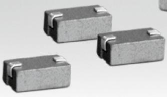
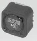
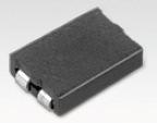
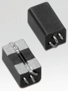
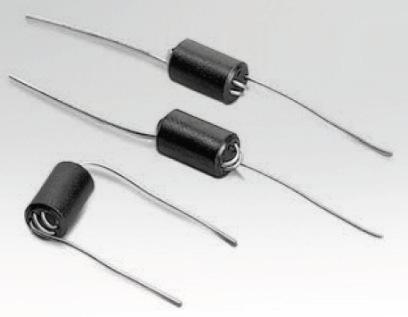

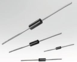
16 Other components to consider Same function as a chip bead ferrite Different sizes and turn counts needed for application driven devices. ll used as a devices to attenuate high frequency noise. 16
17 Selecting the right feritte How do I know what s the best ferrite bead for me? PPLICTION To chose the proper bead, you should consider the following: Frequency range of the noise Source of noise mount of attenuation needed Environmental and electrical parameters of the circuit (not covert in this presentation) mbient temperature DC bias current Maximum operating current Frequency of the useful signal Real estate 17


18 CHOOSING CBF USING COMPONENT SELECTOR 18


19 CHOOSING CBF USING COMPONENT SELECTOR Step 1: Having impedance given frequency of noise, click on add own frequency button to visualize the table desired frequency (eg: 125Mhz) 19
20 CHOOSING CBF USING COMPONENT SELECTOR Step 2: Filtering with Impedance Ohm header column cell, the impedance range 20


21 CHOOSING CBF USING COMPONENT SELECTOR Step 3: Filtering with the IDC embedded filter dialog box the current values or range 21


22 CHOOSING CBF USING COMPONENT SELECTOR Step 4: Select the size, RDC, ect 22


23 CHOOSING CBF USING COMPONENT SELECTOR Click on the highlighted box to see the graph 23


24 CHOOSING CBF USING COMPONENT SELECTOR It s possible to use the dd filter button as alternative to step 1 and 2 24
Multilayer ferrites with in-rush current capability
 Multilayer ferrites with in-rush current capability Alex Snijder Field Application Engineer Wurth Elektronik Nederland BV Alex.snijder@we-online.com AGENDA SMT chip bead ferrites Impedance Application
Battery Impedance Measurement
 Page 1 of 8 Using the Bode 100 and the Picotest J2111A Current Injector Page 2 of 8 Table of Contents 1 Executive Summary...3 2 Measurement Task...3 3 Measurement Setup & Results...4 3.1.1 Device Setup...5
Class-D Audio Power Amplifiers: PCB Layout For Audio Quality, EMC & Thermal Success (Home Entertainment Devices)
") Class-D Audio Power Amplifiers: PCB Layout For Audio Quality, EMC & Thermal Success (Home Entertainment Devices) Stephen Crump http://e2e.ti.com Audio Power Amplifier Applications Audio and Imaging Products
Class-D Audio Power Amplifiers: PCB Layout For Audio Quality, EMC & Thermal Success (Home Entertainment Devices) Stephen Crump http://e2e.ti.com Audio Power Amplifier Applications Audio and Imaging Products
Electro-Magnetic Interference and Electro-Magnetic Compatibility (EMI/EMC)
") INTROUCTION Manufacturers of electrical and electronic equipment regularly submit their products for EMI/EMC testing to ensure regulations on electromagnetic compatibility are met. Inevitably, some equipment
INTROUCTION Manufacturers of electrical and electronic equipment regularly submit their products for EMI/EMC testing to ensure regulations on electromagnetic compatibility are met. Inevitably, some equipment
EMC Refresh Presented by Sylvain LE BRAS Würth Elektronik eisos France
 EMC Refresh Presented by Sylvain LE BRAS Würth Elektronik eisos France Agenda WHAT IS EMC? INDUCTIVE EMC SOLUTIONS BASICS INSERTION LOSS OF INDUCTIVE SOLUTIONS CAPACITIVE EMC SOLUTIONS BASICS INSERTION
Master Thesis. Mobile Phone Antenna Modelling. Umut Bulus. Supervised by Prof. Dr.-Ing. K. Solbach
 Master Thesis Mobile Phone Antenna Modelling Umut Bulus Supervised by Prof. Dr.-Ing. K. Solbach 2.3.28 Contents Introduction Theoretical Background Antenna Measurements on Different PCB Variations Investigation
CAL U100B CAL U100B CDN M016 CAL U100B CDN M016 CAL U100B. Used as M2 CDN. Used as M3 CDN
 out < +0 out < +0 ch. < +0 ch. < +0 ch. < +7 ch. < +0 ch. < +0 ch. < +7 LL LL nd nd 0 8... Test setup calibration with a CDN The calibration setup always refers to the type of CDN. The CDN user manuals
Ansoft Designer Tutorial ECE 584 October, 2004
 Ansoft Designer Tutorial ECE 584 October, 2004 This tutorial will serve as an introduction to the Ansoft Designer Microwave CAD package by stepping through a simple design problem. Please note that there
Solving Electromagnetic Interference (EMI) with Ferrites
 with Ferrites") Solving Electromagnetic Interference (EMI) with Ferrites What are ferrites? How do ferrites help Suppress EMI? How to chose proper ferrite and component Material Characteristics Material and Core Selection
Solving Electromagnetic Interference (EMI) with Ferrites What are ferrites? How do ferrites help Suppress EMI? How to chose proper ferrite and component Material Characteristics Material and Core Selection
Mini Evaluation Board for Filterless Class-D Audio Amplifier EVAL-SSM2301-MINI
 Mini Evaluation Board for Filterless Class-D Audio Amplifier EVAL-SSM30-MINI FEATURES DC power supply accepts.5 V to 5.5 V Single-ended and differential input capability Extremely small board size allows
ELC 4383 RF/Microwave Circuits I Laboratory 4: Quarter-Wave Impedance Matching Network
 1 ELC 4383 RF/Microwave Circuits I Laboratory 4: Quarter-Wave Impedance Matching Network Note: This lab procedure has been adapted from a procedure written by Dr. Larry Dunleavy and Dr. Tom Weller at the
Welcome to Wurth Elelctronics Product Training Module about coupled inductors for the use in SEPIC converters. The PTM will explain the functionality
 Welcome to Wurth Elelctronics Product Training Module about coupled inductors for the use in SEPIC converters. The PTM will explain the functionality of a SEPIC converter and how to design coupled inductors
HV739 ±100V 3.0A Ultrasound Pulser Demo Board
 HV79 ±00V.0A Ultrasound Pulser Demo Board HV79DB Introduction The HV79 is a monolithic single channel, high-speed, high voltage, ultrasound transmitter pulser. This integrated, high performance circuit
Development of a noval Switched Beam Antenna for Communications
 Master Thesis Presentation Development of a noval Switched Beam Antenna for Communications By Ashraf Abuelhaija Supervised by Prof. Dr.-Ing. Klaus Solbach Institute of Microwave and RF Technology Department
Categorized by the type of core on which inductors are wound:
 Inductors Categorized by the type of core on which inductors are wound: air core and magnetic core. The magnetic core inductors can be subdivided depending on whether the core is open or closed. Equivalent
CHQ SERIES. Surface Mount Chip Capacitors: Ultra High Frequency
 26 High Frequency Measurement and Performance of High Multilayer Ceramic Capacitors Introduction Capacitors used in High Frequency applications are generally used in two particular circuit applications:
"High Frequency Ceramic Solutions"
 2.45 GHz High Gain Chip Antenna ( Orientation P/N 2450AT45A100 Detail Specification: 01/05/2012 Page 1 of 10 General Specifications Part Number Frequency Range Peak Gain Average Gain 2450AT45A100 2400-2500
Review: The MFJ-223 Vector Impedance Antenna Analyzer Phil Salas AD5X
 Review: The Vector Impedance Antenna Analyzer Phil Salas AD5X The is MFJ s latest entry in the antenna analyzer market. Its TFT multi-color display provides a large amount of information on a very compact
nrf905-evboard nrf905 Evaluation board PRODUCT SPECIFICATION GENERAL DESCRIPTION
 nrf905 Evaluation board nrf905-evboard GENERAL DESCRIPTION This document describes the nrf905-evboard and its use with the Nordic Semiconductor nrf905 Single Chip 433/868/915MHz RF Transceiver. nrf905-
Characteristics of Crystal. Piezoelectric effect of Quartz Crystal
 Characteristics of Crystal Piezoelectric effect of Quartz Crystal The quartz crystal has a character when the pressure is applied to the direction of the crystal axis, the electric change generates on
Fourth Year Antenna Lab
 Fourth Year Antenna Lab Name : Student ID#: Contents 1 Wire Antennas 1 1.1 Objectives................................................. 1 1.2 Equipments................................................ 1
Chapter 3 Simulation
 Chapter 3 Simulation Pulse Response Simulation [Single-end] (Setting) Pulse waves used in digital transmission include the fundamental frequency and its harmonics. Harmonics signals are easily emitted
Course Introduction. Content 16 pages. Learning Time 30 minutes
 Course Introduction Purpose This course discusses techniques for analyzing and eliminating noise in microcontroller (MCU) and microprocessor (MPU) based embedded systems. Objectives Learn what EMI is and
PHYS 3322 Modern Laboratory Methods I AC R, RC, and RL Circuits
 Purpose PHYS 3322 Modern Laboratory Methods I AC, C, and L Circuits For a given frequency, doubling of the applied voltage to resistors, capacitors, and inductors doubles the current. Hence, each of these
Measuring crystal motional parameters with the MiniVNA. Joop, PE1CQP
 Measuring crystal motional parameters with the MiniVNA Joop, PE1CQP This document is a short manual for a software program to use the MiniVNA for measuring crystal parameters. It is inspired by documents
MARTIN - G8JNJ ECLECTIC AETHER - ADVENTURES WITH AMATEUR RADIO
 MARTIN - G8JNJ ECLECTIC AETHER - ADVENTURES WITH AMATEUR RADIO REDUCING RTL DONGLE INTERNAL SPURII AND NOISE SIGNALS I ve recently bought quite a few RTL DVB-T RTL 2832U / Rafael Micro R820T dongles to
CMC 14 Common Mode Chokes Series
 7 Electrical Data ID Code Inductance Value at C (-/+%) Less than % performance variations versus temperature (- C / + C) Minimum impedance attenuation : Ω from khz to MHz Compact SMD package (x pins) Applied
Application Note 1330
 HMPP-3865 MiniPAK PIN Diode High Isolation SPDT Switch Design for 1.9 GHz and 2.45 GHz Applications Application Note 133 Introduction The Avago Technologies HMPP-3865 parallel diode pair combines low inductance,
Course Introduction. Content 15 pages. Learning Time 30 minutes
 Course Introduction Purpose This course discusses techniques for analyzing and eliminating noise in microcontroller (MCU) and microprocessor (MPU) based embedded systems. Objectives Learn about how packaging
7. EMV Fachtagung. EMV-gerechtes Filterdesign. 23. April 2009, TU-Graz. Dr. Gunter Winkler (TU Graz) Dr. Bernd Deutschmann (Infineon Technologies AG)
 Dr. Bernd Deutschmann (Infineon Technologies AG)") 7. EMV Fachtagung 23. April 2009, TU-Graz EMV-gerechtes Filterdesign Dr. Gunter Winkler (TU Graz) Dr. Bernd Deutschmann (Infineon Technologies AG) Page 1 Agenda Filter design basics Filter Attenuation
7. EMV Fachtagung 23. April 2009, TU-Graz EMV-gerechtes Filterdesign Dr. Gunter Winkler (TU Graz) Dr. Bernd Deutschmann (Infineon Technologies AG) Page 1 Agenda Filter design basics Filter Attenuation
IDTF2255NLGK8. IDTF2255NLGK Datasheet GENERAL DESCRIPTION FEATURES COMPETITIVE ADVANTAGE DEVICE BLOCK DIAGRAM ORDERING INFORMATION APPLICATIONS
 1MHz to 3MHz GENERAL DESCRIPTION The IDTF2255 is a low insertion loss Voltage Variable RF Attenuator (VVA) designed for a multitude of wireless and other RF applications. This device covers a broad frequency
Figure Main frame of IMNLab.
 IMNLab Tutorial This Tutorial guides the user to go through the design procedure of a wideband impedance match network for a real circuit by using IMNLab. Wideband gain block TQP3M97 evaluation kit from
150V, 1.5A, Unipolar Ultrasound Pulser Demoboard +5.0V VLL AVDD PWR VSS VDD VPP CWD VDD VDD VDD. Q[7:0] Data Latch. Shift Register D0 SDI SUB VSUB
![150V, 1.5A, Unipolar Ultrasound Pulser Demoboard +5.0V VLL AVDD PWR VSS VDD VPP CWD VDD VDD VDD. Q[7:0] Data Latch. Shift Register D0 SDI SUB VSUB](/thumbs/88/116190510.jpg "150V, 1.5A, Unipolar Ultrasound Pulser Demoboard +5.0V VLL AVDD PWR VSS VDD VPP CWD VDD VDD VDD. Q[7:0] Data Latch. Shift Register D0 SDI SUB VSUB") 5V,.5A, Unipolar Ultrasound Pulser Demoboard General Description The HV755 is a monolithic eight-channel, high-speed, high voltage, unipolar ultrasound transmitter pulser. This integrated, high performance
5V,.5A, Unipolar Ultrasound Pulser Demoboard General Description The HV755 is a monolithic eight-channel, high-speed, high voltage, unipolar ultrasound transmitter pulser. This integrated, high performance
MC-1612 Hardware Design Guide
 LOCOSYS Technology Inc. MC-1612 Hardware Design Guide Version 1.0 Date: 2013/09/17 LOCOSYS Technology Inc. 1 General Rules for Design-in In order to obtain good GPS performances, there are some rules which
EMC output filter recommendations for MA120XX(P)
") EMC output filter recommendations for MA120XX(P) About this document Scope and purpose This document provides EMC output filter recommendations that are tailored to the Merus Audio s MA12040, MA12040P,
EMC output filter recommendations for MA120XX(P) About this document Scope and purpose This document provides EMC output filter recommendations that are tailored to the Merus Audio s MA12040, MA12040P,
Shielded Power Inductors
 Shielded Power Inductors MN509 Shielded inductor with minimum EMI Minimum power loss Non standard values available Low DC resistance Flat top for SMT operations Specifications Inductance tested at 100KHz
Bode 100. User Manual
 Bode 100 User Manual Bode 100 User Manual Article Number VESD0661 - Manual Version: Bode100.AE.3 OMICRON Lab 2008. All rights reserved. This User Manual is a publication of OMICRON electronics GmbH. This
1000BASE-T1 EMC Test Specification for Common Mode Chokes
 IEEE 1000BASE-T1 EMC Test Specification for Common Mode Chokes Version 1.0 Author & Company Dr. Bernd Körber, FTZ Zwickau Title 1000BASE-T1 EMC Test Specification for Common Mode Chokes Version 1.0 Date
Course Introduction Purpose Objectives Content Learning Time
 Course Introduction Purpose This course discusses techniques for analyzing and eliminating noise in microcontroller (MCU) and microprocessor (MPU) based embedded systems. Objectives Learn about a method
SIM868_RF_DESIGN_Application Note_V1.00
 SIM868_RF_DESIGN_Application Note_V1.00 Document Title: SIM868_RF_Design_Application Note_V1.00 Version: V1.00 Date: 2016-09-12 Status: Document Control ID: Released SIM868_RF Design Guide_V1.00 General
The Reliable Source... FERROPERM. Inductors. Transformers
 The Reliable Source... FERROPERM for High Quality Inductors and Transformers INDUCTORS AND TRANSFORMERS from FERROPERM UK Ltd. FERROPERM offers a manufacturing capability for the production of most types
MC-1010 Hardware Design Guide
 MC-1010 Hardware Design Guide Version 1.0 Date: 2013/12/31 1 General Rules for Design-in In order to obtain good GPS performances, there are some rules which require attentions for using MC-1010 GPS module.
Power Electronics Laboratory-2 Uncontrolled Rectifiers
 Roll. No: Checked By: Date: Grade: Power Electronics Laboratory-2 and Uncontrolled Rectifiers Objectives: 1. To analyze the working and performance of a and half wave uncontrolled rectifier. 2. To analyze
Experiment P-10 Ohm's Law
 1 Experiment P-10 Ohm's Law Objectives To study the relationship between the voltage applied to a given resistor and the intensity of the current running through it. Modules and Sensors PC + NeuLog application
Group: Names: (1) In this step you will examine the effects of AC coupling of an oscilloscope.
 In this step you will examine the effects of AC coupling of an oscilloscope.") 3.5 Laboratory Procedure / Summary Sheet Group: Names: (1) In this step you will examine the effects of AC coupling of an oscilloscope. Set the function generator to produce a 5 V pp 1kHz sinusoidal output.
3.5 Laboratory Procedure / Summary Sheet Group: Names: (1) In this step you will examine the effects of AC coupling of an oscilloscope. Set the function generator to produce a 5 V pp 1kHz sinusoidal output.
QPI-5L. 14 Amp Active EMI Filter for 24 V DC Bus. Features. Description. Applications 查询 QPI-5L 供应商. QuietPower
 查询 5L 供应商 5L QuietPower 14 Amp Active EMI Filter for 24 V DC Bus Description The 5 active EMI filter attenuates conducted common-mode (CM) and differential-mode (DM) noise over the CISPR22 frequency range
LAB 8: Activity P52: LRC Circuit
 LAB 8: Activity P52: LRC Circuit Equipment: Voltage Sensor 1 Multimeter 1 Patch Cords 2 AC/DC Electronics Lab (100 μf capacitor; 10 Ω resistor; Inductor Coil; Iron core; 5 inch wire lead) The purpose of
Diminutive Impedance-Matching Splitters (AN )
") Diminutive Impedance-Matching Splitters (AN-10-004) Introduction These tiny power splitters deliver full-sized performance transforming between 50Ω and 75Ω, from 5 to 1000 MHz. Traditionally, power dividers/combiners
Diminutive Impedance-Matching Splitters (AN-10-004) Introduction These tiny power splitters deliver full-sized performance transforming between 50Ω and 75Ω, from 5 to 1000 MHz. Traditionally, power dividers/combiners
 RC_Circuits RC Circuits Lab Q1 Open the Logger Pro program RC_RL_Circuits via the Logger Launcher icon on your desktop. RC Circuits Lab Part1 Part 1: Measuring Voltage and Current in an RC Circuit 1. 2.
SPECIFICATION. Low Profile Stacked Patch Antenna. Highest Accuracy, Lowest Profile Low Axial Ratio. Wideband GNSS Antenna. GPS L1+L2 Band Operation
 SPECIFICATION Patent Pending Part No: GPDF.47.8.A.02 Product Name: Embedded 47.5*47.5*8mm GPS L1/L2 Low Profile Stacked Patch Antenna Features: Highest Accuracy, Lowest Profile Low Axial Ratio Wideband
Suppression Techniques using X2Y as a Broadband EMI Filter IEEE International Symposium on EMC, Boston, MA
 Suppression Techniques using X2Y as a Broadband EMI Filter Jim Muccioli Tony Anthony Dave Anthony Dale Sanders X2Y Attenuators, LLC Erie, PA 16506-2972 www.x2y.com Email: x2y@x2y.com Bart Bouma Yageo/Phycomp
LT Spice Getting Started Very Quickly. First Get the Latest Software!
 LT Spice Getting Started Very Quickly First Get the Latest Software! 1. After installing LT Spice, run it and check to make sure you have the latest version with respect to the latest version available
Application Note 5525
 Using the Wafer Scale Packaged Detector in 2 to 6 GHz Applications Application Note 5525 Introduction The is a broadband directional coupler with integrated temperature compensated detector designed for
15 W HVDCP Quick Charge 3.0 Compatible CV/CC Charger
 Design Note 15 W HVDCP Quick Charge 3.0 Compatible CV/CC Charger Device Application Input Voltage NCP4371AAC NCP1361EABAY NCP4305D Quick Charge 3.0, Cell Phone, Laptop Charger Output Voltage Output Ripple
Technical Manual For Chips Multilayer Antenna Matching Adjustment Method LDA31 series
 Technical Manual For Chips Multilayer Antenna Matching Adjustment Method LDA31 series Application: 2.4GHz Wireless Bluetooth TM 1/17 Chip Antenna is a special component to change characteristics and this
Specification for Conducted Emission Test
 1 of 10 1. EMI Receiver Frequency range 9kHz 7.0 GHz Measurement time per frequency 10 µs to 100 s time sweep, span = 0 Hz - 1 µs to 16000 s Sweep time in steps of 5 % frequency sweep, span 10 Hz - 2.5
Methods for Reducing Emissions from Switching Power Circuits. A. McDowell, C. Zhu and T. Hubing
 Methods for Reducing Emissions from Switching Power Circuits A. McDowell, C. Zhu and T. Hubing 1 Objective To reduce radiated emissions and other forms of interference from power inverter circuits, by
Lab 9 Frequency Domain
 Lab 9 Frequency Domain 1 Components Required Resistors Capacitors Function Generator Multimeter Oscilloscope 2 Filter Design Filters are electric components that allow applying different operations to
Blackaddr Audio. GTA Pro (PCB Rev 2/A) User Guide v1.0
 User Guide v1.0") Blackaddr Audio www.blackaddr.com Guitar Teensy Audio Series GTA Pro (PCB Rev 2/A) User Guide v1.0 Revision History V0.9-9/17/2017 Initial Release v1.0 11/01/2017 Added hints on avoiding ground loop noise
Blackaddr Audio www.blackaddr.com Guitar Teensy Audio Series GTA Pro (PCB Rev 2/A) User Guide v1.0 Revision History V0.9-9/17/2017 Initial Release v1.0 11/01/2017 Added hints on avoiding ground loop noise
IDTF2250NLGK8. IDTF2250NLGK Datasheet GENERAL DESCRIPTION FEATURES COMPETITIVE ADVANTAGE DEVICE BLOCK DIAGRAM ORDERING INFORMATION APPLICATIONS
 IDTF225NLGK 5MHz to 6MHz GENERAL DESCRIPTION The IDTF225 is a low insertion loss Voltage Variable RF Attenuator (VVA) designed for a multitude of wireless and other RF applications. This device covers
ECE3204 D2015 Lab 1. See suggested breadboard configuration on following page!
 ECE3204 D2015 Lab 1 The Operational Amplifier: Inverting and Non-inverting Gain Configurations Gain-Bandwidth Product Relationship Frequency Response Limitation Transfer Function Measurement DC Errors
PARAMETER CONDITIONS TYPICAL PERFORMANCE Operating Supply Voltage 3.1V to 3.5V Supply Current V CC = 3.3V, LO applied 152mA
 DESCRIPTION LT5578 Demonstration circuit 1545A-x is a high linearity upconverting mixer featuring the LT5578. The LT 5578 is a high performance upconverting mixer IC optimized for output frequencies in
FC3 Project Info: PIC18F /500MHZ Frequency Counter & RF Meter. This project is developed for Amateur Radio Community by:
 Fox Delta Amateur Radio Projects & Kits FC3-0915 FC3 Project Info: PIC18F4550 50/500MHZ Frequency Counter & RF Meter This project is developed for Amateur Radio Community by: Antonio Alfinito / I2TZK Dinesh
Course Introduction. Content: 19 pages 3 questions. Learning Time: 30 minutes
 Course Introduction Purpose: This course discusses techniques that can be applied to reduce problems in embedded control systems caused by electromagnetic noise Objectives: Gain a basic knowledge about
Barry Olawsky Hewlett Packard (1/16/2007)
") SAS-2 Transmitter/Receiver S-Parameter Measurement (07-012r1) Barry Olawsky Hewlett Packard (1/16/2007) 07-012r1 SAS-2 Transmitter/Receiver S-Parameter Measurement 1 S-Parameter Measurement S11 S12 S13
SAS-2 Transmitter/Receiver S-Parameter Measurement (07-012r1) Barry Olawsky Hewlett Packard (1/16/2007) 07-012r1 SAS-2 Transmitter/Receiver S-Parameter Measurement 1 S-Parameter Measurement S11 S12 S13
X2Y Capacitors for Instrumentation Amplifier RFI Suppression
 XY Capacitors for Instrumentation mplifier Summary Instrumentation amplifiers are often employed in hostile environments. Long sensor lead cables may pick-up substantial RF radiation, particularly if they
etatronix PMA-3 Transmitter Tester Manual
 etatronix PMA-3 Transmitter Tester Manual TxTester_Manual_rev1.02.docx 1 Version Version Status Changes Date Responsible 1 Release Initial release 01. Apr. 2015 CW 1.01 Release Updated Figure 4 for better
SMD Common Mode Choke CUWI Series. CUWI Series For HDMI, USB 3.0. Product Identification
 CUWI Series For HDMI, USB 3.0 A full series of common mode choke is designed for excellent noise attenuation and compact sizing for use in wide range of applications. Both standard series and custom designs
Coupling/Decoupling Networks (CDN)
") Coupling/Decoupling Networks (CDN) For immunity testing according to IEC / EN 61000-4-6 Immunity testing CDNs are the preferred coupling and decoupling devices, for reasons of test reproducibility and
Coupling/Decoupling Networks (CDN) For immunity testing according to IEC / EN 61000-4-6 Immunity testing CDNs are the preferred coupling and decoupling devices, for reasons of test reproducibility and
Experiment 8: An AC Circuit
 Experiment 8: An AC Circuit PART ONE: AC Voltages. Set up this circuit. Use R = 500 Ω, L = 5.0 mh and C =.01 μf. A signal generator built into the interface provides the emf to run the circuit from Output
3W Stereo Class-D Audio Power Amplifier BA Data Sheet. Biforst Technology Inc. Rev.1.1,
 3W Stereo Class-D Audio Power Amplifier BA20550 Data Sheet Rev.1.1, 2007.02.12 Biforst Technology Inc. 3W Stereo Class-D Audio Power Amplifier BA20550 GENERAL DESCRIPTION The BA20550 is a 5V class-d amplifier
S U1 Configured for Filterless Output S U2 Configured for Filtered Output S Fully Assembled and Tested JU104, JU105, SHDN_1, TEMP_1
 9-5477; Rev 0; 8/0 MAX98400A Evaluation Kit General Description The MAX98400A evaluation kit (EV kit) configures the MAX98400A Class D amplifier to drive x0w into a pair of 8I speakers in stereo mode,
Novel Modeling Strategy for a BCI set-up applied in an Automotive Application
 Novel Modeling Strategy for a BCI set-up applied in an Automotive Application An industrial way to use EM simulation tools to help Hardware and ASIC designers to improve their designs for immunity tests.
MAGNETIC PRODUCTS. SMD Beads and Chokes
 MAGNETIC PRODUCTS SMD Beads and Chokes Philips Components Magnetic Products SMD beads in tape November 1994 2 Magnetic Products Philips Components Contents page SMD Beads 8 SMD Common Mode Chokes 14 SMD
Physical Test Setup for Impulse Noise Testing
 Physical Test Setup for Impulse Noise Testing Larry Cohen Overview Purpose: Use measurement results for the EM coupling (Campbell) clamp to determine a stable physical test setup for impulse noise testing.
Introduction to Analog Interfacing. ECE/CS 5780/6780: Embedded System Design. Various Op Amps. Ideal Op Amps
 Introduction to Analog Interfacing ECE/CS 5780/6780: Embedded System Design Scott R. Little Lecture 19: Operational Amplifiers Most embedded systems include components that measure and/or control real-world
Chapter 12: Electronic Circuit Simulation and Layout Software
 Chapter 12: Electronic Circuit Simulation and Layout Software In this chapter, we introduce the use of analog circuit simulation software and circuit layout software. I. Introduction So far we have designed
QUICK START GUIDE FOR DEMONSTRATION CIRCUIT 678A 40MHZ TO 900MHZ DIRECT CONVERSION QUADRATURE DEMODULATOR
 DESCRIPTION QUICK START GUIDE FOR DEMONSTRATION CIRCUIT 678A LT5517 Demonstration circuit 678A is a 40MHz to 900MHz Direct Conversion Quadrature Demodulator featuring the LT5517. The LT 5517 is a direct
Coupling- / Decoupling Network. 150 khz 300 MHz. 150 khz 230 MHz. 10 khz 230 MHz. IEC and CISPR 15 / CISPR 22 IEC
 Coupling- / Decoupling Network 150 khz 300 MHz IEC 61000-4 - 6 and CISPR 15 / CISPR 22 150 khz 230 MHz IEC 61000-4 - 6 10 khz 230 MHz IEC 61000-4 - 6 and IEC 61326-3 - 2 and NE-21 Coupling and decoupling
Keywords: ISM, RF, transmitter, short-range, RFIC, switching power amplifier, ETSI
 Maxim > Design Support > Technical Documents > Application Notes > Wireless and RF > APP 4929 Keywords: ISM, RF, transmitter, short-range, RFIC, switching power amplifier, ETSI APPLICATION NOTE 4929 Adapting
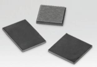
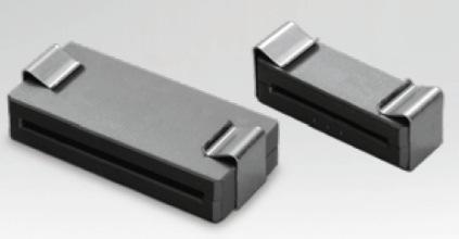
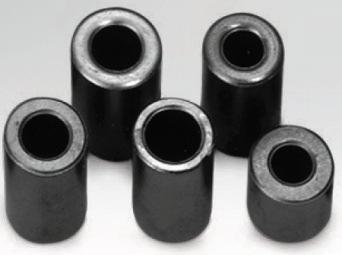
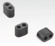
CABLE SHIELDING CHO-SORB EMI Ferrites
 BLE SHIELING HO-SORB EMI Ferrites HO-SORB EMI Ferrites ost effective HO-SORB EMI ferrites reduce conducted emissions and ES susceptibility on signal lines and power cables without affecting data transmission.
Designing Your EMI Filter
 The Engineer s Guide to Designing Your EMI Filter TABLE OF CONTENTS Introduction Filter Classifications Why Do We Need EMI Filters Filter Configurations 2 2 3 3 How to Determine Which Configuration to
IS31LT3360 AIC DEMO BOARD GUIDE
 DESCRIPTION The ISLT6 is a continuous mode inductive step-down converter, designed for driving a single LED or multiple series connected efficiently from a voltage source higher than the LED voltage. The
Demo Circuit DC550A Quick Start Guide.
 May 12, 2004 Demo Circuit DC550A. Introduction Demo circuit DC550A demonstrates operation of the LT5514 IC, a DC-850MHz bandwidth open loop transconductance amplifier with high impedance open collector
Real World Application of Filtering
 Real World Application of Filtering COPYRIGHT NOTICE: JASTECH EMC CONSULTING, LLC 2001 reproduction or translation in any form of any part of this work is prohibited unless written permission is obtained
Using a Linear Transistor Model for RF Amplifier Design
 Application Note AN12070 Rev. 0, 03/2018 Using a Linear Transistor Model for RF Amplifier Design Introduction The fundamental task of a power amplifier designer is to design the matching structures necessary
Supertex inc. HV748DB1 HV748 ±75V 1.25A Ultrasound Pulser Demoboard
 HV78DB HV78 ±75V.5A Ultrasound Pulser Demoboard Introduction The HV78 is a monolithic -channel, high speed, high voltage, ultrasound transmitter pulser. This integrated, high performance circuit is in
1. Explanation of Product Number
 ISM Band 915/868MHz Chip ntenna 1. Explanation of Product Number R 0 2 L P F C 0 1 R 0 0 2 (1) (2) (3) (4) (5) (6) Product Code: (1) Dimensions: 02: 12.5x2.5x0.9(mm) (2) Polarization: L: linear polarization
EUA2011A. Low EMI, Ultra-Low Distortion, 2.5-W Mono Filterless Class-D Audio Power Amplifier DESCRIPTION FEATURES APPLICATIONS
 Low EMI, Ultra-Low Distortion, 2.5-W Mono Filterless Class-D Audio Power Amplifier DESCRIPTION The EUA2011A is a high efficiency, 2.5W mono class-d audio power amplifier. A new developed filterless PWM
Freescale Semiconductor, I
 nc. SEMICONDUCTOR APPLICATION NOTE Order this document by AN955/D Prepared by: Ken Dufour Motorola Power Products Division INTRODUCTION This application note describes a two stage, 30 watt VHF amplifier
Lecture 2 Analog circuits. Seeing the light..
 Lecture 2 Analog circuits Seeing the light.. I t IR light V1 9V +V IR detection Noise sources: Electrical (60Hz, 120Hz, 180Hz.) Other electrical IR from lights IR from cameras (autofocus) Visible light
Standard Antennas. Bluetooth/Wi-Fi Antennas. Cellular Antennas. Ultra Wide Band (UWB) Antennas. GNSS Antennas
 Antennas. GNSS Antennas") Standard Antennas Standard Antennas Bluetooth/Wi-Fi Antennas 146153-2.4/5 GHz Balanced Flexible Antenna 146187-2.4/5 GHz Balanced PCB Antenna 204281-2.4/5 GHz Balanced Flexible Antenna side-fed cable 146175-2.4/5
Standard Antennas Standard Antennas Bluetooth/Wi-Fi Antennas 146153-2.4/5 GHz Balanced Flexible Antenna 146187-2.4/5 GHz Balanced PCB Antenna 204281-2.4/5 GHz Balanced Flexible Antenna side-fed cable 146175-2.4/5
Power Supply Rejection Ratio Measurement
 Power Supply Rejection Ratio Measurement Using the Bode 100 and the Picotest J2120A Line Injector www.telesplicing.com.tw +886-2-27053146 sales@telesplicing.com.tw Page 2 of 10 Table of Contents 1 EXECUTIVE
Laboratory 4: Amplification, Impedance, and Frequency Response
 ES 3: Introduction to Electrical Systems Laboratory 4: Amplification, Impedance, and Frequency Response I. GOALS: In this laboratory, you will build an audio amplifier using an LM386 integrated circuit.
DO IT YOURSELF LOW-COST DIRECTIONAL COUPLERS
 / AN-30-001 Application Note on DO IT YOURSELF LOW-COST DIRECTIONAL COUPLERS Radha Setty Weiping Zheng Mini-Circuits Engineering Department, P.O. Box 350166, Brooklyn, NY 11235 AN-30-001 Rev.: A M150261
EFFECT OF SHIELDING ON CABLE RF INGRESS MEASUREMENTS LARRY COHEN
 EFFECT OF SHIELDING ON CABLE RF INGRESS MEASUREMENTS LARRY COHEN OVERVIEW Purpose: Examine the common-mode and differential RF ingress levels of 4-pair UTP, F/UTP, and F/FTP cables at an (RJ45) MDI port
Low Value Impedance Measurement using the Voltage / Current Method
 Low Value Impedance Measurement using the Voltage / Current Method By Florian Hämmerle & Tobias Schuster 2017 Omicron Lab V2.2 Visit www.omicron-lab.com for more information. Contact support@omicron-lab.com
Demo Board LMH7220 High Speed LVDS Comparator
 Demo Board LMH7220 High Speed LVDS Comparator General Description This board is designed to demonstrate the LMH7220 high speed comparator with LVDS output. The board consists of two parts; one part acts
Current Probe. Inspector Data Sheet. Low-noise, high quality measurement signal for side channel acquisition on embedded devices.
 Inspector Data Sheet Low-noise, high quality measurement signal for side channel acquisition on embedded devices. Riscure Version 1c.1 1/5 Introduction Measuring the power consumption of embedded technology
Chapter 2. The Fundamentals of Electronics: A Review
 Chapter 2 The Fundamentals of Electronics: A Review Topics Covered 2-1: Gain, Attenuation, and Decibels 2-2: Tuned Circuits 2-3: Filters 2-4: Fourier Theory 2-1: Gain, Attenuation, and Decibels Most circuits