USER'S MANUAL FX-1PG/FX2N-1PG PULSE GENERATOR UNIT
|
|
|
- Cameron Beasley
- 6 years ago
- Views:
Transcription

1 USER'S MANUAL FX-1PG/FX2N-1PG PULSE GENERATOR UNIT
2 Foreword This manual contains text, diagrams and explanations which will guide the reader in the correct installation and operation of the FX-1PG/FX2N-1PG pulse generator unit. It should be read and understood before attempting to install or use the unit. Further information can be found in the FX PROGRAMMING MANUAL(II), FX/FX2N series hardware manuals. If in doubt at any stage of the installation of FX-1PG/FX2N-1PG pulse generator unit always consult a professional electrical engineer who is qualified and trained to the local and national standards that applies to the installation site. If in doubt about the operation or use of FX-1PG/FX2N-1PG pulse generator unit please consult your local Mitsubishi Electric representative. This manual is subject to change without notice.
3 FX-1PG/FX2N-1PG PULSE GENERATOR UNIT USER'S MANUAL Manual number : JY992D65301 Manual revision : N Date : April 2015 This manual confers no industrial property rights or any rights of any other kind, nor does it confer any patent licenses. Mitsubishi Electric Corporation cannot be held responsible for any problems involving industrial property rights which may occur as a result of using the contents noted in this manual.
4 Guidelines for the Safety of the User and Protection of the FX-1PG/FX2N-1PG pulse generator unit. This manual provides information for the use of the FX-1PG/FX2N-1PG pulse generator unit. The manual has been written to be used by trained and competent personnel. The definition of such a person or persons is as follows: a) Any engineer who is responsible for the planning, design and construction of automatic equipment using the product associated with this manual, should be of a competent nature, trained and qualified to the local and national standards required to fulfill that role. These engineers should be fully aware of all aspects of safety with regards to automated equipment. b) Any commissioning or service engineer must be of a competent nature, trained and qualified to the local and national standards required to fulfill that job. These engineers should also be trained in the use and maintenance of the completed product. This includes being completely familiar with all associated documentation for said product. All maintenance should be carried out in accordance with established safety practices. c) All operators of the completed equipment (see Note) should be trained to use this product in a safe manner in compliance to established safety practices. The operators should also be familiar with documentation which is associated with the actual operation of the completed equipment. Note : The term completed equipment refers to a third party constructed device which contains or uses the product associated with this manual. i
5 Notes on the Symbols Used in this Manual At various times throughout this manual certain symbols will be used to highlight points which are intended to ensure the users personal safety and protect the integrity of equipment. Whenever any of the following symbols are encountered its associated note must be read and understood. Each of the symbols used will now be listed with a brief description of its meaning. Hardware Warnings 1) Indicates that the identified danger WILL cause physical and property damage. 2) Indicates that the identified danger could POSSIBLY cause physical and property damage. 3) Indicates a point of further interest or further explanation. Software Warnings 4) Indicates special care must be taken when using this element of software. 5) Indicates a special point which the user of the associate software element should be aware. 6) Indicates a point of interest or further explanation. ii
6 CONTENTS 1. INTRODUCTION Introduction OUTSIDE DIMENSIONS Outside Dimensions TERMINAL ARRANGEMENT Terminal Arrangement and LED Indication SPECIFICATIONS Specifications BFM LIST BFM List System of Units and Parameter Setting Speed Data and Position Data Position Data, Home Position and Current Position Operation Command Status and Error Codes OUTLINE OF OPERATION MODES JOG Operation and Machine Home Position Return Operation DOG Switch Overshoot Detection Home Return Positioning Method Undershoot Detection Home Return Positioning Method Home Position Return Operation iii
7 6.2 Single-Speed Positioning Operation and Interrupt Single-Speed Positioning Operation Two-Speed Positioning Operation and External Command Positioning Operation Variable Speed Operation Common Matter for Operation Modes Connection of DOG and STOP Inputs and Handling of Limit Switches for Limit Detection Various Operation Modes and Buffer Memory Setting OUTLINE OF FROM/TO INSTRUCTION (PC) FROM/TO Instruction I/O SPECIFICATIONS I/O Specifications EXTERNAL CONNECTION EXAMPLES Example of Connection Between FX-1PG and Stepper Motor Example of Connection Between FX2N-1PG and Stepper Motor Example of External Connection (MR-C Servo Amplifier) Example of External Connection (MR-J Servo Amplifier) Example of External Connection (MR-J2(S) Servo Amplifier) Example of External Connection (MR-H Servo Amplifier) Example of External Connection (MR-J3 Servo Amplifier) Example of External Connection (MR-JN Servo Amplifier) Example of External Connection (MR-J4 Servo Amplifier) PROGRAM EXAMPLES The reciprocation by single-speed positioning iv
8 11.DIAGNOSTICS Preliminary Checks and Error Indication v
9 1. INTRODUCTION 1.1 Introduction INTRODUCTION The FX-1PG/FX2N-1PG pulse generator unit (hereinafter referred to as PGU ) performs simple positioning of an independent axis (not interpolation control between multiple axes) by supplying a prescribed quantity of pulses (100 khz maximum) to drive amplifiers for servo or stepper motors. The FX-1PG is attached as an extension to the FX/FX2C series programmable controller (hereinafter referred to as PC ), and the FX2N-1PG is attached as an extension to the FX2N/FX2NC/FX3U/FX3UC series PC. Each PGU functions as a special block which transfers data with the PC using the FROM/TO instructions, and occupies 8 points of inputs or outputs. For the number of connectable PGU to the PLC, refer to the manual of the PLC to be connected. The PGU provides connection terminals for positioning operations that require high-velocity responses as well as those used for pulse train outputs. Other general I/O operations are controlled via the PLC. Because all the program for positioning control are executed in the PC, the PGU does not require dedicated teaching panel, etc. As the programming tools for the PLC, the following devices are available without modification. GOT, Data access units can be connected to the PLC to set or display the positioning data. 1 FX/FX2C/FX2N/FX2NC/ FX3U/FX3UC Series PC PGU FX-1PG/ FX2N-1PG Programming tools GOT, Data access units FROM TO Pulse train High-velocity I/O Control panel Machine Drive amplifier Servo motor or stepper motor Control I/O 1-1
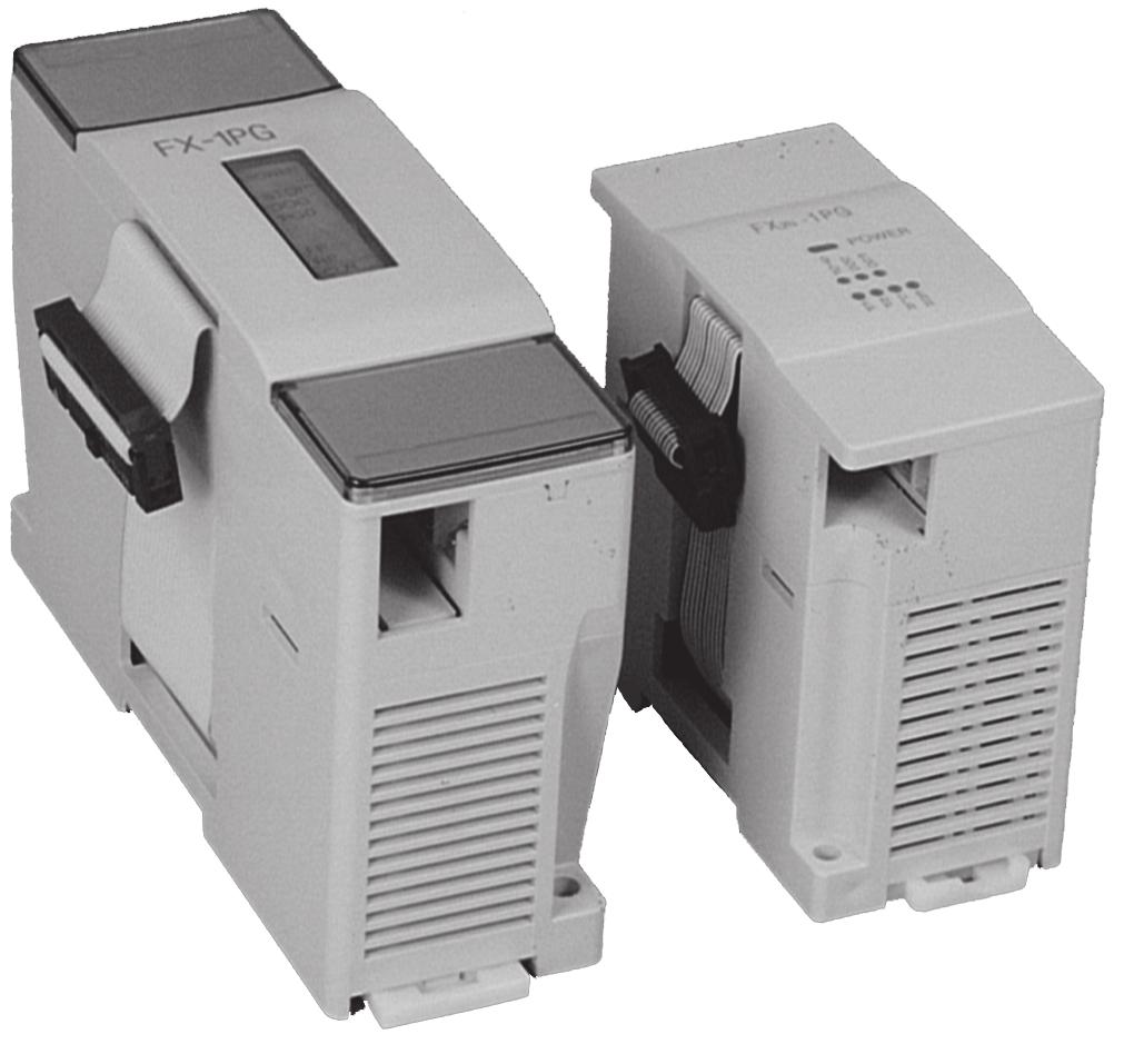
10 140(5.51) 125(4.92) Mounting holes 2 FX-1PG/FX2N-1PG PULSE GENERATOR UNIT OUTSIDE DIMENSIONS 2. OUTSIDE DIMENSIONS 2.1 Outside Dimensions FX-1PG Attachment groove 35mm Wide DIN rail 10(0.39) 95(3.74) Mounting holes 35(1.38) 45(1.77) Mass (Weight): Approx. 0.3 kg (0.66 lbs) Terminal screw: M3.5 Terminal screw tightening torque: 0.5 to 0.8 N m Do not tighten terminal screws with a torque outside the above-mentioned range. Failure to do so may cause equipment failures or malfunctions. Applicable terminals: 6.8(0.27) or less 6.8(0.27) or less For M3.5 Accessories: No. labels for special modules Dimensions : mm (inch) The PGU is installed to the right side of a main unit or an extension unit of an FX/FX2C Series PC or of an other extension block. The PGU can be installed using a DIN rail (DIN 46277, Width: 35 mm) or directly installed using M4 screws. (For the details, refer to the handy manual packed together with the main unit.) 2-1
11 90(3.51) 80(3.12) FX-1PG/FX2N-1PG PULSE GENERATOR UNIT FX2N-1PG OUTSIDE DIMENSIONS 2 Mass (Weight): Approx. 0.2 kg (0.44 lbs) Terminal screw: M3 Attachment groove 35mm Wide DIN rail 9(0.35) 4(0.16) 87(3.39) 43(1.68) Terminal screw tightening torque: 0.5 to 0.8 N m Do not tighten terminal screws with a torque outside the above-mentioned range. Failure to do so may cause equipment failures or malfunctions. Applicable terminals: 6.2(0.24) or less 6.2(0.24) or less For M3 Accessories: No. labels for special modules Dimensions : mm (inch) The PGU is installed to the right side of a main unit or an extension unit of an FX2N/FX2NC/FX3U/FX3UC Series PLC or of an other extension block. For details, refer to the main unit manual. The PGU can be installed using a DIN rail (DIN 46277, Width: 35 mm) or directly installed using M4 screws. 2-2
12 3 FX-1PG/FX2N-1PG PULSE GENERATOR UNIT TERMINAL ARRANGEMENT 3. TERMINAL ARRANGEMENT 3.1 Terminal Arrangement and LED Indication FX-1PG FX2N-1PG <LED allocation> Common between FX-1PG and FX2N-1PG POWER STOP DOG PG0 Indicates power status of PGU. Lighted when 5 V is supplied from PLC. Lighted when the stop command is input to the STOP terminal. Lighted when DOG input is entered. Lighted when zero point signal is entered. FP RP Flashes when forward pulse or pulses are output. Flashes when reverse pulse or direction are output. Output format can be modified using BFM #3 b8. CLR ERR Lighted when CLR signal is output. Flashes when error has occurred. Start command is not accepted when error has occurred. 3-1
13 <Terminal allocation> FX-1PG FX2N-1PG Function SG - Signal ground. Short-circuit it to SG terminal of PC. TERMINAL ARRANGEMENT STOP DECELERATION STOP input. Can function as stop command input in external command operation mode. Offers following different functions depending on operation mode. DOG Machine home position return operation: NEAR POINT SIGNAL input Interrupt single-speed operation: INTERRUPT input External command operation: DECELERATION START input S/S 24V DC power terminal for STOP input and DOG input Connected to sensor power supply of PC or external power supply. PG0+ Power terminal for zero point signal Connected to servo amplifier or external power supply (5 to 24V DC, 20 ma or less) PG0- Enters zero point signal from drive unit or servo amplifier. Response pulse width: 4 s or more VH - Power terminal for pulse output (supplied from servo amplifier or external unit) 24V DC±10% Current consumption: 15 ma VL - Power terminal for pulse output (supplied from servo amplifier or external unit) 5 to 15V DC Current consumption: 20 ma - VIN Power terminal for pulse output (supplied from servo amplifier or external unit) 5 to 24V DC, 35 ma or less FP0 - Pull-up resistance. Connected to VH or VL. FP Terminal which outputs forward pulse or pulses. 100 khz, 20 ma or less (5 to 24V DC) COM0 Common terminal for pulse output RP Terminal which outputs reverse pulse or direction. 100 khz, 20 ma or less (5 to 24V DC) RP0 - Pull-up resistance. Connected to VH or VL. COM1 Common terminal for CLR output CLR Output for clearing deviation counter. 5 to 24V DC, 20 ma or less Output pulse width: 20 ms (Output when return to home position is completed or LIMIT SWITCH input is given.) Spare terminal. Shall not be used a relay terminal
14 4 FX-1PG/FX2N-1PG PULSE GENERATOR UNIT SPECIFICATIONS 4. SPECIFICATIONS 4.1 Specifications <General specifications> The general specifications are equivalent to those of the main unit of the FX PC. (For the details, refer to the handy manual packed together with the main unit.) 4-1
15 <Performance specifications> Item Specifications SPECIFICATIONS 4 Drive power supply 1) +24V (for input signals) 2) +5V (for internal control) 3) For pulse output : 24V DC ±10% Current consumption: 40 ma or less Supplied from external power supply or 24+ output of PC. : 5V DC, 55 ma Supplied from PC via extension cable. : 5V to 24V DC current consumption: 35mA or less Number of I/O points occupied Number of control axes Command speed Setting pulse Pulse output format External I/O Communication with PC 8 input or output points of PC for each PGU 1 (A single PC can control independent 8 axes maximum.) Operations are enabled at pulse speed of 10 Hz to 100 khz. Command unit can be selected among Hz. cm/min, 10 deg/min and inch/min. 0 to ±999,999 Absolute position specification or relative travel specification can be selected. Command unit can be selected among pulse, μm, mdeg and 10-4 inch. Multiplication of 10 0, 10 1, 10 2 or 10 3 can be set for position data. Forward (FP) and reverse (RP) pulse or pulse (PLS) with direction (DIR) can be selected. Open collector and transistor output. 5 to 24V DC, 20 ma or less Photocoupler insulation and LED operation indication are offered for every point. 3 input points: (STOP/DOG) 24V DC, 7 ma and (PG0*1) 24V DC, 20 ma (For details, refer to Section 8.1.) 3 output points (FP/RP/CLR): 5 to 24V DC, 20 ma or less (For details, refer to Section 8.1.) 16-bit RAM (without battery backup) buffer memories (BFMs) #0 to #31 are built in PGU. Data communication with PC is performed using FROM/TO instructions, etc. (For details, refer to Section 7.1) 32-bit data is processed by combining two BFMs. (For details, refer to Section 5.1.) *1 One zero point signal PG0 is entered by flowing the current from the PG0+ terminal to the PG0- terminal. 4-2
16 5 5. BFM LIST 5.1 BFM List FX-1PG/FX2N-1PG PULSE GENERATOR UNIT 5-1 BFM LIST *1 Unit is m/r, mdeg/r or 10-4 inch/r. *2 Unit is PLS, m/r, mdeg/r or 10-4 inch depending on the system of units set in the BFM #3 b1 and b0. BFM No. Higher 16 bits Lower 16 bits b15 b14 b13 b12 b11 b10 b9 b8 b7 b6 *4 #0 Pulse rate A 1 to 32,767 PLS/REV (Pulse/Revolution) *4 #2 #1 Feed rate B 1 to 999,999 *1 *4 #3 Home STOP Pulse STOP Count start DOG input position Rotation input mode input timing polarity return direction output polarity format direction *4 #5 #4 Maximum speed Vmax 10 to 100,000 Hz *4 #6 Bias speed Vbia 0 to 10,000 Hz #8 #7 JOG speed VJOG 10 to 100,000 Hz #10 #9 Home position return speed (high speed) VRT 10 to 100,000 Hz #11 Home position return speed (creep speed) VCR 10 to 10,000 Hz #12 Number of zero point signals for home position return N 0 to 32,767 PLS #14 #13 Home position HP 0 to ±999,999 *2 *4 #15 Acceleration/deceleration time Ta 50 to 5,000 ms #16 Reserved #18 #17 Set position (I) P(I) 0 to ±999,999 *2 #20 #19 Operating speed (I) V(I) 10 to 100,000 Hz #22 #21 Set position (II) P(II) 0 to ±999,999 *2 #24 #23 Operating speed (II) V(II) 10 to 100,000 Hz Variable External Interrupt Single Two speed *3 speed command positioning single speed speed #25 operation positioning positioning positioning start start start start start Relative / absolute position Home position return start #27 #26 Current position CP Automatic writing -2,147,483,648 to 2,147,483,647 #28 Current Positioning position completed Error flag flag value overflow #29 Error code Error code is automatically written when error has occurred. #30 Model code 5110" is automatically written. #31 Reserved
17 BFM LIST *3 Only one bit among the BFM #25 b6 to b4 and b12 to b8 can be turned on. If two or more bits among them are turned on, no operation is performed. *4 When data is written into the BFMs #0, #1, #2, #3, #4, #5, #6 and #15, data is calculated inside the PGU during the first positioning operation. To save this processing time (500 ms maximum). b5 b4 b3 b2 b1 b0 Initial value: 2,000 PLS/REV Initial value: 1,000 PLS/REV Position data multiplication 10 0 to 10 3 Initial value: 100,000 Hz Initial value: 0 Hz Initial value: 10,000 Hz Initial value: 50,000 Hz Initial value: 1,000 Hz Initial value: 10 PLS Initial value: 0 Initial value: 100 ms Initial value: 0 Initial value: 10 Hz Initial value: 0 Initial value: 10 Hz JOG operation JOG+ operation Reverse pulse stop Forward pulse stop System of units [Motor system, Machine system, Combined system] STOP Error reset R: For read W: For write R/W R/W 5 When the power of the PGU is turned off, the BFM data is cleared. When the power of the PGU is turned on, the initial values are entered to the BFMs. The BFMs #0, #1 and #2 are neglected when the BFM #3 (b1, b0) is set to the motor system. The instruction data format (TO/FROM, DTO/DFROM, etc.) must match the target BFM's data format. When the instruction data format does not match the target BFM's data format (16-bit/32- bit), the PGU will not read/write data to the BFM properly, whereas no error will appear. This may cause an operation error to the positioning. < Reading of 32-bit data > D FROM K 0 K 26 D 0 K 1 32-bit instruction... Current position (32-bit data) FROM K 0 K 26 D 0 K 1... PG0 input ON DOG input ON STOP input ON Home position return completed Reverse rotation/ Forward rotation Ready R 16-bit instruction Current position (32-bit data) At BFM #19 and #20, variable speed operation and external command positioning operation, can set a negative value. (-10 to -100,000 Hz) 5-2
18 5 FX-1PG/FX2N-1PG PULSE GENERATOR UNIT 5.2 System of Units and Parameter Setting [ BFM #0 ] Pulse rate A: 1 to 32, 767 P/R This is the number of input pulses required by the amplifier to rotate the motor by 1 revolution. It is not the number of encoder pulses per revolution of the motor. (The pulse rate becomes a different value in accordance with the electronic gear ratio.) The BFM #0 is not required to be set when the motor system of units described later is selected. [ BFMs #2 and #1 ] Feed rate B1 (distance specification) = 1 to 999,999 m/r B2 (angle specification) = 1 to 999,999 mdeg/r B3 (distance specification) = 1 to 999,999x10-4 inch/r This is the machine travel B while the motor rotates by 1 revolution. Set either one among B1, B2 and B3 in accordance with the unit among m/r, mdeg/r and 10-4 inch/r suitable to the application. The BFMs #2 and #1 are not required to be set when the motor system of units described later is selected. [ BFM #3 ] Parameters (b0 to b15) Set bits 0 to 15 as follows. 1) System of units (b1, b0) b1 b0 System of units Remarks *1 Offers the same operation. BFM LIST 0 0 Motor system Units based on pulses 0 1 Machine system Units based on lengths and angles *1 1 0 *1 1 1 Position data*2 Speed data*3 Combined system Units based on lengths and angles for position units based on Hz for speed The table below shows the units for position and speed in accordance with the setting of the BFMs #2 and #1 (feed rate). Selection of feed rate Motor system Combined system B1 PLS μm B2 PLS mdeg B3 PLS 10-4 inch Machine system B1 Hz cm/min B2 Hz 10deg/min B3 Hz inch/min *2 Position data: HP, P(I), P(II), CP *3 Speed data: Vmax, Vbia, VJOG, VRT, V(I), V(II) 5-3
19 2) Multiplication of position data (b5, b4) b5 b4 Multiplication The position data HP, P(I), P(II) and CP will be multiplied by the value shown in the table on the left Example: When the value of the set position P(I) (BFMs #18 and #17) is 123 and the BFM #3 (b5, b4) is (1, 1), the actual position (or travel) becomes as follows: Motor system of units = 123,000 (pulses) Machine system of units = 123,000 ( m, mdeg, 10-4 inch) Combined system of units = 123 (mm, deg, 10-1 inch) 3) Pulse output format (b8) The pulse output terminals FP and RP of the PGU change as follows in accordance with the setting (0 or 1) of b8. When b8 = 0: Forward pulse (FP) and reverse pulse FP RP Reverse pulse Forward pulse OFF ON OFF ON BFM LIST When b8 = 1: Pulse (PLS) with direction (DIR) FP (PLS) RP (DIR) Forward Reverse OFF ON OFF ON 5 4) Rotation direction (b9) When b9 = 0: The current position (CP) value increases with a forward pulse (FP). When b9 = 1: The current position (CP) value decreases with a forward pulse (FP). This bit is used for the initial setting. The rotation direction is not required to be changed in every actual operation. 5) Home position return direction (b10) When b10 = 0:The current position (CP) value decreases during return to the home position. When b10 = 1:The current position (CP) value increases during return to the home position. 6) DOG input polarity (b12) When b12 = 0:The DOG (near point signal) input is turned on when the workpiece is coming near the home position. When b12 = 1:The DOG (near point signal) input is turned off when the workpiece is coming near the home position. 5-4
20 5 FX-1PG/FX2N-1PG PULSE GENERATOR UNIT 7) Count start point (b13) See Sections to This bit specifies the point at which counting of zero point signals is started. When b13 = 0:Counting of zero point signals is started when the DOG input is given (when DOG input is turned on if b12 is set to 0 or when DOG input is turned off if b12 is set to 1). When b13 =1: Counting of zero point signals is started when the DOG input is given once, then stopped. BFM LIST 9) STOP input mode (b15) When b15 = 0:The operation is interrupted when the stop command is given (from the PGU or the PC) during operation, then the operation for the remaining distance is restarted when the restart command is given. The Jog drive begins again when the stop command is turned off from turning on when the Jog command has been turned on. * However, if any BFMs (except #25) is rewritten while operation is interrupted by the stop command, the operation for the remaining distance will not be 8) STOP input polarity (b14) performed. Write the BFMs (except #25) by pulse operation. When the STOP input mode takes up When b14 = 0:The operation is stopped when the input the remainder of the drive operation, please set the is turned on (OFF during operation). maximum speed and operating speed as the same When b14 = 1:The operation is stopped when the input value. is turned off (ON during operation). When b15 = 1:The operation for the remaining distance This polarity changeover is valid exclusively for the is not performed, but the next positioning STOP input in the PGU. is performed. The Jog drive begins again when the stop command is turned off from turning on when the Jog command has been < Note> BFM #3 turned on. b15 b14 b13 b12 b11 b10 b9 b8 b7 b6 b5 b4 b3 b2 b1 b0 Stop input mode Stop input polarity Count start point Polarity of the DOG input 0 Home position return direction Rotation direction Pulse format 0 0 Multiplication of position data 0 0 Unit system Write hexadecimal H in BFM # 3 in accordance with the 0 and 1 status of each bit. Set b2, b3, b6, b7 and b11 to
21 5.3 Speed Data and Position Data [ BFMs #5 and #4 ] Maximum speed Vmax Motor system and combined system: 10 to 100,000 Hz Machine system: 1 to153,000 This is the maximum speed. Make sure that the bias speed (BFM #6), the JOG speed (BFMs #7 and #8), the home position return speed (BFMs #9 and #10), the creep speed (BFM #11), the operating speed (I) (BFMs #19 and #20) and the operating speed (II) (BFMs #23 and #24) are set respectively to a value equivalent to or less than the maximum speed. The degree of acceleration/deceleration is determined by this maximum speed, the bias speed (BFM #6) and the acceleration/deceleration time (BFM #15). [ BFM #6 ] Bias speed Vbia Motor system and combined system: 0 to 10,000 Hz Machine system: 0 to15,300 This is the bias speed at time of start. When the FX(2N)-1PG and the stepper motor are used together, set a value while taking the resonance area and the self-start frequency of the stepper motor into account. [ BFMs #8 and #7 ] JOG speed VJOG Motor system and combined system: 10 to 100,000 Hz Machine system: 1 to153,000 This is the speed for manual forward/reverse (JOG+/JOG-). BFM LIST Set a value between the bias speed Vbia and the maximum speed Vmax. 5 [ BFMs #10 and #9 ] Home position return speed (high speed) VRT Motor system and combined system: 10 to 100,000 Hz Machine system: 1 to153,000 This is the speed (high speed) for returning to the machine home position. Set a value between the bias speed Vbia and the maximum speed Vmax. [ BFM #11 ] Home position return speed (creep) VCR Motor system and combined system: 10 to 10,000 Hz Machine system: 1 to15,300 This is the speed (extremely slow speed) after the near point signal (DOG) for returning to the machine home position. It is the speed immediately before stopping in the machine home position. It is recommended to set it as slow as possible so that the precision of the home position becomes better. [ BFM #12 ] Number of zero point signals for home position return N 0 to 32,767 PLS This is the number of zero point signals counted for returning to the machine home position. When the zero point signal is not used and the machine should be stopped immediately by only the DOG input, set the BFM #12 to 0. However, pay rigid 5-6
22 5 FX-1PG/FX2N-1PG PULSE GENERATOR UNIT attention so that the machine is not damaged when it is immediately stopped from high-speed operation. [ BFMs#14 and #13 ] Home position HP Motor system: 0 to ±999,999 PLS Machine system and combined system: 0 to ±999,999 This is the home position used for returning to the machine home position. When the home position return operation is completed, the value set here is written to the current position (BFMs #26 and #27). [ BFM #15 ] Acceleration/deceleration time Ta 50 to 5,000 ms This is the time between the bias speed (BFM #6) and the maximum speed (BFMs #5 and #4). The degree of acceleration/deceleration is determined by the maximum speed, the bias speed and the acceleration/deceleration time. When bias speed (BFM #6) is set Acceleration/ deceleration time (BFM #15) Maximum speed (BFMs #5 and #4) They cannot be set separately. Same value is used. Acceleration/ deceleration time (BFM #15) BFM LIST [ BFMs#18 and #17 ] Set position (I) P(I) Motor system: 0 to ±999,999 PLS Machine system and combined system: 0 to ±999,999 This is the target position or the travel distance for operation. When the absolute position is used, the rotation direction is determined in accordance with the absolute value of the set position based on the current position (BFMs #26 and #27). When the relative position is used, the rotation direction is determined by the sign of the set position. [ BFMs #20 and #19 ] Operating speed (I) V(I) Motor system and combined system: 10 to 100,000 Hz Machine system: 1 to 153,000 This is the actual operating speed within the range between the bias speed Vbia and the maximum speed Vmax. In variable speed operation and external command positioning operation, forward rotation or reverse rotation is performed in accordance with the sign (positive or negative) of this set speed. [ BFMs #22 and #21 ] Set position (II) P(II) Motor system: 0 to ±999,999 PLS Machine system and combined system: 0 to ±999,999 This is the set position for the second speed in twospeed positioning operation. 5-7
23 BFM LIST 5 [ BFMs #24 and #23 ] Operating speed (II) V(II) Motor system and combined system: 10 to 100,000 Hz Machine system: 1 to 153,000 This is the second operating speed in two-speed positioning operation within the range between the bias speed Vbia and the maximum speed Vmax. [ BFMs #27 and #26 ] Current position CP Motor system:-2,147,483,648 to +2,147,483,647 PLS Machine system and combined system: -2,147,483,648 to +2,147,483,647 The current position data is automatically written here. When the value set here is read by the PC for monitoring, make sure to read it in the unit of 32 bits. D FROM K 0 K 26 D 0 K 1 32-bit instruction < Conversion of system of units > The following relationship is present between the motor system of units and the machine system of units. They are automatically converted each other. Speed command cm/min, 10deg/min, inch/min = Speed command (Hz) 60 A indicates the pulse rate. B1 to B3 indicate the feed rate. PPS indicates the pulses per second. When setting the speed data using the machine system of units, make sure that the value converted into pulses is within the range determined for the motor system and the combined system (Hz). < Stepwise speed command value > The frequency f of the pulse generated in the PGU is stepwise as follows. A 10 4 B1, B2 or B3 f = n 10 6 = 10 to 100,000 Hz Where, n: Integer in range of 40 to 400,000 For example, in the case of n = 40, f = 100,000 Hz in the case of n = 41, f = 97,560 Hz Any pulse whose frequency is between the two values above cannot be generated. 5-8
24 5 FX-1PG/FX2N-1PG PULSE GENERATOR UNIT BFM LIST 5.4 Position Data, Home Position and Current Position Speed The position data includes the following: HP: Home position, P(I): Set position (I), P(II): Set position (II) and CP: Current position The unit and the multiplication of each item are described in Section 5.2. When the operation of returning to the machine home position is completed, the home position HP (BFMs #14 and #13) value is automatically written to the current position CP (BFMs #27 and #26). The figure below shows the CP value when the home position HP is PG0 DOG The current position (CP) value increases or decreases in accordance with the forward/reverse pulse. < Error in command between the machine system of units and the combined system of units> When the pulse rate of the BFM #0 (#2, #1) is supposed the pulse rate as A, the feed rate as B and the relative travel distance as C, the value C (A/B) indicates the pulse quantity which should be generated by the PGU. Even if the value (A/B) is not an integer, error is not generated in the command if the value C (A/B) is an integer. However, if the value C (A/B) is not an integer, accumulated error is generated in the current position when relative movement is repeated. When the absolute is used for operation, an error less than 1 pulse may be generated by counting fractions over 1/2 as one and disregarding the rest, but accumulated error is not generated. When the motor system of units is used, such an accumulated error is not generated. Machine home position CP=HP= 100 CP=0 The set positions P(I) and P(II) can be treated as absolute positions (distance from the current position CP = 0) or relative positions (travel from the current stop position) as described later. 5-9
25 5.5 Operation Command [ BFM #25 ] Operation command (b0 to b11, b12) After data is written to the BFMs #0 to #24, write the BFM #25 (b0 to b12) as follows. [b0] When b0 = 1: Error reset The error flag (BFM #28 b7) described later is reset. When the error occurs, the positioning completion signal (BFM #28 b8) is reset. [b1] When b1 = 0 1: Stop This bit functions in the same way with the STOP input in the PGU, but the stop operation can be performed from the sequence program in the PC. However, if this bit is changed from 0 to 1 before the STOP input is given in the PGU in the external command positioning mode, the machine is decelerated and stopped. [b2] When b2 = 1: Forward pulse stop The forward pulse is immediate stopped in the forward limit position. [b3] When b3 = 1: Reverse pulse stop The reverse pulse is immediate stopped in the reverse limit position. [b4] When b4 = 1: JOG+ operation When b4 continues to be 1 for less than 300 ms, one forward pulse is generated. When b4 continues to be 1 for 300 ms or more, continuous forward pulses are generated. BFM LIST 5 [b5] When b5 = 1: JOG- operation When b5 continues to be 1 for less than 300 ms, one reverse pulse is generated. When b5 continues to be 1 for 300 ms or more, continuous reverse pulses are generated. [b6] When b6 = 0 1: Home position return start The machine starts to return to the home position, and is stopped at the machine home position when the DOG input (near point signal) or the PG0 (zero point signal) is given. [b7] When b7 = 0: Absolute position When b7 = 1: Relative position The relative or absolute position is specified in accordance with the b7 status (1 or 0). (This bit is valid while operation is performed using b8, b9 or b10.) [b8] When b8 = 0 1: Single-speed positioning operation start Single-speed positioning operation is performed. For the details, see Section 6.2. [b9] When b9 = 0 1: Interrupt single-speed positioning operation start Interrupt single-speed positioning operation is performed. For the details, see Section 6.2. [b10] When b10 = 0 1: Two-speed positioning operation start Two-speed positioning operation is performed. For the details, see Section
26 5 FX-1PG/FX2N-1PG PULSE GENERATOR UNIT [b11] When b11 = 0 1: External command positioning operation start External command positioning operation is performed. The rotation direction is determined by the sign of the speed command. For the details, see Section 6.3. [b12] When b12 = 1: Variable speed operation Variable speed operation is performed. For the details, see Section 6.4. BFM LIST < Operation command data transfer method > X000 X001 X002 X003 X004 X005 X006 Start X007 M8000 RUN monitor (Normally closed contact) (Normally closed contact) Set only one of them to ON. M8000 M0 M1 M2 M3 M4 M5 M6 M7 M8 M9 M10 M11 M12 Error reset Stop command Forward pulse stop Reverse pulse stop Jog+ operation Jog- operation Home position return start Relative/absolute position Single-speed positioning Interrupt singlespeed positioning Two-speed positioning External command positioning Variable speed operation TO K 0 K25 K4M0 K 1 (M15~M 0) BFM #25 (b15~b 0) 5-11
27 BFM LIST 5 Error can be reset by forcedly turning on/off the peripheral unit. The input X000 does not have to be used. When the data on absence/presence of error and the error code should be saved even after power interrupt, use the auxiliary relays or data registers backed up by the battery. The stop command is generally provided in the PGU, and is also output from the sequence program in the PC. In such a case, the input X001 is not required. In operation which does not require returning to the home position such as inching operation with a constant feed rate, the input X006 is not required. When which one between the relative and absolute positions should be used is always determined, drive the M7 using the M8000 or set the M7 always to OFF. Drive one of the M8 to M12 using the M8000. If two or more of them are turned on, operation is disabled. (See Section 6.4.) As the general start command, create an appropriate sequence using the input X007 to drive the M8 to M12. (See Section 9.1.) The time after the FX(2N)-1PG receives the start command until it generates a pulse is approximately 10 ms usually. However, 500 ms maximum is required for the first operation after the PC starts running or for the first operation after the BFM #0, #1, #2, #3, #4, #5, #6 or #15 is written. The TO instruction is a write instruction from the PC to the BFM. In the example on the left, the PGU is connected as a special unit in the position nearest the main unit. In the program below, the start bit for the operation mode cannot be set to OFF inside the PGU, so operation from the second time and later cannot be performed. Correct it as shown in the right. X000 X001 TO K 0 K25 H0400 K 1 TO K 0 K25 H0400 K 1 X000 X001 M10 M8000 TO K0 K25 K4M0 K1 5-12
28 5 FX-1PG/FX2N-1PG PULSE GENERATOR UNIT 5.6 Status and Error Codes The status information to notify the PC of the PGU status is automatically saved in the BFM #28. Read it into the PC using the FROM instruction. [ BFM #28] Status information (b0 to b8) [b0] When b0 = 0: BUSY When b0 = 1: READY This bit is set to BUSY while the PGU is generating pulses. [b1] When b1 = 0: Reverse rotation When b1 = 1: Forward rotation This bit is set to 1 when operation is started with forward pulse. [b2] When b2 = 0: Home position return unexecuted When b2 = 1: Home position return completed When returning to the home position is completed, b2 is set to 1, and continues to be 1 until the power is turned off. To reset b2, use the program. [ In the FX-1PG manufactured in November, 1993 or later (Serial No. 3Y**** or later), b2 can be reset by the program. In every FX2N-1PG, b2 can be reset by the program. ] Connect b2 in series to the start command. (Program example to reset b2) Write K0" to the BFM #28 (status information) using the TO (P) instruction. By this program, b2 (home position return completed) only in the BFM #28 is reset and rewritten to 0. "Home position return completed" bit reset input TO P K 0 K 28 K 0 K 1 BLK No. BFM No. Written value BFM LIST Number of transfer points [b3] When b3 = 0: STOP input OFF When b3 = 1: STOP input ON [b4] When b4 = 0: DOG input OFF When b4 = 1: DOG input ON [b5] When b5 = 0: PG0 input OFF When b5 = 1: PG0 input ON Any of them represents the ON/OFF status of the PGU input as it is. [b6] When b6 = 1: Current position value overflow The 32-bit data saved in the BFMs (#27 and #26) has overflown. This bit is reset when returning to the home position is completed or the power is turned off. [b7] When b7 = 1: Error flag b7 becomes 1 when an error has occurred in the PGU, and the contents of the error are saved in the BFM #29. This error flag is reset when the BFM #25 b0 becomes 1 or the power is turned off. [b8] When b8 = 0: Positioning started When b8 = 1: Positioning completed b8 is cleared when positioning is started home position return start, or error reset, and set when positioning is completed. b8 is also set when returning to the home position is completed. 5-13
29 Various start commands are accepted exclusively while the BFM #28 b0 is set to 1 (READY). Various data is also accepted exclusively while the BFM #28 b0 is set to 1 (READY). However, the BFM #25 b1 (stop command), the BFM #25 b2 (forward pulse stop) and the BFM #25 b3 (reverse pulse stop) are accepted even while the BFM #28 b0 is set to 0 (BUSY). The data can be read from the PGU to the PC without regard to the setting of the BFM #28 b0. The current position is changed accompanied by generation of pulses even while the BFM #28 b0 is set to 0 (BUSY). BFM LIST < Reading of status information > M8000 FROM K 0 K 28 K3M20 K 1 RUN monitor BFM #28 (b11~b 0) (M31~M20) M20 (READY/BUSY) M21 (Forward rotation/reverse rotation) M22 M23 (STOP input ON/OFF) M24 (DOG input ON/OFF) M25 (Home position return completed/ unexecuted) (PG0 input ON/OFF. However, it may not be turned on or off if PG0 input time is shorter than calculation time.) M26 (Current position value overflow) 5 M27 (Absence/ presence of error) FROM K 0 K 29 D200 K 1 M28 (Positioning completed*) Error code * When a drive amplifier for a stepper motor without the positioning completed output is used, this signal can be used for recognition of positioning completed and the next operation can be started. 5-14
30 5 FX-1PG/FX2N-1PG PULSE GENERATOR UNIT < Error code No. > [ BFM #29 ] The following error code Nos. are saved in the BFM #29. Read and check it when the BFM #28 b7 is set to 1 (Error present). OO1: Large/small relationship is incorrect. (Vmax < Vbia or VRT < VCR) OO indicates the lower word No. of the related BFM. OO2: Setting is not performed yet. (V(I), P(I), V(II) or P(II)) However, V(II) and P(II) should be set exclusively in two-speed operation or external command operation. OO indicates the corresponding BFM No. For example, 172" indicates that the BFMs #18 and #17 are set to 0. OO3: Setting range is incorrect. OO indicates the corresponding BFM No. For example, 043" indicates that the BFMs #5 and #4 are set to a value outside the range of 10 to 100,000 PPS. When a speed command specifies a value equivalent to or more than Vmax or a value equivalent to or less than Vbia, error does not occur. Vmax or Vbia is used for operation. Though the ready status can be specified even while an error is present, the start command is not accepted. BFM LIST 5-15
31 6. OUTLINE OF OPERATION MODES 6.1 JOG Operation and Machine Home Position Return Operation Seven operation modes are available in the PGU in accordance with the start command type. The data on speed and position should be transferred preliminarily from the PC to the buffer memories (BFMs) of the PGU. The transfer data addresses are BFMs #0 to #25 which are allocated as described in Section 5.1. JOG operation While the forward or reverse button is pressed and held, the motor is driven forward or in reverse. Speed Ta JOG command input Any value between the bias speed Vbia (BFM #6) and the maximum speed Vmax (BFMs #5 and #4) is valid as the command speed VJOG (BFMs #8 and #7). The acceleration/deceleration time Ta (BFM #15) is the time between Vbia and Vmax. Vmax, Vbia and Ta are equivalent in the operation modes described later. Ta VJOG Vbia Vmax OUTLINE OF OPERATION MODES 6 Machine home position return operation When the home position start command is received, the motor makes the machine return to the home position. When returning to the home position is completed, the home position HP (BFMs #14 and #13) value is written to the current position CP (BFMs #27 and #26). Position 4) in the figure below indicates the machine home position. Speed VCR VRT Vbia Vmax 4) 3) 2) DOG ON 1) Start Completed DOG OFF 1) When the home position return start command is changed from OFF to ON, the home position return operation is started at the speed VRT (BFMs #10 and #9). 2) When the near point signal DOG input is turned on, the motor decelerates to the creep speed VCR (BFM #11). 3) When the near point signal DOG input is changed from ON to OFF and the motor zero point signal PG0 is received (There is setting by BFM #3 b13), the motor is immediately stopped in the position 4). The value of the home position address is written in the home position value by generating a clear signal. For the details, refer to Sections to
32 DOG Switch FX-1PG/FX2N-1PG PULSE GENERATOR UNIT < DOG switch for returning to home position > Limit switch for limit detection LSN Limit switch for near point detection (Dog switch) LSD Returning to home position Motor Ball thread A dog whose length is L is fixed to a table driven in the left and right direction by a servo motor via a ball thread. When the table moves in the home position return direction, the dog is in contact with the limit switch (LSD) for near point detection, and the LSD is actuated. The LSD is turned ON from OFF when the BFM #3 b12 is set to 0, and turned OFF from ON when the BFM #3 b12 is set to 1. The home position return direction is determined by the BFM #3 b9 (rotation direction) and b10 (home position return direction). The limit switch LSD is often referred to as dog switch. The actuation point of the dog switch is rather dispersed. L Table DOG OUTLINE OF OPERATION MODES It is not always actuated at one same point, which will affect the repeatability of the home position return operation. On the other hand, the servo amplifier outputs one zero point signal PG0 (Z phase signal OP) for each revolution of the servo motor. For example, if the table is moved by 1 mm per revolution of the servo motor, one PG0 signal is output for every 1 mm movement of the table. Accordingly, if the dog switch is adjusted so that it is actuated within the interval between two PG0 signals and the PG0 signal is used for returning to the home position, dispersion in actuation of the dog switch can be neglected. The repeatability of the home position return operation is assured. Dispersion in actuation of the dog switch PG0 signal 6-2
33 6.1.2 Overshoot Detection Home Return Positioning Method < Overshoot detection home return positioning method > With this method, the motor starts deceleration when the dog is in contact with the dog switch, and the motor is stopped immediately when one (or several) zero point signal PG0 is received after the dog has passed the dog switch. (BFM #3 b13 = 1) ON OFF Degree of deceleration (BFM #15) 4) Home position (BFMs #14 and #13) Creep speed VCR (BFM #11) 1) Dog passes the dog switch. High speed VRT (BFMs #10 and #9) Home position return direction (BFM #3 b10, b9) Dog is in contact with the dog switch. Number of zero point signals (BFM #12) Example: 1 Zero point 3) signal PG0 2) 1) With this method, the length L of the dog is required to be determined so that deceleration is completed until the dog has passed the dog switch. 2) Dispersion in the point at which the dog switch becomes unactuated while the dog is passing the dog switch is required to be adjusted so that the dog switch is actuated within the interval between two PG0 signals at any time. OUTLINE OF OPERATION MODES 6 (The actuation start point is not required to be adjusted.) 3) BFM #12 determines how many zero point signals PG0 should be counted after the dog has passed the dog switch. With this method, set the BFM #12 always to 1 so that the motor is stopped at the first zero point signal PG0. 4) When the operation is stopped, the deviation counter clear signal CLR of the servo amplifier is output. The home position (BFMs #14 and #13) value is transferred to the current position (BFMs #27 and #26), and the home position return completed flag (BFM #28 b2) is set to 1. It may be required to perform a home return operation after the dog has passed the dog switch. In such a case, the dog should be preliminarily moved back to a position before the dog switch by the jog operation before the home position return operation is performed again. This procedure may be automatically performed when the limit switches for detecting the forward and reverse limits are connected to the PC. (See Section ) 6-3
34 6 FX-1PG/FX2N-1PG PULSE GENERATOR UNIT Undershoot Detection Home Return Positioning Method < Undershoot detection home return positioning method > 5) ON OFF Degree of deceleration (BFM #15) Home position (BFMs #14 and #13) Creep speed VCR (BFM #11) 1) High speed VRT (BFMs #10 and #9) Home position return direction (BFM #3 10, b9) 2) Dog is in contact with the dog switch. Number of zero point signals (BFM #12) Example: 5 Zero point signal PG0 With this method, the motor starts deceleration when the dog is in contact with the dog switch, and the motor is stopped immediately when the specified number of zero point signals PG0 are received and the speed becomes sufficiently slow. (BFM #3 b13 = 0) 1) With this method, the number of zero point signals is required to be set so that deceleration is completed before the stop point. 2) Set the length L of the dog long enough so that the dog switch continues to be actuated even when the dog is at the stop point. This allows the dog automatically go back and reproach the dog switch 4) 3) OUTLINE OF OPERATION MODES before the home position return operation is performed again consecutively. But even if the dog is short, when the limit switches for detecting the forward and reverse limits are connected to the PC, the dog switch can automatically go back using these limit switches. (See Section ) 3) Dispersion in the point at which the dog starts to be in contact with the dog switch is required to be adjusted so that the dog switch is actuated within the interval between two PG0 signals at any time. 4) Set the home position return speed VRT as small a value as possible because there may be a response lag with the dog switch. It is recommended to set a VCR value small enough compared with the VRT value so that the stop precision is improved. 5) When the operation is stopped, the error counter clear signal CLR of the servo amplifier is output. The home position (BFMs #14 and #13) value is transferred to the current position (BFMs #27 and #26), and the home position return completed flag (BFM #28 b2) is set to
35 6.1.4 Home Position Return Operation < Home position return operation > The home position return operation varies depending on the start position. *2 Limit switch for limit detection 3) *1 Near point signal DOG operation Home position Home position return direction BFM #3 b10 = 0 2) 1) 1) The near point signal is turned off (before the DOG passes). 2) The near point signal is turned on. 3) The near point signal is turned off (after the DOG has passed). For this operation, the limit switches for detecting the forward limit and the reverse limit should be provided on the PC. When the limit switch for limit detection is actuated, the home position return operation is not performed even if the home position return operation is started. Move the dog by performing the JOG operation so that the limit switch for limit detection is not actuated, then start the home position return operation. OUTLINE OF OPERATION MODES 6 *1 The example above shows the case where the BFM #3 b12 is set to 0 (DOG input polarity OFF ON). *2 When the limit switch for limit detection is turned on, the pulse output is immediately stopped (BFM #25 b3: ON). At this time, the clear signal is also output. Please connect the PLC side limit switch inside the servo side limit switch. Avoid turning the forward pulse stop (BFM #25 b2) or reverse pulse stop (BFM #25 b3) to ON except in the forward/reverse limit position. < When the stepper motor is used > When the stepper motor is used, rigid attention should be paid to the following items. 1) If the motor capacity is not sufficient compared with the load torque, the motor may stall. In such a case, even if the specified quantity of pulses are supplied the motor, the expected drive quantity may not be obtained. 2) Start and stop the motor slowly enough (by setting a long acceleration/deceleration time to the BFM #15) so that the acceleration/ deceleration torque does not become excessive. 3) A resonance point is present in low speed operation. It is recommended to avoid this point. Set the bias speed (BFM #6), and do not perform operation at a speed slower than that. 4) An external power supply may be required for signal communication with the drive amplifier. 6-5
36 6 FX-1PG/FX2N-1PG PULSE GENERATOR UNIT 6.2 Single-Speed Positioning Operation and Interrupt Single-Speed Positioning Operation Single-speed positioning operation When the single-speed positioning operation command is received, the motor performs the following operation. Speed Vbia Travel P (I) Vmax V (I) When the start command is given, the motor accelerates up to the operating speed V(I) (BFMs #20 and #19), then decelerates and stops in the set position P(I) (BFMs #18 and #17). The absolute position from the point at which the current position CP becomes 0 (electric home position) or the relative position from the start position can be specified as the set position. When a servo motor is used, Vbia is generally set to 0. OUTLINE OF OPERATION MODES Interrupt single-speed positioning operation When the interrupt single-speed positioning operation command is received, the motor performs the following operation. Speed Vbia Vmax V (I) Start Travel P (I) Interrupt command (DOG input) The interrupt command is connected to the DOG input in the PGU. When the start command is received, the motor starts operation. When the INTERRUPT input is received, the motor moves by the specified distance, then stops (The relative travel exclusively can be specified.) The current value is cleared by the start command. The current value starts to change by the INTERRUPT input, and becomes equivalent to the set position when the operation is completed. Accordingly, rigid attention should be paid when operations using absolute position specification are performed also. The interrupt command detects change in the input signal. (OFF ON, ON OFF) 6-6
LX3V-4PG User manual Website: Technical Support: Skype: Phone: QQ: Technical forum:
 User manual Website: http://www.we-con.com.cn/en Technical Support: support@we-con.com.cn Skype: fcwkkj Phone: 86-591-87868869 QQ: 1043098682 Technical forum: http://wecon.freeforums.net/ 1. Introduction
USER'S MANUAL FX-1PG/FX2N-1PG PULSE GENERATOR UNIT
 USER'S MANUAL FX-1PG/FX2N-1PG PULSE GENERATOR UNIT Foreword This manual contains text, diagrams and explanations which will guide the reader in the correct installation and operation of the FX-1PG/FX2N-1PG
FX2N-10PG. MELSEC FX Series. Programmable Logic Controllers. User's Manual MITSUBISHI ELECTRIC MITSUBISHI ELECTRIC INDUSTRIAL AUTOMATION
 MITSUBISHI ELECTRIC MELSEC FX Series Programmable Logic Controllers User's Manual FX2N-10PG Art. no.: 138030 15 04 2003 JY992D93401 Version D MITSUBISHI ELECTRIC INDUSTRIAL AUTOMATION Model FX2N-10PG Pulse
Agenda. Terminal of 20PM00 D/M Functions of PM Program structure Program executing process Special D M Instruction G-Code
 20PM Introduction Agenda Terminal of 20PM00 /M Functions of PM Program structure Program executing process Special M Instruction G-Code VP20PM00 Terminal +24V Output XY Control Terminal Input point X0~X7
MELSEC iq-f FX5 User's Manual (Positioning Control)
") MELSEC iq-f FX5 User's Manual (Positioning Control) SAFETY PRECAUTIONS (Read these precautions before using this product.) Before using this product, please read this manual and the relevant manuals carefully
MELSEC iq-f FX5 User's Manual (Positioning Control) SAFETY PRECAUTIONS (Read these precautions before using this product.) Before using this product, please read this manual and the relevant manuals carefully
TECHNICAL BULLETIN. Thank you for your continued support of Mitsubishi programmable logic controllers, MELSEC-A series.
 [Issue No.] T12-0015-A [Page] 1/39 Thank you for your continued support of Mitsubishi programmable logic controllers, MELSEC-A series. This bulletin is written for those intending to replace the /A1SD71
Copyright / Trademarks -This manual and its contents are copyrighted. -You may not copy this manual,in whole or part,without written consent of
 Safety Precautions Observe the following notices to ensure personal safety or to prevent accidents. To ensure that you use this product correctly, read this User s Manual thoroughly before use. Make sure
FX 3U -20SSC-H Quick Start
 FX 3U -20SSC-H Quick Start A Basic Guide for Beginning Positioning Applications with the FX 3U -20SSC-H and FX Configurator-FP Software Mitsubishi Electric Corporation January 1 st, 2008 1 FX 3U -20SSC-H
POSITIONING CONTROL. Safety Warning PROGRAMMABLE LOGIC CONTROLLERS
 ADVANCED AND EVER ADVANCING PROGRAMMABLE LOGIC CONTROLLERS POSITIONING CONTROL Safety Warning To ensure proper use of the products listed in this catalog, please be sure to read the instruction manual
15. ABSOLUTE POSITION DETECTION SYSTEM
 15. ABSOLUTE POSITI DETECTI SYSTEM 15. ABSOLUTE POSITI DETECTI SYSTEM CAUTI If an absolute position erase alarm (AL.25) has occurred, always perform home position setting again. Not doing so can cause
FX2N-2AD SPECIAL FUNCTIONBLOCK
 FX2N-2AD SPECIAL FUNCTIONBLOCK USER S GUIDE JY992D74701D This manual contains text, diagrams and explanations which will guide the reader in the correct installation and operation of the FX2N-2AD special
AZ Series. Function Edition. Closed Loop Stepping Motor and Driver Package. Operation. I/O signals. Parameter
 HM-6262 Closed Loop Stepping Motor and Driver Package Operation I/O signals Parameter AZ Series Function Edition Method of control via Modbus RTU (RS-485 communication) Method of control via industrial
OPC-E1-PG3 Specifications
 OPC-E1-PG3 Specifications Power Electronics Business Group Drive Division Development Dept. b DATE NAME APPROVE a DRAWN 2006-06-05 O. Mizuno CHECKED 2006-06-06 T. Ichihara K. Fujita Fuji Electric Co.,
Dynamo Brushless DC Motor and GreenDriveTM Manual
 Dynamo Brushless DC Motor and GreenDriveTM Manual This manual was developed as a guide for use by FIRST Robotics Teams using Controller Part Number 840205-000 in conjunction with the Nidec Dynamo BLDC
PSF-520 Instruction Manual
 Communication software for HA-520/HA-680 Series PSF-520 Instruction Manual Thank you for implementing our AC servo driver HA-520, HA-680 series. The PSF-520 software sets various parameters and checks
Copyright 2014 YASKAWA ELECTRIC CORPORATION All rights reserved. No part of this publication may be reproduced, stored in a retrieval system, or
 Copyright 2014 YASKAWA ELECTRIC CORPORATION All rights reserved. No part of this publication may be reproduced, stored in a retrieval system, or transmitted, in any form, or by any means, mechanical, electronic,
Proposing control by a hydraulic servo and V/F inverters
 Drive Goods SSCNET III/H Analog Speed Command Unit (Number of Control Axes: Axes) [DGAF/DGAF-P0] New Product Release No. Proposing control by a hydraulic servo and V/F inverters using a SSCNET III/H compatible
Positioning Control. Training Manual
 Positioning Control Training Manual Positioning Control Cautions on Safety Make sure to read the manuals and pay careful attention to safety when designing a system. In practice, pay attention to the following
TECHNICAL BULLETIN [ 1 / 54 ]
![TECHNICAL BULLETIN [ 1 / 54 ]](/thumbs/85/92079326.jpg "TECHNICAL BULLETIN [ 1 / 54 ]") TECHNICAL BULLETIN [ 1 / 54 ] [Title] Procedures for Replacing Positioning Module AD71 with QD75 [Date of Issue] April 2009 (Ver. B: September 2017) [Relevant Models] QD75P N/QD75D N Thank you for your
TECHNICAL BULLETIN [ 1 / 54 ] [Title] Procedures for Replacing Positioning Module AD71 with QD75 [Date of Issue] April 2009 (Ver. B: September 2017) [Relevant Models] QD75P N/QD75D N Thank you for your
PG Interface Card "OPC-E1-PG"
 Instruction Manual PG Interface Card "OPC-E1-PG" Thank you for purchasing our PG interface card. Read through this instruction manual and be familiar with the option card before proceeding with installation,
PG Interface Card "OPC-E1-PG"
 Instruction Manual PG Interface Card "OPC-E1-PG" Thank you for purchasing our PG interface card. Read through this instruction manual and be familiar with the option card before proceeding with installation,
BLuAC5 Brushless Universal Servo Amplifier
 BLuAC5 Brushless Universal Servo Amplifier Description The BLu Series servo drives provide compact, reliable solutions for a wide range of motion applications in a variety of industries. BLu Series drives
FX3U-20SSC-H USER'S MANUAL
 FX3U-20SSC-H USER'S MANUAL Safety Precautions (Read these precautions before use.) Before installation,, maintenance or inspection of this product, thoroughly read through and understand this manual and
Indexer unit JUSP-NS600. System configuration. Smart and simple positioning solution.
 Smart and simple positioning solution. No programming languages are required. Connects directly to the drive Allows serial network control and discrete I/O control Servo axis set-up, actuation and monitoring
BLuAC5 Brushless Universal Servo Amplifier
 BLuAC5 Brushless Universal Servo Amplifier Description The BLu Series servo drives provide compact, reliable solutions for a wide range of motion applications in a variety of industries. BLu Series drives
VB - 4AD 4 Channels Analog Input Module
 VIGOR ELECTRIC CORP. VB-4AD VB - 4AD 4 Channels Analog Input Module Foreword User Manual This manual contains text, diagrams and explanations which will guide the reader in the correct installation, safe
Programmable Controller. User's Manual
 MITSUBISHI ELECTRIC Programmable Controller User's Manual Art. no 193414 01 07 2007 jy997d21301 Version E MITSUBISHI ELECTRIC INDUSTRIAL AUTOMATI Safety Precautions (Read these precautions before using.)
Motion Controller MELSEC System Q
 Motion Controller MELSEC MITSUBISHI ELECTRIC EUROPE B.V. Page 1 Contents Contents Overview System Configuration Multiple CPU Configuration Connection to Servo Ampifiers Motion CPU Modules Motion SFC Performance
Multi-function, Compact Inverters. 3G3MV Series
 Multi-function, Compact Inverters 3G3MV Series There has been a great demand for inverters with more functions and easier motor control than conventional i OMRON's powerful, compact 3G3MV Series with versat
Troubleshooting 12. This section explains the items to check when problems occur, and troubleshooting by the use of error displays or operation state.
 Troubleshooting 12 This section explains the items to check when problems occur, and troubleshooting by the use of error displays or operation state. 12-1 Actions for Problems..........................................
FX3U-20SSC-H USER'S MANUAL
 FX3U-20SSC-H USER'S MANUAL Safety Precautions (Read these precautions before use.) Before installation, operation, maintenance or inspection of this product, thoroughly read through and understand this
INVERTER INSTRUCTION MANUAL. 16 bit digital input function. Plug-in option FR-A7AX PRE-OPERATION INSTRUCTIONS INSTALLATION AND WIRING
 INVERTER Plug-in option FR-A7AX INSTRUCTION MANUAL 16 bit digital input function PRE-OPERATION INSTRUCTIONS INSTALLATION AND WIRING CONNECTION DIAGRAM AND TERMINAL PARAMETERS 1 2 3 4 Thank you for choosing
CHAPTER 8 PARAMETER SUMMARY
 CHAPTER PARAMETER SUMMARY Group 0: System Parameter VFD-V Series 00-00 Identity Code Based on the model type 00-01 Rated Current Display 00-02 Parameter Reset 00-03 00-04 Star-up Display of the Drive Definitions
About this Manual: Chapter 1 provides a summary of the Servo System and all gains used for the Servo System loops.
 About this Manual: This guide describes the installation and startup procedures of the Servo System so that it can be efficiently put in actual operation in a short time. This guide provides detailed descriptions
MELSEC-Q QD73A1 Positioning Module User's Manual -QD73A1
 MELSEC-Q QD73A1 Positioning Module User's Manual -QD73A1 SAFETY PRECAUTIS (Read these precautions before using this product.) Before using this product, please read this manual and the relevant manuals
DEFINITION OF WARNING, CAUTION, AND NOTE
 α B 6515E/3 DEFINITION OF WARNING, CAUTION, AND NOTE DEFINITION OF WARNING, CAUTION, AND NOTE This manual includes safety precautions for protecting the user and preventing damage to the machine. Precautions
Cable connection. Sigma-II series SERVOPACK SGDH- 200V. Ver. Servo Drive CN3 (CN10) CN1 CN2 NS500 JUSP-NS500 SERVOPACK. 200V Ver.
 CN1 CN2 NS500 JUSP-NS500 SERVOPACK. 200V Ver.") JUSP- unit connectivity with positioning functionality. Connects directly to the drive Simplifies distributed control and information management No programming languages are required. Various positioning
JUSP- unit connectivity with positioning functionality. Connects directly to the drive Simplifies distributed control and information management No programming languages are required. Various positioning
STEPPING MOTOR EMULATION
 OPERATING MANUAL SERIES SMTBD1 OPTIONAL FUNCTIONS (Version 2.0) European version 2.0 STEPPING MOTOR EMULATION OPTION C This manual describes the option "C" of the SMT-BD1 amplifier: Stepping motor emulation.
MASTER/SLAVE TENSION CONTROL
 OPERATING MANUAL SERIES SMTBD1 OPTIONAL FUNCTIONS (Version 2.0) European version 2.0 MASTER/SLAVE TENSION CONTROL OPTION E This manual describes the option "E" of the SMT-BD1 amplifier: Master / Slave
Mitsubishi Programmable Controllers Training Manual QD77 Positioning (Simple Motion)
") Mitsubishi Programmable Controllers Training Manual QD77 Positioning (Simple Motion) SAFETY PRECAUTION (Always read these instructions before using the products.) When designing the system, always read
Mitsubishi Programmable Controllers Training Manual QD77 Positioning (Simple Motion) SAFETY PRECAUTION (Always read these instructions before using the products.) When designing the system, always read
HARDWARE / PROGRAMMING MANUAL FX2N-10GM, FX2N-20GM
 HARDWARE / PROGRAMMING MANUAL FX2N-10GM, FX2N-20GM FX Series Positioning Controllers Foreword This manual contains text, diagrams and explanations which will guide the reader in the correct installation
Servo Indexer Reference Guide
 Servo Indexer Reference Guide Generation 2 - Released 1/08 Table of Contents General Description...... 3 Installation...... 4 Getting Started (Quick Start)....... 5 Jog Functions..... 8 Home Utilities......
Supply voltage Output configuration Resolution (P/R) Model 12 to 24 VDC Complementary output 100, 200, 360, 500, or 600 E6F-CWZ5G 1,000
 Model 12 to 24 VDC Complementary output 100, 200, 360, 500, or 600 E6F-CWZ5G 1,000") Incremental 60-mm-dia. Rotary Encoder E6F-C The Strongest Shaft for Tough Jobs The strongest shaft of any OMRON Incremental Encoder (120 N in the radial direction and 50 N in the thrust direction). Water-
Incremental 60-mm-dia. Rotary Encoder E6F-C The Strongest Shaft for Tough Jobs The strongest shaft of any OMRON Incremental Encoder (120 N in the radial direction and 50 N in the thrust direction). Water-
Ch 5 Hardware Components for Automation
 Ch 5 Hardware Components for Automation Sections: 1. Sensors 2. Actuators 3. Analog-to-Digital Conversion 4. Digital-to-Analog Conversion 5. Input/Output Devices for Discrete Data Computer-Process Interface
Simple Motion. Simple Motion Module LD77MH4. Advanced motion control similar to a positioning module Simple Motion Module, now part of MELSEC-L Series
 January 2011 Mitsubishi Electric Programmable Controller SV1101-3E Simple Motion Module LD77MH4 New Advanced motion control similar to a positioning module Simple Motion Module, now part of MELSEC-L Series
Application of Integrated Controller MICREX-SX to a Motion Control System
 Application of Integrated Controller MICREX-SX to a Motion Control System Tadakatsu Aida Takashi Ida Yasutaka Tominaga 1. Introduction A scalable multi-controller SPH [hardware programmable controller
Instruction manual. art Installation manual
 Instruction manual art. 01521 Installation manual Contents GENERAL FEATURES AND FUNCTIONALITY from page 4 ETS PARAMETERS AND COMMUNICATION OBJECTS from page 6 COMMUNICATION OBJECTS GENERAL FEATURES AND
PULSE INPUT MODULE PI232/PI272 USER S MANUAL
 UM-TS02 -E021 PROGRAMMABLE CONTROLLER PROSEC T2-series PULSE INPUT MODULE PI232/PI272 USER S MANUAL TOSHIBA CORPORATION Important Information Misuse of this equipment can result in property damage or human
1640DCL Digital Control Lathe
 1640DCL Digital Control Lathe MACHINE SPECIFICATIONS Multiple Function CNC Lathe 1. Manual Hand wheel Operation 2. CNC G-Code Operation 16.1 swing over bed, 8.6 swing over cross-slide 2.05 diameter hole
This section is specifically about safety matters
 6 4 ) 5 1 5 6 4 1 -, 1 8-4 6-4 1 5 6 4 7 + 6 1 ) 7 ) 5 2 - -,, - 6 - + 6 4. 4. 2 J E? A Thank you for choosing this Mitsubishi transistorized Inverter option. This instruction manual gives handling information
Basic of PCD Series Pulse Control LSIs
 Basic of PCD Series Pulse Control LSIs Nippon Pulse Motor Co., Ltd. Table of Contents 1. What is a PCD? 1 2. Reviewing common terms 1 (1) Reference clock 1 (2) Operating patterns and registers 1 (3) Commands
General-Purpose AC Servo. MELSERVO-J4 Servo amplifier INSTRUCTION MANUAL (TROUBLE SHOOTING)
") General-Purpose AC Servo MELSERVO-J4 Servo amplifier INSTRUCTION MANUAL (TROUBLE SHOOTING) K Safety Instructions Please read the instructions carefully before using the equipment. To use the equipment
General-Purpose AC Servo MELSERVO-J4 Servo amplifier INSTRUCTION MANUAL (TROUBLE SHOOTING) K Safety Instructions Please read the instructions carefully before using the equipment. To use the equipment
VECTOR INVERTER -INSTRUCTION MANUAL- 16-BIT DIGITAL INPUT FR-V5AH
 VECTOR INVERTER -INSTRUCTION MANUAL- 16-BIT DIGITAL INPUT FR-V5AH Thank you for choosing the Mitsubishi vector inverter option unit. This instruction manual gives handling information and precautions for
CHAPTER 8 SUMMARY OF PARAMETER SETTINGS
 CHAPTER 8 SUMMARY OF PARAMETER SETTINGS VFD-S Series!: The parameter can be set during operation, *: Twice the value for 460V class. Group 0 User Parameters Parameters Explanation s 0-00 Identity Code
Chapter 11 The NC Positioning Control of FBs-PLC
 Chapter 11 The NC Positioning Control of FBs-PLC People use ordinary motor to exercise positioning control in early stage; since the speed and precision demand was not so high then, it was enough to fulfill
Basic NC and CNC. Dr. J. Ramkumar Professor, Department of Mechanical Engineering Micro machining Lab, I.I.T. Kanpur
 Basic NC and CNC Dr. J. Ramkumar Professor, Department of Mechanical Engineering Micro machining Lab, I.I.T. Kanpur Micro machining Lab, I.I.T. Kanpur Outline 1. Introduction to CNC machine 2. Component
[ 4 ] Using pulse train input (F01 = 12)
![[ 4 ] Using pulse train input (F01 = 12)](/thumbs/90/102625444.jpg "[ 4 ] Using pulse train input (F01 = 12)") [ 4 ] Using pulse train input (F01 = 12) Selecting the pulse train input format (d59) A pulse train in the format selected by the function code d59 can give a frequency command to the inverter. Three types
[ 4 ] Using pulse train input (F01 = 12) Selecting the pulse train input format (d59) A pulse train in the format selected by the function code d59 can give a frequency command to the inverter. Three types
Chapter 8 Troubleshooting
 Chapter -1 Error Processing... -1 Preliminary Checks When a Problem Occurs...-1 Precautions When...-2 Replacing the Servomotor and Servo Drive...-2-2 Alarm Table... -3-3... -7 Error Diagnosis Using the
General-Purpose AC Servo. MELSERVO-JE Servo amplifier INSTRUCTION MANUAL (TROUBLE SHOOTING)
") General-Purpose AC Servo MELSERVO-JE Servo amplifier INSTRUCTION MANUAL (TROUBLE SHOOTING) B Safety Instructions Please read the instructions carefully before using the equipment. To use the equipment
General-Purpose AC Servo MELSERVO-JE Servo amplifier INSTRUCTION MANUAL (TROUBLE SHOOTING) B Safety Instructions Please read the instructions carefully before using the equipment. To use the equipment
Controllers for Stepping Motors
 Stepping s lers for Stepping s Additional Information Technical Reference F-1 General Information G-1 EMP00 Series C-5 SC00/SC00E C-66 SG00J C-70 Introduction AS AS PLUS ASC RK CFK CSK PMC UMK CSK PK/PV
AC Servo Motor Driver (SSCNET /H Type)
") Doc. no. LEC-OM07901 (Simplified edition) PRODUCT NAME AC Servo Motor Driver (SSCNET /H Type) MODEL / Series / Product Number LECSS2-T Series CONTENTS Introduction...5 1. Procedure before operation...5
Doc. no. LEC-OM07901 (Simplified edition) PRODUCT NAME AC Servo Motor Driver (SSCNET /H Type) MODEL / Series / Product Number LECSS2-T Series CONTENTS Introduction...5 1. Procedure before operation...5
General-Purpose AC Servo. MELSERVO-JE Servo amplifier INSTRUCTION MANUAL (TROUBLE SHOOTING)
") General-Purpose AC Servo MELSERVO-JE Servo amplifier INSTRUCTION MANUAL (TROUBLE SHOOTING) D Safety Instructions Please read the instructions carefully before using the equipment. To use the equipment
General-Purpose AC Servo MELSERVO-JE Servo amplifier INSTRUCTION MANUAL (TROUBLE SHOOTING) D Safety Instructions Please read the instructions carefully before using the equipment. To use the equipment
MTY (81)
") This manual describes the option "e" of the SMT-BD1 amplifier: Master/slave tension control application. The general information about the digital amplifier commissioning are described in the standard
This manual describes the option "e" of the SMT-BD1 amplifier: Master/slave tension control application. The general information about the digital amplifier commissioning are described in the standard
General-Purpose AC Servo. MELSERVO-JE Servo amplifier INSTRUCTION MANUAL (TROUBLE SHOOTING)
") General-Purpose AC Servo MELSERVO-JE Servo amplifier INSTRUCTION MANUAL (TROUBLE SHOOTING) F Safety Instructions Please read the instructions carefully before using the equipment. To use the equipment
General-Purpose AC Servo MELSERVO-JE Servo amplifier INSTRUCTION MANUAL (TROUBLE SHOOTING) F Safety Instructions Please read the instructions carefully before using the equipment. To use the equipment
YAMAHA ROBOT. User s Manual ENGLISH. E42-Ver. 1.00
 YAMAHA ROBOT User s Manual ENGLISH E E42-Ver. 1.00 Introduction Thank you for purchasing a YAMAHA Robot Controller. This manual contains the dual robot installation and operating cautions. Please read
High Accuracy Eddy Current Type Displacement Sensor GP-A SERIES. Resolution 0.04 % F.S., Linearity ±0.5 % F.S., IP67G environment resistance
 1 High Accuracy Eddy Current Type Sensor SERIES Related Information General terms and conditions... F-3 Glossary of terms... P.1 guide... P.11~ General precautions... P.19 PHOTO PHOTO MEASURE panasonic.net/id/pidsx/global
Position Control Units
 SYSMAC CS1 Position Control Units CS1W-NC113/NC133/NC213/NC233/NC413/NC433 A Shorter Scan Time Means Faster Control Syst Control for 1, 2, or 4 Axes with Compact, Single-slot Units A Complete Selection
CIS009-2, Mechatronics Signals & Motors
 CIS009-2, Signals & Motors Bedfordshire 13 th December 2012 Outline 1 2 3 4 5 6 7 8 3 Signals Two types of signals exist: 4 Bedfordshire 52 Analogue signal In an analogue signal voltages and currents continuously
The Allen-Bradley Servo Interface Module (Cat. No SF1) when used with the Micro Controller (Cat. No UC1) can control single axis
 when used with the Micro Controller (Cat. No UC1) can control single axis") Table of Contents The Allen-Bradley Servo Interface Module (Cat. No. 1771-SF1) when used with the Micro Controller (Cat. No. 1771-UC1) can control single axis positioning systems such as found in machine
Table of Contents The Allen-Bradley Servo Interface Module (Cat. No. 1771-SF1) when used with the Micro Controller (Cat. No. 1771-UC1) can control single axis positioning systems such as found in machine
Chapter Objectives. Motion Control Concepts CHAPTER 4. APPLICATION DESIGN 43. Move Profiles. The information in this chapter will enable you to:
 CHAPTER 4. APPLICATION DESIN 43 Chapter 4. APPLICATION DESIN Chapter Objectives The information in this chapter will enable you to: Understand basic motion control concepts and apply them to your application
OLA2 Open Loop Amplifier. Installation and Operating Manual Release May 2013
 OLA2 Open Loop Amplifier Installation and Operating Manual Release May 2013 1 OLA2 - SAFETY INSTRUCTIONS Read this page carefully before installation and use of the instrument, and follow all instructions
Computer Numeric Control
 Computer Numeric Control TA202A 2017-18(2 nd ) Semester Prof. J. Ramkumar Department of Mechanical Engineering IIT Kanpur Computer Numeric Control A system in which actions are controlled by the direct
GEMINI PRESETTABLE DUAL RATE INDICATOR WITH RATIO (A/B)
") Bulletin No. GEM5-C Drawing No. LP0321 Released 1/05 GEMINI 5200 - PRESETTABLE DUAL RATE INDICATOR WITH RATIO (A/B)! DIFFERENCE (A-B), OR DRAW [(A-B)/B] INDICATION! 6-DIGIT, 0.56" (14.2 mm) HIGH LED DISPLAY
Bulletin No. GEM5-C Drawing No. LP0321 Released 1/05 GEMINI 5200 - PRESETTABLE DUAL RATE INDICATOR WITH RATIO (A/B)! DIFFERENCE (A-B), OR DRAW [(A-B)/B] INDICATION! 6-DIGIT, 0.56" (14.2 mm) HIGH LED DISPLAY
Tech Note #3: Setting up a Servo Axis For Closed Loop Position Control Application note by Tim McIntosh September 10, 2001
 Tech Note #3: Setting up a Servo Axis For Closed Loop Position Control Application note by Tim McIntosh September 10, 2001 Abstract: In this Tech Note a procedure for setting up a servo axis for closed
WMX2 Parameter Manual
 WMX2 Parameter Manual Revision 2.0030 2016 Soft Servo Systems, Inc. Warning / Important Notice Warning The product described herein has the potential through misuse, inattention, or lack of understanding
Product Family: 05, 06, 105, 205, 405, WinPLC, Number: AN-MISC-021 Terminator IO Subject: High speed input/output device
 APPLICATION NOTE THIS INFORMATION PROVIDED BY AUTOMATIONDIRECT.COM TECHNICAL SUPPORT These documents are provided by our technical support department to assist others. We do not guarantee that the data
High Accuracy Eddy Current Type Displacement Sensor GP-A SERIES. Resolution 0.04 % F.S., Linearity ±0.5 % F.S., IP67g environment resistance
 13 High Accuracy Eddy Current Type Sensor SERIES Related Information General terms and conditions... F- Glossary of terms... P.139 Sensor selection guide... P.9~ General precautions... P.1 PHOTO PHOTO
EasyMotion User s Manual Ver
 EasyMotion User s Manual Ver. 3.01 2001 Applied Cybernetics Chapter 1. Introduction. Welcome to EasyM otion. This complete motion system setup program provides you with all the tools you need to test hardware
Installation & Operation Manual SAGA1-K Series Industrial Radio Remote Control
 Installation & Operation Manual SAGA1-K Series Industrial Radio Remote Control Gain Electronic Co. Ltd. Table Of Contents Safety Considerations ------------------------------------------------------------2
TH450A-T TH550A-T THP550-T/TS3000
 0 TH450A-T TH550A-T THP550-T/TS3000 INSTRUCTION MANUAL CEILING TYPE (OVERHEAD TRAVELING TYPE) INDUSTRIAL ROBOT SPECIFICATIONS Notice 1. Make sure that this instruction manual is delivered to the final
SYSMAC C200H-NC112 Position Control Unit
 Cat. No. W28-E-4 SYSMAC C2H-NC2 Position Control Unit C2H-NC2 Position Control Unit Operation Manual September 2 Notice: OMRON products are manufactured for use according to proper procedures by a qualified
2-Phase Stepping Motor Driver with Built-in Indexer UI2120G
 -Phase Stepping Motor Driver with Built-in Indexer UI10G Additional Information Technical Reference F-1 General Information G-1 Introduction AS AS PLUS ASC RK CFK CSK PMC UMK CSK PK/PV PK UI10G EMP01 EMP0
WHEN A PLC IS TOO MUCH, AND SPACE FOR
 WHEN A PLC IS TOO MUCH, AND SPACE FOR A RELAY SEQUENCE CIRCUIT IS TOO LITTLE Pattern Selector 59 2.33 66 2.6 70 2.75 No programming required Select from among 15 preset patterns Wiring far simpler than
Maximum Value for OEMs SM. NX70 High-speed Counters (NX70-HSC1, NX70-HSC2) User Manual
 User Manual") Maximum Value for OEMs SM NX70 High-speed Counters (NX70-HSC1, NX70-HSC2) User Manual Important User Information Solid state equipment has operational characteristics differing from those of electromechanical
Maximum Value for OEMs SM NX70 High-speed Counters (NX70-HSC1, NX70-HSC2) User Manual Important User Information Solid state equipment has operational characteristics differing from those of electromechanical
TX2N-2AD SPECIAL FUNCTIONBLOCK USER S GUIDE
 TX2N-2AD SPECIAL FUNCTIONBLOCK USER S GUIDE This manual contains text, diagrams and explanations which will guide the reader in the correct installation and operation of the TX2N-2AD special function block
Troubleshooting Alarm Displays Warning Displays
 9 9.1 Alarm Displays..............................................9-2 9.1.1 List of Alarms........................................................ 9-2 9.1.2 of Alarms..............................................
INSTRUCTIONS YASKAWA. Upon receipt of the product and prior to initial operation, read these instructions thoroughly, and retain for future reference.
 YASKAWA DUAL ENCODER (PG) FEEDBACK CARD (PG-Z) INSTRUCTIONS Upon receipt of the product and prior to initial operation, read these instructions thoroughly, and retain for future reference. Package Contents:
VFD - D700 Series Specifications. The latest low-cost variable speed control solution for centrifugal pumps.
 VFD - D700 Series Specifications The latest low-cost variable speed control solution for centrifugal pumps. Built-in PID Control to maintain pressure, flow, measured value, and much more 125% overload
Section 4. HARDWARE REFERENCE
 SECTION 4. HARDWARE REFERENCE 33 Section 4. HARDWARE REFERENCE PDHX15-E Drive Specifications Amplifiers Type Motor resolution Parameter Short circuit protection Peak output current Standby current reduction
LYPLC Ex1n4AD Ex1n4TC
 LIYAN PROGRAMMABLE LOGIC CONTROLLER LYPLC Ex1n Ex1n4TC USER S MANUAL Foreword This manual contains text, diagrams and explanations which will guide the reader in the correct installation and operation
Firmware Version d & higher Installation & Operation
 DIGI LCD Readout Firmware Version d 2.100 & higher Installation & Operation READOUT SERIAL # SCALE SERIAL # TO MAXIMIZE THE ACCURACY OF YOUR SYSTEM, THE FOLLOWING PROGRAMMING PARAMETER HAS BEEN PRE-CONFIGURED
Troubleshooting Alarm Displays Warning Displays
 10 10.1 Alarm Displays............................................10-2 10.1.1 List of Alarms...................................................... 10-2 10.1.2 of Alarms............................................
General-Purpose AC Servo. MELSERVO-J4 Servo amplifier INSTRUCTION MANUAL (TROUBLE SHOOTING)
") General-Purpose AC Servo MELSERVO-J4 Servo amplifier INSTRUCTION MANUAL (TROUBLE SHOOTING) N Safety Instructions Please read the instructions carefully before using the equipment. To use the equipment
General-Purpose AC Servo MELSERVO-J4 Servo amplifier INSTRUCTION MANUAL (TROUBLE SHOOTING) N Safety Instructions Please read the instructions carefully before using the equipment. To use the equipment
VECTOR INVERTER -INSTRUCTION MANUAL- POSITION CONTROL FR-V5AP
 VECTOR INVERTER -INSTRUCTION MANUAL- POSITION CONTROL FR-V5AP Thank you for choosing the Mitsubishi vector inverter option unit. This instruction manual gives handling information and precautions for use
MELSEC iq-r Simple Motion Module Simple Motion Modules
 RD77GF16 RUN L ER LINK ERR AX1-16 D LINK D/RD L ERR MELEC iq-r imple Motion Module imple Motion Modules The RD77GF, RD77M, QD77M, LD77M, and FX5-40C-/FX5-80C- imple Motion Modules are the easiest way to
Tip 65: Position control with MICROMASTER420 frequency converter
 Seite 1 von 13 Version 5.1. Updated 8/02 Position control with MICROMASTER420 frequency converter and asynchronous motors with USS protocol (Tip 65) Category: Motor Control Special Hardware Requirements:
Position control unit
 Ver. HGE 3 EVOPK POE Ver. HGE 3 EVOPK POE Ver. HGE 3 EVOPK POE Ver. HGE 3 EVOPK POE J-F7 - MEHTOLIK-II Multi-axes position controller via high-speed MEHTOLIK-II Up to 6 axes controlled with minimum wiring.
Rotary Knife. [System Configuration] [Operation Overview] [Points of Control] Cutter Axis. Virtual Sheet Feed Amount Axis 1 BCN-B A
![Rotary Knife. [System Configuration] [Operation Overview] [Points of Control] Cutter Axis. Virtual Sheet Feed Amount Axis 1 BCN-B A](/thumbs/78/78058044.jpg "Rotary Knife. [System Configuration] [Operation Overview] [Points of Control] Cutter Axis. Virtual Sheet Feed Amount Axis 1 BCN-B A") Rotary Knife [System Configuration] Mark Sensor Cutter Axis Conveyor Axis Axis 1 Axis 2 [Mitsubishi solution] PLC CPU: Q06UDEHCPU Simple Motion module: QD77MS4 Main base: Q35DB Servo amplifier: MR-J4-B
Rotary Knife [System Configuration] Mark Sensor Cutter Axis Conveyor Axis Axis 1 Axis 2 [Mitsubishi solution] PLC CPU: Q06UDEHCPU Simple Motion module: QD77MS4 Main base: Q35DB Servo amplifier: MR-J4-B
CHAPTER 5 DESCRIPTION OF PARAMETER SETTINGS
 CHAPTER DESCRIPTION OF PARAMETER SETTINGS.1 Group 0: User Parameters 0-00 Identity Code of AC Drive Factory setting: d# Settings None V HP 1/4 1/2 1 2 3 11V/230V d0 d2 d4 d6 d8 460V -- -- -- d3 d d7 d9