60 GHZ PA Design Wireless HDMI/WPAN Application. Demonstrate Complete MMIC ADS Desktop Design Flow
|
|
|
- Randolf Allan Russell
- 6 years ago
- Views:
Transcription
1 60 GHz Power Amplifier Design for Wireless HDMI (WPAN) Agilent EEsof EDA Innovative Solutions, Breakthrough Results Michael Thompson US Application Engineer District Manager October 13, 2009 Agilent Technologies, 2009 Agilent EEsof EDA Overview July 2009 Objectives 60 GHZ PA Design Wireless HDMI/WPAN Application Demonstrate Complete MMIC ADS Desktop Design Flow ADS Desktop DRC ADS Desktop LVS Showcase performance of TriQuint s TQP foundry process Process Statistics PDK, with MMIC Layout Toolbar Page 2 1

2 Complete Flow Overview For ADS 2009 Update 1 Page 3 Complete MMIC ADS Desktop Flow Page 4 2


3 Project Timeline And Lesson Reaffirmed The PA design work was completed in about week, including layout This was the first time I had used the TriQuint s TQP13 Process The project once again shows the need for EM, and the advantages of integrated EM Page 5 Presentation Topics Specifications Process Selection Device Stability Device Matching Initial Linear Simulations Non-Linear Simulations EM Simulations WPAN Standard Simulations Page 6 3
4 WPAN Specification WPAN is defined in IEEE P c/D08, "Part 15.3: Wireless Medium Access Control (MAC) and Physical Layer (PHY) Specifications for High Rate Wireless Personal Area Networks (WPANs): Amendment 2: Millimeterwave based Alternative Physical Layer Extension", 2009 A personal operating space is a space about a person or object that typically extends up to 10m in all directions and envelops the person whether stationary or in motion. It s used to convey information over relatively short distances among a relatively few participants. Unlike WLAN, connections effected via WPAN involve little or no infrastructure. This allows small, power efficient, inexpensive solutions to be implemented for a wide range of devices. Page 7 Application Supports streaming uncompressed audio and video at up to 1080p resolution, 24 bit color at 60 Hz refresh rates Delivery compressed A/V streams and data Unlicensed operation at 60 GHz with a typical range of at least 10 m for highest resolution HD A/V Smart antenna technology to enable non line of sight (NLOS) operation Two PHY major modes, both OFDM High rate PHY (HRP): up to 4 Gb/s, beam formed directional link Low rate PHY (LRP): up to 10 Mb/s in omni-directional mode Page 8 4


5 Channel Plan Up to 4 independent HRP channels, depending on the regulatory domain. Channel index HRP frequency plan Start frequency Center frequency Stop frequency GHz GHz GHz GHz GHz GHz GHz GHz GHz GHz GHz GHz LRP frequency plan Page 9 TQP13 Process Overview 0.13um optical self aligned gate depletion phemt process Coupled with high density capacitors, epi resistors, thin film resistors (TFR), and 2 layers of gold interconnect. With a typical Ft of 95GHz, TQP13-N is used for V-band automotive radar, and high frequency point-to-point radio applications. Utilizes optical lithography process in place of traditional e- beam to achieve cost efficiencies um phemt (TQP13-N) Process Cross-section Page 10 5

6 Start By Understanding The Design Medium Microstrip Line Reference A Designer s Guide To Microstrip Line Microwaves, May 1977 I.J. Bahl & D.K. Trivedi Page 11 LineCalc Provides More Accurate Results Page 12 6


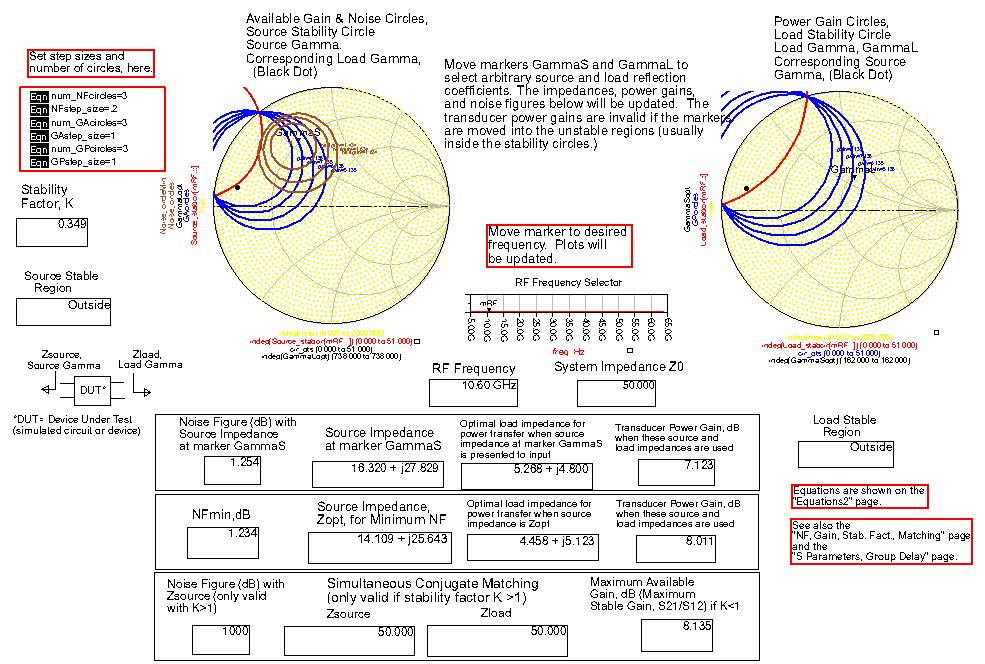
7 One Of The Problems With Long Stubs Page 13 Understanding Device Stability Page 14 7

8 Simulation Results In Preconfigured Data Display Page 15 Simulation Results In Preconfigured Data Display Page 16 8


9 Varying The Bias Voltage And Observing Device Behavior Page 17 Review Device Geometry To Better Understand How And Where Feedback Can Be Implemented Page 18 9


10 Considered Series Feedback In The Source Page 19 Removing One Via Has Considerable Effect On Stability Since the device s Source has proven to be a very sensitive area if we were to base our design on adding stability elements to this area the design would also prove sensitive or not very producible. Page 20 10
11 Neither Inductive Nor Resistive Shunt Feedback Helped Page 21 Let s Consider Drain To Gate Feedback To get a better understanding of how to model this feedback mechanism we need to consider how it will be implemented Page 22 11


12 Feedback Implementation The gate to drain feedback requires routing around one of the vias. The additions to ADS 2009 PDKs allows easy and quick routing. Trace Routing Trace Routing Extraction Into Microstrip Elements Page 23 Feedback Based On Layout Implementation Page 24 12


13 Quick Monte Carlo Check With Process Statistics Enabled Page 25 ADS Has Routines To Build Matching Networks Page 26 13

14 S-Parameter Application Note Page 27 Using Rollett s Stability Analysis And Conjugate Matching Page 28 14
15 With A Little Tuning Design Was Quickly Centered to WPAN Frequency Range Page 29 Three Stage Amplifier Page 30 15
16 Linear 3-Stage Amplifier Performance Page 31 Non-Linear Amplifier Performance Page 32 16


17 Using ADS Built-In Amplifier Test Benches Page 33 Power Sweeps/Gain/Transisent Response Page 34 17


18 Load-Pull Contours Page 35 Overlay Of Power Contours And PAE Page 36 18


19 Using Design Sync And Some Hand Edits To Create Initial Layout Page 37 Desktop DRC TQP13 PDK MMIC Toolbar Mail DRC PDK Toolbars are implemented for each individual process. Page 38 19

20 ADS Desktop DRC Step 1 Invoke the Desktop DRC Tool Step 2 Select Rule File Step 3 Click on Run Page 39 ADS Desktop DRC Results Viewer Page 40 20


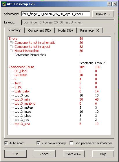
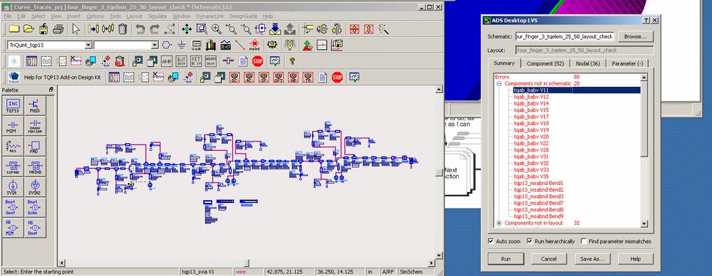
21 ADS Desktop LVS Page 41 Components not in Schematic Page 42 21


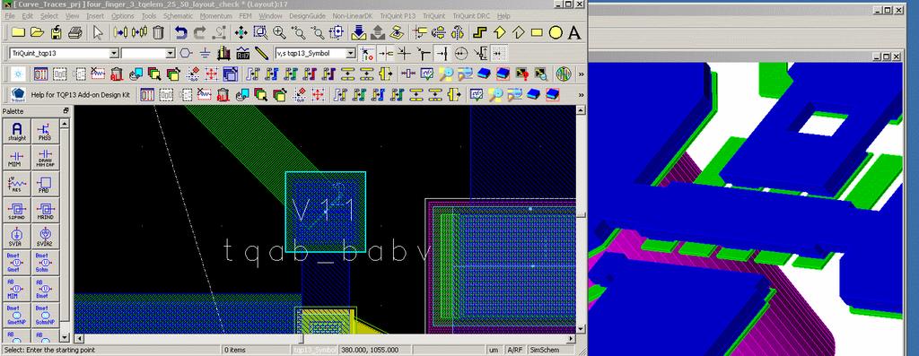
22 Final TriQuint Layout With Clean DRC Run Page 43 3D Rendering Of Design Page 44 22


23 Reticle Cell Layout Page 45 Close-up Of Device Feedback Page 46 23


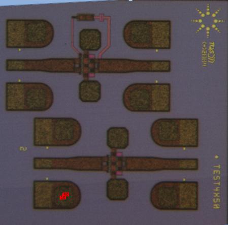
24 Three Stage Amplifier Page 47 Individual Devices Page 48 24


25 Test/Cal Standards Page 49 Final Assembly Ready For Test Page 50 25


26 Cascade Elite 300 Prober Page 51 Positioning Amplifiers Page 52 26

27 Amplifier Under Test Page 53 Measured Vs. Simulated Measurements In theory there is no difference between theory and practice. In practice there is. -Yogi Berra Page 54 27


28 Momentum Simulation For First Stage, Start Of Investigating Differencies Page 55 Schematic Vs. Schematic W/Momentum Results Page 56 28
29 The Additional Couple Within The First Stage Shows A Frequency Shift To The Lower Frequency Range First Stage performance with empirical models First Stage performance with Momentum results Page 57 WPAN Wireless Library Product Features HRP Source Preamble: - Time domain - Frequency domain Header - PHY header - MAC header - CRC, Scrambling - RS coding, Outer interleaver - 1/3 Convolutional coding, bit interleaver, tone interleaver Data - Sub-packet structure - CRC, Scrambling - RS coding, Outer interleaver - Puncturing convolutional coding, bit interleaver, tone interleaver OFDM modulation Measurement Test Benches: Spectrum CCDF Waveform EVM HRP Receiver Frame and frequency synchronization De-framing Cyclic prefix removing Channel estimator Phase tracking Equalizer Demapper Decoder Measurement Test Benches: RawBER and BER on AWGN RX Sensitivity Page 58 29


30 HRP Transmitter Test Benches Page 59 Initial WPAN Simulations Page 60 30
31 Next Steps On the Post Webinar Survey, please tell us if you d like to See a video of full characterization/measurement results Attend a live hands-on-workshop in your area Be invited to future webinars RF/Microwave IC & Package Analysis & Design w/3d Electromagnetic design software Power Amplifier & Mixer design & modeling w/x-parameters Page 61 Q&A If you ask me anything I don't know, I'm not going to answer. - Yogi Berra Page 62 31
32 32
Front-To-Back MMIC Design Flow with ADS. Speed MMICs to market Save money and achieve high yield
 Front-To-Back MMIC Design Flow with ADS Speed MMICs to market Save money and achieve high yield 1 Unique Tools for Robust Designs, First Pass, and High Yield Yield Sensitivity Histogram (YSH) to components
Design and Layout of a X-Band MMIC Power Amplifier in a Phemt Technology
 Design and Layout of a X-Band MMIC Power Amplifier in a Phemt Technology Renbin Dai, and Rana Arslan Ali Khan Abstract The design of Class A and Class AB 2-stage X band Power Amplifier is described in
Innovations in EDA Webcast Series
 Welcome Innovations in EDA Webcast Series August 2, 2012 Jack Sifri MMIC Design Flow Specialist IC, Laminate, Package Multi-Technology PA Module Design Methodology Realizing the Multi-Technology Vision
The wireless industry
 From May 2007 High Frequency Electronics Copyright Summit Technical Media, LLC RF SiP Design Verification Flow with Quadruple LO Down Converter SiP By HeeSoo Lee and Dean Nicholson Agilent Technologies
Application Note 5057
 A 1 MHz to MHz Low Noise Feedback Amplifier using ATF-4143 Application Note 7 Introduction In the last few years the leading technology in the area of low noise amplifier design has been gallium arsenide
Low Noise Amplifier Design Methodology Summary By Ambarish Roy, Skyworks Solutions, Inc.
 February 2014 Low Noise Amplifier Design Methodology Summary By Ambarish Roy, Skyworks Solutions, Inc. Low Noise Amplifiers (LNAs) amplify weak signals received by the antenna in communication systems.
A Survey of Load Pull Simulation Capabilities How do they Help You Design Power Amplifiers?
 A Survey of Load Pull Simulation Capabilities How do they Help You Design Power Amplifiers? Agilent EEsof EDA IMS 2010 MicroApps Andy Howard Agilent Technologies 1 Outline Power amplifier design questions
Agilent EEsof EDA. Enabling First Pass Success. Chee Keong, Teo Business Development Manager EEsof South Asia. Agilent Restricted
 Agilent EEsof EDA Enabling First Pass Success Chee Keong, Teo Business Development Manager EEsof South Asia EEsof EDA is Strategic to Agilent Technologies As the world s premier measurement company, Agilent
From Antenna to Bits:
 From Antenna to Bits: Wireless System Design with MATLAB and Simulink Cynthia Cudicini Application Engineering Manager MathWorks cynthia.cudicini@mathworks.fr 1 Innovations in the World of Wireless Everything
30% PAE W-band InP Power Amplifiers using Sub-quarter-wavelength Baluns for Series-connected Power-combining
 2013 IEEE Compound Semiconductor IC Symposium, October 13-15, Monterey, C 30% PAE W-band InP Power Amplifiers using Sub-quarter-wavelength Baluns for Series-connected Power-combining 1 H.C. Park, 1 S.
LOW COST PHASED ARRAY ANTENNA TRANSCEIVER FOR WPAN APPLICATIONS
 LOW COST PHASED ARRAY ANTENNA TRANSCEIVER FOR WPAN APPLICATIONS Introduction WPAN (Wireless Personal Area Network) transceivers are being designed to operate in the 60 GHz frequency band and will mainly
An E-band Voltage Variable Attenuator Realised on a Low Cost 0.13 m PHEMT Process
 An E-band Voltage Variable Attenuator Realised on a Low Cost 0.13 m PHEMT Process Abstract Liam Devlin and Graham Pearson Plextek Ltd (liam.devlin@plextek.com) E-band spectrum at 71 to 76GHz and 81 to
University of Bristol - Explore Bristol Research. Peer reviewed version. Link to published version (if available): /ICCE.2012.
: /ICCE.2012.") Zhu, X., Doufexi, A., & Koçak, T. (2012). A performance enhancement for 60 GHz wireless indoor applications. In ICCE 2012, Las Vegas Institute of Electrical and Electronics Engineers (IEEE). DOI: 10.1109/ICCE.2012.6161865
Zhu, X., Doufexi, A., & Koçak, T. (2012). A performance enhancement for 60 GHz wireless indoor applications. In ICCE 2012, Las Vegas Institute of Electrical and Electronics Engineers (IEEE). DOI: 10.1109/ICCE.2012.6161865
RF/Microwave Circuits I. Introduction Fall 2003
 Introduction Fall 03 Outline Trends for Microwave Designers The Role of Passive Circuits in RF/Microwave Design Examples of Some Passive Circuits Software Laboratory Assignments Grading Trends for Microwave
Stuart Glynn Power Amplifier Design Engineer
 Stuart Glynn Power Amplifier Design Engineer Keysight Technologies 2017 How to Design an X-band MMIC PA Stuart Glynn and Liam Devlin Introduction Target specification and application Design approach Device
Basic idea: divide spectrum into several 528 MHz bands.
 IEEE 802.15.3a Wireless Information Transmission System Lab. Institute of Communications Engineering g National Sun Yat-sen University Overview of Multi-band OFDM Basic idea: divide spectrum into several
Bridging the Gap between System & Circuit Designers
 Bridging the Gap between System & Circuit Designers October 27, 2004 Presented by: Kal Kalbasi Q & A Marc Petersen Copyright 2003 Agilent Technologies, Inc. The Gap System Communication System Design System
Efficiently simulating a direct-conversion I-Q modulator
 Efficiently simulating a direct-conversion I-Q modulator Andy Howard Applications Engineer Agilent Eesof EDA Overview An I-Q or vector modulator is a commonly used integrated circuit in communication systems.
Thales UK Designs GaN MMIC/Packaging for EU MAGNUS Program Using NI AWR Software
 Success Story Thales UK Designs GaN MMIC/Packaging for EU MAGNUS Program Using NI AWR Software Company Profile Thales UK is a world-leading innovator across the aerospace, defense, ground transportation,
Fifth-generation (5G)
") Raising the Levels of 5G Millimeter-Wave Signals Fifth-generation (5G) wireless network technology is being touted as the true next generation of wireless communications, capable of performance levels
Raising the Levels of 5G Millimeter-Wave Signals Fifth-generation (5G) wireless network technology is being touted as the true next generation of wireless communications, capable of performance levels
High Efficiency Class-F MMIC Power Amplifiers at Ku-Band
 High Efficiency Class-F MMIC Power Amplifiers at Ku-Band Matthew T. Ozalas The MITRE Corporation 2 Burlington Road, Bedford, MA 173 mozalas@mitre.org Abstract Two high efficiency Ku-band phemt power amplifier
The Design of E-band MMIC Amplifiers
 The Design of E-band MMIC Amplifiers Liam Devlin, Stuart Glynn, Graham Pearson, Andy Dearn * Plextek Ltd, London Road, Great Chesterford, Essex, CB10 1NY, UK; (lmd@plextek.co.uk) Abstract The worldwide
AWR. SIP Flow White Paper UNDERSTANDING AVAILABLE TOOLS FOR RF SYSTEM-IN-PACKAGE AND MULTI-CHIP-MODULE DESIGN AND OPTIMIZATION
 UNDERSTANDING AVAILABLE TOOLS FOR RF SYSTEM-IN-PACKAGE AND MULTI-CHIP-MODULE DESIGN AND OPTIMIZATION RF system-in-package (SiP) and multi-chip-module (MCM) designs present engineers with the challenge
57-65GHz CMOS Power Amplifier Using Transformer-Coupling and Artificial Dielectric for Compact Design
 57-65GHz CMOS Power Amplifier Using Transformer-Coupling and Artificial Dielectric for Compact Design Tim LaRocca, and Frank Chang PA Symposium 1/20/09 Overview Introduction Design Overview Differential
15 GHz Voltage Controlled Osc Odeneho Anaman 10 GHz Voltage Controlled Osc Enoch Wong
 Fall 2014 JHU EE787 MMIC Design Student Projects Supported by TriQuint, Applied Wave Research, and Agilent Professors John Penn and Dr. Willie Thompson 15 GHz Voltage Controlled Osc Odeneho Anaman 10 GHz
Using Sonnet EM Analysis with Cadence Virtuoso in RFIC Design. Sonnet Application Note: SAN-201B July 2011
 Using Sonnet EM Analysis with Cadence Virtuoso in RFIC Design Sonnet Application Note: SAN-201B July 2011 Description of Sonnet Suites Professional Sonnet Suites Professional is an industry leading full-wave
Low Noise Amplifier for 3.5 GHz using the Avago ATF Low Noise PHEMT. Application Note 1271
 Low Noise Amplifier for 3. GHz using the Avago ATF-3143 Low Noise PHEMT Application Note 171 Introduction This application note describes a low noise amplifier for use in the 3.4 GHz to 3.8 GHz wireless
Microwave and RF Engineering
 Microwave and RF Engineering Volume 1 An Electronic Design Automation Approach Ali A. Behagi and Stephen D. Turner BT Microwave LLC State College, PA 16803 Copyrighted Material Microwave and RF Engineering
1 of 7 12/20/ :04 PM
 1 of 7 12/20/2007 11:04 PM Trusted Resource for the Working RF Engineer [ C o m p o n e n t s ] Build An E-pHEMT Low-Noise Amplifier Although often associated with power amplifiers, E-pHEMT devices are
mmw to THz ultra high data rate radio access technologies
 mmw to THz ultra high data rate radio access technologies Dr. Laurent HERAULT VP Europe, CEA LETI Pierre Vincent Head of RF IC design Lab, CEA LETI Outline mmw communication use cases and standards mmw
Modeling Physical PCB Effects 5&
 Abstract Getting logical designs to meet specifications is the first step in creating a manufacturable design. Getting the physical design to work is the next step. The physical effects of PCB materials,
Outline / Wireless Networks and Applications Lecture 2: Networking Overview and Wireless Challenges. Protocol and Service Levels
 18-452/18-750 Wireless s and s Lecture 2: ing Overview and Wireless Challenges Peter Steenkiste Carnegie Mellon University Spring Semester 2017 http://www.cs.cmu.edu/~prs/wirelesss17/ Peter A. Steenkiste,
ATF-531P8 900 MHz High Linearity Amplifier. Application Note 1372
 ATF-531P8 9 MHz High Linearity Amplifier Application Note 1372 Introduction This application note describes the design and construction of a single stage 85 MHz to 9 MHz High Linearity Amplifier using
Methodology for MMIC Layout Design
 17 Methodology for MMIC Layout Design Fatima Salete Correra 1 and Eduardo Amato Tolezani 2, 1 Laboratório de Microeletrônica da USP, Av. Prof. Luciano Gualberto, tr. 3, n.158, CEP 05508-970, São Paulo,
Millimeter-Wave Amplifiers for E- and V-band Wireless Backhaul Erik Öjefors Sivers IMA AB
 Millimeter-Wave Amplifiers for E- and V-band Wireless Backhaul Erik Öjefors Sivers IMA AB THz-Workshop: Millimeter- and Sub-Millimeter-Wave circuit design and characterization 26 September 2014, Venice
Final Circuit & System Simulation - with Optional
 Final Circuit & System Simulation - with Optional Co-Simulation Slide 9-1 What is the final topic in this class? Simulation of your amp_1900 and filters in the receiver system to verify analog performance.
Direct-Conversion I-Q Modulator Simulation by Andy Howard, Applications Engineer Agilent EEsof EDA
 Direct-Conversion I-Q Modulator Simulation by Andy Howard, Applications Engineer Agilent EEsof EDA Introduction This article covers an Agilent EEsof ADS example that shows the simulation of a directconversion,
A 1-W GaAs Class-E Power Amplifier with an FBAR Filter Embedded in the Output Network
 A 1-W GaAs Class-E Power Amplifier with an FBAR Filter Embedded in the Output Network Kyle Holzer and Jeffrey S. Walling University of Utah PERFIC Lab, Salt Lake City, UT 84112, USA Abstract Integration
Fall 2009 JHU EE787 MMIC Design Student Projects Supported by TriQuint, and Agilent Eesof Professors John Penn and Dr.
 Driver Amplifier Robert Schaefer Power Amplifier 1 Rowland Foster Low Noise Amplifier 2 Clay Couey Up/Down Mixer Steve Moeglein Volt. Cont. Osc. 1 Clay Couey Fall 2009 JHU EE787 MMIC Design Student Projects
Application Note 1299
 A Low Noise High Intercept Point Amplifier for 9 MHz Applications using ATF-54143 PHEMT Application Note 1299 1. Introduction The Avago Technologies ATF-54143 is a low noise enhancement mode PHEMT designed
Complete RF And Microwave Design Flow with AWR Design Environment. Tabish Khan, AWR Corporation
 Complete RF And Microwave Design Flow with AWR Design Environment Tabish Khan, AWR Corporation Traditional Serial Design Flow Separate tools, user interfaces, netlists and databases System Design Design
2 GHz to 30 GHz, GaAs, phemt, MMIC, Low Noise Amplifier HMC8402
 2 GHz to 3 GHz, GaAs, phemt, MMIC, Low Noise Amplifier HMC842 FEATURES Output power for 1 db compression (P1dB): 21. dbm typical Saturated output power (PSAT): 22 dbm typical Gain: 13. db typical Noise
ISSCC 2006 / SESSION 11 / RF BUILDING BLOCKS AND PLLS / 11.9
 ISSCC 2006 / SESSION 11 / RF BUILDING BLOCKS AND PLLS / 11.9 11.9 A Single-Chip Linear CMOS Power Amplifier for 2.4 GHz WLAN Jongchan Kang 1, Ali Hajimiri 2, Bumman Kim 1 1 Pohang University of Science
Dual-band LNA Design for Wireless LAN Applications. 2.4 GHz LNA 5 GHz LNA Min Typ Max Min Typ Max
 Dual-band LNA Design for Wireless LAN Applications White Paper By: Zulfa Hasan-Abrar, Yut H. Chow Introduction Highly integrated, cost-effective RF circuitry is becoming more and more essential to the
Integrated Solutions for Testing Wireless Communication Systems
 TOPICS IN RADIO COMMUNICATIONS Integrated Solutions for Testing Wireless Communication Systems Dingqing Lu and Zhengrong Zhou, Agilent Technologies Inc. ABSTRACT Wireless communications standards have
ATF-531P8 E-pHEMT GaAs FET Low Noise Amplifier Design for 800 and 900 MHz Applications. Application Note 1371
 ATF-31P8 E-pHEMT GaAs FET Low Noise Amplifier Design for 8 and 9 MHz Applications Application Note 1371 Introduction A critical first step in any LNA design is the selection of the active device. Low cost
Flip-Chip for MM-Wave and Broadband Packaging
 1 Flip-Chip for MM-Wave and Broadband Packaging Wolfgang Heinrich Ferdinand-Braun-Institut für Höchstfrequenztechnik (FBH) Berlin / Germany with contributions by F. J. Schmückle Motivation Growing markets
HMC5805ALS6 AMPLIFIERS - LINEAR & POWER - SMT. Typical Applications. Features. Functional Diagram
 HMC585ALS6 v2.517 GaAs phemt MMIC.25 WATT POWER AMPLIFIER DC - 4 GHz Typical Applications The HMC585ALS6 is ideal for: Test Instrumentation Microwave Radio & VSAT Military & Space Telecom Infrastructure
Project: IEEE P Working Group for Wireless Personal Area Networks N
 Project: IEEE P802.15 Working Group for Wireless Personal Area Networks N (WPANs( WPANs) Title: [60GHz-band Gigabit Transceivers and Their Applications ] Date Submitted: [12 January 2004] Source: [Kenichi
Performance Analysis of WiMAX Physical Layer Model using Various Techniques
 Volume-4, Issue-4, August-2014, ISSN No.: 2250-0758 International Journal of Engineering and Management Research Available at: www.ijemr.net Page Number: 316-320 Performance Analysis of WiMAX Physical
Load-Pull Analysis Using NI AWR Software
 Application Example Load-Pull Analysis Using NI AWR Software Overview Load-pull analysis is one of the key design techniques in amplifier design and is often used for determining an appropriate load. Amplifiers
Project: IEEE P Working Group for Wireless Personal Area Networks N
 Project: IEEE P802.15 Working Group for Wireless Personal Area Networks N (WPANs) Title: [The Scalability of UWB PHY Proposals] Date Submitted: [July 13, 2004] Source: [Matthew Welborn] Company [Freescale
DESIGN OF POWER-SCALABLE GALLIUM NITRIDE CLASS E POWER AMPLIFIERS
 DESIGN OF POWER-SCALABLE GALLIUM NITRIDE CLASS E POWER AMPLIFIERS Thesis Submitted to The School of Engineering of the UNIVERSITY OF DAYTON In Partial Fulfillment of the Requirements for The Degree of
6-18 GHz MMIC Drive and Power Amplifiers
 JOURNAL OF SEMICONDUCTOR TECHNOLOGY AND SCIENCE, VOL.2, NO. 2, JUNE, 02 125 6-18 GHz MMIC Drive and Power Amplifiers Hong-Teuk Kim, Moon-Suk Jeon, Ki-Woong Chung, and Youngwoo Kwon Abstract This paper
Packaged mm-wave GaN, GaAs and Si ICs for 5G and automotive radar
 Packaged mm-wave GaN, GaAs and Si ICs for 5G and automotive radar Eric Leclerc UMS 1 st Nov 2018 Outline Why heterogenous integration? About UMS Technology portfolio Design tooling: Cadence / GoldenGate
Project: IEEE P Working Group for Wireless Personal Area Networks N
 Slide 1 Project: IEEE P802.15 Working Group for Wireless Personal Area Networks N (WPANs( WPANs) Title: [A Modified Performance Evaluation Scheme for Computer Simulation ] Date Submitted: [November 15,
RF Board Design for Next Generation Wireless Systems
 RF Board Design for Next Generation Wireless Systems Page 1 Introduction Purpose: Provide basic background on emerging WiMax standard Introduce a new tool for Genesys that will aide in the design and verification
ECEN 474/704 Lab 8: Two-Stage Miller Operational Amplifier
 ECEN 474/704 Lab 8: Two-Stage Miller Operational Amplifier Objective Design, simulate and test a two-stage operational amplifier Introduction Operational amplifiers (opamp) are essential components of
SmartSpice RF Harmonic Balance Based RF Simulator. Advanced RF Circuit Simulation
 SmartSpice RF Harmonic Balance Based RF Simulator Advanced RF Circuit Simulation SmartSpice RF Overview Uses harmonic balance approach to solve system equations in frequency domain Well suited for RF and
Thank you for downloading one of our ANSYS whitepapers we hope you enjoy it.
 Thank you! Thank you for downloading one of our ANSYS whitepapers we hope you enjoy it. Have questions? Need more information? Please don t hesitate to contact us! We have plenty more where this came from.
Local Oscillator Phase Noise Influence on Single Carrier and OFDM Modulations
 Local Oscillator Phase Noise Influence on Single Carrier and OFDM Modulations Vitor Fialho,2, Fernando Fortes 2,3, and Manuela Vieira,2 Universidade Nova de Lisboa Faculdade de Ciências e Tecnologia DEE
81 GHz to 86 GHz, E-Band Power Amplifier With Power Detector HMC8142
 Data Sheet 8 GHz to 86 GHz, E-Band Power Amplifier With Power Detector FEATURES GENERAL DESCRIPTION Gain: db typical The is an integrated E-band gallium arsenide (GaAs), Output power for db compression
ECE145a/218a: Exercise in Running the Simulation Tools and Introductory Circuits
 ECE145a/218a: Exercise in Running the Simulation Tools and Introductory Circuits The exercises below are designed to **complement* your running the ADS tutorials (in ADS documentation), which are highly
An FPGA Case Study: Narrowband COFDM Video Transceiver for Drones, UAV, and UGV. Produced by EE Times
 An FPGA Case Study: Narrowband COFDM Video Transceiver for Drones, UAV, and UGV #eelive Produced by EE Times An FPGA Case Study System Definition Implementation Verification and Validation CNR1 Narrowband
Welcome. Steven Baker Founder & Director OpenET Alliance. Andy Howard Senior Application Specialist Agilent EEsof EDA Agilent Technologies, Inc.
 Welcome Steven Baker Founder & Director OpenET Alliance Andy Howard Senior Application Specialist Agilent EEsof EDA 1 Outline Steven Baker, OpenET Alliance What problem are we trying to solve? What is
10 GHz LNA for Amateur Radio by K5TRA
 Introduction Ham radio operation on 10 GHz is somewhat exotic. This is far removed from global short-wave communication below 30 MHz, or regional VHF and UHF communication. Despite the arcane nature of
When Should You Apply 3D Planar EM Simulation?
 When Should You Apply 3D Planar EM Simulation? Agilent EEsof EDA IMS 2010 MicroApps Andy Howard Agilent Technologies 1 3D planar EM is now much more of a design tool Solves bigger problems and runs faster
DESIGN OF HIGH POWER AND EFFICIENT RF LDMOS PA FOR ISM APPLICATIONS
 DESIGN OF HIGH POWER AND EFFICIENT RF LDMOS PA FOR ISM APPLICATIONS Farhat Abbas and John Gajadharsing NXP Semiconductors Nijmegen, The Netherlands Farhat.abbas@nxp.com Very high performance in power and
California Eastern Laboratories
 California Eastern Laboratories AN143 Design of Power Amplifier Using the UPG2118K APPLICATION NOTE I. Introduction Renesas' UPG2118K is a 3-stage 1.5W GaAs MMIC power amplifier that is usable from approximately
Design of a Low Noise Amplifier using 0.18µm CMOS technology
 The International Journal Of Engineering And Science (IJES) Volume 4 Issue 6 Pages PP.11-16 June - 2015 ISSN (e): 2319 1813 ISSN (p): 2319 1805 Design of a Low Noise Amplifier using 0.18µm CMOS technology
ENHANCING BER PERFORMANCE FOR OFDM
 RESEARCH ARTICLE OPEN ACCESS ENHANCING BER PERFORMANCE FOR OFDM Amol G. Bakane, Prof. Shraddha Mohod Electronics Engineering (Communication), TGPCET Nagpur Electronics & Telecommunication Engineering,TGPCET
20 GHz to 44 GHz, GaAs, phemt, MMIC, Low Noise Amplifier HMC1040CHIPS
 Data Sheet FEATURES Low noise figure: 2 db typical High gain: 25. db typical P1dB output power: 13.5 dbm, 2 GHz to GHz High output IP3: 25.5 dbm typical Die size: 1.39 mm 1..2 mm APPLICATIONS Software
A GHz MONOLITHIC GILBERT CELL MIXER. Andrew Dearn and Liam Devlin* Introduction
 A 40 45 GHz MONOLITHIC GILBERT CELL MIXER Andrew Dearn and Liam Devlin* Introduction Millimetre-wave mixers are commonly realised using hybrid fabrication techniques, with diodes as the nonlinear mixing
Microwave Office Application Note
 Microwave Office Application Note INTRODUCTION Wireless system components, including gallium arsenide (GaAs) pseudomorphic high-electron-mobility transistor (phemt) frequency doublers, quadruplers, and
60 GHz Transceiver IC Design Using High-Mobility.15-micron GaAs Process
 white paper 60 GHz Transceiver IC Design Using High-Mobility.15-micron GaAs Process TABLE OF CONtENtS Executive Summary... 3 Introduction... 4 Millimeter-Wave MMIC Design... 5 Design Environment... 6 Millimeter-Wave
Microwave Office Application Note
 Microwave Office Application Note INTRODUCTION Wireless system components, including gallium arsenide (GaAs) pseudomorphic high-electron-mobility transistor (phemt) frequency doublers, quadruplers, and
Including the proper parasitics in a nonlinear
 Effects of Parasitics in Circuit Simulations Simulation accuracy can be improved by including parasitic inductances and capacitances By Robin Croston California Eastern Laboratories Including the proper
Simple Class A Power Amplifier Circuits Design Tutorial On Doherty
 Simple Class A Power Amplifier Circuits Design Tutorial On Doherty Conference, Tutorials, Advanced-Circuit-Design Forums, and the Short Course. Memories have evolved continuously since the simple days
Chapter 3 Introduction to OFDM-Based Systems
 Chapter 3 Introduction to OFDM-Based Systems 3.1 Eureka 147 DAB System he Eureka 147 DAB [5] system has the following features: it has sound quality comparable to that of CD, it can provide maximal coverage
DC to 28 GHz, GaAs phemt MMIC Low Noise Amplifier HMC8401
 FEATURES Output power for db compression (PdB):.5 dbm typical Saturated output power (PSAT): 9 dbm typical Gain:.5 db typical Noise figure:.5 db Output third-order intercept (IP3): 26 dbm typical Supply
What is New in Wireless System Design
 What is New in Wireless System Design Houman Zarrinkoub, PhD. houmanz@mathworks.com 2015 The MathWorks, Inc. 1 Agenda Landscape of Wireless Design Our Wireless Initiatives Antenna-to-Bit simulation Smart
802.11a Hardware Implementation of an a Transmitter
 802a Hardware Implementation of an 802a Transmitter IEEE Standard for wireless communication Frequency of Operation: 5Ghz band Modulation: Orthogonal Frequency Division Multiplexing Elizabeth Basha, Steve
Performance Evaluation of BPSK modulation Based Spectrum Sensing over Wireless Fading Channels in Cognitive Radio
 IOSR Journal of Electronics and Communication Engineering (IOSR-JECE) e-issn: 2278-2834,p- ISSN: 2278-8735.Volume 9, Issue 6, Ver. IV (Nov - Dec. 2014), PP 24-28 Performance Evaluation of BPSK modulation
Agilent Technologies Solutions for MB-OFDM Ultra-wideband
 Agilent Technologies Solutions for MB-OFDM Ultra-wideband Application Note Bringing proven experience in emerging technologies to UWB Introduction Agilent Technologies provides the most complete range
Design of Class F Power Amplifiers Using Cree GaN HEMTs and Microwave Office Software to Optimize Gain, Efficiency, and Stability
 White Paper Design of Class F Power Amplifiers Using Cree GaN HEMTs and Microwave Office Software to Optimize Gain, Efficiency, and Stability Overview This white paper explores the design of power amplifiers
77 GHz VCO for Car Radar Systems T625_VCO2_W Preliminary Data Sheet
 77 GHz VCO for Car Radar Systems Preliminary Data Sheet Operating Frequency: 76-77 GHz Tuning Range > 1 GHz Output matched to 50 Ω Application in Car Radar Systems ESD: Electrostatic discharge sensitive
30 ma flash LDO voltage regulator (output voltage 1.8 ± 0.2 V)
") SPECIFICATION 1 FEATURES Global Foundries CMOS 55 nm Low drop out Low current consumption Two modes operations: Normal, Economy Mode operation Bypass No discrete filtering capacitors required (cap-less
SPECIFICATION 1 FEATURES Global Foundries CMOS 55 nm Low drop out Low current consumption Two modes operations: Normal, Economy Mode operation Bypass No discrete filtering capacitors required (cap-less
Project: IEEE P Working Group for Wireless Personal Area Networks N
 Project: IEEE P802.15 Working Group for Wireless Personal Area Networks N (WPANs( WPANs) Title: [MSK-based 60GHz PHY Proposal] Date Submitted: [7 May, 2007] Source: [Troy Beukema, Brian Floyd, Brian Gaucher,
Ultra Wideband Amplifier Senior Project Proposal
 Ultra Wideband Amplifier Senior Project Proposal Saif Anwar Sarah Kief Senior Project Fall 2007 December 4, 2007 Advisor: Dr. Prasad Shastry Department of Electrical & Computer Engineering Bradley University
A Simulation Methodology for Wirebonds Interconnects of Radiofrequency Integrated Circuits
 A Simulation Methodology for Wirebonds Interconnects of Radiofrequency Integrated Circuits Hercílio M. Cavalcanti 1 and Leandro T. Manera 2 1 Hercílio M. Cavalcanti, CTI Renato Archer, Campinas, São Paulo,
RF/Microwave Amplifier Design Using Harmonic Balance Simulation With Only S-parameter Data
 Application Note RF/Microwave Amplifier Design Using Harmonic Balance Simulation With Only S-parameter Data Overview It is widely held that S-parameters combined with harmonic balance (HB) alone cannot
Signal Studio for IoT
 Signal Studio for IoT N7610C TECHNICAL OVERVIEW Create Keysight validated and performance-optimized reference signals compliant to IEEE 802.15.4 (for ZigBee), 802.15.4g (for Wi-SUN), LoRa CSS and ITU-T
UNIVERSITY OF MICHIGAN DEPARTMENT OF ELECTRICAL ENGINEERING : SYSTEMS EECS 555 DIGITAL COMMUNICATION THEORY
 UNIVERSITY OF MICHIGAN DEPARTMENT OF ELECTRICAL ENGINEERING : SYSTEMS EECS 555 DIGITAL COMMUNICATION THEORY Study Of IEEE P802.15.3a physical layer proposals for UWB: DS-UWB proposal and Multiband OFDM
SmartSpice RF Harmonic Balance Based and Shooting Method Based RF Simulation
 SmartSpice RF Harmonic Balance Based and Shooting Method Based RF Simulation Silvaco Overview SSRF Attributes Harmonic balance approach to solve system of equations in frequency domain Well suited for
A High Efficiency and Wideband Doherty Power Amplifier for 5G. Master s thesis in Wireless, Photonics and Space Engineering HALIL VOLKAN HUNERLI
 A High Efficiency and Wideband Doherty Power Amplifier for 5G Master s thesis in Wireless, Photonics and Space Engineering HALIL VOLKAN HUNERLI Department of Microtechnology and Nanoscience-MC2 CHALMERS
GaAs, phemt, MMIC, Power Amplifier, 2 GHz to 50 GHz HMC1126
 GaAs, phemt, MMIC, Power Amplifier, 2 GHz to GHz FEATURES FUNCTIONAL BLOCK DIAGRAM Output power for 1 db compression (P1dB): 1. db typical Saturated output power (PSAT): dbm typical Gain: 11 db typical
Fundamentals of RF Design RF Back to Basics 2015
 Fundamentals of RF Design 2015 Updated January 1, 2015 Keysight EEsof EDA Objectives Review Simulation Types Understand fundamentals on S-Parameter Simulation Additional Linear and Non-Linear Simulators
71 GHz to 76 GHz, 1 W E-Band Power Amplifier with Power Detector ADMV7710
 Data Sheet FEATURES Gain: db typical Output power for db compression: dbm typical Saturated output power: 29 dbm typical Output third-order intercept: dbm typical Input return loss: 8 db typical Output
DSP IMPLEMENTATION OF HIGH SPEED WLAN USING OFDM
 DSP IMPLEMENTATION OF HIGH SPEED WLAN USING OFDM M. Fahim Tariq, Tony Horseman, Andrew Nix Centre for Communications Research, University of Bristol, Merchant Venturers Building, Woodland Road, Bristol
FOUNDRY SERVICE. SEI's FEATURE. Wireless Devices FOUNDRY SERVICE. SRD-800DD, SRD-500DD D-FET Process Lg=0.8, 0.5µm. Ion Implanted MESFETs SRD-301ED
 FOUNDRY SERVICE 01.04. Foundry services have been one of the core businesses at SEI, providing sophisticated GaAs IC technology for all customers. SEI offers very flexible service to support the customers