10-Channel Digital Proportional R/C System INSTRUCTION MANUAL
|
|
|
- Darcy McKinney
- 6 years ago
- Views:
Transcription


1 INSTRUCTION MANUAL
2 Technical updates and additional programming examples available at:
3 Introduction
4
5
6 INTRODUCTION Thank you for purchasing a Futaba T-FHSS Air-2.4GHz 10J series digital proportional R/C system. This system is extremely versatile and may be used by beginners and pros alike. In order Futaba Service Center. subject to change without notice. Support and Service: It is recommended to have your Futaba equipment serviced annually during your hobby s off season to ensure safe operation. IN NORTH AMERICA programming. Please be sure to regularly visit the 10J Frequently Asked Questions web site information on the 10J radio system and is updated regularly. Any technical updates and US for the most rapid and convenient response. to assist you. FOR SERVICE ONLY: Futaba Service Center futabaservice@hobbico.com FOR SUPPORT : (PROGRAMMING AND USER QUESTIONS) Please start here for answers to most questions: OUTSIDE NORTH AMERICA problems or service needs. the systems sold in North America only. Products purchased elsewhere may vary. Always contact your region s support center for assistance.
7 for use in any application other than the control of models for hobby and recreational purposes. restricted under Japanese law to such purposes. 2. Exportation precautions: the laws governing the country of destination which govern devices that emit radio frequencies. If Prior approval of the appropriate government authorities may be required. If you have purchased been met. (b) Use of this product with other than models may be restricted by Export and Trade Control be utilized to operate equipment other than radio controlled models. the warranty. Compliance Information Statement (for U.S.A.) undesired operation. (3) This module meets the requirements for a mobile device that may be used at separation distances of more than 20cm from human body. To meet the RF exposure requirements of the FCC this device shall not be co-located with another transmitting device. The responsible party of this device compliance is: Futaba Service Center indicates that Futaba Corporation is voluntarily participating in an industry-wide convenient alternative to placing used nickel-cadmium batteries into the trash or. (for USA) You may contact your local recycling center for information on where to return the spent battery. Please involvement in this program is part of its commitment to protecting our environment and conserving natural resources.
8 Federal Communications Commission Interference Statement (for U.S.A.) against harmful interference in a residential installation. correct the interference by one or more of the following measures: --Reorient or relocate the receiving antenna. --Increase the separation between the equipment and receiver. --Consult the dealer or your Futaba Serivce center for help. CAUTION: To assure continued FCC compliance: user's authority to operate the equipment. Exposure to Radio Frequency Radiation 20cm must be maintained between the antenna of this device and all persons. This device must not be co-located or operating in conjunction with any other antenna or transmitter. Meaning of Special Markings Pay special attention to safety where indicated by the following marks: DANGER - Procedures which may lead to dangerous conditions and cause death/serious injury if not carried out properly. WARNING - Procedures which may lead to a dangerous condition or cause death or CAUTION Warning: Always keep electrical components away from small children. FLYING SAFETY WARNING Have regular maintenance performed. Although your 10J protects the model memories recommend sending your system to the Futaba Service Center annually during your non-
9 NiMH/NiCd Battery Charge the batteries! Stop flying long before your batteries become low on charge. Do not rely on your radio s low battery warning systems, intended only as a precaution, to tell you when to Where to Fly free phone number below. Academy of Model Aeronautics or via the Internet at modelaircraft.org as well as the presence and radio interference in their vicinity.
10 NiMH/NiCd Battery Safety and Handling instructions IMPORTANT! Use only the Futaba special charger included with this set or other chargers approved by the batteries and its surroundings and possibly result in a FIRE! IMPORTANT PRECAUTIONS equals the rated capacity of the battery). excessively hot disconnect the battery from the charger immediately!! Always inspect a battery damaged in any way. battery.
11 proper sequence: 2. Turn on the transmitter power and allow your transmitter to reach its home screen. 4. Turn on your receiver power. cause of the problem. Test to ensure that the FailSafe settings are correct after adjusting them. Turn the transmitter 7. Complete a full range check. disarm your motor/engine. 9. Turn off receiver power. 10. Turn off transmitter power. engine may unexpectedly turn on and cause a severe injury. that the wind won't tip it over. If it is knocked over, the throttle stick may be accidentally In order to maintain complete control of your aircraft it is important that it remains visible at all times Doing so may result in the reduction of the quality of the radio frequency link to the model. Doing so may degrade the quality of the radio frequency transmission. situation.
12 BEFORE USE The Futaba 2.4GHz T-FHSS Air system is employed. A T-FHSS Air bidirectional communication system is used. The voltage of the battery mounted in the data can be displayed at the transmitter by installing various optional telemetry sensors in the fuselage. Telemetry data can be listened to by plugging commercial earphones into the transmitter. Diversity antenna built into the transmitter provides a simple appearance and improves handling ease. S.BUS/S.BUS2 servo channel and various functions can be set by connecting the servo to the transmitter. The transmitter body contains a 30 model memory. swash plate types can also be selected for helicopters. Multi-copter selection is also possible. arbitrarily changed. The trim position is displayed on the LCD. The lever head length can be adjusted. A new lever head shape that reduces slip during operation has been adopted. Mixing and other switches and knobs can be selected. Since the function of the AUX channels (5ch programmable mixing function. Model data can be wirelessly transferred between 10J or 8J transmitters. S.BUS output and conventional channel output are provided. S.BUS and conventional system sharing is possible.
13 T10J transmitter for airplanes or helicopters R3008SB Receiver Switch harness Neck strap *The set contents depend on the type of set. Transmitting frequency: 2.4GHz band Power supply: 6.0V Dry battery The is a. The transmitter can also be switched to *The Futaba system cannot be used with Futaba systems. Use it with a system transmitter and receiver. The is a be used with an receiver by switching to cannot be used. *The and surface system are different. The cannot be used with the or surface system receivers.
14 LiFe. the instructor on a separate transmitter. Note that the T10J transmitter may be connected to another T10J Servos - there are various kinds of servos. Please choose the Futaba servos best suited for the model and system and to acquire the information from a model high up in the sky. Temperature sensor : SBS-01T] [Altitude sensor : SBS-01A] [RPM sensormagnet type : SBS-01RM] [RPM sensoroptical type : SBS-01RO] [GPS sensor : SBS-01G] [Voltage sensor : SBS-01V] Neckstrap - a neckstrap can be connected to your T10J system to make it easier to handle and improve Gyros - a variety of genuine Futaba gyros is available for your aircraft or helicopter needs. Governor - for helicopter use. Automatically adjusts throttle servo position to maintain a constant head Receivers - various models of Futaba receivers may be purchased for use in other models. (Receivers for
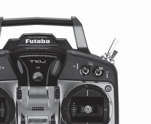
15 Built-in Antenna VR Flap Trim Control This controls CH6, and if flaperon mixing is activated controls the flap. Carrying Handle Digital Trim 5 /CH7 Control SW(B) Rudder Dual Rate Switch SW(A) Elevator Dual Rate Switch SW(F) Snap Roll or Trainer Switch SW(E) Landing Gear Switch /CH5 Digital Trim 6 /CH8 Control SW(C) Elevator - Flap Mixing or Airbrake Mixing Switch SW(D) Aileron Dual Rate Switch SW(H) SW(G) Rudder /Throttle Stick Power LED Throttle Trim Lever Rudder Trim Lever END Key Elevator /Aileron Stick Elevator Trim Lever Aileron Trim Lever Key Key Jog Key Power Switch (Up position: ON) Hook (for optional neckstrap) LCD Panel supplied by the factory. You can change many of the switch positions or functions by selecting a new position within the setting menu for the function you wish to move.
16 Built-in Antenna VR CH8 Knob Carrying Handle Digital Trim 5 SW(B) Rudder Dual Rate Switch SW(A) Elevator Dual Rate Switch SW(F) Idle-up 3 Switch /Gyro/CH5 SW(E) Idle-up 1&2 Switch SW(C) Governor Switch/CH7 SW(D) Aileron Dual Rate Switch SW(H) Trainer Switch SW(G) Throttle - Hold Switch Digital Trim 6 Throttle/Collective Pitch & Rudder Stick Power LED Throttle/Collective Pitch Trim Lever Rudder Trim Lever END Key Elevator /Aileron Stick Elevator Trim Lever Aileron Trim Lever Key Key Jog Key Power Switch (Up position: ON) LCD Panel Hook (for optional neckstrap) by the factory. You can change many of the switch positions or functions by selecting a new position within the setting menu for the function you wish to move.
17 The T10J transmitter is designed to work with available separately. The transmitter batteries used are a matter of personal preference. AA Alkaline batteries are available at any local will need to be purchased from a hobby shop. push and slide down Remove the battery BOX if you choose to use the optional HT5F1800B/FT2F2100B transmitter. And "BATT TYPE" in a PARAMETER is changed into "HT5F1800B : 5.0V FT2F2100B : 5.8V ". Battery cover will be shown the next time when you turn on the power of the transmitter. Do not use the transmitter as it is. Send it to the Futaba Service Center. B
18 The factory default functions activated by the switches and VR for an 10JA Mode 2 for USA transmitter are shown below. Most 10J functions may be reassigned to non-default positions quickly and easily. Basic control assignments of channels 5-10 are quickly adjustable in AUX-CH. Note that most functions need to be activated in the programming to operate. switch commands. Always check that you have the desired switch assignment for each function during set up. SWITCHES are spring-loaded and 2-position; on the 10JA First make sure the throttle stick is in the low throttle position. Push up to turn on. you'll have an alarm until the stick is in the low position.
19 ACRO) 1 Ailerons/Aileron-1 1 /combined Flap-2 & Aileron-1 2 /combined Aileron-1 & Elevator Elevator/combined Aileron-2 & Elevator Throttle 4 Rudder 5 Landing gear/aileron-2 /combined Flap-1 and Aileron Aileron Elevator-2 4 /Mixture control 9 AUX 10 AUX 1 Aileron Differential mode (AILE-DIFF 2 Flaperon mode. 3 to channels 5 and 6. ( AILE-2 4 AILEVATOR 5 ELEVON mode. MULTI COPT) AUX 7 AUX 8 AUX 9 AUX 10 AUX *Use the controller of multicopter corresponding to Futaba.
20 HELI) Throttle 4 Rudder 5 Gyro 6 7 AUX/Governor 8 AUX/ELE2/Mixture control 9 AUX 10 AUX
21 CH 1 Aileron 2 Aileron 2 Aileron 1 Flap 2 Aileron 2 Flap 2 Aileron 4 Flap 1 Aileron Aileron Aileron Aileron Aileron 2 Elevator Elevator Elevator Elevator Elevator 3 Motor Motor Motor Motor Motor 4 Rudder Rudder Rudder Rudder Rudder 5 AUX AUX Flap Flap Flap 6 AUX AUX AUX Flap2 Flap2 7 AUX Aileron2 Aileron2 Aileron2 Aileron2 8 AUX AUX AUX AUX Flap3 9 AUX AUX AUX AUX Flap4 10 AUX Wing type Tail type
22 1. Connect the transmitter charging jack and batteries to the transmitter and receiver connectors of the charger. 2. Plug the charger into a wall socket. 3. Check that the charger LED lights. Charger TX: Transmitter charging indicator RX: Receiver charging indicator To transmitter charging jack Receiver battery According to the description of the battery to be used out full charge. Note that the use of a fast charger may damage the batteries by overheating and dramatically reduce their lifetime. recommended. remove the battery from the system to charge it. Charger for this battery is recommended to use LBC- 4E5. Below you will find some general rules and guidelines which should be adhered to when charging transmitter and/or receiver battery packs. These are included to serve only as general Do not allow children to charge battery packs without adult supervision. Do not charge battery packs that have been damaged in any way. We strongly suggest frequent inspection of the battery packs to ensure that no damage has occurred. immediately and allow to cool. Do not deep cycle NiMH batteries as permanent damage could result. NiMH cells have a self-discharge rate of approximately 20-25% (compared to 15% for NiCd Never connect the battery in reverse. Reverse connection will cause the battery to overheat or will damage the inside of the charger. Do not add an additional charge after charging. Do not connect two battery packs or more to one output terminal. Avoid extremely cold and hot places and the direct sunlight when you charge batteries. cause abnormal charging and overheat.
23 Stick tip A Locking piece B You may change the length of the control sticks to make your transmitter more comfortable to hold and operate. To the stick tip by holding locking piece B and turning stick counterclockwise. tension. The tensionincreaseswhen the adjusting screw is turned clockwise. When you are Four screws are removed and rear case is removed. Elevator Aileron Rudder Stick Stick Mode 2 transmitter with rear case removed. + screw is clockwise. + screw is counter-clockwise. Stick tension maximum Stick tension minimum A screw touches a case. Do not loosen the screw past the top of the frame, as this will cause the screw to rub on the back case.
24 END BUTTON. Push the KEY while still holding the END BUTTON: KEY to brighten KEY to darken the display END Key Key END Key Key Earphone plug Trainer function connector S.BUS optional trainer cable between the transmitters for teacher and student. *You can set the trainer function on the Trainer Function screen. When setting an S.BUS servo and telemetry The telemetry data can be listened to by plugging in commercial 3.5mm earphones. (See
25 JOG KEY: Control JOG KEY to scroll up/scroll down/scroll left/scroll right and select the option to edit within a JOG KEY Press JOG KEY to select the actual function you wish to edit from the menu. Press JOG KEY An on screen inquiry will ask if you are sure. Press JOG KEY again to accept the change. KEY: Press and hold KEY or a numerical increase. Changing the menus pages can also be performed. KEY: performed. END BUTTON: start-up screen.
26 An alarm or error indication may appear on the display of your transmitter for a number of LOW BATTERY ERROR: Warning sound: Continuous beep until transmitter is powered off. The LOW BATTERY warning is displayed when the transmitter battery voltage drops below 4.1V. MIXING ALERT WARNING: Warning sound: Several beeps repeated until problem resolved or overridden. The MIXING ALERT warning is displayed to alert you whenever you turn on the transmitter with any of the mixing switches active. This warning will disappear when the offending switch or control is deactivated. Switches for which warnings will be functions described previously probably use the same switch and the OFF direction setting reset the warning display by pressing both / KEY of the switch settings of the duplicated mixings. BACKUP ERROR: The BACKUP ERROR : all programming has been erased and is not available. Return your transmitter to Futaba for service. A setup of warning of each sensor can be performed in TELEMETRY.
27 this procedure is necessary; otherwise the receiver will not work. 1. Place the transmitter and the receiver close to each other within 20 inches(half meter). 2. Turn on the transmitter. 3. Select [MDL-SEL] and access the setup screen shown below by press the jog key. 4. Use the jog key to select (NO LINK) or the ID number next to LINK in the [MDL-SEL] menu. 8. If the receiver ID is displayed in the transmitter and the LED changed from red blinking to a steady green light, linking is complete. (The receiver linking wait state ends in about 3 seconds.) 9. Check system operation. If the transmitter and receiver are not linked, try linking again. a link to your transmitter. This is a rare occurrence. the wrong transmitter. This is very dangerous if you do strongly recommend you to double check whether your receiver is really under control by your transmitter. communications begins. *Link is required when a new model is made from a model selection. 5. Hold down the jog key to enter the link mode. 6. A chime from the transmitter notifies the operator that the transmitter has entered the link mode. Beep beep beep (Enters the link mode for 20 seconds) 7. Immediately turn on the receiver power. The receiver will enter the linking state (LED blinks red) about 3 seconds after the receiver power is turned on.
28 the following pages. Danger Do not connect either a switch or battery in this manner. "1 through 6": outputs for the channels 1 through 6 "7/B": outputs of 7 channels and power. "8/SB": outputs of 8 channels or S.BUS port. CH MODE of the following page to mode B or mode D. "S.BUS2": outputs of S.BUS2 port. function or use a second R3008SB and link both to your transmitter. This monitor is used to check the CH mode of the receiver. Use the small plastic screw driver that was included with your receiver. Switch is also used for the CH mode selection. Firmly insert the connector in the direction it 90 degrees.
29 Use this connector when using a voltage telemetry device to send the battery voltage (DC0 You will need to purchase the optional External You can then make a cable with an extra connector to the External voltage connector. * There is a danger of receiving an electric shock. * A short circuit across the battery terminals may cause and ignite and explode. The R3008SB receiver is a very versatile outputs. Additionally the PWM outputs can be you only desire to use it as an 7 channel receiver setting changes. R3008SB CH Mode table The R3008SB is capable of changing its channel allocations as described in the table below. 1. Turn on the receiver. (At this moment, the transmitter should be off.) Then, LED blinks RED in about 3 seconds. Next, wait until it becomes solid RED. 2. Press and hold the Mode Switch more than 5 seconds. 3. Release the button when the LED blinks RED and GREEN simultaneously. 4. The receiver is now in the "Operation CH Set" mode. At this moment, the LED a pattern that corresponds to the CH mode. *Cannot exit this CH setting mode before the operation *See the below table that shows correspondence between *Default CH mode is "Mode B". 5. By pressing the Mode Switch, the operation CH is switched sequentially as "Mode C" "Mode D" "Mode A" The operation mode will be set by pressing the Mode Switch more than 2 seconds at the desired CH mode. 7. Release the button when the LED blinks RED and GREEN simultaneously. Then, the 8. After confirming the operation CH mode is changed, turn off and back on the receiver power. *The Operation CH Set mode cannot be changed during the receiver communicates to the transmitter. Default CH mode
30 modeling Futaba has adopted a diversity antenna system. This allows the receiver to obtain RF R3008SB Receiver To obtain the best results of the diversity instructions: 1. The two antennas must be kept as straight as possible. Otherwise it will reduce the effective range. 2. The two antennas should be placed at 90 degrees to each other. This is not a critical figure, but the most important thing is to keep the antennas away from each other as much as possible. Larger models can have large metal objects that can attenuate the RF signal. In this case the antennas should be placed at both sides of the model. Then the best attitude. 3. The antennas must be kept away from conductive materials, such as metal, carbon and fuel tank by at least a half inch. The coaxial part of the antennas does not need to follow these guidelines, but do not bend it in a tight radius. 4. Keep the antennas away from the motor, ESC, and other noise sources as much as possible. Antenna Antenna *The two antennas should be placed at 90 degrees to each other.
31 Wood screw Rubber grommet Brass eyelet Servo mount mm nut washer Rubber grommet Brass eyelet Servo mount mm screw (Airplane/Glider) (Helicopter) To prevent the servo lead cable from being little slack in the cable and fasten it at suitable points. Periodically check the cable during daily maintenance. Margin in the lead wire. Fasten about 5-10cm from the servo outlet so that the lead wire is neat. make a rectangular hole that is a little larger than the total stroke of the switch so that you can turn the switch ON/OFF without binding. Avoid mounting the switch where it can be recommended to mount the power switch on the *Cutting or binding the receiver's antenna will and may cause a crash. on the gear train and/or power consumption causing rapid battery drain. vibration will travel to and possibly damage the servo.
32 be certain the system has adequate operational range. We have installed a special Power Down Mode in the T10J in order to perform an operational range of the T10J. down the JOG KEY and then turn the transmitter switch on. A power mode screen is displayed. Press the JOG KEY to select the Power Down function. When this mode is active the red LED on the lighting from of the transmitter will provide users with an audible and visual indication that the transmitter is in the Power display POWER DOWN MODE. The words POWER DOWN MODE will blink as an additional reminder that the transmitter is in the Power Down Mode. should be able to walk approximately paces from the model without losing control. END KEY and complete power down mode. Set the transmitter in a safe yet accessible location so it will be within reach after starting the engine. Be certain the throttle and the engine running at various speeds. connections or binding pushrods. Also be certain that the battery has been fully charged. JOG KEYJOG KEY is moved down and CH is displayed. + KEY is pressed and it is made ACT. *Control is impossible and your model crashes.
33 This set uses the S.BUS/S.BUS2 system. The wiring is as simplified and clean mounting as quickly installed to the fuselage without any extraneous wiring by the use of only one simple
34 Since the channel number is memorized by the S.BUS itself, any connector can be used. When the SBD-1 Decoder (sold separately) is used, ordinary servos can be used with the S.BUS system. Four connectors can be inserted When a large number of servos are used or when high current servos are used, the servos can be driven by a separate power supply by using a separate Power Supply 3-way Hub. Three connectors can be inserted. Used when using a separate power supply battery.
35 S.BUS Gyro to S.BUS2 connector.
36 S.BUS/S.BUS2 servos or a telemetry sensor can be connected directly to the T10J. Channel setting and other data can be entered for the S.BUS/S.BUS2 servos or sensors. 3-way hub or Y-harnesses 1. Turn on the transmitter power. 2. Call the setup screen. Servo: S.BUS LINK MODE IN Sensor: SENSOR REGISTER 3. Connect the S.BUS device and battery you want to set with a 3-way hub or Y-harnesses 4. Perform setting in accordance with each screen. 5. This sets the channel and other data for each S.BUS servo, or telemetry device to be used with the S.BUS device or receiver.
37 The R3008SB receiver features bi-directional communication with a T-FHSS Air Futaba transmitter using the S.BUS2 port. Using the S.BUS2 port an impressive array of telemetry ports. *Telemetry is available only in the T-FHSS Air mode. Your aircraft's data can be checked in the transmitter by connecting various telemetry sensors to the S.BUS2 connector of the receiver. Servos are classified by channel, but sensors are classified by slot. Since the initial slot number of the T10J is preset at each sensor, the sensors can be used as is by connecting them. There are 131 slots.
38
39
40 This function is used when calling and copying model data stored in the transmitter. The selected model data can also be reset. System changes (T-FHSS Air, S-FHSS) matched to the receiver type and linking with the receiver are also done here.
41 CAUTION Only the throttle channel (CH3) initial setting is REV (reverse). Thoroughly check the Hi and Low directions of the engine or motor used and be careful that they do not suddenly run at full speed.even after data reset, CH3 is reversed.
42 *Link is required when a new model is made from a model selection.
43 A model name is inputted into each model in T10J. User name is inputted into T10J.
44
45 When normal radiowaves cannot be received due to noise and interference, the NOR mode, which holds the servo of each channel in its position immediately before reception was lost, or F/S (Fail Safe) mode, which moves the servo of each channel to a preset position, can be selected. When T-FHSS Air is selected, the battery fail safe voltage can be set. WARNING For safety, always set the fail safe functions. the servo moves to the maximum slow side for airplanes and to the slow side from the hovering position for helicopters. Crashing of the model at full high when normal radio waves cannot be received due to interference, etc., is very dangerous. be mistaken for an engine malfunction and will be reset at any doubts, immediately land.
46
47 Servo reversing (REVERSE): changes the direction an individual servo responds to a CAUTION For CCPM helicopters, be sure to read the section on SWASH AFR before reversing any servos. With the exception of CCPM helicopters, always complete your servo reversing prior to any other programming. When using ACRO functions that control may be confusing to determine whether the servo needs to be reversed or a setting in the function needs to be reversed. Refer to the instructions for each specialized function for further details. Only the throttle channel (CH3) initial setting is REV (reverse). Thoroughly check the Hi and Low directions of the engine or motor used and be careful that they do not suddenly run at full speed. Since the direction of the ailerons of an airplane can be easily mistaken, be very careful.
48 The timer is convenient during a competition to on a full tank of fuel.
49 The servo display/servo test function displays the CH1 to CH10 servo output bar graph and tests servo operation. CAUTION Using the servo test will move the servos to their full throw. Do not use this with linkages installed. Using it may damage the servo and linkage.
50 The End Point function adjusts the left and right servo throws, generates differential throws, and will correct improper linkage settings.
51 This function returns the trim of the model memory in use to the center (initial state). However, at this time, sub trim and trim step amount are not reset. The amount of trim change per step can be changed between 1 and 40 according to the aircraft capacity and trim application. Set it to match the application. With ordinary aircraft, a setting of about 2 to 10 should be fine.
52 The Sub-Trim function is used to set the servo neutral position, and may be used to make fine adjustments to the control surface after linkages and pushrods are hooked up. When you begin to set up a model, be sure that the digital trims are set to their center position.
53 Mixing that can independently customize 6 functions can be used. Programmable mixing is used to remove bad tendencies of the aircraft and between arbitrary channels, this function includes linking (linking with another mix), trim addition, offset, and switch setting functions.
54
55 CAUTION At the end of setting, check that the mixing function is performed normally. CAUTION At the end of setting, check that the mixing function is performed normally.
56 Auxiliary channel function (AUX-CH): defines the relationship between the transmitter controls and the receiver output for channels Remember that if you assign primary control of a channel to a switch which you later use for other functions (like dual/triple rates or airbrakes), every time you use that other function you will also be moving the auxiliary channel.
57 WARNING The priority of AUX Don't assign two or more functions to one channel. Priority may be given to a higher rank function and a low rank function may be canceled.
58 PARAMETER submenu: sets those parameters you would likely set once, and then not disturb again. Once you have selected the correct model you wish to work with, the next step is setting up the
59
60 CAUTION Only the throttle channel (CH3) initial setting is REV (reverse). Thoroughly check the Hi and Low directions of the engine or motor used and be careful that they do not suddenly run at full speed.even after data reset, CH3 is reversed.
61
62

63
64
65 STK POSI ALRM, Telemetry mode ATL trim(mdl)
66 This screen displays and sets the various information from the receiver. An alarm and vibration can be generated depending on the information. For example, a drop in the voltage of the receiver battery housed in the aircraft can be reported by an alarm.
67 WARNING
68
69
70
71
72
73
74 Various telemetry sensors (sold separately) are connectable to the S.BUS2 port of the R3008SB through a 3-way hub and relay terminals. The information of sensors connected at initialization can be viewed as long as 2 or more of the same kind of sensor are not used (for example, 2 temperature sensors).
75 TEMP is a screen which displays/sets up the temperature information from an optional temperature sensor. The temperature of the model (engine, motor, alarm and/or vibration will alert you. Alert set : Hot warning *When the + - key simultaneous press, the rate is reset to the initial value. *When the + - key simultaneous press, the rate is reset to the initial value.
76 RPM is a screen which displays / sets up the RPM information from an optional RPM sensor. The RPM of the model (engine, motor, etc.) alarm and/or vibration will alert you. *When the + - key simultaneous press, the rate is reset to the initial value. Alert set : Under rotations *When the + - key simultaneous press, the rate is reset to the initial value.
77 the altitude information from an optional altitude sensor or GPS sensor. The altitude of the model (low) than preset altitude, you can be told by alarm. To show warning by vibration can also be chosen. Data when a power supply is turned on shall be 0 m, and it displays the altitude which changed from there. Even if the altitude of an airfield is high, that shall be 0 m and the altitude difference from altitude from atmospheric pressure. Atmospheric pressure will get lower as you go up in altitude, using this the sensor will estimate the altitude. Please understand that an exact advanced display cannot be performed if atmospheric pressure changes in a weather situation. Jog key *Atmospheric pressure is changed according to the weather also Alert set : High side *When the + - key simultaneous press, the rate is reset to the initial value. Alert set : Low side *When the + - key simultaneous press, the rate is reset to the initial value.
78 variometer information from an optional altitude sensor or GPS sensor. be known. alarm and/or vibration will alert you. Alert set : Rise side *When the + - key simultaneous press, the rate is reset to the initial value. Alert set : Low side *When the + - key simultaneous press, the rate is reset to the initial value.
79 The Distance screen displays and sets altitude data from an SBS-01G GPS Sensor (sold separately), and allows the distance to the airborne aircraft to be read by the transmitter. When the aircraft flies inside or outside the set distance an alarm and vibration alerts the pilot. Jog key *Now, the position of the present model was set to 0 m. Setting a "too far" alert distance *When the + - key simultaneous press, the rate is reset to the initial value. Setting a "too close" alert distance. *When the + - key simultaneous press, the rate is reset to the initial value.
80
81 The speed screen displays and sets the speed data from an SBS-01G (GPS sensor) sold separately. The speed of the aircraft during flight can be displayed. After flight, the maximum speed during flight can be viewed. Because this speed is based on position data from a GPS satellite, the ground speed is displayed instead of air speed. Consequently, with a head wind, the displayed speed decreases and with a tail wind, the displayed speed increases. Jog key *When the + - key simultaneous press, the rate is reset to the initial value. *When the + - key simultaneous press, the rate is reset to the initial value. *This alarm is started once a model becomes more than setting speed.
82 connect of R3008SB SBS-01V Battery SBS-01V measures two batteries. The drive battery connected to two lines is displayed on EXT- VOLT. The battery for receivers connected to 3P lines is displayed here. *When the + - key simultaneous press, the rate is reset to the initial value.
83 This screen registers the telemetry sensors used with the transmitter. When only one of a certain type of sensor is used, this setting is unnecessary and the sensor can be used by simply connecting it to the S.BUS2 port of the transmitter. When using 2 or more of the same kind of sensor, they must be registered here. [What is a slot?] sensors"slot". There are slots from No. 1 to No. 31. and other data sensor units may use. Using a sensor which uses two or more slots, the required number of slots is automatically assigned by setting up a start slot. When 2 or more of the same kind of sensor are used, the sensors themselves must allocate unused slots and memorize that slot. Assignable slot *Altimeter, GPS, and other sensors that display a large amount of data require multiple slots. *Depending on the type of sensor, the slot numbers that can be allocated may be limited.
84 When the number of slots needed in registration is insufficient, an error is displayed and registration cannot be performed.
85 This procedure changes the slot number of one registered sensor.
86 This function returns the slot setting and alarm setting of each sensor to their initial value (shipped state). Various sensors can be used one by one.
87 alarm settings of each sensor are also cleared.
88 required to store a start slot number in a sensor.
89 An S.BUS servo can memorize the channel and various settings you input. Servo setting can be performed on the T10J screen by wiring the servo * With some S.BUS(2) servos, there are some functions with screen will change. (Only the function which can be used by a servo is displayed.) if a stick is moved, the test of operation of the servo can be operated and carried out. CAUTION "MODE IN".
90 S.BUS Servo Description of function of each parameter
91
92 Transmission of model data is possible with T10J transmitters. Data transfer is performed by the radio. The MDL-TRANS function works with the current model you are using in the transmitter. As for the receiving transmitter, any data on the current model that is receiving the information will be over-written. *T10J does not carry out normal operation during data transfer. CAUTION MDL-TRANS between two T10J radios should be performed within a 2-meter range.
93 to match the student s level. The trainer function can be used by connecting the instructor s transmitter to the student s transmitter the student enters a dangerous situation, control can be immediately switched to the instructor. CAUTION
94
95
96
97 The left and right aileron differential can be adjusted independently. This function is restricted to 2 servo aileron.
98 Use this mix when you want to mix the rudders with aileron operation. This allows the aircraft to bank at a steep angle.
99 This mixing is used with V tail aircraft that combine the elevator and rudder functions.
100 This function is dedicated mixing for switching the gyro sensitivity and gyro mode (AVCS/ NORMAL) of Futaba airplane use gyros. Up to 3 axes can be set.
101 This mixing is used with delta wing, tailess, and disk shaped airplanes that combine the aileron and elevator functions. Connect the CH1 servo to the left aileron and the CH2 servo to the right aileron.
102 Ailevator mixes both Ailerons and Elevators together. Or the function can be used separate from your ailerons when you have two elevators as ailerons, using this function can give you a sense of reality. The servos connect to the receiver CH2 and CH8 output.
103 This function is used when the engine is equipped with a mixture control system (needle control and other mixture adjustments to the engine). The throttle control servo connects to receiver CH8.
104 The aileron, elevator and rudder channel control surface angle can be switched in 2 steps This function makes operation more pleasant by changing the operating curve so that servo movement is sluggish or sensitive relative to stick operation near the aileron, elevator, throttle, and rudder neutral position. Adjustments can be made in 2 steps according to the control surface angle. Switches A to H can be selected as the aileron channel, elevator channel, and rudder channel dual rate (exponential) switch.
105
106 This mixing function mixes two ailerons and also gives the surfaces can be raised at the same time. If this function is used together with air brake function, the aircraft speed can be dropped when landing and is effective in narrow places. Connect the left aileron servo to CH1 (AIL) and the right aileron servo to CH6 (FLP).
107
108 This function is used when the air brake is necessary during landing and is turned on and off by switch C (initial setting).
109
110 This mixing is used to compensate for pitch
111 This mixing is used when you want to apply mixing from elevators the elevators. When used with Fun Fly and other aircraft, small loops are possible.
112 This function trims the CH6 VR knob.
113 This function cuts (stops) the engine or motor by stick operation. At throttle operation, the rate is adjusted to the position which completely cuts the throttle servo or ESC when the throttle is operated. When Thr.Cut is active, the throttle position is held regardless of the throttle stick position.
114
115 This function is linked to the air brake switch and gear switch and lowers the engine idle. It is used when engine idle is set high to prevent the lower engine idle when landing.
116 This function performs snap roll by switch (SwH).
117 This function sets a 5 point throttle curve so that the engine/motor speed relative to movement of the
118 This function is a function for the variable pitch propellers of an airplane.
119 When this function is used, the throttle servo operating speed can be slowed down. Perfect for turbojet engine throttle control, etc.
120
121
122 The condition switches (idle up 1/2/3 and throttle hold switch) are not operative at initial setting. Switch setting is performed in advance with the condition select function.
123 This is the adjustable function rate (AFR) function when HR3, H-3, HE3, HN3, H-2, H-4, or H4X is selected as the swash type. The ailerons, elevators, and pitch steering angle and direction can be adjusted.
124 This mixing is used to correct the bad tendencies of the swash plate in the aileron direction and elevator direction relative to aileron, elevator, and pitch operations. It adjusts the rate of the direction that requires correction so that the servo operates smoothly in the proper direction relative to each operation.
125
126 This swash mixing function limits swash travel to prevent damage to the switch linkage due to simultaneous aileron and elevator operation. If is effective in 3D aerobatics with a large steering angle.
127 If this trim offset function is used, independent trim adjustments can be made during hovering and in the air. This function can offset the ailerons, elevators, and rudder neutral position by linking to the set switch or condition. A habit that tends to appear from the standpoint of helicopter characteristics when flying at high speed is possible. This function can correct this habit.
128 This function prevents sudden offset changes hold functions are turned on and off.
129 This function cuts (stops) the engine or motor by stick operation. At throttle operation, the rate is adjusted to the position which completely cuts the throttle servo or ESC when the throttle is operated. At function operation, this position is held regardless of the throttle stick position.
130
131 This mixing adjusts the gyro sensitivity from the transmitter. The AVCS gyro (GY mode) or normal gyro (STD mode) can be selected. Up to 3 axes can be set.
132 The aileron, elevator and rudder channel control surface angle can be switched in 2 steps This function makes operation more pleasant by changing the operating curve so that servo movement is sluggish or sensitive relative to stick operation near the aileron, elevator, throttle, and rudder neutral position. Adjustments can be made in 2 steps according to the control surface angle. Switches A to H can be selected as the aileron channel, elevator channel, and rudder channel dual rate (exponential) switch.
133
134 The throttle curve function sets a 5 point curve in relation to the throttle stick movement and adjusts each point over the 0 100% range so that the CAUTIONS When starting the engine, always set idle up sticks 1/2/3 to OFF and start the engine at idling.
135
136 The pitch curve function allows setting by a 5 point curve in relation to throttle stick movement and adjustment of each point over the -100% +100% range so that the pitch enters the optimum
137
138 the pitch of the tail rotor to suppress the reaction torque (force that attempts to swing the helicopter in the direction opposite the direction of rotation of the main rotor) generated by the main rotor pitch and speed. It is adjusted so that the pitch of the tail rotor is also changed when the main rotor pitch changes and reaction torque appears and so that the nose does not swing to the left and right. However, when the AVCS mode is used with a GY
139
140 The throttle hold function fixes or stops the engine throttle position by hold switch operation during an auto rotation dive. Operation can be set within the -50% +50% range based on the throttle trim position. The switch is changed at the conditions selection screen. (Initial setting: SwG) CAUTIONS
141 When a governor (CGY750/GY701/GV-1, etc.) is used, the speed can be adjusted from the transmitter. CH7 or CH8 or CH9 can be selected as the speed setting control channel. When using a separate ON/OFF switch (cut switch), ON/OFF control uses CH8. In this case, CH7 or CH9 controls speed setting.
142
143 The hovering throttle function trims the throttle near the hovering point. When the hovering throttle knob is turned clockwise, the speed increases and when it is turned counterclockwise, the speed decreases. Rotor speed changes due to changes in the temperature, humidity, and other flying conditions can be trimmed. Adjust for the most stable rotor speed. More precise trimming is possible by using this function together with the hovering pitch function.
144 The hovering pitch function trims the pitch near the hovering point. When the hovering pitch knob is turned clockwise, the pitch gets stronger and when it is turned counterclockwise, the pitch gets weaker. Rotor speed changes due to changes in temperature, humidity, and other flying conditions can be trimmed. Adjust for the most stable rotor rotation. More precise trimming is possible by using this function together with the hovering throttle function.
145 The high/low pitch trim function adjusts the pitch servo high side and low side to the optimum idle up 1/2/3, hold).
146 This mixing compensates for slowing of the helicopter when the ailerons, elevators, and rudder are operated.
147 This mixing sets the mixture by a 5 point curve in relation to throttle stick movement when the engine is equipped with a mixture control system (needle control or other mixture adjustment). Normal condition (NOR) idle up use (ID2) and idle up 3 (ID3) can be set independently. The needle servo connects to CH8 of the transmitter.
148
149
150 Two servos can be used for ailerons and a differential can be applied to left and right aileron operation. Connect the left aileron to CH1 (AIL) and the right aileron to CH7.
151 Use this mix when you want to mix the rudder with aileron operation. This allows the aircraft to bank at a steep angle.
152 This mixing is used with V tail aircraft that combine the elevator and rudder functions.
153 This function is dedicated mixing for switching the gyro sensitivity and gyro mode (AVCS/ NORMAL) of Futaba airplane use gyros. Up to 3 axes can be set.
154 The aileron, elevator and rudder channel control surface angle can be switched in 2 steps This function makes operation more pleasant by changing the operating curve so that servo movement is sluggish or sensitive relative to stick operation near the aileron, elevator, throttle, and rudder neutral position. Adjustments can be made in 2 steps according to the control surface angle. Switches A to H can be selected as the aileron channel, elevator channel, and rudder channel dual rate (exponential) switch.
155
156 This function sets the operating motor when the EP glider with motor is started by switch. The operating speed can individually set in 2 ranges of high from slow and slow from high. If you do motor control with a throttle stick, you should set this function to INH. DANGER Always remove the propeller from the motor during setting and at operation checks.
157 The condition function lets you change multiple settings by one switch operation. Different settings can be made immediately by switching 2 conditions.
158 This function is used when you want to mix the ailerons with rudder input. It is used when rudder is applied during roll maneuvers such as, knife edge flight. It can be used to turn or bank scale models, large models, etc. like a fullsize aircraft.
159 independently for each servo according to the
160 This function adjusts the rate of camber operation for the wing camber (ailerons, camber flaps, brake flaps) in the negative and positive directions. The aileron, flap, and elevator rates can also be adjusted independently and attitude changes caused by camber operation can be corrected.
161 This function is utilized to quickly slow the aircraft and reduce altitude by simultaneously raising the left and right ailerons and lowering the Butterfly (Crow) produces an extremely
162 When the camber/speed flaps are utilized, the aircraft might experience, a change in pitch. This mix compensates for such changes by incorporating elevator input.
163 This function is used when you want to mix the the flaps are lowered by up elevator, and lift is increased.
164
165 operation (stick). It is used when you want to increase roll axis maneuverability.
166 This mixing links the brake flaps with aileron operation (stick). It is used when you want to increase roll axis maneuverability.
167 This function shifts the ailerons, elevators, and switch.
168
169
170 This function is dedicated mixing for switching the gyro sensitivity and gyro mode (AVCS/ NORMAL) of Futaba gyros. Up to 3 axes can be set. The attitude control of multicopter uses the system of multicopter attachment. This "GYROSENS" will be used for accessories, such as camera control.
171 The aileron, elevator and rudder channel control surface angle can be switched in 2 steps This function makes operation more pleasant by changing the operating curve so that servo movement is sluggish or sensitive relative to stick operation near the aileron, elevator, throttle, and rudder neutral position. Adjustments can be made in 2 steps according to the control surface angle. Switches A to H can be selected as the aileron channel, elevator channel, and rudder channel dual rate (exponential) switch.
172
173
174 The settings here are special settings that are unnecessary during normal use. The stick mode can be changed and stick adjustment (calibration), throttle lever reverse, and language can be set.
175 FUTABA CORPORATION 1080 Yabutsuka, Chosei-mura, Chosei-gun, Chiba-ken, , Japan Phone: , Facsimile: , 02 (2)
8-Channel Digital Proportional R/C System INSTRUCTION MANUAL
 INSTRUCTION MANUAL Technical updates and additional programming examples available at: http://www.futaba-rc.com/faq Introduction...6...6...7...9...9...13...13...14...14...15...16...18.22...22...23...24...24...
A3 Pro INSTRUCTION MANUAL. Oct 25, 2017 Revision IMPORTANT NOTES
 A3 Pro INSTRUCTION MANUAL Oct 25, 2017 Revision IMPORTANT NOTES 1. Radio controlled (R/C) models are not toys! The propellers rotate at high speed and pose potential risk. They may cause severe injury
18-Channel Digital Proportional R/C System INSTRUCTION MANUAL
 INSTRUCTION MANUAL TABLE OF CONTENTS INTRODUCTION... 4 4 5 5 7 7 11 11 12 12 13 14 15 17 17 18 19 21 22 22 23 23... 24 24 25 27 28 29 31 32 34 35 37 38 39 41 42 43... 44 45 45 47 57 58 58 59 72 73 74 74
T14MZ Software Update Function Modification Contents (Version: 1.1.0, 1.2.0)
") T14MZ Software Update Function Modification Contents (Version: 1.1.0, 1.2.0) 1M23N14837 Hardware setting This function is for adjusting the sticks, switches and trim characteristics. [System menu] Swash
T14MZ Software Update Function Modification Contents (Version: 1.1.0, 1.2.0) 1M23N14837 Hardware setting This function is for adjusting the sticks, switches and trim characteristics. [System menu] Swash
EXMITTER -- Professional Remote Control Products Expert
 EXMITTER -- Professional Remote Control Products Expert WARNING The following terms are used throughout the product literature to indicate various levels of potential harm when operating this product.
14 CHANNEL COMPUTER SYSTEM
 TM TM 1M23N27902 TM TM Technical updates and additional programming examples available at: http://www.futaba-rc.com/faq Entire Contents 2012 INTRODUCTION... 4... 4... 5... 6... 6... 10... 10... 11... 12...
T18MZ SOFTWARE UPDATE CHANGES
 T18MZ SOFTWARE UPDATE CHANGES (Editor Version: 2.5 Encoder version: 2.2) This software updates or alters the functions and features noted below. The instructions and information that follow are meant as
T18MZ SOFTWARE UPDATE CHANGES
 T18MZ SOFTWARE UPDATE CHANGES (Editor Version: 2.6 Encoder version: 2.3) This software updates or alters the functions and features noted below. The instructions and information that follow are meant as
Detrum GAVIN-8C Transmitter
 Motion RC Supplemental Guide for the Detrum GAVIN-8C Transmitter Version 1.0 Contents Review the Transmitter s Controls... 1 Review the Home Screen... 2 Power the Transmitter... 3 Calibrate the Transmitter...
EXMITTER -- Professional Remote Control Products Expert
 EXMITTER -- Professional Remote Control Products Expert WARNING The following terms are used throughout the product literature to indicate various levels of potential harm when operating this product.
Detrum MSR66A Receiver
 Motion RC User Guide for the Detrum MSR66A Receiver Version 1.0 Contents Review the Receiver s Features... 1 Review the Receiver s Ports and Connection Orientation... 2 Bind the Receiver to a Transmitter
Fixed Wing Models 55
 Fixed Wing Models 55 Two Snap-Roll programs Automatic switching of control characteristics (access via Set-Up Menu) (access via Set-Up Menu) 56 Fixed Wing Models AUTOMATIC MANOEUVRE The switches to operate
User Manual Version 1.0
 1 Thank you for purchasing our products. The A3 Pro SE controller is the updated version of A3 Pro. After a fully improvement and optimization of hardware and software, we make it lighter, smaller and
3PRKA. 3-channel, FHSS Radio control system for Car INSTRUCTION MANUAL 1M23N Digital Proportional R/C System
 3PRKA 3-channel, FHSS Radio control system for Car 1M23N25002 INSTRUCTION MANUAL R Digital Proportional R/C System Thank you for purchasing a Futaba FHSS 3PRKA 2.4GHz system. This system is based on the
Caution Notes. Features. Specifications. Installation. A3-L 3-axis Gyro User Manual V1.0
 Caution Notes Thank you for choosing our products. If any difficulties are encountered while setting up or operating it, please consult this manual first. For further help, please don t hesitate to contact
T14MZ Software Update (Editor Version:1.6.0, Encoder Version:1.44)
") T14MZ Software Update (Editor Version:1.6.0, Encoder Version:1.44) 1M23N14850 The T14MZ transmitter software version has been updated; the following functions have been added or modified. Reread the instruction
T14MZ Software Update (Editor Version:1.6.0, Encoder Version:1.44) 1M23N14850 The T14MZ transmitter software version has been updated; the following functions have been added or modified. Reread the instruction
Precaution of Safety. Before using this product, check that you have all of the following items. If any items are missing, please contact dealer.
 USER MANUAL 1 2 Content Before using this product, check that you have all of the following items. If any items are missing, please contact dealer. Introduction Thank you for purchasing HobbyKing.com HK-7X
2.4GHz 6-CHANNEL COMPUTER RADIO INSTRUCTION MANUAL
 TM TTX660 2.4GHz 6-CHANNEL COMPUTER RADIO INSTRUCTION MANUAL Tactic s c TTX660 computer transmitter uses the advanced 2.4GHz spread spectrum SLT Secure Link Technology protocol for solid, interference-free
4YWD 4-channel, FHSS Radio control system for EP Car INSTRUCTION MANUAL 1M23N Digital Proportional R/C System
 4YWD 4-channel, FHSS Radio control system for EP Car INSTRUCTION MANUAL 1M23N28702 R Digital Proportional R/C System Thank you for purchasing a Futaba 4YWD FHSS 2.4GHz system. This system is based on the
System Handling Manual
 Hitec Optic 6 Radio Tutorial For ACRO functions Table of Contents System Modes MODEL SELECTION MODEL NAME MODEL TYPE COPY TRANSMIT SHIFT DIRECTION MODULATION MODE I or MODE II STICK STYLE TIMER SETUP RESET
TABLE OF CONTENTS INTRODUCTION... 4 IC O R TION T... 15
 TABLE OF CONTENTS INTRODUCTION... 4... 4... 5 C I... 5 D... 7... 7 OR U... 11... 11 C... 12 R... 12... 13 T... 14 T... 15... 16... 17... 17 D TT1 T6... 18 T T2 212... 19 ON O... 21 T... 22 OITU. NU ON....
TS6 2.4GHz 6CH Radio Control System. Instruction manual. No.8610
 TS6 2.4GHz 6CH Radio Control System Instruction manual No.8610 Introduction Congratulations on your purchase of the Innovator TS6 + advanced 6 Channel 2.4GHz spread spectrum radio control system. This
RADIOLINK T8FB (FHSS) INSTRUCTION MANUAL. 8CH remote control system
 INSTRUCTION MANUAL. 8CH remote control system") RADIOLINK T8FB (FHSS) INSTRUCTION MANUAL 8CH remote control system RADIOLINK ELETRONIC LIMITED Technical updates and additional programming examples available at: www. radiolink.com INTRODUCTION Thank
RADIOLINK T8FB (FHSS) INSTRUCTION MANUAL 8CH remote control system RADIOLINK ELETRONIC LIMITED Technical updates and additional programming examples available at: www. radiolink.com INTRODUCTION Thank
Table of Contents Introduction/ Table of contents.. System Specifications Transmitter
 Introduction Thank you for purchasing the Hitec Laser digital proportional radio control system. The Laser is loaded with features, easy to use and utilizes the latest in solid-state components for unsurpassed
6-Channel Digital Proportional R/C System INSTRUCTION MANUAL
 6-Channel Digital Proportional R/C System TM INSTRUCTION MANUAL 1M23N32701 TABLE OF CONTENTS Introduction 3 Support and Service 3 Application, Export, and Modification 4 Definitions of Symbols 6 Precautions
T18MZ SOFTWARE UPDATE CHANGES
 T18MZ SOFTWARE UPDATE CHANGES (Editor Version: 2.7 Encoder version: 2.3) This software updates or alters the functions and features noted below. The instructions and information that follow are meant as
Castle Multi-Rotor ESC Series User Guide
 Castle Multi-Rotor ESC Series User Guide This user guide is applicable to all models of Castle Multi-Rotor ESC. Important Warnings Castle Creations is not responsible for your use of this product or for
2/3 CHANNELS FOR AIRCRAFT 2FR/3FR
 2/3 CHANNELS FOR AIRCRAFT 2FR/3FR 1M23N09002 Thank you for purchasing a Futaba SKYSPORT SS2/SS3. Before using your SKYSPORT SS2/SS3, read this manual carefully and use your R/C set safely. After reading
8 Channel 2.4GHz. Operation Manual DIGITAL PROPORTIONAL SYSTEM. dual modulation spectrum system
 DIGITAL PROPORTIONAL SYSTEM 8 Channel 2.4GHz dual modulation spectrum system Operation Manual Prior to use, please read this manual thoroughly. Keep this manual in a convenient place for quick and easy
Introduction. Overview. Outputs Normal model 4 Delta wing (Elevon) & Flying wing & V-tail 4. Rx states
 & Flying wing & V-tail 4. Rx states") Introduction Thank you for purchasing FrSky S6R/S8R (SxR instead in this manual) multi-function telemetry receiver. Equipped with build-in 3-axis gyroscope and accelerometer, SxR supports various functions.
Introduction Thank you for purchasing FrSky S6R/S8R (SxR instead in this manual) multi-function telemetry receiver. Equipped with build-in 3-axis gyroscope and accelerometer, SxR supports various functions.
14 CHANNEL COMPUTER SYSTEM
 14 CHANNEL COMPUTER SYSTEM TM TM Technical updates and additional programming examples available at: http://www.futaba-rc.com/faq Entire Contents 2012 TABLE OF CONTENTS INTRODUCTION... 4 Support and Service...
RADIOLINK T8FB (FHSS) INSTRUCTION MANUAL. 8CH remote control system
 INSTRUCTION MANUAL. 8CH remote control system") RADIOLINK T8FB (FHSS) INSTRUCTION MANUAL 8CH remote control system RADIOLINK ELETRONIC LIMITED Technical updates and additional programming examples available at: www. radiolink.com INTRODUCTION Thank
RADIOLINK T8FB (FHSS) INSTRUCTION MANUAL 8CH remote control system RADIOLINK ELETRONIC LIMITED Technical updates and additional programming examples available at: www. radiolink.com INTRODUCTION Thank
4YF-2.4GHz INSTRUCTION MANUAL for Futaba 4YF-2.4GHz
 4YF-2.4GHz INSTRUCTION MANUAL for Futaba 4YF-2.4GHz 4-channel, FHSS Radio control system for Airplanes Futaba Corporation Technical updates available at: http://www.futaba-rc.com Entire Contents Copyright
Manual for Hyperion Receivers 1. Binding Step 1. Power up the receiver in bind mode
 - This is not a Horizon Hobbies DSM2, DSMX product, and is not manufactured or endorsed by Horizon Hobbies LLC. DSM2, and DSMX are registered trademarks of Horizon Hobbies LLC. Manual for Hyperion Receivers
12FG. 12 CHANNEL RADIO CONTROL SYSTEM PCMG3/PCM1024/FM selectable INSTRUCTION MANUAL
 12FG 12 CHANNEL RADIO CONTROL SYSTEM PCMG3/PCM1024/FM selectable INSTRUCTION MANUAL Note: The battery in the T12FG transmitter is not connected to the battery connector at initial. Please connect the battery
HM4050 AVCS HEADING LOCK GYRO
 INCLUDES HM4050 gyro with connectors Foam adhesive tape Manual HM4050 AVCS HEADING LOCK GYRO FEATURES AVCS (Angular Vector Control System) Small size Lightweight Able to operate in Heading Hold as well
ORANGE R610V2 RECEIVER USER MANUAL FEATURES:
 ORANGE R610V2 RECEIVER USER MANUAL FEATURES: Compatible with DSM2 aircraft radio and module systems 6 channel cppm output allowing for single line connection with compatible devices True diversity antennas
Xtreme Power Systems
 Xtreme Power Systems XtremeLink NANO RECEIVER Installation And Usage Manual XtremeLink is a registered trademark of Xtreme Power Systems, LLC. Firmware v 1.9 Manual v 1.9 Revision Date: November 11 th,
Thank you for purchasing our product, an ideal radio system for beginners or experienced users alike.
 Thank you for purchasing our product, an ideal radio system for beginners or experienced users alike. Read this manual carefully before operation in order to ensure your safety, and the safety of others
To ensure the safety of yourself and others, please observe the following precautions:
 Thank you for purchasing a Futaba 8Usuper series digital proportional R/C system. This system is extremely versatile and may be used by beginners and pros alike. In order for you to make the best use of
Post-Installation Checkout All GRT EFIS Models
 GRT Autopilot Post-Installation Checkout All GRT EFIS Models April 2011 Grand Rapids Technologies, Inc. 3133 Madison Avenue SE Wyoming MI 49548 616-245-7700 www.grtavionics.com Intentionally Left Blank
SYSTEM INSTRUCTION MANUAL
 SYSTEM INSTRUCTION MANUAL FM/QPCM Acro / Glider Heli Three in One Table of Contents Introduction to the Optic System 3 About this manual 3 Optic System Options: 3 Flying Safety 4 Airplane Frequencies 5
Table Of Contents. For Your Safety As Well As That Of Others...8
 2 3 Table Of Contents For Your Safety As Well As That Of Others...8 Explanation Of Symbols...8 2.4GHz System Precautions...8 Receiver Mode Precautions...8 Operation Precautions...9 NiMH/NiCd/LiFe Battery
R PROFLAME Instruction Book Collection
 9.956.028 R00 584 PROFLAME Instruction Book Collection 4-17 18-29 584 PROFLAME System 30-39 Appendix: DIP SWITCH NUMBER (0=ON 1=OFF) 40-41 4-17 Fig. 1 The SIT is a device that allows, in conjunction with
XP CHANNEL COMPUTER RADIO SYSTEM
 INSTRUCTION MANUAL FOR AIRPLANE AND HELICOPTER XP6102 6-CHANNEL COMPUTER RADIO SYSTEM TABLE OF CONTENTS TABLE OF CONTENTS TABLE OF CONTENTS...2 CHAPTER 1: USING THIS MANUAL INTRODUCTION...6 Using this
A3 SUPER 3 INSTRUCTION MANUAL. For Firmware Version 1.0, Data Version 1.0 Oct 25, 2017 Revision.
 A3 SUPER 3 INSTRUCTION MANUAL For Firmware Version 1.0, Data Version 1.0 Oct 25, 2017 Revision support@hobbyeagle.com 1 CONTENTS IMPORTANT NOTES.....3 1. Introduction......4 2. Setup Procedure Overview...5
INSTRUCTION MUNUAL for Futaba 6EXHP 6-channel, PCM/PPM(FM) selectable Radio control system for helicopter
 selectable Radio control system for helicopter") INSTRUCTION MUNUAL for Futaba 6EXHP6-channel, PCM/PPM(FM) selectable Radio control system for helicopter Futaba Corporation Technical updates available at: http://www.futaba-rc.com Entire Contents Copyright
INSTRUCTION MUNUAL for Futaba 6EXHP6-channel, PCM/PPM(FM) selectable Radio control system for helicopter Futaba Corporation Technical updates available at: http://www.futaba-rc.com Entire Contents Copyright
Smart Bus RRS. Quick Start Guide
 Smart Bus RRS Quick Start Guide Thank you for your purchase of the Advance Radio Smart Bus. In this quick start guide we will show you how to connect your new Smart Bus, General use and Set Up. Please
Warning: This product contains a chemical known to cause cancer and birth defects (or other reproductive harm).
.") Thank you for purchasing a Futaba SKYSPORT 4YBF. Before using your SKYSPORT 4YBF, read this manual carefully and use your R/C set safely. After reading this manual, store it in a safe place. See the glossary
Thank you for purchasing a Futaba SKYSPORT 4YBF. Before using your SKYSPORT 4YBF, read this manual carefully and use your R/C set safely. After reading this manual, store it in a safe place. See the glossary
CHAPTER 1: TRANSMITTER CONTROLS Helicopter
 CHAPTER 1: TRANSMITTER CONTROLS Helicopter 1.1 CONTROL IDENTIFICATION AND LOCATION Mode II ANTENNA THROTTLE TRIM CARRYING HANDLE TRAINER BUTTON GEAR SWITCH LCD SCREEN ELEVATOR TRIM AUX 1/FLAP MIXING ELEVATOR
Instructions for Crack Series / Superior RX
 Instructions for Crack Series / Superior RX DSMX and DSM2 Compatibility Superior Rx receivers work with both DSM2 and DSMX versions. DSMX is a development of the earlier DSM2 specification that includes
DIGITAL PROPORTIONAL RADIO CONTROL SYSTEM INSTRUCTION MANUAL
 - DIGITAL PROPORTIONAL RADIO CONTROL SYSTEM INSTRUCTION MANUAL - Thank you for purchasing our product, an ideal radio system for beginners or experienced users alike. Read this manual carefully before
7C-2.4GHz. INSTRUCTION MANUAL for Futaba 7C-2.4GHz 7-channel FASST Radio control system for Airplanes/Helicopters
 7C-2.4GHz INSTRUCTION MANUAL for Futaba 7C-2.4GHz 7-channel FASST Radio control system for Airplanes/Helicopters Technical updates and additional programming examples available at: www.futaba-rc.com\faq\7c-faq.html
7CAP / 7CHP 7 CHANNEL RADIO CONTROL SYSTEM
 7CAP / 7CHP 7 CHANNEL RADIO CONTROL SYSTEM INSTRUCTION MANUAL Technical updates and additional programming examples available at: www.futaba-rc.com\faq\7c-faq.html Entire Contents Copyright 2003 1M23N13606
Copyright Graupner/SJ GmbH. Manual. mz-4 2 channel HoTT 2,4 GHz transmitter No. S1031
 Copyright Graupner/SJ GmbH EN Manual mz-4 2 channel HoTT 2,4 GHz transmitter No. S1031 Index Introduction... 4 Service Centre... 4 Intended use... 5 Package content... 5 Technical Data... 5 Symbols Explication...
The flying manual. Quique s Signature series 72 YAK 54
 Quique s Signature series 72 YAK 54 The flying manual Thank you for purchasing the most exiting aerobatic airplane of this class. This 72 YAK 54 is a scaled down version of the YAK-54 TOC model that my
OPERATING INSTRUCTION
 No. S1001 OPERATING INSTRUCTION Prior to use, please read this manual thoroughly. Keep this manual in a convenient place for quick and easy reference. Before Use Support and Service - Customer support
TaBLE OF contents. Packaging
 Page 1 TaBLE OF contents Introduction... Page 3 Additional Receiver Information... Page 3 Transmitter Signal Range... Page 3 FCC Compliance Statement... Page 3 Safety and Usage Precautions... Page 4 General
Trimming your Aerobatic Model
 Trimming your Aerobatic Model When we speak of trimming your aerobatic model we re not talking about trimming in the traditional sense of adjusting the control surfaces to maintain level flight. In this
12V Victor 888 User Manual
 The Victor speed controllers are specifically engineered for robotic applications. The high current capacity, low voltage drop, and peak surge capacity make the Victor ideal for drive systems while its
Radio System. Warranty. Futaba Service Center 1610 Interstate Drive Champaign IL 61822
 Warranty The US Futaba Service Center will warranty this radio for one year after the purchase date from defects in materials or workmanship. Please read the enclosed Futaba Warranty Card for full details
PCM/PPM(FM) selectable Radio control system for aircraft
 selectable Radio control system for aircraft") INSTRUCTION MANUAL for Futaba 6EXAP 6-channel, PCM/PPM(FM) selectable Radio control system for aircraft Futaba Corporation Technical updates available at: http://www.futaba-rc.com Entire Contents Copyright
INSTRUCTION MANUAL for Futaba 6EXAP 6-channel, PCM/PPM(FM) selectable Radio control system for aircraft Futaba Corporation Technical updates available at: http://www.futaba-rc.com Entire Contents Copyright
INSTRUCTION MANUAL 1M23N26403
 INSTRUCTION MANUAL 1M23N26403 TABLE OF CONTENTS INTRODUCTION... 4... 33... 4... 5... 6... 6 BEFORE USE... 10... 10... 12... 13... 14 Cautions on handling antenna... 14 LED monitor... 15 Switch reallocation
See the glossary page 22 for a definition of the special terms used in this manual.
 Thank you for purchasing a Futaba SKYSPORT 6. Before using your SKYSPORT 6, read this manual carefully and use your R/C set safely. After reading this manual, store it in a safe place. See the glossary
INSTRUCTION MANUAL. For T GHz PCM Channel RADIO CONTROL SYSTEM. For Airplanes/Helicopters CE
 INSTRUCTION MANUAL For T810 2.4GHz PCM1024 8-Channel RADIO CONTROL SYSTEM For Airplanes/Helicopters CE0678 www.hkswift.com Thank you for purchasing digital model T810 remote control. This manual will give
INSTRUCTION MANUAL. 2 Channel Digital Proportional R/C System 1M23N06406
 INSTRUCTION MANUAL 2 Channel Digital Proportional R/C System 1M23N06406 R Thank you for purchasing a Futaba ATTACK 2ER. Before using your ATTACK 2ER, read this manual carefully and use your R/C set safely.
Copyright Graupner/SJ GmbH. Manual. Vector Unit / Vector Unit Extreme 2 channel HoTT 2,4 GHz receiver/servo/speed controller unit No No.
 Copyright Graupner/SJ GmbH EN Manual Vector Unit / Vector Unit Extreme 2 channel HoTT 2,4 GHz receiver/servo/speed controller unit No. 34002 No. 34003 Index Introduction... 4 Service Center... 4 Intended
SRD250. Storm Racing Drone For 250/250Pro V2 USER MANUAL V3. HeliPal.com. All Rights Reserved
 SRD250 Storm Racing Drone For 250/250Pro V2 USER MANUAL V3 1 DISCLAIMER Please read this disclaimer carefully before using this product. This product is a hobby with motors but not a toy which is not suitable
INSTRUCTION MANUAL. R/C System. Digital Proportional 1M23N28302
 INSTRUCTION MANUAL 1M23N28302 R Digital Proportional R/C System Thank you for purchasing a Futaba 4PLS-2.4GHz system. Before using your 4PLS-2.4GHz system, read this manual carefully in order to use your
Instruction Manual Bedienungsanleitung Manuel d utilisation Manuale di Istruzioni
 6 6e Instruction Manual Bedienungsanleitung Manuel d utilisation Manuale di Istruzioni NOTICE All instructions, warranties and other collateral documents are subject to change at the sole discretion of
INSTRUCTION MANUAL. R/C System. Digital Proportional 1M23N30402
 INSTRUCTION MANUAL 1M23N30402 R R Digital Proportional R/C System Thank you for purchasing a Futaba FHSS 2HR 2.4GHz system. This system is based on the combination of the newly developed 2.4GHz transmitter
CX-1X Mini Heading-Hold Gyro System. Copyright 2014 KY MODEL Company Limited.
 CX-1X2000 Mini Heading-Hold Gyro System INSTRUCTION MANUAL www.copterx.com Copyright 2014 KY MODEL Company Limited. MENU 1. 2. 3. 4. 5. 6. 7. 8. 9. 10. Table of content Introduction Features Specifications
Leaders in Spread Spectrum Technology. 6-Channel 10-Model Memory Full Range DSM2 2.4GHz Radio System for Airplanes and Helicopters
 Leaders in Spread Spectrum Technology 6-Channel 10-Model Memory Full Range DSM2 2.4GHz Radio System for Airplanes and Helicopters Spektrum s DX6i 6-channel DSM2 Full Range Airplane and Helicopter System...6
Arkbird Hummingbird BNF Version Airplane User Manual Caution
 Arkbird Hummingbird BNF Version Airplane User Manual Caution 1) Please abide by relevant laws: No flying in populated area, no flying in airport clearance area (10km away from both sides of the runway,
Sailplane GLID Mode SYSTEM MODE GLID FEATURES FUNCTION MODE GLID FEATURES
 Sailplane GLID Mode The GLID mode is intended for multi-function sailplanes. Up to 5 flight modes are available, each allowing virtually every parameter to be individually adjusted. Active flight mode
Airplane ACRO Mode PCM9X II Transmitter Features (Front)
") Airplane ACRO Mode PCM9X II Transmitter Features (Front) Antenna Flap Trim/Hover Pitch Trim Throttle Hold/Mix Switch Rudder D/R / AUX4 Switch Elevator D/R Flap/AUX2 Switch Flap Lever/ Pitch Trim Lever
Airplane ACRO Mode PCM9X II Transmitter Features (Front) Antenna Flap Trim/Hover Pitch Trim Throttle Hold/Mix Switch Rudder D/R / AUX4 Switch Elevator D/R Flap/AUX2 Switch Flap Lever/ Pitch Trim Lever
INSTRUCTION MANUAL YAW-AXIS STABILIZER FOR MODEL HELICOPTER (RATE GYRO) 1M23N21902
 1M23N21902") INSTRUCTION MANUAL YAW-AXIS STABILIZER FOR MODEL HELICOPTER (RATE GYRO) 1M23N21902 Thank you for purchasing a GY520 AVCS gyro. Before using your new gyro, please read this instruction manual thoroughly
INSTRUCTION MANUAL YAW-AXIS STABILIZER FOR MODEL HELICOPTER (RATE GYRO) 1M23N21902 Thank you for purchasing a GY520 AVCS gyro. Before using your new gyro, please read this instruction manual thoroughly
JR 11X SYSTEM. WITH SPEKTRUM 2.4GHz DSM TECHNOLOGY INSTRUCTION AND PROGRAMMING MANUAL
 JR 11X SYSTEM WITH SPEKTRUM 2.4GHz DSM TECHNOLOGY INSTRUCTION AND PROGRAMMING MANUAL The JR11X offers sophisticated programming features for three model types: airplanes, helicopters and sailplanes. This
Mag 3/6 System. Manual.
 Mag 3/6 System Manual www.undergroundmagnetics.com 1: Introduction....1 1 2: Caution.... 2 2 3: FCC Compliance Statement.. 3 4: Tips for Reading this Manual....3 4 5: Preface....4 5 6: System Highlights....6
INSTRUCTION MANUAL 2 Channel-FHSS-2.4GHz Radio control system for Car R/C System
 INSTRUCTION MANUAL 2 Channel-FHSS-2.4GHz Radio control system for Car R/C System 1M23N30402 R Digital Proportional R/C System Instruction manual Thank you for purchasing a Futaba FHSS 2HR 2.4GHz system.
Ryan STA Sport Scale Model Aircraft Assembly and Instruction Manual
 Ryan STA Sport Scale Model Aircraft Assembly and Instruction Manual Warning: This radio controlled model is not a toy. It requires skill to fly and is not recommended for the novice pilot. It should not
XP CHANNEL COMPUTER RADIO SYSTEM
 INSTRUCTION MANUAL FOR AIRPLANE AND HELICOPTER CAN YOU FEEL IT? FPO FPO FPO XP6102 6-CHANNEL COMPUTER RADIO SYSTEM TABLE OF CONTENTS x SECTION 1 2 XP6102 - Introduction TABLE OF CONTENTS x XP6102 - Introduction
8 Channel 2.4 GHz Aircraft Computer Radio System
 8 Channel 2.4 GHz Aircraft Computer Radio System Before Using Before using your transmitter, it is recommended that you read this manual in its entirety to become familiar with the product and its features.
INSTRUCTION MANUAL FOR AIRPLANE, HELICOPTER AND SAILPLANE X CHANNEL COMPUTER
 INSTRUCTION MANUAL FOR AIRPLANE, HELICOPTER AND SAILPLANE X-378 7-CHANNEL COMPUTER TABLE OF CONTENTS I. INTRODUCTION Table of Contents 2 1. Using The Manual 4 2. Features 4 2.1 Transmitter 4 2.2 Receiver
9CAP super / 9CAF super 9CHP super / 9CHF super 9CP super
 9CAP super / 9CAF super 9CHP super / 9CHF super 9CP super 9 CHANNEL RADIO CONTROL SYSTEM INSTRUCTION MANUAL Technical updates and additional programming examples available at: http://www.futaba-rc.com/faq/faq-9c.html
STANDARD FL Description, Connection Diagram Menu Block Diagram Diagram of Adjustments Control Programmes (V-Tail, Delta)...
...") Contents General Instructions mc-16/20 Computer System 3 5 Basic Installation Instructions... 6 9 Connecting External Elements...10 Installing Modules...11 Compatibility...12 Starting Out...12 Multi-Data
Contents General Instructions mc-16/20 Computer System 3 5 Basic Installation Instructions... 6 9 Connecting External Elements...10 Installing Modules...11 Compatibility...12 Starting Out...12 Multi-Data
ARKBIRD-Tiny Product Features:
 ARKBIRD-Tiny Product Features: ARKBIRD System is a high-accuracy autopilot designed for fixed-wing, which has capability of auto-balancing to ease the manipulation while flying. 1. Function all in one
Cat. No. H8861 Model: RCL-S-STAT
 -AAA Cat. No. H8861 Model: RCL-S-STAT INSTALLATION AND OPERATION INSTRUCTIONS IF YOU CANNOT READ OR UNDERSTAND THESE INSTALLATION INSTRUCTIONS DO NOT ATTEMPT TO INSTALL OR OPERATE INTRODUCTION This remote
August/5/2010 FY-20A FLIGHT STABILIZATION SYSTEM TECH INSTALLATION & OPERATION MANUAL
 August/5/2010 FEIYU TECH FY-20A FLIGHT STABILIZATION SYSTEM INSTALLATION & OPERATION MANUAL Dear Pilot, Thank you for purchasing the FY-20A stabilizer from FeiYu Tech. In order to achieve full potential
Storm Racing Drone SRD370. with DJI Naza Lite or DJI Naza V2 USER MANUAL. HeliPal.com. All Rights Reserved
 Storm Racing Drone SRD370 with DJI Naza Lite or DJI Naza V2 USER MANUAL V6! 1 DISCLAIMER Please read this disclaimer carefully before using this product. This product is a hobby with motors but not a toy
CX-CT6A INSTRUCTION MANUAL. Computer Transmitter. Digital Propotional Radio Control System. 6 channel Radio Control System
 CX-CT6A INSTRUCTION MANUAL 6 channel Radio Control System Digital Propotional Radio Control System www.copterx.com Copyright 2008 KY MODEL Company Limited. MENU Table of content.........................................................................
Instruction Manual. Instruction Manual ver1.2
 Instruction Manual Instruction Manual ver1.2 Section One Introduction Thank you for purchasing the Aurora 9X radio by Hitec. Designed for all popular aircraft types, the Aurora 9X delivers lightning fast
Uplink 5500EZ. Installation and User Guide. S e pte m be r 1 2,
 Uplink 5500EZ Installation and User Guide 4 13 464 7 2 S e pte m be r 1 2, 2 01 8 Important Notice Due to the nature of wireless communications, transmission and reception of data can never be guaranteed.
10. Racers Tips. - The most important thing to remember is to have fun!
 8. Troubleshooting Guide Question: I installed the batteries in my transmitter, but the power lights do not come on: Answer: - Check that the batteries are properly installed by checking the polarity (+
This Product is suitable for 15 years old and above
 BER-TRC1 INSTRUCTIONS www.berrc.com This Product is suitable for 15 years old and above! Contents 1 Introduction... 1 2 Services...1 3 Special symbols...1 4 Safety guide...1 5 Transmitter specifications...3
YGE ProgCard II - Programming Card
 YGE ProgCard II - Programming Card With the programming card, we offer an easy to use programming unit, with which all our ProgCard II capable speed controllers can have their individual functions changed.
Headset Intercom System. Operating Instructions
 Headset Intercom System Model C1025 Operating Instructions Headset and Transceiver Pack Base Station Model C1025 Table of Contents Intended Use...iii FCC Information...iii Service...iii System Descriptions...1
Ninja 250. Storm Racing Drone With CC3D Controller USER MANUAL V3. HeliPal.com. All Rights Reserved
 Ninja 250 Storm Racing Drone With CC3D Controller USER MANUAL V3 1 DISCLAIMER Please read this disclaimer carefully before using this product. This product is a hobby with motors but not a toy which is
FOXTECH Nimbus VTOL. User Manual V1.1
 FOXTECH Nimbus VTOL User Manual V1.1 2018.01 Contents Specifications Basic Theory Introduction Setup and Calibration Assembly Control Surface Calibration Compass and Airspeed Calibration Test Flight Autopilot
Dear Valued Customer,
 Dear Valued Customer, Thank you for choosing Listen! All of us at Listen are dedicated to provide you with the highest quality products available. We take great pride in their outstanding performance because