Antenna Theory. Wire Antennas
|
|
|
- Priscilla Bennett
- 6 years ago
- Views:
Transcription

1 Antenna Theory Wire Antennas Monopole Antenna Long Wire or Traveling wave Antennas Yagi Uda Antenna Prof. D. Kannadassan Reference: C. A. Balanis, J.D. Krauss
2 Monopole antenna
3 Image theory, an intro A positive charge +Q (or a charged body) is located a height h from perfect ground, then an image as -Q will form at a depth of h. A dipole will form, and the filed lines will be closed.
4 Both the poles will contribute the field present at point P, located at (x, y, z)
5 Ground or Perfect conducting plane
6 Monopole antenna - Theory Theory and derivation of Monopole and Dipole are completely same, but the Power output will always half to monopole. And Radiation resistance will be half of that for dipole, R r =36.5Ω V P


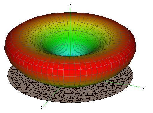
7 V Radiation pattern

8 Monopole antenna From the ground, at a very small height, a λ/4 antenna is place vertically, called monopole antenna. AM, FM applications.


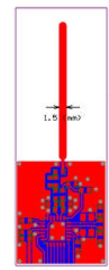
9 Examples Bluetooth dongle 1cm
10 Long wire antennas
11 Long wire antennas - Theory Consider a thin wire of length L is horizontally placed at a height from ground plane. At one end a RF source is connected and other end is terminated by the characteristics impedance of the wire Z 0. When the wire is excited with a sinusoidal signal, the wave should travel along one direction and will not create any standing wave so called Travelling waves. We are gonna see the expression for electric field at a point P - located at a distance of r from the wire and angle of θ with respect to the length of wire. ~ Wave direction h Z 0
12 Travelling wave structure E field The retarded current in the wire shall be described as Where: v=p.c or p=v/c I I m sin t p is the ratio of the wave velocity at the wire to the free space, called Relative phase velocity. Used to vary with the attenuation constant. r C Z v 1 r P z 1 θ Wave direction z Z 0 Z-axis
13 Radiation pattern We can find the radiation pattern as similar to the dipole case, will result: Here, η is wave impedance. E I 0 p sin wl.sin 1 p 2 R 1 p cos 2 pc cos [Krauss]
14 Maxima direction: Also called Elevation angel (θ max, θ m, α, β) θ m or β cos m L

15 For 3λ and 5λ [Krauss]
16 Minor lob directions, Directivity m=2 m=1 m=0 [Balanis]
17 Bidirectional long wire antenna The maxima direction oriented with the direction of wave in the wire, so by introducing wave on both the direction we can introduce Bidirectional radiation. This can be possible by Open circuited long wire or Un-terminated, so called Stand wave antenna. R P θ Wave direction


18 β Vee antennas γ=2β By terminating with Z 0, we can get Uni-directional radiation Design equation: Φ=2 β where β is θ max of single long wire
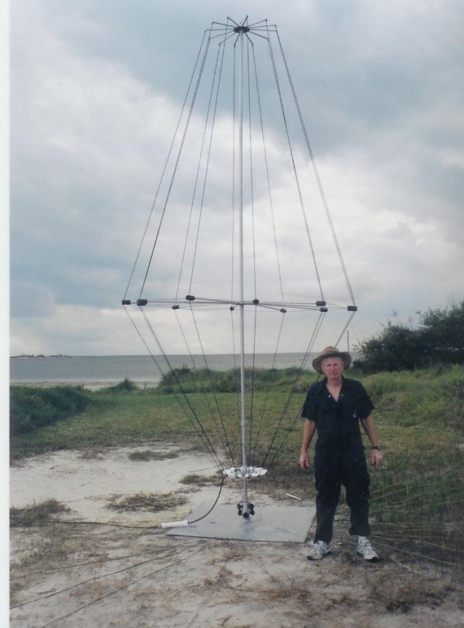
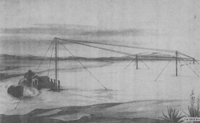
19 Rhombic antenna Based on the principle of Traveling wave and Vee antenna, Rhombic antenna is a very high directive antenna has Diamond or Rhombus shape β

20


21 Working of Rhombic antenna By properly selecting the tilt angle, the rhombic antenna will give additive effect of radiation pattern of each long wire antenna The radiation mechanism is basically depends on two factors: Tilt angle (φ) Height above the ground (h) These are design parameters of antenna Due to ground effect, the maximum radiation is elevated about an angel (β) Z 0 β
22 Design equations of Rhombic antenna BBL field equation: (Bruce, Beck and Lowry 1935) From this equation, we can deduce the condition to get the maximum power direction with respect to height h and length of line L Original Article: About Dr. Bruce, E:
23 Maxima with height
24 Maxima with Length L
25 Design formula Finally, the design formulae are: (also called BBL formula)
26 Design a rhombic antenna to operate at 20MHz when the angle of elevation angle =10 o. o o o sin o L ; h m L 5.715m; h m
27 Numerical Problems and Review Questions Explain about long wire and Rhombic antenna with its radiation pattern Design a rhombic antenna to operate at 20MHz when the angle of elevation angle =10 o. Explain resonant and non-resonant modes of Long Wire Antenna. If we assume the average beamwidth of rhombic antenna as 10 o, then design an antenna system such that it will radiate maximum power over the ranges from 10 o to 40 o for the operating frequency of 10MHz Explain the working of Open circuited long wire antenna and V antenna with radiation pattern
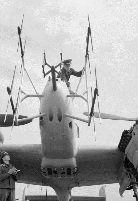
28 Yagi-Uda Antenna A high frequency and high directive Parasitic array antenna

: Application of bacteria foraging algorithm for the design optimization of")
29 Introduction Prof. S. Uda (japan) was invented this antenna by 1927, and collaborated with H. Yagi S. Uda, "High angle radiation of short electric waves". Proceedings of the IRE, vol. 15, pp , May After the invention, more than 40 researcher were studied on the improvement. Latest article (2011): Application of bacteria foraging algorithm for the design optimization of multi-objective Yagi-Uda array Shintaro Uda Hidetsugu Yagi
 effect between the parasitic elements and active element(dipole), the directional properties are improved a high with endfire pattern Reflector: about 5% greater length than")

30 Principle A folded dipole or ordinary half wave dipole is centered between two types of parasitic elements, called: Directors and Reflectors. The coupling (capacitive) effect between the parasitic elements and active element(dipole), the directional properties are improved a high with endfire pattern Reflector: about 5% greater length than the active element, will reflects the power radiation at backward direction. Directors: 5% lesser length than the active element, will create a converging mechanism and increase the directivity along the forward direction. Spacing between the directors and reflector are depending on the optimality, in most of the case, the spacing should from 0.3λ to 0.4λ (at 1927, the spacing was λ/10) 12 to 20 element yagi-uda antennas are optimum and have improved directivity
, but 45 to 60 degree elevated")
31 Radiation properties Basically End-fire radiation pattern, with high directivity (less HPBW) Due to the ground and parasitic element, the pattern maxima at elevation will not be at 90 o (along the axis), but 45 to 60 degree elevated so.
32 Radiation properties We can show that, while increasing the directors, the gain and directivity will improve, however the side lobs will degrade the performance by attracting the noise in unwanted direction.
33 Measurements Forward gain Backward gain (or back gain) Front to Back ratio (diff of F.gain and B.gain) Magnitude of side lobes Input impedance Bandwidth, quality factor

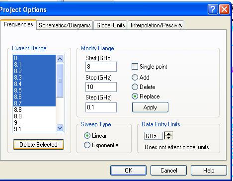
34 Simulation 9GHz Yagi Uda Atleast 1 or 2 λ Dipole=0.5λ Director=0.45λ Reflector=0.53λ
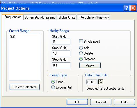
35 f o =8.8GHz Due to inductive effect at dipole and capacitive effect at parasitic elements
36

37 @ 8.8GHz θ max

38 @ 8.8GHz θ max Back gain Approx=25dB Front gain Approx=40dB Front to back ratio=40-25 = 15dB


39 Back gain Approx=17dB Front gain Approx=40dB Front to back ratio=42-17 = 25dB
40 Optimized Design of N-element Yagi-Uda. For the frequency of operation f 0, the λ will be estimated. Reflector: (mostly 1 element) length of 0.5λ with spacing of 0.25 to 0.3λ from dipole. Dipole length (active element): 0.475λ Directors (N-2 elements) 0.405λ with spacing of 0.3 to 0.4λ between each element. To match the dipole, usually the QWT section be utilized.
41
42 Example (from Balanis)

43

44 Various Yagi Uda antenna


45 Smallest Yagi Uda antenna!! Ivan S. Maksymov et al, Optical Yagi-Uda nanoantennas,
Traveling Wave Antennas
 Traveling Wave Antennas Antennas with open-ended wires where the current must go to zero (dipoles, monopoles, etc.) can be characterized as standing wave antennas or resonant antennas. The current on these
Travelling Wave, Broadband, and Frequency Independent Antennas. EE-4382/ Antenna Engineering
 Travelling Wave, Broadband, and Frequency Independent Antennas EE-4382/5306 - Antenna Engineering Outline Traveling Wave Antennas Introduction Traveling Wave Antennas: Long Wire, V Antenna, Rhombic Antenna
UNIT Write short notes on travelling wave antenna? Ans: Travelling Wave Antenna
 UNIT 4 1. Write short notes on travelling wave antenna? Travelling Wave Antenna Travelling wave or non-resonant or aperiodic antennas are those antennas in which there is no reflected wave i.e., standing
1. Explain the basic geometry and elements of Yagi-Uda antenna.
 Benha University Faculty of Engineering- Shoubra Electrical Engineering Department Fourth Year (Communications & Electronics) Final-Term Exam Date: Tuesday 10/5/2016 ECE 424: Lab (4) Duration : 2 Hrs Answer
Resonant Antennas: Wires and Patches
 Resonant Antennas: Wires and Patches Dipole Antennas Antenna 48 Current distribution approximation Un-normalized pattern: and Antenna 49 Radiating power: For half-wave dipole and,, or at exact resonance.
Half-Wave Dipole. Radiation Resistance. Antenna Efficiency
 Antennas Simple Antennas Isotropic radiator is the simplest antenna mathematically Radiates all the power supplied to it, equally in all directions Theoretical only, can t be built Useful as a reference:
Antennas & wave Propagation ASSIGNMENT-I
 Shri Vishnu Engineering College for Women :: Bhimavaram Department of Electronics & Communication Engineering Antennas & wave Propagation 1. Define the terms: i. Antenna Aperture ii. Beam Width iii. Aperture
Yagi Antenna Tutorial. Copyright K7JLT 1
 Yagi Antenna Tutorial Copyright K7JLT Yagi: The Man & Developments In the 920 s two Japanese electrical engineers, Hidetsugu Yagi and Shintaro Uda at Tohoku University in Sendai Japan, investigated ways
EC ANTENNA AND WAVE PROPAGATION
 EC6602 - ANTENNA AND WAVE PROPAGATION FUNDAMENTALS PART-B QUESTION BANK UNIT 1 1. Define the following parameters w.r.t antenna: i. Radiation resistance. ii. Beam area. iii. Radiation intensity. iv. Directivity.
EMG4066:Antennas and Propagation Exp 1:ANTENNAS MMU:FOE. To study the radiation pattern characteristics of various types of antennas.
 OBJECTIVES To study the radiation pattern characteristics of various types of antennas. APPARATUS Microwave Source Rotating Antenna Platform Measurement Interface Transmitting Horn Antenna Dipole and Yagi
Yagi-Uda (Beam) Antenna
 Antenna") Yagi-Uda (Beam) Antenna Gary A. Thiele KD8ZWS (Ex W8RBW) Co-author of Antenna Theory & Design John Wiley & Sons, 1981, 1998, 2013 Yagi-Uda (Beam) Antennas Outline Preliminary Remarks Part I Brief history
Yagi-Uda (Beam) Antenna Gary A. Thiele KD8ZWS (Ex W8RBW) Co-author of Antenna Theory & Design John Wiley & Sons, 1981, 1998, 2013 Yagi-Uda (Beam) Antennas Outline Preliminary Remarks Part I Brief history
Fundamentals of Antennas. Prof. Ely Levine
 Fundamentals of Antennas Prof. Ely Levine levineel@zahav.net.il 1 Chapter 3 Wire Antennas 2 Types of Antennas 3 Isotropic Antenna Isotropic radiator is the simplest antenna mathematically Radiates all
Notes 21 Introduction to Antennas
 ECE 3317 Applied Electromagnetic Waves Prof. David R. Jackson Fall 018 Notes 1 Introduction to Antennas 1 Introduction to Antennas Antennas An antenna is a device that is used to transmit and/or receive
Monopole Antennas. Prof. Girish Kumar Electrical Engineering Department, IIT Bombay. (022)
") Monopole Antennas Prof. Girish Kumar Electrical Engineering Department, IIT Bombay gkumar@ee.iitb.ac.in (022) 2576 7436 Monopole Antenna on Infinite Ground Plane Quarter-wavelength monopole Antenna on
Monopole Antennas Prof. Girish Kumar Electrical Engineering Department, IIT Bombay gkumar@ee.iitb.ac.in (022) 2576 7436 Monopole Antenna on Infinite Ground Plane Quarter-wavelength monopole Antenna on
KINGS COLLEGE OF ENGINEERING DEPARTMENT OF ELECTRONICS AND COMMUNICATION ENGINEERING QUESTION BANK
 KINGS COLLEGE OF ENGINEERING DEPARTMENT OF ELECTRONICS AND COMMUNICATION ENGINEERING QUESTION BANK SUB.NAME : ANTENNAS & WAVE PROPAGATION SUB CODE : EC 1352 YEAR : III SEMESTER : VI UNIT I: ANTENNA FUNDAMENTALS
KINGS COLLEGE OF ENGINEERING. DEPARTMENT OF ELECTRONICS AND COMMUNICATION ENGINEERING Academic Year (Even Sem) QUESTION BANK (AUTT-R2008)
 QUESTION BANK (AUTT-R2008)") KINGS COLLEGE OF ENGINEERING DEPARTMENT OF ELECTRONICS AND COMMUNICATION ENGINEERING Academic Year 2012-2013(Even Sem) QUESTION BANK (AUTT-R2008) SUBJECT CODE /NAME: EC 1352 / ANTENNEA AND WAVE PROPAGATION
KINGS COLLEGE OF ENGINEERING DEPARTMENT OF ELECTRONICS AND COMMUNICATION ENGINEERING Academic Year 2012-2013(Even Sem) QUESTION BANK (AUTT-R2008) SUBJECT CODE /NAME: EC 1352 / ANTENNEA AND WAVE PROPAGATION
DESIGN OF PRINTED YAGI ANTENNA WITH ADDI- TIONAL DRIVEN ELEMENT FOR WLAN APPLICA- TIONS
 Progress In Electromagnetics Research C, Vol. 37, 67 81, 013 DESIGN OF PRINTED YAGI ANTENNA WITH ADDI- TIONAL DRIVEN ELEMENT FOR WLAN APPLICA- TIONS Jafar R. Mohammed * Communication Engineering Department,
Antennas 101 Don t Be a 0.97 db Weakling! Ward Silver NØAX
 Antennas 101 Don t Be a 0.97 db Weakling! Ward Silver NØAX Overview Antennas 101 2 Overview Basic Antennas: Ground Plane / Dipole How Gain and Nulls are Formed How Phased Arrays Work How Yagis Work (simplified)
CHAPTER 8 ANTENNAS 1
 CHAPTER 8 ANTENNAS 1 2 Antennas A good antenna works A bad antenna is a waste of time & money Antenna systems can be very inexpensive and simple They can also be very expensive 3 Antenna Considerations
CHAPTER 5 THEORY AND TYPES OF ANTENNAS. 5.1 Introduction
 CHAPTER 5 THEORY AND TYPES OF ANTENNAS 5.1 Introduction Antenna is an integral part of wireless communication systems, considered as an interface between transmission line and free space [16]. Antenna
Fourth Year Antenna Lab
 Fourth Year Antenna Lab Name : Student ID#: Contents 1 Wire Antennas 1 1.1 Objectives................................................. 1 1.2 Equipments................................................ 1
Development of a noval Switched Beam Antenna for Communications
 Master Thesis Presentation Development of a noval Switched Beam Antenna for Communications By Ashraf Abuelhaija Supervised by Prof. Dr.-Ing. Klaus Solbach Institute of Microwave and RF Technology Department
Broadband Antenna. Broadband Antenna. Chapter 4
 1 Chapter 4 Learning Outcome At the end of this chapter student should able to: To design and evaluate various antenna to meet application requirements for Loops antenna Helix antenna Yagi Uda antenna
HIGH GAIN KOCH FRACTAL DIPOLE YAGI-UDA ANTENNA FOR S AND X BAND APPLICATION
 HIGH GAIN KOCH FRACTAL DIPOLE YAGI-UDA ANTENNA FOR S AND X BAND APPLICATION Rajeev Kumar 1, R Radhakrishnan 2 1,2 Department of Theoretical Physics, University of Madras, (India) ABSTRACT In this study,
It is clear in Figures a and b that in some very specific directions there are zeros, or nulls, in the pattern indicating no radiation.
 Unit 2 - Point Sources and Arrays Radiation pattern: The radiation pattern of antenna is a representation (pictorial or mathematical) of the distribution of the power out-flowing (radiated) from the antenna
DEPARTMENT OF ELECTRONICS & COMMUNICATION ENGINEERING SUBJECT NAME:
 Chendu College of Engineering & Technology (Approved by AICTE, New Delhi and Affiliated to Anna University) Zamin Endathur, Madurantakam, Kancheepuram, District 603311. DEPARTMENT OF ELECTRONICS & COMMUNICATION
Antenna Engineering Lecture 3: Basic Antenna Parameters
 Antenna Engineering Lecture 3: Basic Antenna Parameters ELC 405a Fall 2011 Department of Electronics and Communications Engineering Faculty of Engineering Cairo University 2 Outline 1 Radiation Pattern
Large Loop Antennas. Special thanks to graduate students of ECSE 593 class, Winter 2007: Yasha Khatamian, Lin Han, Ruiming Chen
 Large Loop Antennas Special thanks to graduate students of ECSE 593 class, Winter 2007: Yasha Khatamian, Lin Han, Ruiming Chen McGill University, ECSE 405 Antennas, Fall 2009, Prof. M. Popovic 1. History
BHARATHIDASAN ENGINEERING COLLEGE NATTARAMPALLI Frequently Asked Questions (FAQ) Unit 1
 Unit 1") BHARATHIDASAN ENGINEERING COLLEGE NATTARAMPALLI 635854 Frequently Asked Questions (FAQ) Unit 1 Degree / Branch : B.E / ECE Sem / Year : 3 rd / 6 th Sub Name : Antennas & Wave Propagation Sub Code : EC6602
BHARATHIDASAN ENGINEERING COLLEGE NATTARAMPALLI 635854 Frequently Asked Questions (FAQ) Unit 1 Degree / Branch : B.E / ECE Sem / Year : 3 rd / 6 th Sub Name : Antennas & Wave Propagation Sub Code : EC6602
UNIT-3. Ans: Arrays of two point sources with equal amplitude and opposite phase:
 `` UNIT-3 1. Derive the field components and draw the field pattern for two point source with spacing of λ/2 and fed with current of equal n magnitude but out of phase by 180 0? Ans: Arrays of two point
General License Class Chapter 6 - Antennas. Bob KA9BHD Eric K9VIC
 General License Class Chapter 6 - Antennas Bob KA9BHD Eric K9VIC Learning Objectives Teach you enough to get all the antenna questions right during the VE Session Learn a few things from you about antennas
Final Examination. 22 April 2013, 9:30 12:00. Examiner: Prof. Sean V. Hum. All non-programmable electronic calculators are allowed.
 UNIVERSITY OF TORONTO FACULTY OF APPLIED SCIENCE AND ENGINEERING The Edward S. Rogers Sr. Department of Electrical and Computer Engineering ECE 422H1S RADIO AND MICROWAVE WIRELESS SYSTEMS Final Examination
ANTENNAS. I will mostly be talking about transmission. Keep in mind though, whatever is said about transmission is true of reception.
 Reading 37 Ron Bertrand VK2DQ http://www.radioelectronicschool.com ANTENNAS The purpose of an antenna is to receive and/or transmit electromagnetic radiation. When the antenna is not connected directly
YAGI-UDA DESIGN OF U.H.F BAND AERIAL TO SUIT LOCAL TV STATIONS
 YAGI-UDA DESIGN OF U.H.F BAND AERIAL TO SUIT LOCAL TV STATIONS PROJECT INDEX: PRJ 079 Presented By: GITAU SIMON WAWERU F17/8261/2004 Supervisor: Mr. S.L OGABA Examiner: Mr. OMBURA Objective The main objective
Master Thesis. Mobile Phone Antenna Modelling. Umut Bulus. Supervised by Prof. Dr.-Ing. K. Solbach
 Master Thesis Mobile Phone Antenna Modelling Umut Bulus Supervised by Prof. Dr.-Ing. K. Solbach 2.3.28 Contents Introduction Theoretical Background Antenna Measurements on Different PCB Variations Investigation
7. Experiment K: Wave Propagation
 7. Experiment K: Wave Propagation This laboratory will be based upon observing standing waves in three different ways, through coaxial cables, in free space and in a waveguide. You will also observe some
ELEC 477/677L Wireless System Design Lab Spring 2014
 ELEC 477/677L Wireless System Design Lab Spring 2014 Lab #5: Yagi-Uda Antenna Design Using EZNEC Introduction There are many situations, such as in point-to-point communication, where highly directional
"Natural" Antennas. Mr. Robert Marcus, PE, NCE Dr. Bruce C. Gabrielson, NCE. Security Engineering Services, Inc. PO Box 550 Chesapeake Beach, MD 20732
 Published and presented: AFCEA TEMPEST Training Course, Burke, VA, 1992 Introduction "Natural" Antennas Mr. Robert Marcus, PE, NCE Dr. Bruce C. Gabrielson, NCE Security Engineering Services, Inc. PO Box
Chapter 6 Broadband Antenna. 1. Loops antenna 2. Heliksantenna 3. Yagi uda antenna
 Chapter 6 Broadband Antenna 1. Loops antenna 2. Heliksantenna 3. Yagi uda antenna 1 Design A broadband antenna should have acceptable performance (determined by its pattern, gain and/or feed-point impedance)
Physical Yagi-Uda Antenna
 Physical Yagi-Uda Antenna Tanner Gore, Keenan Rusk, Bijan Tehrani I. INTRODUCTION Our group objective was to design, analyze, and fabricate a directional antenna. This task had five major objectives. Resonate
CHAPTER 5 PRINTED FLARED DIPOLE ANTENNA
 CHAPTER 5 PRINTED FLARED DIPOLE ANTENNA 5.1 INTRODUCTION This chapter deals with the design of L-band printed dipole antenna (operating frequency of 1060 MHz). A study is carried out to obtain 40 % impedance
Chapter 6 Antenna Basics. Dipoles, Ground-planes, and Wires Directional Antennas Feed Lines
 Chapter 6 Antenna Basics Dipoles, Ground-planes, and Wires Directional Antennas Feed Lines Some General Rules Bigger is better. (Most of the time) Higher is better. (Most of the time) Lower SWR is better.
Dipole Antennas. Prof. Girish Kumar Electrical Engineering Department, IIT Bombay. (022)
") Dipole Antennas Prof. Girish Kumar Electrical Engineering Department, IIT Bombay gkumar@ee.iitb.ac.in (022) 2576 7436 Infinitesimal Dipole An infinitesimally small current element is called the Hertz Dipole
Dipole Antennas Prof. Girish Kumar Electrical Engineering Department, IIT Bombay gkumar@ee.iitb.ac.in (022) 2576 7436 Infinitesimal Dipole An infinitesimally small current element is called the Hertz Dipole
RADIATION PATTERNS. The half-power (-3 db) beamwidth is a measure of the directivity of the antenna.
 beamwidth is a measure of the directivity of the antenna.") RADIATION PATTERNS The radiation pattern is a graphical depiction of the relative field strength transmitted from or received by the antenna. Antenna radiation patterns are taken at one frequency, one
RADIATION PATTERNS The radiation pattern is a graphical depiction of the relative field strength transmitted from or received by the antenna. Antenna radiation patterns are taken at one frequency, one
Antenna Theory EELE 5445
 Antenna Theory EELE 5445 Lecture 6: Dipole Antenna Dr. Mohamed Ouda Electrical Engineering Department Islamic University of Gaza 2013 The dipole and the monopole The dipole and the monopole are arguably
Antenna? What s That? Chet Thayer WA3I
 Antenna? What s That? Chet Thayer WA3I Space: The Final Frontier Empty Space (-Time) Four dimensional region that holds everything Is Permeable : It requires energy to set up a magnetic field within it.
RECOMMENDATION ITU-R BS.80-3 * Transmitting antennas in HF broadcasting
 Rec. ITU-R BS.80-3 1 RECOMMENDATION ITU-R BS.80-3 * Transmitting antennas in HF broadcasting (1951-1978-1986-1990) The ITU Radiocommunication Assembly, considering a) that a directional transmitting antenna
ANTENNAS AND WAVE PROPAGATION EC602
 ANTENNAS AND WAVE PROPAGATION EC602 B.Tech Electronics & Communication Engineering, Semester VI INSTITUTE OF TECHNOLOGY NIRMA UNIVERSITY 1 Lesson Planning (L-3,P-2,C-4) Chapter No. Name Hours 1. Basic
Antenna Fundamentals. Microwave Engineering EE 172. Dr. Ray Kwok
 Antenna Fundamentals Microwave Engineering EE 172 Dr. Ray Kwok Reference Antenna Theory and Design Warran Stutzman, Gary Thiele, Wiley & Sons (1981) Microstrip Antennas Bahl & Bhartia, Artech House (1980)
Research Article Yagi Array of Microstrip Quarter-Wave Patch Antennas with Microstrip Lines Coupling
 Antennas and Propagation Volume 214, Article ID 12362, 7 pages http://dx.doi.org/1.1155/214/12362 Research Article Yagi Array of Microstrip Quarter-Wave Patch Antennas with Microstrip Lines Coupling Juhua
DESIGN CONSIDERATION OF ARRAYS FOR THE STUDIES OF RADIATION PATTERN OF LOG PERIODIC DIPOLE ARRAY ANTENNA AT DIFFERENT FREQUENCIES
 DESIGN CONSIDERATION OF ARRAYS FOR THE STUDIES OF RADIATION PATTERN OF LOG PERIODIC DIPOLE ARRAY ANTENNA AT DIFFERENT FREQUENCIES 1 Atanu Nag, 2 Kanchan Acharjee, 3 Kausturi Chatterjee, 4 Swastika Banerjee
Designing and building a Yagi-Uda Antenna Array
 2015; 2(2): 296-301 IJMRD 2015; 2(2): 296-301 www.allsubjectjournal.com Received: 17-12-2014 Accepted: 26-01-2015 E-ISSN: 2349-4182 P-ISSN: 2349-5979 Impact factor: 3.762 Abdullah Alshahrani School of
Antenna Fundamentals
 HTEL 104 Antenna Fundamentals The antenna is the essential link between free space and the transmitter or receiver. As such, it plays an essential part in determining the characteristics of the complete
Small Array Design Using Parasitic Superdirective Antennas
 Small Array Design Using Parasitic Superdirective Antennas Abdullah Haskou, Sylvain Collardey, Ala Sharaiha To cite this version: Abdullah Haskou, Sylvain Collardey, Ala Sharaiha. Small Array Design Using
The Basics of Patch Antennas, Updated
 The Basics of Patch Antennas, Updated By D. Orban and G.J.K. Moernaut, Orban Microwave Products www.orbanmicrowave.com Introduction This article introduces the basic concepts of patch antennas. We use
Antennas Prof. Girish Kumar Department of Electrical Engineering Indian Institute of Technology, Bombay. Module 2 Lecture - 10 Dipole Antennas-III
 Antennas Prof. Girish Kumar Department of Electrical Engineering Indian Institute of Technology, Bombay Module 2 Lecture - 10 Dipole Antennas-III Hello, and welcome to todays lecture on Dipole Antenna.
Range Considerations for RF Networks
 TI Technology Days 2010 Range Considerations for RF Networks Richard Wallace Abstract The antenna can be one of the most daunting components of wireless designs. Most information available relates to large
UNIVERSITI MALAYSIA PERLIS
 UNIVERSITI MALAYSIA PERLIS SCHOOL OF COMPUTER & COMMUNICATIONS ENGINEERING EKT 341 LABORATORY MODULE LAB 2 Antenna Characteristic 1 Measurement of Radiation Pattern, Gain, VSWR, input impedance and reflection
Antenna Fundamentals Basics antenna theory and concepts
 Antenna Fundamentals Basics antenna theory and concepts M. Haridim Brno University of Technology, Brno February 2017 1 Topics What is antenna Antenna types Antenna parameters: radiation pattern, directivity,
Antennas & Transmission Lines
 Antennas & Transmission Lines Network Startup Resource Center www.nsrc.org These materials are licensed under the Creative Commons Attribution-NonCommercial 4.0 International license (http://creativecommons.org/licenses/by-nc/4.0/)
Research Article Very Compact and Broadband Active Antenna for VHF Band Applications
 Antennas and Propagation Volume 2012, Article ID 193716, 4 pages doi:10.1155/2012/193716 Research Article Very Compact and Broadband Active Antenna for VHF Band Applications Y. Taachouche, F. Colombel,
INSTITUTE OF AERONAUTICAL ENGINEERING Dundigal, Hyderabad ELECTRONICS AND COMMUNIACTION ENGINEERING QUESTION BANK
 INSTITUTE OF AERONAUTICAL ENGINEERING Dundigal, Hyderabad - 500 04 ELECTRONICS AND COMMUNIACTION ENGINEERING QUESTION BANK Course Name : Antennas and Wave Propagation (AWP) Course Code : A50418 Class :
Yagi beam antennas CHAPTER 10 COMPOSITION OF A BEAM ANTENNA _
 CHAPTER 10 Yagi beam antennas The Yagi beam antenna (more correctly, the Yagi Uda antenna, after both of the designers of Tohoku University in Japan 1926) is unidirectional. It can be vertically polarized
ECE 4370: Antenna Engineering TEST 1 (Fall 2011)
") Name: GTID: ECE 4370: Antenna Engineering TEST 1 (Fall 2011) Please read all instructions before continuing with the test. This is a closed notes, closed book, closed friend, open mind test. On your desk
Name: GTID: ECE 4370: Antenna Engineering TEST 1 (Fall 2011) Please read all instructions before continuing with the test. This is a closed notes, closed book, closed friend, open mind test. On your desk
Loop and Slot Antennas
 Loop and Slot Antennas Prof. Girish Kumar Electrical Engineering Department, IIT Bombay gkumar@ee.iitb.ac.in (022) 2576 7436 Loop Antenna Loop antennas can have circular, rectangular, triangular or any
S.R.M. Institute of Science & Technology Deemed University School of Electronics & Communication Engineering
 S.R.M. Institute of Science & Technology Deemed University School of Electronics & Communication Engineering Question Bank Subject Code : EC401 Subject Name : Antennas and Wave Propagation Year & Sem :
ECE 4370: Antenna Engineering TEST 2 (Fall 2012)
") Name: GTID: ECE 4370: Antenna Engineering TEST 2 (Fall 2012) Please read all instructions before continuing with the test. This is a closed notes, closed book, closed friend, open mind test. On your desk
Name: GTID: ECE 4370: Antenna Engineering TEST 2 (Fall 2012) Please read all instructions before continuing with the test. This is a closed notes, closed book, closed friend, open mind test. On your desk
American International Journal of Research in Science, Technology, Engineering & Mathematics
 American International Journal of Research in Science, Technology, Engineering & Mathematics Available online at http://www.iasir.net ISSN (Print): 2328-3491, ISSN (Online): 2328-3580, ISSN (CD-ROM): 2328-3629
IMPROVEMENT OF YAGI UDA ANTENNA RADIATION PATTERN
 International Journal of Mechanical Engineering and Technology (IJMET) Volume 8, Issue 7, July 2017, pp. 636 641, Article ID: IJMET_08_07_071 Available online at http://www.iaeme.com/ijmet/issues.asp?jtype=ijmet&vtype=8&itype=7
Antenna & Propagation. Antenna Parameters
 For updated version, please click on http://ocw.ump.edu.my Antenna & Propagation Antenna Parameters by Nor Hadzfizah Binti Mohd Radi Faculty of Electric & Electronics Engineering hadzfizah@ump.edu.my Chapter
Chapter 7 Design of the UWB Fractal Antenna
 Chapter 7 Design of the UWB Fractal Antenna 7.1 Introduction F ractal antennas are recognized as a good option to obtain miniaturization and multiband characteristics. These characteristics are achieved
Dr. John S. Seybold. November 9, IEEE Melbourne COM/SP AP/MTT Chapters
 Antennas Dr. John S. Seybold November 9, 004 IEEE Melbourne COM/SP AP/MTT Chapters Introduction The antenna is the air interface of a communication system An antenna is an electrical conductor or system
Characteristics of Biconical Antennas Used for EMC Measurements
 Advance Topics in Electromagnetic Compatibility Characteristics of Biconical Antennas Used for EMC Measurements Mohsen Koohestani koohestani.mohsen@epfl.ch Outline State-of-the-art of EMC Antennas Biconical
MICROWAVE ENGINEERING MCQs
 MICROWAVE ENGINEERING MCQs 1) If an antenna draws 12 A current and radiates 4 kw, then what will be its radiation resistance? a. 22.22 ohm b. 27.77 ohm c. 33.33 ohm d. 39.77 ohm 2) Which mode of radiation
Research Article Circularly Polarized Microstrip Yagi Array Antenna with Wide Beamwidth and High Front-to-Back Ratio
 International Journal of Antennas and Propagation Volume 21, Article ID 275, pages http://dx.doi.org/1.15/21/275 Research Article Circularly Polarized Microstrip Yagi Array Antenna with Wide Beamwidth
An Introduction to Antennas
 May 11, 010 An Introduction to Antennas 1 Outline Antenna definition Main parameters of an antenna Types of antennas Antenna radiation (oynting vector) Radiation pattern Far-field distance, directivity,
SI TECHNICAL 2018 UNIT IV QUESTION BANK
 SI TECHNICAL 2018 UNIT IV QUESTION BANK 1. In what range of frequencies are most omnidirectional horizontally polarized antennas used? A. VHF, UHF B. VLF, LF C. SH, EHF D. MF, HF 2. If the current ratios
DESIGN AND SIMULATION OF CYLINDRICAL AND SHEET CORNER REFLECTOR YAGI UDA ANTENNAS FOR AMATEUR RADIO APPLICATION
 DESIGN AND SIMULATION OF CYLINDRICAL AND SHEET CORNER REFLECTOR YAGI UDA ANTENNAS FOR AMATEUR RADIO APPLICATION Akella Jharesh, K. Ch. Sri Kavya and Sarat K. Kotamraju Department of Electronics and Communication
Antenna Theory and Design
 Antenna Theory and Design Antenna Theory and Design Associate Professor: WANG Junjun 王珺珺 School of Electronic and Information Engineering, Beihang University wangjunjun@buaa.edu.cn 13426405497 Chapter
Research Article Beam Tilt-Angle Estimation for Monopole End-Fire Array Mounted on a Finite Ground Plane
 Antennas and Propagation Volume 215, Article ID 351439, 8 pages http://dx.doi.org/1.1155/215/351439 Research Article Beam Tilt-Angle Estimation for Monopole End-Fire Array Mounted on a Finite Ground Plane
Antennas Prof. Girish Kumar Department of Electrical Engineering India Institute of Technology, Bombay. Module - 1 Lecture - 1 Antennas Introduction-I
 Antennas Prof. Girish Kumar Department of Electrical Engineering India Institute of Technology, Bombay Module - 1 Lecture - 1 Antennas Introduction-I Hello everyone. Welcome to the exciting world of antennas.
Transforms and electrical signal into a propagating electromagnetic wave OR vise versa. - Transducer goes both ways. TX and RX antennas have
 Gary Rondeau AF7NX Transforms and electrical signal into a propagating electromagnetic wave OR vise versa. - Transducer goes both ways. TX and RX antennas have different jobs. For TX want to generate as
UNIT Explain the radiation from two-wire. Ans: Radiation from Two wire
 UNIT 1 1. Explain the radiation from two-wire. Radiation from Two wire Figure1.1.1 shows a voltage source connected two-wire transmission line which is further connected to an antenna. An electric field
ANTENNA THEORY. Analysis and Design. CONSTANTINE A. BALANIS Arizona State University. JOHN WILEY & SONS New York Chichester Brisbane Toronto Singapore
 ANTENNA THEORY Analysis and Design CONSTANTINE A. BALANIS Arizona State University JOHN WILEY & SONS New York Chichester Brisbane Toronto Singapore Contents Preface xv Chapter 1 Antennas 1 1.1 Introduction
Antenna Trainer EAN. Technical Teaching Equipment INTRODUCTION
 Antenna Trainer EAN Technical Teaching Equipment Products Products range Units 3.-Communications INTRODUCTION Antennas are the main element of aerial communications. They are the transition between a transmission
ECE 4370: Antenna Engineering TEST 2 (Spring 2015)
") Name: GTID: ECE 4370: Antenna Engineering TEST 2 (Spring 205) Please read all instructions before continuing with the test. This is a closed notes, closed book, closed friend, open mind test. On our desk
Name: GTID: ECE 4370: Antenna Engineering TEST 2 (Spring 205) Please read all instructions before continuing with the test. This is a closed notes, closed book, closed friend, open mind test. On our desk
Antenna Arrays. EE-4382/ Antenna Engineering
 Antenna Arrays EE-4382/5306 - Antenna Engineering Outline Introduction Two Element Array Rectangular-to-Polar Graphical Solution N-Element Linear Array: Uniform Spacing and Amplitude Theory of N-Element
Cylindrical Conformal Microstrip Yagi Array with Endfire Radiation and Vertical Polarization
 Forum for Electromagnetic Research Methods and Application Technologies (FERMAT) Cylindrical Conformal Microstrip Yagi Array with Endfire Radiation and Vertical Polarization Yulong Xia 1,2, Liangmengcheng
A Beam Switching Planar Yagi-patch Array for Automotive Applications
 PIERS ONLINE, VOL. 6, NO. 4, 21 35 A Beam Switching Planar Yagi-patch Array for Automotive Applications Shao-En Hsu, Wen-Jiao Liao, Wei-Han Lee, and Shih-Hsiung Chang Department of Electrical Engineering,
Antenna Theory. Introduction
 1 Introduction Antenna Theory Antennas are device that designed to radiate electromagnetic energy efficiently in a prescribed manner. It is the current distributions on the antennas that produce the radiation.
Rec. ITU-R F RECOMMENDATION ITU-R F *
 Rec. ITU-R F.162-3 1 RECOMMENDATION ITU-R F.162-3 * Rec. ITU-R F.162-3 USE OF DIRECTIONAL TRANSMITTING ANTENNAS IN THE FIXED SERVICE OPERATING IN BANDS BELOW ABOUT 30 MHz (Question 150/9) (1953-1956-1966-1970-1992)
Antenna & Wave Propagation (Subject Code: 7EC1)
") COMPUCOM INSTITUTE OF TECHNOLOGY & MANAGEMENT, JAIPUR (DEPARTMENT OF ELECTRONICS & COMMUNICATION) Notes Antenna & Wave Propagation (Subject Code: 7EC1) Prepared By: Raj Kumar Jain Class: B. Tech. IV Year,
COMPUCOM INSTITUTE OF TECHNOLOGY & MANAGEMENT, JAIPUR (DEPARTMENT OF ELECTRONICS & COMMUNICATION) Notes Antenna & Wave Propagation (Subject Code: 7EC1) Prepared By: Raj Kumar Jain Class: B. Tech. IV Year,
DESIGN OF PASSIVE RETRANSMITTING SYSTEM
 76 DESIGN OF PASSIVE RETRANSMITTING SYSTEM FOR CELLULAR COMMUNICATION Juliane Iten Chaves, Anton Gora Junior, and José Ricardo Descardeci Department of Electrical Engineering, Federal University of Parana-UFPR
Loop Antennas for HF Reception
 COMMUNICATIONS 74 CONFERENCE BRIGHTON Wednesday, June 5 1974 Session 5, Equipment Design Paper 5.3: Loop Antennas for HF Reception Contributed by: B.S.Collins, C & S Antennas Ltd., Knight Road, Rochester,
Antennas Demystified Antennas in Emergency Communications. Scott Honaker N7SS
 Antennas Demystified Antennas in Emergency Communications Scott Honaker N7SS Importance of Antennas Antennas are more important than the radio A $5000 TV with rabbit ears will have a lousy picture Antennas
ANTENNAS 101 An Introduction to Antennas for Ham Radio. Lee KD4RE
 ANTENNAS 101 An Introduction to Antennas for Ham Radio Lee KD4RE Prepared for Presentation at the Vienna Wireless Society, 13 January 2017 So What is an Antenna Anyway? We are all familiar with wire antennas
R. Zhang, G. Fu, Z.-Y. Zhang, and Q.-X. Wang Key Laboratory of Antennas and Microwave Technology Xidian University, Xi an, Shaanxi , China
 Progress In Electromagnetics Research Letters, Vol. 2, 137 145, 211 A WIDEBAND PLANAR DIPOLE ANTENNA WITH PARASITIC PATCHES R. Zhang, G. Fu, Z.-Y. Zhang, and Q.-X. Wang Key Laboratory of Antennas and Microwave
stacking broadside collinear
 stacking broadside collinear There are three primary types of arrays, collinear, broadside, and endfire. Collinear is pronounced co-linear, and we may think it is spelled colinear, but the correct spelling
Coupled Sectorial Loop Antenna (CSLA) for Ultra Wideband Applications
 for Ultra Wideband Applications") Coupled Sectorial Loop Antenna (CSLA) for Ultra Wideband Applications N. Behdad and K. Sarabandi Presented by Nader Behdad at Antenna Application Symposium, Monticello, IL, Sep 2004 Email: behdad@ieee.org
Coupled Sectorial Loop Antenna (CSLA) for Ultra Wideband Applications N. Behdad and K. Sarabandi Presented by Nader Behdad at Antenna Application Symposium, Monticello, IL, Sep 2004 Email: behdad@ieee.org
4G MIMO ANTENNA DESIGN & Verification
 4G MIMO ANTENNA DESIGN & Verification Using Genesys And Momentum GX To Develop MIMO Antennas Agenda 4G Wireless Technology Review Of Patch Technology Review Of Antenna Terminology Design Procedure In Genesys