2.0 PROJECT DESCRIPTION
|
|
|
- Roger Burke
- 6 years ago
- Views:
Transcription
1 2.0 PROJECT DESCRIPTION 2.1 INTRODUCTION Overview of Manitoba Hydro s Transmission System Manitoba is heavily reliant on hydroelectricity, approximately 70% of which is generated in plants along the Nelson River in the form of alternating current (ac). A small portion of this generation is fed directly to the northern ac transmission system to serve northern areas. The remainder is connected to the Northern ac Collector Transmission System (Map 2-1). This collector system connects the generating stations on the Nelson River to the dc converter stations at Radisson and Henday. Two HVdc lines (Bipole I and II) connect the Radisson and Henday Converter Stations in northern Manitoba to the Dorsey Converter Station, located near Winnipeg. From there, the electricity is distributed throughout much of southern Manitoba through the southern ac transmission system (Map 2-1). The remaining hydraulic generation is supplied by generating stations on the Winnipeg River, at Grand Rapids on the Saskatchewan River and at Jenpeg on the Upper Nelson River, north of Lake Winnipeg. Generation outlet transmission facilities for the Winnipeg River plants consist of 115 kv ac transmission lines that connect to the southern account transmission system and are not converted to dc due to short distances to stations (Map 2-1). When operating at full capacity, Manitoba Hydro s hydraulic generation system produces more power than required for today s domestic consumption. High-voltage ac transmission facilities interconnected to Saskatchewan, Ontario and the US make it possible to export power to those jurisdictions. Interconnected transmission facilities also allow Manitoba Hydro to import power during periods of drought and periods during which demand in Manitoba exceeds the supply Manitoba Hydro can generate, thereby strengthening the reliability of the provincial electric system. 2.2 PROJECT COMPONENT OVERVIEW The Keeyask Transmission Project will consist of the following: Construction Power Transmission Line and Construction Power Station. Four Unit Transmission Lines that originate at the Keeyask Generating Station and terminate at a new Keeyask Switching Station. Keeyask Switching Station. KEEYASK TRANSMISSION PROJECT EA REPORT CHAPTER 2 PROJECT DESCRIPTION 2-1
2 Three Generation Outlet Transmission (GOT) Lines link the Keeyask Switching Station to the northern collector system, terminating at the Radisson Converter Station. Radisson Converter Station Upgrades Construction Power Transmission Line and Station The Project will include a new Construction Power Transmission Line (138 kv and approximately 22 km long) from the existing 138 kv KN36 transmission line to a new 138 kv to kv station to be located north of the proposed Keeyask Generation Station. The purpose of the Construction Power Transmission Line and Construction Power Station is to provide power to construct the Keeyask Generation Project. After the Keeyask Generating Station is constructed, the Construction Power Transmission Line will be left in place, as will a portion of the Construction Power Station, to provide a contingency function for a black start emergency backup to diesel generation units at the Generating Station Unit Transmission Lines Four 138 kv ac ttransmission lines (KE1 to 4), called the Unit Transmission Lines, will transmit power from the seven generators located at the Keeyask Generating Station to the new Keeyask Switching Station. Three lines will be double circuit and one line single circuit to accept power from the seven Generating Station turbines. The four lines, each approximately 4 km long, will be located in a single corridor Keeyask Switching Station A new Keeyask Switching Station will accept power from the Generating Station via the four Unit Transmission Lines and transfer that power to three Generation Outlet Transmission lines. The switching station will be located on the south side of the Nelson River. The purpose of the switching station is to provide the terminal facilities for the electrical connection to the Keeyask Generating Station, and to provide flexibility in switching load between incoming Unit Transmission Lines from the Generating Station to the Generation Outlet Transmission Lines going to Radisson Converter Station Generation Outlet Transmission Lines Three 138 kv ac Transmission Lines will transmit power from the Keeyask Switching Station to the existing Radisson Converter Station 138 kv ac switchyard. Known as the Generation Outlet Transmission (GOT) Lines, the three lines, each approximately 38 km long, will be located along a single route. Manitoba Hydro plans to build one of these GOT lines called KR1 to serve as a backup construction power line during construction. After Project construction, the KR1 KEEYASK TRANSMISSION PROJECT EA REPORT CHAPTER 2 PROJECT DESCRIPTION 2-2
3 Transmission Line will be partially salvaged and re-terminated at the Keeyask Switching Station and utilized as a Generation Outlet Transmission Line Radisson Converter Station Upgrades The existing Radisson Converter Station will be upgraded in two stages, as follows: Stage I: The addition of a 138 kv breaker to accommodate the initial new Generation Outlet Transmission line (KR1) from the Keeyask Switching Station. Stage II: The addition of equipment including a 138 kv bay (Bay 1) complete with four 138 kv breakers and associated equipment for the termination of two additional GOT lines (KR2 and KR3) from the Keeyask Switching Station. KR2 and KR3 will enter the west side of the Radisson Converter Station and proceed underground around the station and finally terminate to Bay Preferred Routes and Station Sites The Preferred Routes and Station Sites are shown on Map 2-2 for the construction and operation phases, respectively. 2.3 TRANSMISSION LINES TECHNICAL DESCRIPTION The following sections provide a more detailed life cycle description of the transmission line components included in the Keeyask Transmission Project. The description includes the construction, operation and maintenance phases of each component, as well as prospective decommissioning. The current Project description information is based on preliminary design and on Manitoba Hydro standards with respect to design and construction, operation and maintenance, and decommissioning. Project development will also adhere to applicable North American Electric Reliability Corporation/Midwest Reliability Organization/Midwest Independent System Operator criteria and Canadian Standard Association (CSA) standards. Subject to approval requirements, details of the final design may vary from the preliminary design on the basis of field conditions, contract requirements and contractor implementation Unit Transmission Lines Four 138 kv ac Unit Transmission lines will transmit power from the seven generators located at the Keeyask Generating Station to the new Keeyask Switching Station. The four lines, each approximately 4 km long, will be located in a single 265-m-wide corridor. Figure 2-1 illustrates a typical cross-section for the Unit Transmission Lines. KEEYASK TRANSMISSION PROJECT EA REPORT CHAPTER 2 PROJECT DESCRIPTION 2-3
4
5 Refer to Section A-A on Map 2-3 Figure 2-1: Typical 138 kv Unit Transmission Lines Right-of-Way
6
7 Structure Design and Location Based on prior design experience in northern Manitoba, guyed lattice steel structures have been identified as the preliminary design standard for straight (tangent) sections of the transmission lines. Guyed structures provide flexibility for tower construction and maintenance in difficult foundation and terrain conditions. Self-supporting lattice steel structures will be used for all angle or dead-end tower locations. The conceptual design for a typical guyed lattice suspension structure is illustrated in Figure 2-2. The structure is based on a single point foundation, stabilized by four guy wires placed diagonally to the route of the line. The tangent structures will be approximately 38 m in height. Taller structures with larger footprints will be used where warranted by land use or conditions. Conceptual design for a typical lattice angle anchor structure is illustrated in Figure 2-3. The structure has four legs requiring individual foundations and a footprint approximately 15 m square. The typical structure height is approximately 30 m. The average span between structures will be approximately 420 m, resulting in approximately 2.4 structures per kilometre. Additional detail respecting span length and tower placement is provided in Section Conductors and Insulators The structures for the Unit Transmission Lines will carry a three-phase 138 kv ac circuit consisting of three Aluminium Conductor Steel Reinforced phase conductors. The specified phase conductor is a single aluminum conductor steel reinforced conductor, 37.2 mm in diameter. The conductors will be insulated from the structures by insulator strings consisting of ceramic insulator bells attached to the crossarms of the structures using insulator string assemblies. Conductor clearances are discussed in Section Overhead Ground Wires Two galvanized steel strand ground conductors having an overall diameter of 9 mm (approximately 0.34 in.) will be strung between the two peaks of the structures to provide lightning protection Switchyard Terminations Unit Transmission Lines will be terminated into the 138 kv Intermediate Bus Structure at the Keeyask Switching Station. KEEYASK TRANSMISSION PROJECT EA REPORT CHAPTER 2 PROJECT DESCRIPTION 2-4
8

9 Figure 2-2: Typical Guyed Lattice Suspension Structure

10 Figure 2-3: Typical Lattice Angle Anchor Structure
11 2.3.2 Generation Outlet Transmission Lines Three Generation Outlet Transmission Lines (GOT KR1 to 3) will transmit power from the 138 kv ac switchyard at the Keeyask Switching Station to the 138 kv ac Switchyard at the existing Radisson Converter Station. The three lines will typically be located in a single 200-mwide corridor about 38 km long (Figure 2-4); however, the width and configuration of the three lines in the corridor will vary, as described in Section Manitoba Hydro is proposing to prebuild one (KR1) of the three GOT lines from the Radisson Converter Station to the Keeyask Construction Power Station, as a source of backup construction power during the construction of the Keeyask Generation Station Project. Once construction of the generating station is complete, a portion of KR1 from the Construction Power Station back to the Keeyask Switching Station will be salvaged, and KR1 will be terminated into this Switching Station. The additional GOT lines (KR2 and KR3) will be built from the existing Radisson Converter Station 138 ac switchyard to the new Keeyask Switching Station Structure Design and Location Based on prior design experience in northern Manitoba, guyed lattice steel structures have been identified as the preliminary design standard for straight (tangent) sections of the transmission lines. Guyed structures provide flexibility for tower construction and maintenance in difficult foundation and terrain conditions. Self-supporting lattice steel structures will be used for all angle or dead-end tower locations. The conceptual design for a typical guyed lattice suspension structure is illustrated in Figure 2-2. The structure is based on a single point foundation, stabilized by four guy wires placed diagonally to the route of the line. The tangent structures will be approximately 38 m in height. Taller structures with larger footprints will be used where warranted by land use or conditions. The conceptual design for a typical lattice angle anchor structure is illustrated in Figure 2-3. The structure has four legs requiring individual foundations and a footprint of approximately 13.7 m 2 square. The typical structure height is approximately 30 m. The average span between structures will be approximately 470 m, resulting in approximately 2.1 structures per kilometre. Additional detail respecting span length and tower placement is provided in Section Conductors and Insulators The structures for the Generation Outlet Transmission Lines will carry a three-phase 138 kv ac circuit consisting of three Aluminum Conductor Steel Reinforced phase conductors. The specified phase conductor is a single aluminum conductor steel reinforced conductor, 39.3 mm (1.55 in.) in diameter. The conductors will be insulated from the structures by insulator KEEYASK TRANSMISSION PROJECT EA REPORT CHAPTER 2 PROJECT DESCRIPTION 2-5
12
13 Figure 2-4: Typical Cross Section of Generation Outlet Transmission Line Right-of-Way
14
15 strings consisting of ceramic insulator bells attached to the cross arms of the structures using insulator string assemblies. Conductor clearances are discussed in Section Overhead Ground Wires One galvanized steel strand ground conductor having an overall diameter of 9 mm (approximately 0.34 in.) will be strung between the peaks of the structures to provide lightning protection. In addition, an optical ground wire (OPGW) will be strung between and attached to the peaks of the towers in place of one of the ground wires on KR1. The optical ground wire will serve both to provide grounding and lightning protection, and to transmit communications for line control and protection Switchyard Terminations Terminating the Generation Outlet Transmission Lines will require the retrofit of one existing bay for KR1 and the addition of one bay for KR2 and KR3 at the Radisson Converter Station. The related installations are similar and incremental to the existing development and operation of these facilities Construction Power Transmission Line Construction power will be supplied by a 21-km, 138 kv Construction Power Transmission Line which will tap the Kelsey to Radisson (KN36) 138 kv transmission line between Ilford Station and the tap to Gillam Station. The tap point along KN36 is approximately 33 km from Ilford Station and 29 km from the Gillam Station tap. The width of the right-of-way will be 60 m for most of its length (Figure 2-5), except for the locations where the line will share a right-of-way with GOT lines, as described in Section Structure Design and Location Guyed tubular suspension structures will be used for straight (tangent) sections (as illustrated in Figure 2-6). Tubular angle anchor structures will be used for angle or dead-end towers (Figure 2-7). The average span between structures will be approximately 350 m, resulting in approximately 2.9 structures per kilometre. Additional detail respecting span length and tower placement is provided in Section Conductors and Insulators The structures will carry a three-phase 138 kv ac circuit consisting of three aluminum conductor steel reinforced phase conductors, each 18.3 mm in diameter. KEEYASK TRANSMISSION PROJECT EA REPORT CHAPTER 2 PROJECT DESCRIPTION 2-6
16
 RIGHT-OF-WAY WIDTH Figure 2-5: Typical Cross Section of Construction Power Transmission Line")
17 138 KV CONSTRUCTION POWER TRANSMISSION LINE TYPICAL GUYED TUBULAR SUSPENSION STRUCTURE 60 m TYPICAL RIGHT OF WAY 58 m (190 ) CLEARING WIDTH 60 m (197) RIGHT-OF-WAY WIDTH Figure 2-5: Typical Cross Section of Construction Power Transmission Line Right-of-Way

18 Figure 2-6: Typical Guyed Tubular Suspension Structure


19 Figure 2-7: Typical Tubular Angle Anchor Structure
20
21 Conductors will be insulated from the structures by an insulator string consisting of eight ceramic insulator bells Overhead Ground Wires Two galvanized steel strand ground conductors having an overall diameter of 9 mm (approximately 0.34 in.) will be strung between the two peaks of the structures to provide lightning protection General Transmission Line Design Considerations Rights-of-way and Structure Configuration The width of rights-of-way will vary for the transmission line, particularly on those segments where they share common corridors. Map 2-3 indicates locations where the rights-of-way will change and Figures 2-8 to 2-11 show the structure locations across the rights-of-way at these locations. Detailed engineering design for transmission facilities will be undertaken after receipt of Project environmental approvals, and following right-of-way acquisition and detailed field survey. Precise tower locations and required conductor-to-ground clearances will be established at that time Tower Spacing and Span Length Special crossing structures will be necessary in specific circumstances (e.g., long-span crossings of Nelson River, road crossings, or crossings of other transmission lines). Such structures will typically require greater height, greater strength and heavier construction, but will otherwise be similar to other suspension structures on the line. Final structure locations will be determined on the basis of field surveys, and will reflect detailed engineering and economic analysis with respect to span length, local soil conditions, topographic and geological features, and proximity to existing infrastructure. Subject to detailed engineering analysis, tower location (tower spotting ) has been identified as a potential mitigation measure to reduce adverse environmental and aesthetic effects. Location preferences identified in the course of the SSEA process (including more detailed pre-construction evaluation of the selected rights-of-way) will be included in the engineering analysis and, where technically and economically feasible, incorporated in the final structure placement decision during the pre-construction phase of the Project. KEEYASK TRANSMISSION PROJECT EA REPORT CHAPTER 2 PROJECT DESCRIPTION 2-7
22
23 Figure 2-8: Rights-of-Way for Sections B-B and C-C
24 Figure 2-9: Rights-of-Way for Sections D-D and E-E
25 Figure 2-10: Rights-of-Way for Sections F-F and G-G
26 Figure 2-11: Rights-of-Way for Section H-H
27 Conductor Clearance All new 138 kv transmission lines including Unit, Generation Outlet and Construction Power will be designed to the following minimum conductor-to-ground clearances shown in Table 2-1, which will meet or exceed C22.3 No. 1 Overhead Systems values. Table 2-1: Minimum Conductor to Ground Clearances Condition Farmland Roads, Highways and Street Crossings Railway Crossings Underground Pipeline Crossings Nelson River Clearance 138 kv ac Line 7.3 m / 24 ft. (CSA 5.5 m / 18 ft.) 10.7 m / 35 ft. (CSA 5.5 m / 18 ft.) 10.7 m / 35 ft. (CSA 8.4 m / 28 ft.) 7.3 m / 24 ft. (CSA 5.5 m / 18 ft.) 17.3 m / 57 ft Construction Power Station A new 138 kv to kv permanent wood-pole/steel Construction Power Station, located on the north side of the Nelson River, will be needed for construction power. The Construction Power Station will be built on a 2.25-ha site that will be developed to accommodate three transformer banks T1-3 and will supply the necessary power (22 MVA) for the construction of the Keeyask Generating Station (Figure 2-12) kv Structures and Equipment The 138 kv structures will be composed of steel. The Construction Power Transmission Line will terminate at transformers T1 and T2 and the backup Construction Power Transmission Line (KR1) from Radisson Converter station will be terminate at transformer T kv Structures and Equipment The 12 kv wood pole structures will be developed to distribute power to the construction site and will have five feeders and four 2,400 KVAR capacitor banks. The Construction Power Station will have capacity to expand to three more feeders if required during construction. The line egress for the five feeders will be built underground. KEEYASK TRANSMISSION PROJECT EA REPORT CHAPTER 2 PROJECT DESCRIPTION 2-8
28
29 150 M Construction Power Transmission Line (KN36) Tap Temporary Construction Power Line 138 kv STRUCTURES & EQUIPMENT 65 M Control Building 150 M 12 kv STRUCTURES & EQUIPMENT Communication Tower 96 M Figure 2-12: Schematic of Construction Power Station Concept
30
31 Site Security The Construction Power Station site will be enclosed within a single continuous perimeter fence, consisting of heavy chain link fabric extending to an approximate height of 2.1 m, with a top guard of at least three strands of barbed wire extending to an overall height of approximately 2.4 m Station Grounding System The Construction Power Station site will include a subsurface ground grid for personnel and equipment safety, conforming to Manitoba Hydro best practices for station design. The station ground grid will be placed under the insulating stone surface and will extend just beyond the perimeter fence in accordance with the applicable standards. The subsurface ground grid at the site will consist of numerous copper clad steel ground rods (approximately three metres in length) driven into the ground and connected together below the surface with bare copper wire. The ground grid will also connect to metallic objects within the station site such as the perimeter fence, steel structures, equipment structures and foundations, transformers, buildings, pipes, cables, etc Communications Facilities The Construction Power Station will require communications to extend local voice and data services. These communication pathways will generally be comprised of fibre optic networks. An underground cable installed along the station access road from PR 280 will extend optical communications from the existing Manitoba Hydro optical cable running parallel to PR 280 at the junction with the North Access Road. The station will also require a communications tower and antenna to provide for local wireless voice and data communications kv ac Disconnect Switches High-voltage circuit disconnect switches are required to carry load current, to switch equipment and lines in and out of service as operating conditions dictate, and to isolate faulty equipment connected to, or within, the switchyard Service Transformers Service transformers will be required to serve the auxiliary power requirements of the station including the ac switchyard, control building and equipment. Auxiliary power requirements include electrical loads such as building heating and cooling, process cooling systems, lighting, and various other support systems needed for station operation. Two single-phase, two-winding, kv service transformers will be required, each will be an insulating oil type. KEEYASK TRANSMISSION PROJECT EA REPORT CHAPTER 2 PROJECT DESCRIPTION 2-9
32 Control Buildings One building will be required to house the control, protection, and communications equipment necessary for Construction Power Station operation. Cables will connect the control buildings to the ac apparatus. The control buildings typically contain battery banks to meet the power requirements for the electrical equipment installed within the building. Approximately 1,300 litres of lead-acid battery acid will be contained within the batteries in the control building. A separate battery storage room within the control building will be designed in accordance with Institute of Electrical and Electronic Engineers (IEEE) Standards Std , IEEE Recommended Practice for Installation Design and Installation of Vented Lead-Acid Batteries for Stationary Applications, Item 4.2 (a), The control buildings will also be equipped with heating and air handling equipment to control the building ambient temperature Oil Containment The final design of the station will incorporate an oil containment system based on the results of an assessment done in accordance with Manitoba Hydro s Transformer Oil Assessment Manual (1993). No polychlorinated biphenyl (PCB)-containing equipment or oil will be used Decommissioning This station will be required to provide a backup source of power to the Keeyask Generating Station black start/emergency system and local distribution power. Once Keeyask Generating Station construction is complete, the T3 transformer will be salvaged as well as the 12 kv bus B, bus tie switches and feeder Keeyask Switching Station A new Keeyask Switching Station is proposed to be located on the south side of the Nelson River. Power from the proposed Keeyask Generating Station will be delivered to the switching station by the four (KE1-4) 138 kv Unit Transmission Lines (Figure 2-13). The 138 kv switching station development will provide the terminal and related facilities needed to establish the connection between the four 138 kv Unit Transmission Lines and the three 138 kv GOT lines to Radisson Converter Station kv ac switchyard and Intermediate Bus Structure Components within the 138 kv ac switchyard will include all the necessary concrete foundations, steel structures, equipment supports and station service transformers. Equipment foundations will range from concrete slab-on-grade to deep-piled foundations, depending on equipment weight and geotechnical conditions. Steel structures will be placed on the foundations and will support electrical apparatus, electrical conductors, and hardware KEEYASK TRANSMISSION PROJECT EA REPORT CHAPTER 2 PROJECT DESCRIPTION 2-10
33 O O Generation Outlet 4#& #& kV ac Switchyard 4#&+5510 %/$ O Z O O Z Z O '5 Ac Unit Lines from G.S ' '5 138kV Intermediate Bus Structure Control Building Future Station Expansion O Ac Transmission Lines O Transmission Lines Developed Station Site Area 35 Ha ' Figure 2-13: Schematic of Keeyask Switching Station Concept
34
35 associated with the switchyard and transformer functions. Service transformers and other equipment structures will also be placed on concrete foundations. The switchyard will be airinsulated. Detailed numbers and ratings of the switchyard electrical apparatus to be located within the ac switchyard will not be known until final design is complete Site Security The Keeyask Switching Station site will be enclosed within a single continuous perimeter fence, consisting of heavy chain link fabric extending to an approximate height of 2.1 m, with a top guard of at least three strands of barbed wire extending to an overall height of approximately 2.4 m. A security building will be located at the primary access gate for security personnel, and will house closed circuit television monitoring equipment, computer equipment, and other systems needed to support site security operations. The security building will be constructed above grade and will include electric heating and air conditioning systems Station Grounding System The Keeyask Switching Station site will include a subsurface ground grid for personnel and equipment safety, conforming to Manitoba Hydro best practices for station design. The station ground grid will be placed under the insulating stone surface and will extend just beyond the perimeter fence in accordance with the standard. The subsurface ground grid at the site will consist of numerous copper clad steel ground rods (approximately 3 m in length) driven into the ground and connected together below the surface with bare copper wire. The ground grid will also connect to metallic objects within the station site such as the perimeter fence, steel structures, equipment structures and foundations, transformers, buildings, pipes and cables, etc Communications Facilities The Keeyask Switching Station will require multiple communications paths to facilitate reliable integration into the existing Manitoba Hydro power system. These communication pathways will generally be comprised of fibre optic networks. A combination of optical ground wire and underground optical cabling will provide communication pathways for ac system control and operation kv ac Circuit Breakers and Disconnect Switches High-voltage circuit breakers are required to carry load current, to switch equipment and lines in and out of service as operating conditions dictate, and to isolate faulty equipment connected to, or within, the switchyard. Modern high voltage ac circuit breakers contain a sealed mixture of sulphur hexafluoride (SF 6 ) and carbon tetraflouride (CF 4 ) or nitrogen (N 2 ) gases as the insulating medium inside the breaker. KEEYASK TRANSMISSION PROJECT EA REPORT CHAPTER 2 PROJECT DESCRIPTION 2-11
36 Seven three-phase 138 kv circuit breakers will be required for the ac switchyard. Each breaker will contain approximately 75 kg of insulating gas, comprised of approximately 50% SF 6 and 50% CF 4 or N Station Service Lines and Transformers Two overhead station service lines from the Keeyask Generating Station at kv will supply operational power to the switching station service transformers. These transformers are required to serve the auxiliary power requirements of the switching station including the ac switchyard, control building and equipment. Auxiliary power requirements include electrical loads such as building heating and cooling, process cooling systems, lighting, and various other support systems needed for station operation. Two three-phase, kv station service transformers will be required, each be a dry type with no insulating oil Control Buildings One building will be required to house the control, protection, and communications equipment necessary for its operation. Cables will connect the control buildings to the ac switchyard apparatus. The control buildings typically contain battery banks to meet the power requirements for the electrical equipment installed within the building. Approximately 1,300 litres of (lead-acid) battery acid will be contained within the batteries in each control building containment systems. The control buildings will also require heating and air handling equipment to control the building ambient temperature Oil Containment No oil containment is required for the Keeyask Switching Station as no insulating oils are used in site equipment Existing Radisson Converter Station Upgrade The existing Radisson Converter Station will undergo upgrades to prepare it for Keeyask Generating Station output. The modifications at the Radisson Converter Station are contained within the existing station fence line and will utilize existing foundation and oil containment infrastructure (Figure 2-14). The existing Radisson Converter Station will be upgraded in two stages, as follows: Stage I: Addition of a 138 kv breaker to accommodate the initial new 138 kv transmission line KR1 from Keeyask Switching Station. Stage II: Station equipment will include the addition of a 138 kv bay (Bay 1) complete with four 138 kv breakers and associated equipment for the termination of two additional lines (KR2 and KEEYASK TRANSMISSION PROJECT EA REPORT CHAPTER 2 PROJECT DESCRIPTION 2-12


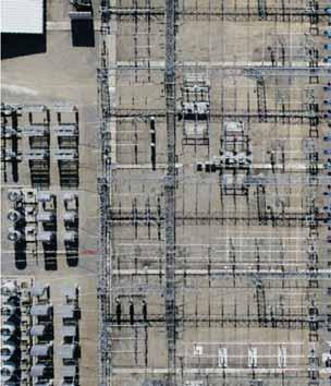
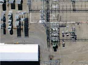
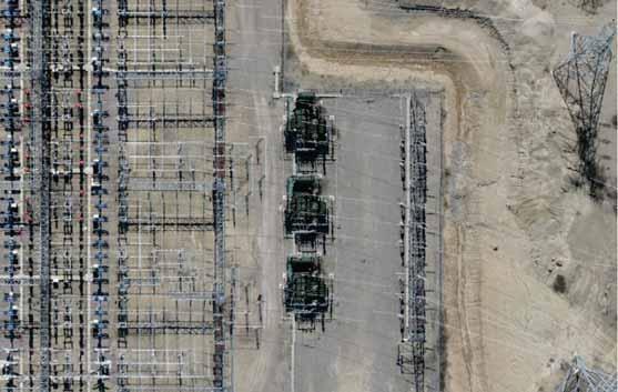
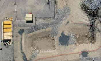


37 Figure 2-14: Existing Radisson Converter Station: Proposed Work Areas
38
39 KR3) from the Keeyask Switching Station. KR2 and KR3 will enter the west side of the station utilizing dead-ended steel structure with line switches. KR2 and KR3 lines will proceed to underground around the station and finally terminate to Bay 1. This is done to avoid complex line crossings into the station. Thirty one 138 kv ac breakers will also need to be replaced due to fault levels exceeding existing breaker ratings kv ac Switchyard Components within the 138 kv ac switchyard will include all the necessary concrete foundations, steel structures and equipment supports, and station service transformers. Equipment foundations will range from concrete slab-on-grade to deep-piled foundations, depending on equipment weight and geotechnical conditions. Steel structures will be placed on the foundations and will support electrical apparatus and electrical conductors, and hardware associated with the switchyard and transformer functions. Detailed numbers and ratings of the switchyard electrical apparatus to be located within the ac switchyard will not be known until final design is complete kv ac Circuit Breakers and Disconnect Switches The design and structure of circuit breakers and disconnect switches for the Radisson Converter Station is comparable to those intended for the Keeyask Switching Station. Thirty-six three-phase 138 kv circuit breakers will be required for the Radisson ac switchyard. Each breaker will contain approximately 75 kg of insulating gas, comprised of approximately 50% SF 6 and 50% CF 4 or N Station Grounding The current Radisson Converter Station includes installation of a station ground grid throughout most of the larger station area. The grid comprises numerous copper clad steel ground rods (approximately three metres in length) driven into the ground, connected together below the insulating stone surface with bare copper wire, and also connected to metallic objects such as steel structures, equipment structures and foundations, transformers, buildings, pipes, cables, etc. The Keeyask Transmission Project will require extension of the ground grid to the 138 kv ac switchyard areas. The ground grid is required for personnel and equipment safety, and will conform to Manitoba Hydro best practices for station design. The extension will be integrated with and, where necessary, will supplement the existing ground grid network. KEEYASK TRANSMISSION PROJECT EA REPORT CHAPTER 2 PROJECT DESCRIPTION 2-13
40 Communications Facilities The Radisson Converter Station has existing communication infrastructure at the site. This infrastructure facilitates reliable integration of the Radisson Converter Station into the existing Manitoba Hydro Communication System, and is generally comprised of fibre optic networks. Optical ground wire, as described in Section , will provide the primary communication pathway to Keeyask Switching Station for control and operation of the Generation Outlet Transmission system Oil Containment The current Radisson Converter Station includes all principal components of the station oil containment system. These include a combination of point-source containment and non-pointsource containment for oil-filled equipment, all in conformance with applicable oil containment standards. Additional primary containment will be required for large Keeyask Transmission Project equipment located within the expanded 138 kv ac switchyard. Primary containment at the equipment location will be provided for equipment containing greater than 5,000 litres of oil. This containment will utilize a concrete, clay or synthetic membrane barrier, extending a minimum of 1.5 m beyond the edge of any the equipment. The majority of the primary containment facilities will be connected to the oil-water separator building using fast drain piping. The extended oil containment facilities will also collect rain, snow melt and water for the fire suppression systems. Water collected in the oil containment system from these sources will undergo oil/water separation in the separator building. 2.4 LAND REQUIREMENTS FOR PROJECT Manitoba Hydro determines the widths of its rights-of-way to allow for safe conductor swing out (i.e., to provide sufficient lateral distance to any object located at the edge of the rights-ofway to avoid flashover under windy conditions), to provide sufficient distance between the line and the rights-of-way edge (and between adjacent lines), to avoid damage in the event of a structure failure, to limit radio interference (based on Canadian Standards Association [CSA] standards respecting radio interference), and, in the case of remote rights-of-way, to facilitate helicopter access for line maintenance or repair. The proposed 138 kv transmission lines and stations will traverse provincial Crown land. As Crown land is involved, Manitoba Hydro will secure the necessary station and transmission line rights-of-way through Crown Land Reservations and easement agreements with the Province of Manitoba. KEEYASK TRANSMISSION PROJECT EA REPORT CHAPTER 2 PROJECT DESCRIPTION 2-14
41 2.4.1 Transmission Lines The width of the right-of-way for the Construction Power line will be 60 m. A 265-m width will be required for the four Unit Transmission Lines between the Keeyask Generating Station and the Keeyask Switching Station. A 200-m width will be required for the three Generation Outlet Transmission lines proposed between the Keeyask Switching Station and Radisson Converter Station. The estimated total cleared area required for all Project transmission lines rights-of-way is approximately 744 ha Stations The proposed Keeyask Switching Station will require 13 ha of land for Project development and an adjacent 22 ha of land will be acquired for possible future expansion, for a total site area of 35 ha. The Construction Power Station will require 2.25 ha of land. No additional land is required for the Radisson Station upgrade. 2.5 CONSTRUCTION ACTIVITIES Overall Schedule The overall construction schedule is shown on Figure Construction Power The Construction Power Transmission Line and Construction Power Station are proposed to be in service by May The property acquisition is scheduled to be completed by February 2014, with construction of the Construction Power Station beginning in April 2014, and the Construction Transmission Line beginning October No construction will begin until all regulatory approvals and property reservations are completed. The earliest clearing and construction would start is November 2013; the exact start date is subject to regulatory approval of the Keeyask Generation Project. The Keeyask Construction Power 138 kv Transmission Line and Station is proposed to be in service by July The initial 138 kv Generation Outlet Transmission line (KR1), designed for backup construction power supply from Radisson to the Construction Power Station, is scheduled to be completed by May It is expected due to time and weather constraints that only the right-of-way for KR1 will be cleared at this time and KR2 and KR3 will be cleared prior to 2017 when construction is expected to begin. KEEYASK TRANSMISSION PROJECT EA REPORT CHAPTER 2 PROJECT DESCRIPTION 2-15
Bipole III Transmission Project
 Bipole III Transmission Project Clean Environment Commission Public Hearings Fall 2012 System Planning Ronald Mazur BP III Keewantinoow Limestone Kettle Kelsey Jenpeg Grand Rapids OVERVIEW Transmission
Substation: From the Outside Looking In.
 1 Substation: From the Outside Looking In. Moderator n Ron Spataro AVO Training Institute Marketing Manager 2 Q&A n Send us your questions and comments during the presentation 3 Today s Presenter n Greg
Field Instruction. Induced voltages can occur in overhead lines, underground cables, or in switchyards.
 8.3 Induced Voltage Purpose The purpose of this instruction is to provide awareness of Electrostatic and Electromagnetic induced voltages and the method required to reduce or eliminate it. An induced voltage
TRANSMISSION ASSETS. Filed: September 12, 2006 EB Exhibit D1 Tab 1 Schedule 2 Page 1 of INTRODUCTION
 Filed: September, 00 EB-00-00 Schedule Page of TRANSMISSION ASSETS.0 INTRODUCTION 0 Hydro One Networks Inc. is licensed by the Ontario Energy Board (OEB) to own, operate and maintain transmission facilities
CONTINUING EDUC ATION
 3 CONTINUING EDUC ATION FOR WISCONSIN ELECTRICIANS 2017 NEC Article 250 2 Hours WISCONSIN CONTRACTORS INSTITUTE N16 W23217 Stone Ridge Drive Suite 290 Waukesha, WI 53188 262-409-4282 www.wcitraining.com
Single Line Diagram of Substations
 Single Line Diagram of Substations Substations Electric power is produced at the power generating stations, which are generally located far away from the load centers. High voltage transmission lines are
HVDC High Voltage Direct Current
 HVDC High Voltage Direct Current Typical HVDC Station BACK TO BACK CONVERTER STATION MONO POLAR WITH GROUND RETURN PA Back to Back Converters indicates that the Rectifiers & Inverters are located in the
Unit 2. Single Line Diagram of Substations
 Unit 2 Single Line Diagram of Substations Substations Electric power is produced at the power generating stations, which are generally located far away from the load centers. High voltage transmission
STATE OF NEW JERSEY BOARD OF PUBLIC UTILITIES
 STATE OF NEW JERSEY BOARD OF PUBLIC UTILITIES : IN THE MATTER OF THE PETITION OF : PUBLIC SERVICE ELECTRIC AND GAS : COMPANY FOR A DETERMINATION : PURSUANT TO THE PROVISIONS OF : N.J.S.A. 0:D-1 : BPU DOCKET
Embedded Generation Connection Application Form
 Embedded Generation Connection Application Form This Application Form provides information required for an initial assessment of the Embedded Generation project. All applicable sections must be completed
6B.6 Substation Grounding
 1 No v 1 6 1 No v 1 6 Iu d a Mo r a r a n d ma n a g e r R a c h e le Ha n n o n Vo l.6 -S u b s ta tio n a n d Hig h Vo lta g e E q u ip me n t;p a r tb -S u b s ta tio n Co n fig u r a tio n s 1. Scope
VI 3 - i TABLE OF CONTENTS
 VI 3 - i TABLE OF CONTENTS 3 PROJECT SPECIFIC DATA... 1 3.1 DEFINITIONS... 1 3.1.1 Design Data, High and Medium Voltage... 1 3.1.2 Design Data, Low Voltage Equipment... 2 3.1.3 Phase Relationship... 3
II Design Criteria for Electrical Facilities Connected to the PJM 765 kv, 500 kv, 345 kv, 230 kv, 138 kv, 115 kv, & 69 kv Transmission Systems
 II Design Criteria for Electrical Facilities Connected to the PJM 765 kv, 500 kv, 345 kv, 230 kv, 138 kv, 115 kv, & 69 kv Transmission Systems These design criteria have been established to assure acceptable
Customer Connection Guide Updates Effective May 2017
 This document provides a list of the updates to the EPCOR Distribution and Transmission Inc. (EDTI) Customer Connection Guide. If you have any questions, please contact EDTI Customer Engineering Services
B422 - PRECAST REINFORCED CONCRETE BOX CULVERTS AND BOX SEWERS - OPSS 422
 B422 - PRECAST REINFORCED CONCRETE BOX CULVERTS AND BOX SEWERS - OPSS 422 422.1 GENERAL The work under these tender items consists of the fabrication and installation in open cut of precast reinforced
ENVIRONMENTAL ASSESSMENT (EA) PROCESS
 PROCESS") ENVIRONMENTAL ASSESSMENT (EA) PROCESS THE PROJECT Emera Newfoundland & Labrador (ENL) is seeking environmental regulatory approvals to construct and operate the Maritime Link Transmission Project between
ENVIRONMENTAL ASSESSMENT (EA) PROCESS THE PROJECT Emera Newfoundland & Labrador (ENL) is seeking environmental regulatory approvals to construct and operate the Maritime Link Transmission Project between
3.1 Overview of ATCO Electric s URD System Design
 Page: 3-1 3.0 URD DESIGN GUIDELINES 3.1 Overview of ATCO Electric s URD System Design ATCO Electric s design for distribution power supply to URD areas is a primary looped supply system. This is generically
Central Hudson Gas & Electric Corporation. Transmission Planning Guidelines
 Central Hudson Gas & Electric Corporation Transmission Planning Guidelines Version 4.0 March 16, 2016 Version 3.0 March 16, 2009 Version 2.0 August 01, 1988 Version 1.0 June 26, 1967 Table of Contents
MidAmerican Energy Company 69 kv Facility Ratings Methodology
 MidAmerican Energy Company 69 kv Facility Ratings Methodology Version 1.0 Issued by: Luke Erichsen Reviewed by: Tom Mielnik Last Reviewed: 8/29/2012 1 1.0 Scope: This document provides MidAmerican Energy
Delivering Reliability. Services. Strength You Can Count On. oldcastleprecast.com/services
 Delivering Reliability A Strength You Can Count On SERVICES TENANT IMPROVEMENTS Above And Below Ground Solutions Strength You Can Count On Oldcastle Precast is well trained and knowledgeable in all aspects
Item 550 Chain Link Fence
 Item Chain Link Fence 1. DESCRIPTION 2. MATERIALS Furnish, install, remove, repair, or replace chain link fence and gates. Furnish certification from the chain link fence materials manufacturer stating
MANITOBA HYDRO TRANSMISSION SYSTEM INTERCONNECTION REQUIREMENTS. April 2009 Version 2
 MANITOBA HYDRO TRANSMISSION SYSTEM INTERCONNECTION REQUIREMENTS April 2009 Version 2 LEGISLATIVE AUTHORITY Section 15(5) of The Manitoba Hydro Act authorizes Manitoba Hydro to set, coordinate and enforce
East-South HVDC Interconnector II, India : in commercial operation since 2003
 8006/0 5 HVDC / FACTS Highlights http://www.siemens.com/facts http://www.siemens.com/hvdc NEW! >>> Welcome to Siemens Highlights & Innovations in Transmission and Distribution East-South HVDC Interconnector
Great Northern Transmission Line: Behind the (Electrical) Design
 Design") Great Northern Transmission Line: Behind the (Electrical) Design November 8, 2017 Christian Winter, P.E. Minnesota Power Sivasis Panigrahi, P.E. POWER Engineers, Inc. What is the Great Northern Transmission
Great Northern Transmission Line: Behind the (Electrical) Design November 8, 2017 Christian Winter, P.E. Minnesota Power Sivasis Panigrahi, P.E. POWER Engineers, Inc. What is the Great Northern Transmission
Guidance for UK Fire and Rescue Services. Dealing with incidents on or near National Grid high voltage overhead lines
 Guidance for UK Fire and Rescue Services Dealing with incidents on or near National Grid high voltage overhead lines This document offers guidance to the UK s Fire and Rescue Services for dealing with
MidAmerican Energy Company 100 kv and Above Facility Ratings Methodology
 MidAmerican Energy Company 100 kv and Above Facility Ratings Methodology For NERC Standard FAC-008 and FAC-009 Issued by: Dan Custer Reviewed by: Tom Mielnik Version 2.7 1 1.0 Scope: This document provides
SECTION VI SCOPE OF WORK
 SECTION VI SCOPE OF WORK Overhead Lines and Underground cables VI 5.2 - i TABLE OF CONTENTS 5.2 SCOPE OF WORKS... 1 5.2.1 General... 1 5.2.2 Factory Acceptance Test... 2 5.2.3 33KV Lines and Cables...
INTRODUCTION. General Design Criteria o (include charts from Section 2 of TSS) Functional Criteria o (from TSS section 3) Accessibility and Layout
 Functional Criteria o (from TSS section 3) Accessibility and Layout") Substation Subgroup Members: Please update the sections below you volunteered to review using the track changes option or highlight your changes. Once done, email your updated document to Scott Herb (SEHerb@pplweb.com)
Substation Subgroup Members: Please update the sections below you volunteered to review using the track changes option or highlight your changes. Once done, email your updated document to Scott Herb (SEHerb@pplweb.com)
Article 250 Grounding & Bonding
 Article 250 Grounding & Bonding AMERICAN ELECTRICAL INSTITUTE N16 W23217 Stone Ridge Dr. Waukesha, WI 53188 855-780-5046 www.aeitraining.com DISCLAIMER NOTE: This course is APPROVED for continuing education
Fatima Michael college of Engineering and Technology
 Fatima Michael college of Engineering and Technology DEPARTMENT OF ELECTRICAL AND ELECTRONICS ENGINEERING EE2303 TRANSMISSION AND DISTRIBUTION SEM: V Question bank UNIT I INTRODUCTION 1. What is the electric
B2-301 IMPROVING DOUBLE CIRCUIT TRANSMISSION LINE RELIABILITY THROUGH LIGHTNING DESIGN
 21, rue d'artois, F-7008 Paris http://www.cigre.org B2-301 Session 200 CIGRÉ IMPROVING DOUBLE CIRCUIT TRANSMISSION LINE RELIABILITY THROUGH LIGHTNING DESIGN J. A. (TONY) GILLESPIE & GLENN STAPLETON Powerlink
Remotes Case 2&3 Form REINDEER Cases 2&3 -Connection Impact Assessment (CIA) Application
 Application") General Application Information Remotes Case 2&3 Form REINDEER Cases 2&3 -Connection Impact Assessment (CIA) Application Hydro One Remote Communities Inc. Lori.Rice@hydroone.com 1-807-474-2828 This Application
General Application Information Remotes Case 2&3 Form REINDEER Cases 2&3 -Connection Impact Assessment (CIA) Application Hydro One Remote Communities Inc. Lori.Rice@hydroone.com 1-807-474-2828 This Application
SECTION CHAIN LINK FENCING
 SECTION 32 31 13 CHAIN LINK FENCING PART 1 - GENERAL 1.01 SECTION INCLUDES A. The Work specified in this Section consists of furnishing and installing permanent chain link fences and gates in accordance
FACILITY RATINGS METHOD TABLE OF CONTENTS
 FACILITY RATINGS METHOD TABLE OF CONTENTS 1.0 PURPOSE... 2 2.0 SCOPE... 3 3.0 COMPLIANCE... 4 4.0 DEFINITIONS... 5 5.0 RESPONSIBILITIES... 7 6.0 PROCEDURE... 8 6.4 Generating Equipment Ratings... 9 6.5
SECTION CHAIN LINK FENCING AND GATES AND SOFTBALL BACKSTOP
 1 1 1 0 1 0 1 0 1 SECTION 1 1 CHAIN LINK FENCING AND GATES AND SOFTBALL BACKSTOP BASED ON DFD MASTER SPECIFICATION DATED /01/ P A R T 1 - G E N E R A L SCOPE The work under this section shall consist of
Standard Prices for Generators 2010
 Standard Prices for Generators 2010 Distribution System Operator ESB Networks Page 1 of 13 CONTENTS 1.0 Background...3 2.0 Standard Pricing Approach...3 Schedule of Charges for generators excluding VAT...6
City of Regina Standard Construction Specification SECTION 2660 CHAIN LINK FENCE
 1.0 GENERAL 1.1 Scope 1.1.1 The work shall consist of supply and installing chain link fence, including braces and gates, as shown on the plans and specifications at the locations designated by the Engineer.
Shunt Reactors. Global Top Energy, Machinery & Plant Solution Provider
 Shunt Reactors Global Top Energy, Machinery & Plant Solution Provider Our Business Brief introduction of Hyosung Power & Industrial Systems PG While Hyosung is an established name for world-class electrical
DUKE ENERGY CAROLINAS TRANSMISSION SYSTEM PLANNING GUIDELINES. Transmission Planning
 DUKE ENERGY CAROLINAS TRANSMISSION SYSTEM PLANNING GUIDELINES Transmission Planning TABLE OF CONTENTS I. SCOPE 1 II. TRANSMISSION PLANNING OBJECTIVES 2 III. PLANNING ASSUMPTIONS 3 A. Load Levels 3 B. Generation
Welcome to the Session on. HT Distribution Network
 Welcome to the Session on HT Distribution Network Learning Objective By the end of this session you will be able to: Explain the HT distribution network breakdown maintenance - possible faults, identification
SHADOWBOX INSTALLATION FOR: Standard 6 H x 8 W Shadowbox Fence 5 x 5 Routed Posts Dog Ear or Straight-Edge Pickets 1.75 x 3.5 Rail
 SHADOWBOX INSTALLATION FOR: Standard 6 H x 8 W Shadowbox Fence 5 x 5 Routed Posts Dog Ear or Straight-Edge Pickets 1.75 x 3.5 Rail Storage and Handling Fence Preparation and Layout Locate and Set Posts
Embedded Generation Connection Application Form
 Embedded Generation Connection Application Form This Application Form provides information required for an initial assessment of the Embedded Generation project. All applicable sections must be completed
T E C H N I C A L M E M O R A N D U M. ON PARTICULAR ASPECTS RELATED 400 kv TRANSMISSION
 T E C H N I C A L M E M O R A N D U M ON PARTICULAR ASPECTS RELATED 400 kv TRANSMISSION Prepared by Prepared for : Dr Pieter H Pretorius, Trans-Africa Projects : Mr Henry Nawa, Senior Environmental Advisor,
American Electrical Institute
 American Electrical Institute Oregon Electricians Continuing Education Grounding & Bonding (Article 250) 4 Hours American Electrical Institute PO Box 31131 Spokane, WA 99223 www.aeitraining.com Article
Electrical Power Systems
 Electrical Power Systems CONCEPT, THEORY AND PRACTICE SECOND EDITION SUBIR RAY Professor MVJ College of Engineering Bangalore PHI Learning Pfcte tofm Delhi-110092 2014 Preface xv Preface to the First Edition
CONDITIONS FOR A TENTATIVE APROVAL FOR CONNECTION OF TRANSFORMERS
 CONDITIONS FOR A TENTATIVE APROVAL FOR CONNECTION OF TRANSFORMERS Management has tentatively approved your request subject to the following conditions: 1. All distribution materials/equipment must be purchased
SRA 2250/6 RESISTOR ARS-01 RESISTOR AUTOMATICS
 ELECTRICAL ENGINEERING DIVISION Distribution Network Department SRA 2250/6 RESISTOR ARS-01 RESISTOR AUTOMATICS ELA T150.2 en SRA 2250/6 Resistor specification The SRA 2250/6 Resistor is intended to increase
University of Central Florida Main Campus. Electric. Service and Meter Installations Requirements. Issued January 26 th, 2017.
 University of Central Florida Main Campus Electric Service and Meter Installations Requirements Issued January 26 th, 2017 1 P a g e Table of Contents 1. GENERAL INFORMATION... 3 2. DEFINITIONS... 3 3.
Customer Requirements RF Antenna Installations
 Application Terms Attachment requirements and clearances on the Pole for Radio Frequency (RF) antenna equipment installations. This standard is intended to allow electrical workers to perform their normal
B4-203 NELSON RIVER POLE 2 MERCURY ARC VALVE REPLACEMENT
 21, rue d'artois, F-75008 Paris http://www.cigre.org B4-203 Session 2004 CIGRÉ NELSON RIVER POLE 2 MERCURY ARC VALVE REPLACEMENT Narinder S. Dhaliwal *, Rick Valiquette, Manitoba Hydro, Winnipeg, Canada
EDS LV SUPPLIES TO MOBILE PHONE BASE STATIONS MOUNTED ON TRANSMISSION TOWERS
 ENGINEERING DESIGN STANDARD EDS 08-2109 LV SUPPLIES TO MOBILE PHONE BASE STATIONS MOUNTED ON TRANSMISSION TOWERS Network(s): Summary: EPN, LPN, SPN This standard provides guidance on the installation of
Busbar and Modular Wiring Systems
 Chapter 11 Busbar and Modular Wiring Systems 11.1 BUSBAR SYSTEM The wide range of busbar system is available and can be used for single or three-phase distribution to many types of applications ranging
Optical Ground Wires (OPGW)
") Optical Ground Wires (OPGW) Presented by NSW (Norddeutsche Seekabelwerke GmbH) 4-Nov-13 / 1 NSW The Company Plant Overview 4-Nov-13 / 2 NSW Ground Wire History Our Experience Ground Wire Cables production
Optical Ground Wires (OPGW) Presented by NSW (Norddeutsche Seekabelwerke GmbH) 4-Nov-13 / 1 NSW The Company Plant Overview 4-Nov-13 / 2 NSW Ground Wire History Our Experience Ground Wire Cables production
Reference Number PDS 04 (RIC Standard: EP SP)
") Discipline Engineering Standard NSW Category Electrical Title Reference Number PDS 04 (RIC Standard: EP 12 10 00 10 SP) Document Control Status Date Prepared Reviewed Endorsed Approved Mar 05 Standards
Discipline Engineering Standard NSW Category Electrical Title Reference Number PDS 04 (RIC Standard: EP 12 10 00 10 SP) Document Control Status Date Prepared Reviewed Endorsed Approved Mar 05 Standards
PRIVACY INSTALLATION FOR: Standard 6 H x 8 W Privacy Fence 4 x 4 Post Sleeve & Brackets Dog Ear or Straight-Edge Pickets 1.75 x 3.
 PRIVACY INSTALLATION FOR: Standard 6 H x 8 W Privacy Fence 4 x 4 Post Sleeve & Brackets Dog Ear or Straight-Edge Pickets 1.75 x 3.5 Rail Storage and Handling Fence Preparation and Layout Locate and Set
POWER FACTOR CORRECTION. HARMONIC FILTERING. MEDIUM AND HIGH VOLTAGE SOLUTIONS.
 POWER FACTOR CORRECTION. HARMONIC FILTERING. MEDIUM AND HIGH VOLTAGE SOLUTIONS. This document may be subject to changes. Contact ARTECHE to confirm the characteristics and availability of the products
UNIVERSITY OF CAMBRIDGE INTERNATIONAL EXAMINATIONS Cambridge International Level 3 Pre-U Certificate Principal Subject
 UNIVERSITY OF CAMBRIDGE INTERNATIONAL EXAMINATIONS Cambridge International Level 3 Pre-U Certificate Principal Subject www.xtremepapers.com PHYSICS 9792/02 Paper 2 Part A Written Paper May/June 2011 PRE-RELEASED
Installation Guide. Capped Cellular PVC Fencing. Table of Contents. Storage and Handling Tools Needed Fence Layout and Locating Posts
 Capped Cellular PVC Fencing Installation Guide Table of Contents Storage and Handling Tools Needed Fence Layout and Locating Posts Installation instructions 4 x 4 Over Sleeve Post - 3.5 Rail Privacy Shadowbox
Embedded Generation Connection Application Form
 Embedded Generation Connection Application Form This Application Form provides information required for an initial assessment of the Embedded Generation project. All applicable sections must be completed
SECTION LOW-VOLTAGE ELECT. DIST. DESIGN AND CONSTRUCTION STANDARDS _ February 2015 PART I: GENERAL
 PART I: GENERAL 1.01 Wiring Devices A. This section of the standard includes design requirements for wiring connections, including receptacles and switches to equipment specified in other sections. a.
RADIO AND TELEVISION TOWER & EQUIPMENT PROPERTY DAMAGE APPLICATION
 RADIO AND TELEVISION TOWER & EQUIPMENT PROPERTY DAMAGE APPLICATION Date of Report: Reported By: Office: Frequency: Address: 1. Broadcasting Co. Principal Mailing Address: Call Letters: Tower Location:
Southern Company Interconnection Requirements for Inverter-Based Generation
 Southern Company Interconnection Requirements for Inverter-Based Generation September 19, 2016 Page 1 of 16 All inverter-based generation connected to Southern Companies transmission system (Point of Interconnection
AC Voltage- Pipeline Safety and Corrosion MEA 2015
 AC Voltage- Pipeline Safety and Corrosion MEA 2015 WHAT ARE THE CONCERNS ASSOCIATED WITH AC VOLTAGES ON PIPELINES? AC concerns Induced AC Faults Lightning Capacitive coupling Safety Code Induced AC Corrosion
ADDENDUM. (1) Ref. Regulation 33.4 (Page 643): (2) Ref. Regulation 71.2 (Page 676): Annexed as Appendix II to these Regulations at page 697.
 Ref. Regulation 33.4 (Page 643): (2) Ref. Regulation 71.2 (Page 676): Annexed as Appendix II to these Regulations at page 697.") ADDENDUM No. AERC. 396/2012/Pt.-III/4.-Assam Electricity Regulatory commission (Terms and Conditions for determination of Multi Year tariff) Regulations, 2015 issued vide notification No. AERC.396/2012/Pt/-II/13
ADDENDUM No. AERC. 396/2012/Pt.-III/4.-Assam Electricity Regulatory commission (Terms and Conditions for determination of Multi Year tariff) Regulations, 2015 issued vide notification No. AERC.396/2012/Pt/-II/13
Kansas City Power & Light Company. Transmission Facility Rating Methodology
 Company Prepared by: KCP&L Transmission Planning December 6, 2017 Table of Contents 1. Purpose...4 2. Generator Rating Methodology...4 3....4 3.1. Equipment Rating Methodology...4 3.2. Items considered
SECTION VI SCOPE OF WORK
 SECTION VI SCOPE OF WORK Overhead Lines and Underground cables VI 5.2 - i TABLE OF CONTENTS 5.2 SCOPE OF WORKS... 1 5.2.1 General... 1 5.2.2 Factory Acceptance Test... 2 5.2.3 33KV Lines and Cables...
TRANSMISSION ENGINEERING STANDARD TES-P , Rev. 0 TABLE OF CONTENTS 1.0 SCOPE 2.0 BONDING METHODS
 1.0 SCOPE 2.0 BONDING METHODS 2.1 Introduction 2.2 Design 2.3 Single-Point Bonding 2.4 Cross Bonding 2.5 Sheath Sectionalizing Joints 2.6 Sheath Standing Voltage 2.7 Sheath Voltage at Through Fault 2.8
ISO Rules Part 500 Facilities Division 502 Technical Requirements Section SCADA Technical and Operating Requirements
 Section 502.8 SCADA Technical and Operating Applicability 1 Section 502.8 applies to: (a) the legal owner of a generating unit: (i) connected to the transmission facilities in the balancing authority area
Proposed Action Hutch Mountain Communications Site Coconino National Forest June 2016
 Proposed Action Hutch Mountain Communications Site Coconino National Forest June 2016 PURPOSE AND NEED The proposed Hutch Mountain Communications Site project is part of a broader wireless industry strategy
Neutral Earthing. For permanent or temporary neutral earthing in HV systems
 Neutral Earthing Resistors RESISTORS For permanent or temporary neutral earthing in HV systems For continuous or temporary low-resistance neutral grounding in medium voltage systems Neutral point connection
RADIO AND TELEVISION TOWER & EQUIPMENT PROPERTY DAMAGE APPLICATION
 Hull & Company Dallas P: (972) 789-1962 F: (972) 789-1967 Houston P: (281) 759-4855 F: (281) 759-7245 hullandco-texas.com RADIO AND TELEVISION TOWER & EQUIPMENT PROPERTY DAMAGE APPLICATION The following
ESB National Grid Transmission Planning Criteria
 ESB National Grid Transmission Planning Criteria 1 General Principles 1.1 Objective The specific function of transmission planning is to ensure the co-ordinated development of a reliable, efficient, and
2/15/2015. Current will always try to return to its source. In order for there to be current, there must be a complete circuit
 Current will always try to return to its source In order for there to be current, there must be a complete circuit Current will take as many paths or circuits available to it to return to the source The
COUNTY OF CLEVELAND, NORTH CAROLINA AGENDA FOR THE PLANNING BOARD MEETING. July 31, :00 PM. Commissioners Chamber
 COUNTY OF CLEVELAND, NORTH CAROLINA AGENDA FOR THE PLANNING BOARD MEETING July 31, 2018 6:00 PM Commissioners Chamber Call to order and Establishment of a Quorum Invocation and Pledge of Allegiance Approval
PART MATERIALS. Section Fencing Materials. Description
 PART 03000 - MATERIALS Section 03010 - Fencing Materials Description 03010.00 Scope - This section consists of the test requirements, specifications and tolerances for barbed wire, woven wire and chain
Installation Instructions. Tools Needed. Tape measure. Level. Shovel or Post hole digger. Concrete. Drill. Stakes. Mallet or hammer.
 Installation Guide EcoStone Fence 1330 West 400 North Orem, UT 84057 Toll Free 1.866.648.9336 Tel. 1.801.655.5236 Fax 1.801.655.5240 www.ecostonefence.com Installation Instructions Introduction. These
Basic Principles and Operation of Transformer
 Basic Principles and Operation of Transformer CONSTRUCTIONAL ASPECTS Cores In order to enhance core s magnetic properties, it is constructed from an iron and silicon mixture (alloy). The magnetic core
SECTION 5 TRANSFORMERS
 SECTION 5 TRANSFORMERS Necessary transformers will be installed and maintained by The City of Aspen. The City of Aspen will not furnish transformers unless they are of standard size and voltage as established
State College Area School District
 State College Area School District The following is a guideline for project design submittals to the Facility Committee of the State College Area School District. During the design process the committee
Functional Specification Revision History
 Functional Specification Revision History Revision Description of Revision By Date V1D1 For Comments Yaoyu Huang October 27, 2016 V1 For Issuance Yaoyu Huang November 21, 2016 Section 5.3 updated Transformer
Appendix S: PROTECTION ALTERNATIVES FOR VARIOUS GENERATOR CONFIGURATIONS
 Appendix S: PROTECTION ALTERNATIVES FOR VARIOUS GENERATOR CONFIGURATIONS S1. Standard Interconnection Methods with Typical Circuit Configuration for Single or Multiple Units Note: The protection requirements
MV ELECTRICAL TRANSMISSION DESIGN AND CONSTRUCTION STANDARD. PART 1: GENERAL 1.01 Transformer
 PART 1: GENERAL 1.01 Transformer A. This section includes liquid filled, pad mounted distribution transformers with primary voltage of 12kV or 4.16kV (The University will determine primary voltage), with
Geoff Brown & Associates Ltd
 Geoff Brown & Associates Ltd REVIEW OF WESTERN POWER S APPLICATION FOR A TECHNICAL RULES EXEMPTION FOR NEWMONT MINING SERVICES Prepared for ECONOMIC REGULATION AUTHORITY Final 20 August 2015 Report prepared
A REPORT TO THE BOARD OF COMMISSIONERS OF PUBLIC UTILITIES. Electrical - NA. Protection & Control - NA. \\Q 30 JuLy Transmission & Distribution - NA
 A REPORT TO THE BOARD OF COMMISSIONERS OF PUBLIC UTILITIES Electrical - NA Protection & Control - NA \\Q 30 JuLy Transmission & Distribution - NA Telecontrol System Planning - NA Replace MDR-4000 Microwave
Utility System Lightning Protection
 Utility System Lightning Protection Many power quality problems stem from lightning. Not only can the high-voltage impulses damage load equipment, but the temporary fault that follows a lightning strike
Need for grounding Codes and Standards for grounding Wind Turbine Generator grounding design Foundation + Horizontal Electrode grounding design
 IEEE PES Transmission and Distribution Conference 2008 Panel Session Large Wind Plant Collector Design Wind Farm Collector System Grounding by Steven W. Saylors, P.E. Chief Electrical Engineer Vestas Americas
EH27401 Communication and Control in Electric Power Systems Lecture 2. Lars Nordström
 EH27401 Communication and Control in Electric Power Systems Lecture 2 Lars Nordström larsn@ics.kth.se 1 Course map 2 Outline 1. Power System Topologies Transmission Grids vs Distribution grids Radial grids
Amtrak s 138 kv Transmission System that supplies traction power to electric locomotives traveling on the
 Word Count: 3039 Replacement of Amtrak s 138 KV Cable through the Baltimore Tunnels Raymond G. Verrelle, PE Amtrak Engineering Department 30 th St. Station, 4 th Floor South Fourth Floor, South Tower Philadelphia,
Wisconsin Contractors Institute Continuing Education
 IMPORTANT NOTE: You should have received an email from us with a link and password to take your final exam online. Please check your email for this link. Be sure to check your spam folder as well. If you
SE Region Asset Specifications Four Strand Barbed Wire Fence Specifications
 Lands Division Sustainable Resource Development SE Region Asset Specifications Four Strand Barbed Wire Fence Specifications 1. Project Materials The contractor is to supply all the labour, tools and equipment
ORKNEY CAITHNESS CONNECTION
 Helping to secure a Renewable Future: Orkney Caithness Connection - 132kV Scottish Hydro Electric Transmission Limited Scottish Hydro Electric Transmission Limited (SHETL) is part of SSE plc and is the
Rattling Brook Hydro Plant Refurbishment. Table of Contents. 1.0 Introduction Background Electrical Works...7
 Table of Contents Page 1.0 Introduction...1 2.0 Background...2 3.0 Civil Works...3 3.1 Penstock...3 3.1.1 Optimum Penstock Diameter...4 3.1.2 Penstock Replacement Options...4 3.2 Surge Tank...5 3.3 Civil
Distribution/Substation Transformer
 Distribution/Substation Transformer Type VFI, Vacuum Fault Interrupter Transformer Option Functional Specification Guide Functional specification for 15 kv, 25 kv, or 35 kv vacuum fault interrupter distribution/substation
CHAPTER 15 GROUNDING REQUIREMENTS FOR ELECTRICAL EQUIPMENT
 CHAPTER 15 GROUNDING REQUIREMENTS FOR ELECTRICAL EQUIPMENT A. General In a hazardous location grounding of an electrical power system and bonding of enclosures of circuits and electrical equipment in the
SAFETY ISSUES RELATED TO THE CONNECTION OF MV AND HV GROUNDING
 SAFETY ISSUES RELATED TO THE CONNECTION OF MV AND HV GROUNDING Y. Rajotte J. Fortin G. Lessard Hydro-Québec, Canada Hydro-Québec, Canada Hydro-Québec, Canada e-mails: rajotte.yves@ireq.ca fortin.jacques@ireq.ca
PRACTICAL PROBLEMS WITH SUBSTATION EARTHING
 1 PRACTICAL PROBLEMS WITH SUBSTATION EARTHING Dr Hendri Geldenhuys Craig Clark Eskom Distribution Technology This paper considers the issues around substation sites where the soil resistivity is of particularly
ATTACHMENT - AESO FUNCTIONAL SPECIFICATION
 ATTACHMENT - AESO FUNCTIONAL SPECIFICATION Functional Specification Revision History Revision Description of Revision By Date D1 For internal Comments Yaoyu Huang January 8, 2018 D2 For external Comments
CONTENTS. 1. Introduction Generating Stations 9 40
 CONTENTS 1. Introduction 1 8 Importance of Electrical Energy Generation of Electrical Energy Sources of Energy Comparison of Energy Sources Units of Energy Relationship among Energy Units Efficiency Calorific
Design, Control and Application of Modular Multilevel Converters for HVDC Transmission Systems by Kamran Sharifabadi, Lennart Harnefors, Hans-Peter
 1 Design, Control and Application of Modular Multilevel Converters for HVDC Transmission Systems by Kamran Sharifabadi, Lennart Harnefors, Hans-Peter Nee, Staffan Norrga, Remus Teodorescu ISBN-10: 1118851560
TRANSMISSION AND SUBSTATION PROJECT S EJO # GS0021
 TRANSMISSION AND SUBSTATION PROJECT S OPERATING COMPANY: EGSI-TX CUSTOMER: COTTONWOOD ENERGY COMPANY, LP EJO # GS0021 FACILITY STUDY OPTIONAL SYSTEM UPGRADES FOR 1240 MW, IPP PROJECT NEAR HARTBURG, TX