EVOLUTION. Variable Character Ladder Filter. Operation Manual. Copyright 2016 Rossum Electro-Music LLC
|
|
|
- Margery Simpson
- 6 years ago
- Views:
Transcription
1 EVOLUTION Variable Character Ladder Filter Operation Manual Copyright 2016 Rossum Electro-Music LLC
2 Contents 1. Introduction 3 2. Module Installation 4 3. Overview 6 4. Input and Output 7 5. Frequency Control 8 6. Q Control Genus Control Species Control Specifications From Dave s Lab: The Evolution of EVOLUTION Acknowledgements 19 2
3 1. Introduction Thanks for purchasing (or otherwise acquiring) the Rossum Electro-Music Evolution Variable Character Ladder Filter. This manual will give you the information you need to get the most out of Evolution. However, the manual assumes you already have a basic understanding of synthesis and synthesizers. If you re just starting out, there are a number of good reference and tutorial resources available to get you up to speed. One that we highly recommend is: Power Tools for Synthesizer Programming (2nd Edition) By Jim Aikin Published by Hal Leonard HL Additionally, for the technically and/or historically minded among you, check out Section 10, The Evolution of EVOLUTION, for Dave s account of how Evolution came to be. Support In the unlikely event that you have a problem with your Evolution, tell us about it here: support-request-form/ and we ll get you sorted out. If you have any questions, comments, or just want to say Hi!, you can always get in touch here: and we ll get back to you. Happy music making! 3

4 2. Installation As you will have no doubt noticed, the rear of Evolution is a circuit board with exposed parts and connections. When handling Evolution, it s best that you hold it by the edges of the front panel or circuit board. It s not particularly easy to blow up, but why take chances? More specifically, the biggest risk (to the extent that there s a risk), is damage by static electricity. Particularly on dry, cold days (or if you ve just shuffled across your shag carpet in fuzzy slippers), make a point of touching the metal panel first, before touching any other part of the module. While all Rossum Electro-Music modules are protected against reverse polarity damage, both to your module and your system, care should still be taken to connect the power cable correctly. (For more detail on our unique protection method, check out Dave s discussion of Circuit Protection in Section 10.) Plug the included 16-pin connector into the header on the rear of the module such that the red stripe on the cable (the -12V side) is on the same end of the header as the Red Stripe `-12V text on the PCB. Evolution requires, at most, 85mA of +12V and 75mA of -12V. We have included both M3 and M2.5 (for vector rails) mounting screws. Use what fits your system. If rack rash is of concern to you, use the included nylon washers when mounting Evolution in your case. 4
5 5
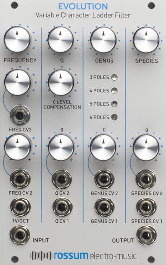
6 3. Overview Evolution is a pure analog lowpass filter that offers in a single module the characteristics of a wide variety of synthesizer filter types. At the core of Evolution is Dave s unique implementation of Bob Moog s iconic ladder filter from the original E-mu Systems 2100 LPF module (which, incidentally, Dave counts as his favorite sounding of all of the filters he designed). Check Section 10 to learn what made the 2100 (and, consequently, Evolution) so special. For Evolution, Dave has designed new capabilities that not only allow you to dial in all of the outstanding qualities of the original 2100, but combine to let you create the sonic characters of other synth filters that are not otherwise possible with traditional ladder filters. They include: > A Genus control that allows voltage control of the number of filter poles, allowing a range of entirely new and striking audio effects. > A Species control that allows voltage control of the signal level into the ladder, letting you control the intensity of the filter s characteristic distortion. > Voltage controlled resonance with a variable Q Level Compensation control that lets you control the balance of the resonant signal and the frequencies below the cutoff frequency (which would otherwise be attenuated as the resonance is increased). > An extremely accurate and temperature stable frequency control exponential generator, rivaling the specifications of the best analog VCOs Taken together, Evolution gives you everything from the platonic ideal of the pure classic ladder filter to an almost unlimited selection of alternative filter characteristics. In the following sections, we ll look at each of Evolution s functions in turn. 6
7 4. Input and Output The Input and Output jacks let you get audio into and out of Evolution. Evolution is DC coupled throughout, so you can use Evolution to process CVs as well as audio. The Input expects a signal level up to 20Vp-p Depending on the Input level and the settings of the various controls, the Output provides a signal level of up to 20Vp-p without clipping. 7
8 5. Frequency Evolution s Frequency section provides manual and CV control of Evolution s cutoff frequency (i.e., the frequency above which the amplitude of the signal is attenuated). FREQUENCY Knob The FREQUENCY knob allows you to set Evolution s initial cutoff frequency (I.e., the cutoff frequency when no CVs are present). The actual cutoff frequency is controlled by the sum of this knob and all present control voltages. Without CVs present, the range of the control is from approximately 22Hz to 22kHz. With CVs, the available range is from.02hz to 40kHz. When Evolution is in self-oscillation mode (see the Q section below), this control sets the initial frequency of oscillation. NOTE: Refer to the Genus section below to understand how the Poles setting affects the oscillation and resonant frequencies. 1V/OCT CV Input The 1V/OCT CV Input is a calibrated full level control voltage input that is summed with the value of the FREQUENCY knob and the FREQ CV2 and FREQ CV3 inputs. When properly calibrated (as it will be when delivered), Evolution s 1V/Octave tracking is accurate over a 10 octave range (better than many Eurorack VCO modules). When in self-oscillation mode, Evolution serves as an extremely high quality sine wave oscillator. FREQ CV2 Input The FREQ CV2 Input is a control voltage input that is modified by its associated attenuverter and then summed with the value of the FREQUENCY knob and the FREQ CV3 and 1V/OCT inputs. When the attenuverter knob is set to its 0 position, no control voltage is passed to the filter. As the knob is turned clockwise from 0, the amplitude of the control voltage increases until, at maximum clockwise rotation, the full amplitude of the signal at the FREQ CV2 Input is passed through and results in a nominal 1V/Oct response. As the knob is turned counter-clockwise from 0, the signal at the FREQ CV2 Input is inverted (e.g., a CV of +2.5V becomes -2.5V). The farther counterclockwise the knob is turned, the less the attenuation of the inverted signal, until, at maximum counter-clockwise rotation, the full amplitude of the inverse of the signal at the FREQ CV2 Input is passed through, also at a nominal 1V/Oct response. 8
9 FREQ CV3 Input The FREQ CV3 Input is a control voltage input that is modified by its associated conventional attenuator and then summed with the value of the FREQUENCY knob and the FREQ CV2 and 1V/OCT inputs. When the attenuator knob is set to its maximum counter-clockwise position, no control voltage is passed to the filter. As the knob is turned clockwise, the amplitude of the control voltage increases until, at maximum clockwise rotation, the full amplitude of the signal at the FREQ CV3 Input is passed through at a nominal 1V/Oct response. 9
10 6. Q (Resonance) 10 Evolution s Q section provides manual and CV control of the height of the resonant peak at (or near) Evolution s cutoff frequency, as well as the level of the frequencies below the resonant peak. (See the discussion of the effect of the Genus setting on the frequency of the resonant peak below.) Q Knob The Q knob allows you to set the initial height of Evolution s resonant peak (I.e. the height of the peak when no CVs are present). The actual height of the resonant peak is controlled by the sum of this knob and all present control voltages. This control produces a voltage range of between 0V and 7V. When the Q knob is turned clockwise to about 4V, the filter will enter self-oscillation mode, producing a pure sine wave. In this mode, Evolution acts as a very high-quality sine wave oscillator. NOTE: The purest sine wave and the most accurate tracking occur when the filter is just barely into oscillation and the Genus control is set to 4 poles. ANOTHER NOTE: Refer to the Genus Section to understand how the Poles setting affects the oscillation and resonant frequencies. YET ANOTHER NOTE: Also refer to the Genus Section to understand how the Q setting affects oscillation during transitions from one pole setting to another. Q LEVEL COMPENSATION In a traditional resonant ladder filter, as the height of the resonant peak is increased, the levels of the frequencies below the resonant peak are attenuated. When the cutoff frequency is swept manually or by a control voltage, the result is the familiar classic wah we re all familiar with. In many cases, that s exactly what you want, as at high Q, you can hear the filter pick out each overtone (or frequency of noise) as you sweep through the audio spectrum. However, if what you want is to add some resonant spice to a pad or fat bass sound, the lower frequency attenuation that results from turning up the Q results in sucking some (or most) of the guts out of the sound, leaving it sounding thin. Luckily, Evolution gives you a choice with the Q LEVEL COMPENSATION control. With the control turned fully counterclockwise, there is no compensation and the filter acts exactly like a traditional ladder filter. As you turn the control clockwise, the amplitudes of the frequencies below the cutoff frequency are progressively boosted until, at full clockwise rotation, they are at their full (pre-attenuation) level. Simply dial in the exact level of compensation you want for each particular patch and you re good.
11 Q CV2 Input The Q CV2 Input is a control voltage input that is modified by its associated attenuverter and then summed with the value of the Q knob and the Q CV1 Input. (If you haven t already read the explanation of how the attenuverters work back up in the FREQ CV2 Input section, you can check that out now.) Q CV1 Input The Q CV1 Input is a full level control voltage input that is summed with the value of the Q knob and the Q CV2 Input. 11
12 7. Genus Evolution s Genus control gives you realtime manual and CV control of the number of poles in the ladder. It is is, as far as we re aware, unique among all implementations of the classic ladder filter. The number of poles defines the slope at which Evolution attenuates frequencies at increasing distance from the cutoff frequency. This parameter is expressed in dbs of attenuation per octave. For example, a lowpass filter with a slope of 24dB per octave (the most common slope of classic Moog-style ladder filters) means that a signal one octave above the cutoff frequency will be attenuated by 24dBs, a signal two octaves above the cutoff frequency will be attenuated by 48dBs, at 3 octaves 72dBs, etc. Expressed as filter poles, each pole provides 6bB of attenuation. The slopes available in Evolution are: 3 poles = 18dB/oct 4 poles = 24dB/oct 5 poles = 30dB/oct 6 poles = 36dB/oct Not only does being able to select the number of poles give Evolution a variety of filter characteristics, the ability to modulate the number of poles in real time (including at audio rates) opens up entirely new sonic vistas. Pole Selection and Resonant and Self-Oscillation Frequencies For technical reasons that you ll find explained in Section 10 (if you re so inclined), different pole selections result in different resonant frequencies relative to the cutoff frequency. The resonant and oscillation frequencies at the various pole settings are: 3 poles: resonant frequency is 10 semitones above the cutoff frequency 4 poles: resonant frequency is equal to the cutoff frequency 5 poles: resonant frequency is 6 semitones below the cutoff frequency 6 poles: resonant frequency is 10.5 semitones below the cutoff frequency Consequently, with Q turned up, modulating the number of poles results in a dynamic shifting of the resonant frequency. This provides unique and striking effects, both at moderate LFO-like rates and at audio frequencies. The same principle governs Evolution s oscillation frequency when in self-oscillation mode. Modulating the Genus parameter while in self-oscillation mode will result in various arpeggiator-like patterns (defined by the amplitude and speed of the modulation). 12
13 GENUS Knob The GENUS knob allows you to set the initial number of poles in the ladder. The actual number of poles is controlled by the sum of this knob and all present control voltages. A swing of 5 volts (either from the Genus knob or via the CV inputs) will cause Evolution to cover the entire range of poles. NOTE: The selection of poles is not a discrete four-step process, but offers a continuous transition between settings (as indicated by the LEDs described next). ANOTHER NOTE: With Q set just at the point of self-oscillation, slowly moving from one pole setting to another will result in Evolution ceasing to oscillate when the setting is between poles (i.e., when two adjacent LEDs are lit). However, with Q set to maximum, oscillation is continuous during transitions between pole settings. If you re modulating Genus during selfoscillation, choose the Q setting that results in whichever of these options you want for your patch. Or modulate Q as well for even more complex effects. GENUS CV2 Input The GENUS CV2 Input is a control voltage input that is modified by its associated attenuverter and then summed with the value of the GENUS knob and the GENUS CV1 Input. (We re pretty sure you know how the attenuverters work by now.) GENUS CV1 Input The GENUS CV1 Input is a full level control voltage input that is summed with the value of the GENUS knob and the GENUS CV2 Input. GENUS LEDs The four LEDs indicate in real time the current number of effective poles as defined by the sum of the GENUS knob and the two CVs. Any time two adjacent LEDs are lit simultaneously, it is an indication that the Genus parameter is between those two pole settings. 13
14 8. Species Evolution s Species section provides manual and CV control of the level of the signal into Evolution s distortion circuitry. As Dave explains it: The ladder design, as I implemented it, has no inherent distortion for signals far below the cutoff frequency. The characteristic timbre of the ladder filter comes primarily from distortions of frequencies near and above the cutoff frequency. The degree of distortion depends on the signal amplitude. Consequently, it is sonically interesting to modulate the signal amplitude going into the ladder, and modulate the output signal with the precise inverse gain. This is the function of the Species control. A high voltage into the Species input will cause the filter to distort more audibly. So, briefly, the Species section gives you control over the ladder s good distortion. NOTE: Because of the way Species is implemented, with Q feedback within the VCAs that control the Species function, Evolution s resonance is unaffected by the Species setting (I.e., the higher the Q setting, the less obvious the Species setting). However, the amplitude of any self-oscillation will be inversely proportional to the Species setting. Consequently, when using the Evolution as an oscillator, the Species control can be used to amplitude modulate the output. If oscillation is combined with an input signal, the results become even more interesting. SPECIES Knob The SPECIES knob allows you to set the initial level of the signal going into the ladder and provides a range of 10 volts. The actual signal level is controlled by the sum of this knob and all present control voltages. With no CVs present, the range of the knob from full counterclockwise up until the 12:00 o clock position results in subtle distortion. The range past the 12:00 o clock position results in more pronounced distortion. SPECIES CV2 Input The SPECIES CV2 Input is a control voltage input that is modified by its associated attenuverter and then summed with the value of the SPECIES knob and the SPECIES CV1 Input. (Attenuverters, blah, blah, blah.) SPECIES CV1 Input The SPECIES CV1 Input is a full level control voltage input that is summed with the value of the SPECIES knob and the SPECIES CV2 Input. 14
15 9. Specifications Controls Initial Frequency Initial Q Q Level Compensation Initial Genus (# of Poles) Initial Species (Distortion Input Level) Signal Input 1x 3.5mm mono socket - 100K Impedance Signal Output 1x 3.5mm mono socket - 1K Impedance Frequency CV Inputs 1x Attenuated - min 50k Impedance 1x w/attenuverter - 100K Impedance 1x 1V/OCT Full Level - 100K Impedance Q CV Inputs 1x Full Level - 100k Impedance 1x w/attenuverter - 100k Impedance Genus CV Inputs 1x Full Level - 100k Impedance 1x w/attenuverter - 100k Impedance Species CV Inputs 1x Full Level - 100k Impedance 1x w/attenuverter - 100k Impedance Power Requirements +/-12V via 16-pin, Doepfer-style connector Current Draw 85mA +12V, 75mA -12V (maximum) Supplied Accessories 1x 16-pin, Doepfer-style cable 4x M3 screws 4x M2.5 screws 4x Nylon washers 1x Quickstart Guide Dimensions 16HP (W); Rear of panel to the top of the power connector: 25 mm (D) 15
16 10. From Dave s Lab: The Evolution of EVOLUTION The fundamental core of the Rossum Electro-Music EVOLUTION Variable Character Filter is Bob Moog s famous ladder filter, which was described in US Patent 3,475,623. This circuit uses the variation of the Bipolar Junction Transistor s emitter resistance with current as the voltage variable element in an RC filter. In the Moog implementation, four identical stages each implemented a single real lowpass pole. The Moog 904A module included a Regeneration control that created a negative feedback path around the four poles. Since each pole provided 45 degrees of phase shift at its -3dB point, increasing this feedback produced a resonant peak at cutoff. The musical utility of the Moog filter is, of course, famous. In 1973, E-mu Systems introduced their 1100 submodule, which was the heart of their 2100 lowpass filter module. The 1100 used a Moog ladder as its core element, but I wanted to isolate the innate audio characteristics of the filter ladder from those colorations resulting from the input levelshifters and output amplifier used in the Moog 904A. I also envisioned a DC-coupled design with a cutoff frequency range well beyond 10 octaves, as well as eliminating variations of the height of the resonant peak or oscillation amplitude with frequency control voltage. I level-shifted the exponential generator to allow the filter signal input to be directly applied to the ladder base. I then designed a completely new output stage for the ladder; this circuit has never (to my knowledge) been used outside my designs. The entire signal path was DC coupled and the resonant feedback path phase compensated. The 1100 was my favorite sounding filter (I liked it more than the SSM2040 I later invented, and kept the 1100 as E-mu s modular lowpass in preference to a cheaper 2040 design). The operational range of the cutoff frequency was from about 0.1Hz to 25kHz, with stable Q s throughout. In launching Rossum Electro-Music, I chose a new implementation of the 1100 filter as the first all-analog module for our Eurorack offering, based on its unique and outstanding audio characteristics. I re-engineered the basic 1100 core using modern available surface-mount components and then added a number of features to the original 1100 design: Ladder filters self-oscillate, and can be used as VCOs. I was able to design the Rossum Electro EVOLUTION s frequency control exponential generator to be extremely accurate and temperature stable, rivaling the specifications of the best analog VCOs. I also added a novel temperature compensation circuit for the ladder emitter resistance. The actual measured specs surprised and delighted me. The resonance ( Q ) of the original 1100 was not voltage controlled. I implemented voltage controlled Q using one cell of an 16
17 SSM2164 VCA. Since the SSM2164 is based on my 1979 design of the SSM2010, this is an apt choice. (Sadly, the original 2164 is no longer produced, so a replica source was needed.) The phase compensation has been maintained, but I added a Q Compensation control. The negative feedback resonance path in the 1100, like the Moog 904A, caused the amplitude of signals in the passband to be attenuated as the Q increased, which some users found undesirable. If instead the signal is inserted into the Q VCA, this effect is eliminated. In EVOLUTION, the Q Compensation control allows insertion of the signal with an arbitrary mix into either of these inputs, allowing the ratio of direct to resonant amplitude to be arbitrarily selected. There is no inherently desirable taper for Q control. In highly resonant, but oscillationproof filters such as state variable designs, it makes sense to exponentially control Q. But in ladder filters, oscillation is expected, and high Q s without oscillation are not practically achievable. The Rossum Electro EVOLUTION implements approximately linear control of the Q VCA. The ladder design, as I implemented it, has no inherent distortion for signals far below the cutoff frequency. The characteristic timbre of the filter comes primarily from distortions of frequencies near and above the cutoff frequency. The degree of distortion depends on the signal amplitude. Consequently, it is sonically interesting to modulate the signal amplitude going into the ladder, and modulate the output signal with the precise inverse gain. This is the function of the Species control. A high voltage into the Species input will go well beyond the linear region of the ladder and cause the filter to distort much more audibly. Because ladder filters produce their resonance by feedback, the relationship of that feedback to the drive VCAs is critical. The Rossum Electro EVOLUTION places the Q feedback within the drive VCAs. This means that the filter s resonance is unaffected by the Species setting, but that the amplitude of any self-oscillation will be inversely proportional to the Species level. When using the filter as an oscillator, the Species control can be used to amplitude modulate the output. If oscillation is combined with an input signal, the results become even more interesting. Like the Q circuit, SSM 2164 cells are used for the drive VCAs. With these additions, the preliminary design of EVOLUTION looked pretty complete. Then Marco asked if it would be possible to add voltage controlled slope (those marketing guys are never satisfied). My first take was that this would not be practical, because varying the slope usually involves controlling complex pole pairs, and the ladder comprises only real poles. 17
18 Then I realized that I could steer the current around individual ladder stages in an analog manner, controlling the number of poles rather than the slope. A prototype proved this was both practical and audibly pleasing. Since the resonant frequency of a ladder filter is determined by the 180 degree phase shift point, it changes with the number of poles: 60 degrees for three poles, 45 for four, 36 for five, and 30 degrees for six poles. Modulating the number of poles produces a unique bubbly sound. Two more tweaks were needed to complete the circuit. Because the number of poles not only affects the phase shift for resonance, it also changes the amount of feedback required for oscillation, the pole control circuit needs to control the Q VCA in a manner such that the same Q control voltage produces the onset of oscillation for each pole setting. And since it s useful but difficult to tune the initial pole setting to be in the center of the range (exactly steering the current to the desired ladder poles), I added analog controlled LEDs to indicate the activation of the poles. We then sent development versions of Evolution to a number of collaborating musicians who responded with some excellent suggestions. These resulted in a few more circuit tweaks to finalize the product. Circuit Protection Eurorack suffers from the problem of power connector reversal. When 10 pin connectors are used, mis-insertion results in a swap of +12V and -12 V, and protection is easily accomplished using various techniques such as series diodes. But more systems are providing the +5V supply and thus use the full 16 pin connector. When this is reversed, a diode-protected module is still safe, but the six connected ground pins in the module will short together the system s +5V and +12V supplies, potentially damaging the power supply and any modules that use +5V. To prevent this, Rossum Electro-Music modules deviate from the standard Eurorack power connector by leaving power connector pins 9 and 10 open, rather than connecting them to ground. When plugged in backwards, this leaves the system +12V supply disconnected. Since ground is still supplied by four pins as well the chassis and any patch cords connected to the module, the dropping of these two pins has no measurable effect on circuit performance, but it means that if a Rossum Electro module is accidentally plugged in backwards, no stress is placed on the +5V supply or modules that use it. 18
19 11. Acknowledgements A number of wonderful people generously provided help, advice, encouragement, and inspiration during the development of Evolution. Many thanks from the Rossum Electro-Music team to: Bob Moog, for his inspiring filter design Jim Aikin Patrick Brede Nancy Enge Josh Holley Mihai Ionescu Kurt Kurasaki Michael Logue William Mathewson Gur Milstein Kevin and Denise Monahan Trish Neilsen David Phipps Bill Putnum Allan Shaffer Dan Snazelle Kirk Southwell Tomio Ueda Andy Zenczak (and the crew at Gadgetbox Studios) And, it goes without saying, but we ll say it anyway, our families for understanding all the late nights and weekends spent not having fun (or doing chores) with them. 19
User Guide V
 XV User Guide V1.10 25-02-2017 Diode Ladder Wave Filter Thank you for purchasing the AJH Synth Sonic XV Eurorack synthesiser module, which like all AJH Synth products, has been designed and handbuilt in
User Guide. Ring Modulator - Dual Sub Bass - Mixer
 sm User Guide Ring Modulator - Dual Sub Bass - Mixer Thank you for purchasing the AJH Synth Ring SM module, which like all AJH Synth Modules, has been designed and handbuilt in the UK from the very highest
Discrete OTA VCF User manual. January 5, 2016 by Rutger Vlek
 Discrete OTA VCF User manual January 5, 2016 by Rutger Vlek Disclaimer When you buy a Eurorack module, you buy a part of a bigger and highly flexible system. River Creative Technology modules have been
// K3020 // Dual VCO. User Manual. Hardware Version E October 26, 2010 Kilpatrick Audio
 // K3020 // Dual VCO Kilpatrick Audio // K3020 // Dual VCO 2p Introduction The K3200 Dual VCO is a state-of-the-art dual analog voltage controlled oscillator that is both musically and technically superb.
FILTER 8 MULTIMODE FILTER/8-PHASE OSCILLATOR CONTENTS INTRODUCTION
 INTRODUCTION Representing the cutting edge in modular analogue voltage controlled filter (VCF) design, Filter 8 offers more possibilities and higher fidelity in 12 HP than ever before. Starting from the
A-108 VCF Introduction. doepfer System A /12/24/48 db Low Pass A-108
 doepfer System A - 100 6/12/24/48 db Low Pass A-108 1. Introduction Level In CV 1 Feedb. BP 6dB A-108 VCF 8 12dB Res. 24dB 48dB Module A-108 is a completely new, unique voltagecontrolled low pass/band
Through-Zero VoltageControlled Oscillator
 Through-Zero VoltageControlled Oscillator Liivatera OÜ Rävala pst. 8, A211 10143 Tallinn Harjumaa Estonia T: +372 637 6441 T: +44 5603 010854 E: contact@liivatera.com Through- Zero VCO Manual 0.1 1 Contents
VCA. Voltage Controlled Amplifier.
 VCA Voltage Controlled Amplifier www.tiptopaudio.com Tiptop Audio VCA User Manual The Tiptop Audio VCA is a single-channel variable-slope voltage-controlled amplifier in Eurorack format. It has the following
Q107/Q107A State Variable Filter
 Apr 28, 2017 The Q107 is dual-wide, full-featured State Variable filter. The Q107A is a single-wide version without the Notch output and input mixer attenuator. These two models share the same circuit
twincussion User Guide
 twincussion User Guide Foreword Analog drum synthesizers are simply unbeatable! No matter how many thousand drum sounds your sample library offers, it will never replace the charm and character of real
MORPHEUS. Stereo Morphing Z-Plane Filter. Operation Manual. v1.5_ Copyright 2017 Rossum Electro-Music LLC
 MORPHEUS Stereo Morphing Z-Plane Filter Operation Manual v1.5_020617 Copyright 2017 Rossum Electro-Music LLC www.rossum-electro.com Contents 1. Introduction 3 2. Module Installation 4 3. Overview 5 4.
A-120 VCF Introduction. doepfer System A VCF 1 A-120
 doepfer System A - 100 VCF 1 A-120 1. Introduction A-120 VCF 1 Module A-120 (VCF 1) is a voltage controlled lowpass filter, which filters out the higher parts of the sound spectrum, and lets lower frequencies
BoomTschak User s Guide
 BoomTschak User s Guide Audio Damage, Inc. 1 November 2016 The information in this document is subject to change without notice and does not represent a commitment on the part of Audio Damage, Inc. No
Mixwitch Mixer & Switcher
 Mixwitch Mixer & Switcher Voltage & clock-controlled analog switch with mixer Introduction Focused versatility seems an oxymoron when describing the features that led us to design the Mixwitch. With only
Z2040. VC-Filter. Tipt p Z2040 LP-VCF GAIN RESONANCE FREQUENCY VC-FM VC-GAIN VC-RES OUT VC-FM. 24db FM. 0db. A u d i o
 Z2040 VC-Filter + VC-GAIN Z2040 LP-VCF GAIN 0db VC-RES MIN CLIP RESONANCE IN MIN MAX FREQUENCY OUT CUT 24db PASS MIN MAX + MIN Tipt p A u d i o MAX Z2040-VC-Filter Design - Gur Milstein Special Thanks
Semi-modular audio controlled analog synthesizer
 Semi-modular audio controlled analog synthesizer Owner s manual 21.7.2017 - Sonicsmith Hello and thank you for purchasing a Squaver P1 synthesizer! The Squaver P1 is a semi-modular, audio controlled, analog
STO Limited Warranty Installation Overview
 v2.5 2 STO Limited Warranty ----------------------------------------------------3 Installation --------------------------------------------------4 Overview --------------------------------------------------------5
BELGRAD. dual peak multimode state variable filter. Model of operator s manual rev. 1976/1.0
 BELGRAD dual peak multimode state variable filter operator s manual rev. 1976/1. Model of 1976 module explained SALUT Thank you for purchasing this Xaoc Devices product. Belgrad is our first all-analog
Galilean Moons. dual amplitude transmutator. USER MANUAL v1.02
 Galilean Moons dual amplitude transmutator USER MANUAL v1.02 Contents Contents... 2 Introduction... 3 Module Features and Specifications... 4 Module Description... 4 Features List... 4 Technical Details...
FXDf Limited Warranty: Installation: Expansion:
 v2.3 1 FXDf Limited Warranty:----------------------------------------2 Installation: --------------------------------------------------3 Expansion: ------------------------------------------------------4
PITTSBURGH MODULAR SYSTEM 10.1 and SYNTHESIZER MANUAL AND PATCH GUIDE
 PITTSBURGH MODULAR SYSTEM 10.1 and 10.1+ SYNTHESIZER MANUAL AND PATCH GUIDE 1 Important Instructions PLEASE READ Read Instructions: Please read the System 10.1 Synthesizer manual completely before use
Polaris Manual v1.00. Polaris. Versatile Multimode VCF / Phaser
 Polaris Manual v1.00 Polaris Versatile Multimode VCF / Phaser Table of Contents Table of Contents Overview Features Installation Before Your Start Installing Your Module Front Panel Controls Inputs & Outputs
AMSynths AM8044 VCF & VCA. Project Notes V2.0
 AMSynths AM8044 VCF & VCA Project Notes V2.0 AMSynths 2013 Rob Keeble Contact: sales@amsynths.co.uk Web Site: www.amsynths.co.uk 18 May 2013 1 Module Description This module is designed around the SSM2044
DOEPFER System A-100 Synthesizer Voice A Introduction. Fig. 1: A sketch
 DOEPFER System A-100 Synthesizer Voice A-111-5 1. Introduction Fig. 1: A-111-5 sketch 1 Synthesizer Voice A-111-5 System A-100 DOEPFER Module A-111-5 is a complete monophonic synthesizer module that includes
DOEPFER System A-100 X-treme Filter A Introduction
 DOEPFER System A-100 X-treme Filter A-106-1 Fig. 1: A-106-1 Controls and In/Outputs 1. Introduction Module A-106-1 is an unique low/high pass filter and has it's origin in our experiments to built a MS20
A-110 VCO. 1. Introduction. doepfer System A VCO A-110. Module A-110 (VCO) is a voltage-controlled oscillator.
 is a voltage-controlled oscillator.") doepfer System A - 100 A-110 1. Introduction SYNC A-110 Module A-110 () is a voltage-controlled oscillator. This s frequency range is about ten octaves. It can produce four waveforms simultaneously: square,
doepfer System A - 100 A-110 1. Introduction SYNC A-110 Module A-110 () is a voltage-controlled oscillator. This s frequency range is about ten octaves. It can produce four waveforms simultaneously: square,
Table of Contents: Limited Warranty:
 v 1.0 2 Table of Contents: ----------------------------------------------------2 Limited Warranty: ----------------------------------------------------3 Installation: ------------------------------------------------------------4
MMG: Limited Warranty: Installation:
 v2.4 2 MMG: Limited Warranty: ----------------------------------------------------3 Installation: ----------------------------------------------------4 Overview:---------------------------------------------------------------5
Q106 Oscillator. Controls and Connectors. Jun 2014
 The Q106 Oscillator is the foundation of any synthesizer providing the basic waveforms used to construct sounds. With a total range of.05hz to 20kHz+, the Q106 operates as a powerful audio oscillator and
Q106A Oscillator. Aug The Q106A Oscillator module is a combination of the Q106 Oscillator and the Q141 Aid module, all on a single panel.
 Aug 2017 The Q106A Oscillator module is a combination of the Q106 Oscillator and the Q141 Aid module, all on a single panel. The Q106A Oscillator is the foundation of any synthesizer providing the basic
pittsburgh modular synthesizers lifeforms sv-1 user manual v.1
 pittsburgh modular synthesizers lifeforms sv-1 user manual v.1 the heart and soul of modular synthesis The Pittsburgh Modular Synthesizers Lifeforms SV-1 is a complete dual oscillator synthesizer, designed
HexVCA Manual v1.0. Front Panel. 1 - VCA Offset CV offset, also referred to as bias knob. CV indicator LED. 2 - IN 1-6 The signal input of the VCAs.
 HexVCA Manual v1.0 The HexVCA contains six separate DC coupled logarithmic VCAs that have their outputs normalled to two outputs. The front panel outputs of each VCA is a switching jack which breaks the
C VCF USER MANUAL
 USER MANUAL The is a four pole low pass filter based in the classical filter SSM2044. This filter chip is responsible for the sound of some well known polysynths from the 80s like the Korg Mono / Poly,
Table of Contents: Limited Warranty:
 v 1.0 2 Table of Contents: ----------------------------------------------------2 Limited Warranty: ----------------------------------------------------3 Installation: -------------------------------------------------------------4
Understanding and using your. moogerfooger. MF-103 Twelve Stage Phaser. MOOG MUSIC, Inc. Asheville, NC USA
 Understanding and using your moogerfooger MF-103 Twelve Stage Phaser MOOG MUSIC, Inc. Asheville, NC USA Welcome to the world of moogerfooger Analog Effects Modules! Your Model MF-103 Twelve-Stage Phaser
A-123 VCF Introduction. doepfer System A VCF 4 A-123
 doepfer System A - 100 VCF 4 A-123 1. Introduction Level Audio In Audio Out A-123 VCF 4 Frequency Resonance Module A-123 (VCF 4) is a voltage-controlled highpass filter, which filters out the lower parts
Limited WARRANTY: Make Noise implies and accepts no responsibility for harm to person or apparatus caused through operation of this product.
 v 1.0 Limited WARRANTY: Make Noise warrants this product to be free of defects in materials or construction for a period of one year from the date of purchase (proof of purchase/invoice required). Malfunction
Analog Synthesizer: Functional Description
 Analog Synthesizer: Functional Description Documentation and Technical Information Nolan Lem (2013) Abstract This analog audio synthesizer consists of a keyboard controller paired with several modules
AMSynths. AM8040 Voltage Controlled Low Pass Filter. Project Notes V2.2
 AMSynths AM8040 Voltage Controlled Low Pass Filter Project Notes V2.2 AMSynths 2013 Rob Keeble Contact: sales@amsynths.co.uk Web Site: www.amsynths.co.uk 29 June 2013 1 Module Description This module is
Manual installation guide v1.2
 Manual installation guide v1.2 Hands up, or we will cross thru zero! I m your Furthrrrr Instant thru-zero linear fm in your Furthrrrr Generator 16-pin DIP IC chip VCO Core replacement that works with any
SSI2144 FATKEYS FOUR-POLE VOLTAGE CONTROLLED FILTER
 SSI FATKEYS FOUR-POLE VOLTAGE CONTROLLED FILTER The SSI reprises the SSM0 of legacy chipmaker Solid State Micro Technology, which many believe to be the best-sounding analog synthesis filter IC ever produced.
Euro Rack Series. Classic VCA. User Manual. Oakley Sound Systems. Discrete Core Voltage Controlled Amplifier V2.3
 Oakley Sound Systems Euro Rack Series Classic VCA Discrete Core Voltage Controlled Amplifier User Manual V2.3 Tony Allgood Oakley Sound Systems CARLISLE United Kingdom Introduction This is the User Manual
Lauren Gresko, Elliott Williams, Elaine McVay Final Project Proposal 9. April Analog Synthesizer. Motivation
 Lauren Gresko, Elliott Williams, Elaine McVay 6.101 Final Project Proposal 9. April 2014 Motivation Analog Synthesizer From the birth of popular music, with the invention of the phonograph, to the increased
ALM473 DUAL MONO \ STEREO AUDIO LEVEL MASTER OPERATION MANUAL IB
 ALM473 DUAL MONO \ STEREO AUDIO LEVEL MASTER OPERATION MANUAL IB6408-01 TABLE OF CONTENTS GENERAL DESCRIPTION 2 INSTALLATION 2,3,4 CONNECTION AND SETUP 4,5,6,7 FUNCTIONAL DESCRIPTION 8,9 MAINTENANCE 9
pittsburgh modular synthesizers microvolt 3900 manual
 pittsburgh modular synthesizers microvolt 3900 manual 2 Thank You! Thank you for purchasing the Microvolt 3900. Your investment in our ideas help support innovative, boutique synthesizer design. Looking
Infernal Noise Machine
 Infernal Noise Machine flight of harmony I.N.M. Features IMP: Domains (frequency range groups) o 4 switch-selected Frequency adjustment o Coarse and Fine o Fine scaling adjustment (relative to Coarse)
MKII. Tipt p + + Z3000. FREQUENCY Smart VC-Oscillator PULSE WIDTH PWM PWM FM 1. Linear FM FM 2 FREQUENCY/NOTE/OCTAVE WAVE SHAPER INPUT.
 MKII 1V/ EXT-IN 1 Linear 2 Smart VCOmkII Design - Gur Milstein Special Thanks Matthew Davidson Shawn Cleary Richard Devine Bobby Voso Rene Schmitz Mark Pulver Gene Zumchack Surachai Andreas Schneider MADE
PITTSBURGH MODULAR FOUNDATION 3.1 and 3.1+ SYNTHESIZER MANUAL AND PATCH GUIDE
 PITTSBURGH MODULAR FOUNDATION 3.1 and 3.1+ SYNTHESIZER MANUAL AND PATCH GUIDE 1 Important Instructions PLEASE READ Read Instructions: Please read the Foundation 3.1 Synthesizer manual completely before
AEA TRP2 OWNER S MANUAL THE ORIGINAL 2-CHANNEL RIBBON PREAMP
 AEA TRP2 OWNER S MANUAL THE ORIGINAL 2-CHANNEL RIBBON PREAMP WELCOME Congratulations on your purchase of the TRP2 preamp and welcome to the AEA family. AEA takes sonic integrity seriously and have created
KOMA Elektronik SVF-201. Analogue State Variable Filter. KOMA Elektronik SVF-201 Analogue State Variable Filter Page 1
 KOMA Elektronik SVF-201 Analogue State Variable Filter KOMA Elektronik SVF-201 Analogue State Variable Filter Page 1 DEAR CUSTOMER, Thanks for purchasing our latest brainchild, the SVF-201 Analogue Vactrol
A-103 VCF 6. doepfer System A dB Low Pass A Introduction
 doepfer System A - 100 18dB Low Pass A-103 1. Introduction Level A-103 VCF 6 Frequency Module A-103 (VCF 6) is a voltage controlled lowpass filter with a cut-off slope of -18dB/octave. It filters out the
unicycle Bedienungsanleitung User Guide
 unicycle Bedienungsanleitung User Guide Foreword EN An oscillator is not the only sound source in a synthesizer or modular system, but it is surely the most important one. Because of this, there is a good
ALM-018 MUM M8. - Operation Manual -
 ALM-018 MUM M8 - Operation Manual - (V0.1) Introduction... 3 Technical Specifications 4 Core Operation... 5 Panel Layout 5 General Usage 6 Calibration... 7 Limited Warranty... 8 Support... 9 "2 Introduction
Make Noise implies and accepts no responsibility for harm to person or apparatus caused through operation of this product.
 Pressure Points Limited WARRANTY: Make Noise warrants this product to be free of defects in materials or construction for a period of one year from the date of manufacture. Malfunction resulting from wrong
Quick Start. Overview Blamsoft, Inc. All rights reserved.
 1.0.1 User Manual 2 Quick Start Viking Synth is an Audio Unit Extension Instrument that works as a plug-in inside host apps. To start using Viking Synth, open up your favorite host that supports Audio
A-124 WASP FILTER. 1. Introduction. doepfer System A Wasp Filter (VCF 5) A-124
 A-124") doepfer System A - 100 Wasp Filter (VCF 5) A-124 1. Introduction Level Audio In A-124 Module A-124 () is a special voltagecontrolled multimode filter with a cut-off slope of -12dB / octave. The special
doepfer System A - 100 Wasp Filter (VCF 5) A-124 1. Introduction Level Audio In A-124 Module A-124 () is a special voltagecontrolled multimode filter with a cut-off slope of -12dB / octave. The special
Limited WARRANTY: Make Noise implies and accepts no responsibility for harm to person or apparatus caused through operation of this product.
 v2.6 2 DPO Limited Warranty ----------------------------------------------------3 Installation --------------------------------------------------4 Overview ----------------------------------------------------------5
Pedal I/O 1U Manual. Pedal I/O 1U System. Effects Pedal Send/Return and High Impedance Instrument Input for Eurorack. Manual Revision:
 Pedal I/O 1U System Effects Pedal Send/Return and High Impedance Instrument Input for Eurorack Manual Revision: 2017.12.06 Table of Contents Table of Contents Overview System Features Installation Before
SCHLAPPI ENGINEERING A N G L E G R I N D E R MANUAL
 SCHLAPPI ENGEERG GL AN E GRDE M A N UA L R SPECIFICATIONS SCHLAPPI ENGEERG Quadrature Sine Wave VCO / State Variable Filter -with four phase related outputs: 0, 90, 180, 270 -or filter response outputs:
1. Introduction Module A-138c is a four channel mixer, that allows to
 doepfer System A - 100 Polarizing Mixer A-138c 1. Introduction Module A-138c is a four channel mixer, that allows to add or subtract four incoming voltages to the output signal. In the middle position
MATHS Limited Warranty Installation
 v2.6 2 MATHS Limited Warranty ----------------------------------------------------3 Installation ----------------------------------------------------------4 Overview ---------------------------------------------------------5
VENUE Full Isolation D.I.
 VENUE Full Isolation D.I. USER S GUIDE www.lrbaggs.com INTRODUCTION Thank you for purchasing our Venue D.I. This is the first all-discrete acoustic guitar preamp to combine a transformer-coupled D.I. output
RS380 MODULATION CONTROLLER
 RS380 MODULATION CONTROLLER The RS380 is a composite module comprising four separate sub-modules that you can patch together or with other RS Integrator modules to generate and control a wide range of
CESYG DUALFO USER MANUAL CESYG. DuaLFO. Installation and User Manual. Document CE A. Page 1
 CESYG DuaLFO Installation and User Manual Document CE-101-0002A Page 1 DUALFO Installation and User Manual Copyright 2012 Neil Johnson First edition, May 2012 Revised, October 2012 All rights reserved.
Understanding and using your. moogerfooger. MF-102 Ring Modulator
 Understanding and using your moogerfooger MF-102 Ring Modulator Welcome to the world of moogerfooger Analog Effects Modules! Your Model MF- 102 Ring Modulator is a rugged, professional-quality instrument,
EBS MULTIDRIVE - STUDIO EDITION USERS MANUAL
 EBS MULTIDRIVE - STUDIO EDITION USERS MANUAL USERS MANUAL EBS MULTIDRIVE - STUDIO EDITION THANK YOU FOR PURCHASING THE EBS MULTIDRIVE - STUDIO EDITION PEDAL! The EBS MultiDrive is an ultra compact and
COMPARE 2 DUAL WINDOW COMPARATOR INTRODUCTION CONTENTS. In the Compare 2 box, you ll find:
 INTRODUCTION The window comparator is a very useful circuit building block that is common in general electronics, but rarely found in modular synths. While a regular comparator activates when the input
nonlinearcircuits NULL-A 2 Build & BOM
 nonlinearcircuits NULL-A 2 Build & BOM Null-A 2 is an all-in-one analogue synth packed into 42HP. It features: 2 VCOs 1 state variable VCF 1 ladder VCF 1 VC Delay 3 VCAs 2 LFOs Mixer Headphone amp Sequencer
moddemix: Limited Warranty: Installation:
 moddemix v2.3 1 moddemix: Limited Warranty: ----------------------------------------------------2 Installation: ----------------------------------------------------3 Panel Controls: --------------------------------------------4
PHENOL. Introduction. User Manual. Manual Sections. Download a PDF version of the manual here: phenol-manual.pdf
 PHENOL User Manual Download a PDF version of the manual here: phenol-manual.pdf Note that PDF manuals are automatically generated from webpages. Links and embedded media will not be accessible. For the
CEM3389 Voltage Controlled Signal Processor
 CEM3389 Voltage Controlled Signal Processor The CEM3389 is a general purpose audio signal processing device intended for use in multichannel systems. Included on-chip are a wide-range four-pole lowpass
EXCLUSIVELY ANALOGUE THE ANALOGUE SYNTHESIZER SPECIALISTS (UNIT 1) 18 THE MEADOWS, CHESTERFIELD, DERBYSHIRE, S42 7JY, ENGLAND
 18 THE MEADOWS, CHESTERFIELD, DERBYSHIRE, S42 7JY, ENGLAND") 1 EXCLUSIVELY ANALOGUE THE ANALOGUE SYNTHESIZER SPECIALISTS (UNIT 1) 18 THE MEADOWS, CHESTERFIELD, DERBYSHIRE, S42 7JY, ENGLAND 01246 272150 INTRODUCTION THE AVIATOR OWNERS MANUAL Welcome to the "AVIATOR"
1 EXCLUSIVELY ANALOGUE THE ANALOGUE SYNTHESIZER SPECIALISTS (UNIT 1) 18 THE MEADOWS, CHESTERFIELD, DERBYSHIRE, S42 7JY, ENGLAND 01246 272150 INTRODUCTION THE AVIATOR OWNERS MANUAL Welcome to the "AVIATOR"
Shifting Inverting Signal Mingler (SISM) from 4ms Company Eurorack Module User Manual
 from 4ms Company Eurorack Module User Manual") Shifting Inverting Signal Mingler (SISM) from 4ms Company Eurorack Module User Manual The Shifting Inverting Signal Mingler (SISM) is a 4-channel voltage manipulator that can scale, invert, attenuate,
Shifting Inverting Signal Mingler (SISM) from 4ms Company Eurorack Module User Manual The Shifting Inverting Signal Mingler (SISM) is a 4-channel voltage manipulator that can scale, invert, attenuate,
VK-1 Viking Synthesizer
 VK-1 Viking Synthesizer 1.0.2 User Manual 2 Overview VK-1 is an emulation of a famous monophonic analog synthesizer. It has three continuously variable wave oscillators, two ladder filters with a Dual
P9700S Overview. In a P9700S, the 9700K MIDI2CV8 is the power source for the other modules in the kit. A separate power supply is not needed.
 P9700S Overview In a P9700S, the 9700K MIDI2CV8 is the power source for the other modules in the kit. A separate power supply is not needed. The wall-mount transformer for the 9700K is an ac power source
Slim VCO A & Slim VCO B
 Oakley Sound Systems 5U Oakley Modular Series Slim VCO A & Slim VCO B Main PCB Issue 1, 1.1 & 2 User Manual V2.0.1 Tony Allgood Oakley Sound Systems CARLISLE United Kingdom The suggested panel design for
Atlantis Manual. Atlantis. Dual Oscillator Subtractive Synth Voice. Manual Revision:
 Atlantis Dual Oscillator Subtractive Synth Voice Manual Revision: 2017.09.25 Table of Contents Table of Contents Overview Basic Features Sound Generators Filter Modulators Mixing and Output Installation
TA7804 Owner s Manual
 TA7804 Owner s Manual Introduction Thank you for choosing MTX to help reach the ultimate goal with your vehicle. Adding MTX amplifiers and matching MTX speakers and subwoofers with StreetWires connections
semi-mod lar analog synthesizer Operation Man al
 semi-mod lar analog synthesizer Operation Man al Written and produced by Jered Flickinger Copyright 2007 Future Retro Synthesizers TABLE OF CONTENTS 1 Introduction 2. Welcome Overview Power Care Warranty
33609/J Limiter/Compressor
 33609/J Limiter/Compressor Technical Handbook 527-149 Issue 3 2002 AMS Neve plc own the copyright of all information and drawings contained in this manual which are not to be copied or reproduced by any
Q179 Envelope++ Q179 Envelope++ Specifications. Mar 20, 2017
 Mar 20, 2017 The Q179 Envelope++ module is a full-featured voltage-controlled envelope generator with many unique features including bizarre curves, a VCA and looping. Special modes offer dual-envelopes
MODEL 9791 HERTZ DONUT OPERATOR S MANUAL. Dual DIgital Oscillator with Internal Modulation Bus
 MODEL 9791 HERTZ DONUT OPERATOR S MANUAL Dual DIgital Oscillator with Internal Modulation Bus THE HARVESTMAN-9791 HERTZ DONUT USER S MANUAL Front Panel Key Introduction Table of Contents Configuration
OCS-2 User Documentation
 OCS-2 User Documentation nozoid.com 1/17 Feature This is the audio path wired inside the synthesizer. The VCOs are oscillators that generates tune The MIX allow to combine this 2 sound sources into 1 The
ALM-011. Akemie s Castle. - Operation Manual -
 ALM-011 Akemie s Castle - Operation Manual - (V0.2) Introduction... 3 Technical Specifications 3 Background & Caveats... 4 Core Operation... 5 Panel Layout 5 General Usage 7 Patch Ideas... 13 Tuning Calibration...
12HP. Frequency Modulation, signal input and depth control scaled in V/octave.
 Frequency Modulation, signal input and depth control scaled in V/octave. Frequency Offset, added to modulation sets the frequency of the sample rate conversion and convolution. Amplitude Modulation, signal
SERGE New Timbral Oscillator (NTO) for Eurorack
 for Eurorack") SERGE New Timbral Oscillator (NTO) for Eurorack The Serge NTO is an iconic Serge design and one of the rarest, most sought-after oscillators. To quote the original 1983 Serge catalog: The Serge New Timbral
SERGE New Timbral Oscillator (NTO) for Eurorack The Serge NTO is an iconic Serge design and one of the rarest, most sought-after oscillators. To quote the original 1983 Serge catalog: The Serge New Timbral
Plaits. Macro-oscillator
 Plaits Macro-oscillator A B C D E F About Plaits Plaits is a digital voltage-controlled sound source capable of sixteen different synthesis techniques. Plaits reclaims the land between all the fragmented
LeMay Audio Products. MK-I Preamplifier Users Manual John P. LeMay All Rights Reserved Rev A
 LeMay Audio Products MK-I Preamplifier Users Manual 2008 John P. LeMay All Rights Reserved Rev A 08.12.24 Congratulations on purchasing one of the world s finest professional instrument preamplifiers!
4-Pole Mission filter board
 4-Pole Mission filter board One board to rule them all This filter board is probably the most advanced 4-pole core for the Shruthi-system! It uses the same Pole-mixing technique introduced in the Oberheim
CEM3378/3379 Voltage Controlled Signal Processors
 CEM3378/3379 Voltage Controlled Signal Processors The CEM3378 and CEM3379 contain general purpose audio signal processing blocks which are completely separate from each other. These devices are useful
Welcome to the Machine
 www.grayscale.info Welcome to the Machine Permutation is a random looping sequencer that uses a linear feedback shift register (LFSR) as the basis for generating unpredictable CV and gate patterns. It
TA4252 Owner s Manual
 TA4252 Owner s Manual Introduction Thank you for choosing MTX to help reach the ultimate goal with your vehicle. Adding MTX amplifiers and matching MTX speakers and subwoofers with StreetWires connections
MFJ-752C SIGNAL ENHANCER II
 MFJ-752C SIGNAL ENHANCER II INTRODUCTION The improved MFJ-752C SIGNAL ENHANCER II is comprised of two tunable audio filtering systems designed to clarity and remove interfering signals from both voice
ALM-012 SID GUTS DELUXE
 ALM-012 SID GUTS DELUXE - Operation Manual - Introduction... 3 Features... 4 Technical Specifications... 5 Caveats... 5 Core Operation... 6 Panel Layout... 6 Overview... 7 Oscillator control... 7 Filter
Please contact with any questions, needs & comments... otherwise go MAKE NOISE.
 DPO Limited WARRANTY: Make Noise warrants this product to be free of defects in materials or construction for a period of one year from the date of manufacture. Malfunction resulting from wrong power supply
WESTREX RA-1712 PHOTOGRAPHIC SOUND RECORD ELECTRONICS
 INTRODUCTION The RA-1712 solid state Record Electronics is an integrated system for recording photographic sound tracks on a Westrex photographic sound recorder. It accepts a 600Ω input signal level from
EFM electronics for music. EFM 4600 Series. Febuary 2007
 EFM 4600 Series Febuary 2007 500 series 544 High stability, high scale saw tri pulse sine VCO 4600 series 4602 /- 2V Regulated Power Supply 464 Low Parts count, high quality VCO 462 OB Sem Type 2P LP/HP/BP/Notch
Modular Synthesizers Using VCV Rack FOR ABSOLUTE BEGINNERS. Iain Sharp lushprojects.com
 Modular Synthesizers Using VCV Rack FOR ABSOLUTE BEGINNERS Iain Sharp lushprojects.com About me I am not a musician, but I like the noise synthesizers make Wanted to play with modular synths on the cheap,
Noise Engineering. Sinclastic Empulatrix Simple Attack-Release Envelope with Voltage Controlled Clamp. Overview
 Simple - with Voltage Controlled Clamp Overview Type /VCA Size 4HP Eurorack Depth.8 inches Power 2x5 Eurorack +12 ma 15-12 ma 25 is a 4HP envelope generator with a voltage controlled clamp. e envelope
DELTA MODULATION. PREPARATION principle of operation slope overload and granularity...124
 DELTA MODULATION PREPARATION...122 principle of operation...122 block diagram...122 step size calculation...124 slope overload and granularity...124 slope overload...124 granular noise...125 noise and