Lecture 5: Dynamic Link
|
|
|
- Shanon Ginger Mills
- 6 years ago
- Views:
Transcription


1 Lecture 5: Dynamic Link Release ANSYS HFSS for Antenna Design ANSYS, Inc.

 Module")


2 Antenna System Co-Simulation Transmit/Receive (T/R) Module Block Diagram Antenna Element Replicate <n> Times Power Distribution Beam Forming Network (BFN) Circulator Transmit (Amplitude/Phase) Power Amplifier Receive Antenna systems consist of circuit components as well as EM models ANSYS, Inc.


3 Linear Circuit Simulation The HFSS core license enables linear circuit simulation Example: Matching network for MIMO Bluetooth antenna feed HFSS project embedded in circuit schematic ANSYS, Inc. HFSS project excited with voltages solved in circuit simulation


4 ANSYS Electronics Desktop ANSYS Electronics Desktop Single Desktop Interface for HFSS 3D Modeler or HFSS 3D Layout or Circuit Designs Parametric Variations Dynamic Link HFSS 3D Modeler Circuit Editor Native HFSS 3D Layout Dynamic Link Parametric Variations ANSYS, Inc.


5 Enhanced Circuit Capabilities Expand the Linear Circuit Capabilities Add-on the RF Option to enable: Harmonic Balance, Oscillator Analysis, Load-Pull, DC, Transient Circuit Simulation Add-on the SI Option to enable: DC, Transient Circuit, 3D HFSS-TR, HSPICE Co-Simulation, QuickEye/VerifEye, IBIS-AMI Linear Circuit Capabilities ANSYS RF Option ANSYS SI Option ANSYS, Inc.
6 Benefits of Dynamic Link Accelerate Parametric and Design Optimization Faster design of passive microwave devices, Rapid optimization, sensitivity and statistical analysis of HFSS components Real time tuning of filters, matching networks, etc., Fast variational studies of high speed channels. Increased design flow power and flexibility Pushing of phase and magnitude information back into HFSS through Circuit Interface Support design teams by providing parametric HFSS accuracy to circuit designs Generate customer parametric circuit models from HFSS ANSYS, Inc.


 Results from HFSS are Dynamically linked to")
7 Dynamic Link Example: LTCC Diplexer Tuning Procedure Model LTCC in HFSS Parametrically sweep capacitive plates in model Dynamically link HFSS Design into Schematic Tune structure Benefit Diplexer was tuned in real time. Increased tuning resolution Engineer has visual indication of filter performance while optimizing it. L1 L2 Parametric Sweep in HFSS varies the capacitive plate width (outlined in Red) Results from HFSS are Dynamically linked to Schematic as parametric circuit model Tuning is performed Tune to desired response using tuning tool ANSYS, Inc.


8 Dynamic Link Example: Resonator Filter Design Nominal Requirements -20dB bandwidth of 10% center frequency of 10.0 GHz Full HFSS Model Procedure Break filter into pieces or sub-models Parametrically solve each sub-model Dynamically link HFSS sub-model results into Schematic Tune device performance 3 parameterized HFSS sub-models Benefit Model is scalable, circuit design simply adds more sub-models to create higher order filter Engineer has visual indication of filter performance while optimizing it. Tuned Filter Response Fully tuneable Circuit assembly representing above filter ANSYS, Inc.


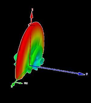
9 Example: Pushed Excitations Procedure Simulate 3D HFSS design Create system schematic, including active circuitry in Schematic Dynamically link HFSS Using Nexxim Circuit, solve linear system Pushes true magnitudes and phases back into HFSS for far field calculation. Benefit Obtain a realistic far field pattern based on the actual magnitudes and phases presented to antenna input ports Better understanding of what happens in non-ideal excitation scenarios Ability to incorporate compensation schemes into design Example: Phase imbalance associated with power amplifier compression in a transmit channel Baseline (HFSS Only) Compression modeled with HFSS + Circuit ANSYS, Inc.


10 Linear Circuit with Optimetrics Featured Optimetrics Capabilities: Parametric Analysis Optimization Tuning Sensitivity Analysis Initial S 11 goal ANSYS, Inc.


11 Circuit Design Utilities Transmission Line Calculator Filter Synthesis Load-Pull Utility Smith Tool: Matching Network Synthesis ANSYS, Inc.
12 This page intentionally left blank ANSYS, Inc.
Nonlinear Effects in Active Phased Array System Performance
 Nonlinear Effects in Active Phased Array System Performance Larry Williams, PhD Director of Product Management ANSYS Inc. 1 Advanced Simulation Simulate the Complete Product Real-life behavior in real-world
Ansys Designer RF Training Lecture 3: Nexxim Circuit Analysis for RF
 Ansys Designer RF Solutions for RF/Microwave Component and System Design 7. 0 Release Ansys Designer RF Training Lecture 3: Nexxim Circuit Analysis for RF Designer Overview Ansoft Designer Advanced Design
Modular High Power Ku-Band Polarisation Devices for Space Applications. Philipp Kohl
 Modular High Power Ku-Band Polarisation Devices for Space Applications Philipp Kohl 28-29.04.2015 Outline Motivation Mission Scenarios Investigated Polarisation Devices Polarisation Device Principle Requirements
LOW COST PHASED ARRAY ANTENNA TRANSCEIVER FOR WPAN APPLICATIONS
 LOW COST PHASED ARRAY ANTENNA TRANSCEIVER FOR WPAN APPLICATIONS Introduction WPAN (Wireless Personal Area Network) transceivers are being designed to operate in the 60 GHz frequency band and will mainly
RFVC1800 Wideband MMIC VCO with Buffer Amplifier 8GHz to 12GHz
 Wideband MMIC VCO with Buffer Amplifier 8GHz to 12GHz RFMD s wideband voltage controlled oscillator is a GaAs InGaP HBT MMIC with integrated VCO core and RF output buffer. The part operates from a single
Highly Accurate and Robust Automotive Radar System Design. Markus Kopp Lead Application Specialist ANSYS Inc.
 Highly Accurate and Robust Automotive Radar System Design Markus Kopp Lead Application Specialist ANSYS Inc. Introduction This presentation is an overview of a proposed design methodology for automotive
Response Surface Channel Modeling Designer SI & DesignXplorer
 Response Surface Channel Modeling Designer SI & DesignXplorer 1 ANSYS, Inc. September 14, Outline Product Introductions Designer SI DesignXplorer Intro to DOE & Response Surface Modeling Response Surfaces
When Should You Apply 3D Planar EM Simulation?
 When Should You Apply 3D Planar EM Simulation? Agilent EEsof EDA IMS 2010 MicroApps Andy Howard Agilent Technologies 1 3D planar EM is now much more of a design tool Solves bigger problems and runs faster
SmartSpice RF Harmonic Balance Based RF Simulator. Advanced RF Circuit Simulation
 SmartSpice RF Harmonic Balance Based RF Simulator Advanced RF Circuit Simulation SmartSpice RF Overview Uses harmonic balance approach to solve system equations in frequency domain Well suited for RF and
CHAPTER - 6 PIN DIODE CONTROL CIRCUITS FOR WIRELESS COMMUNICATIONS SYSTEMS
 CHAPTER - 6 PIN DIODE CONTROL CIRCUITS FOR WIRELESS COMMUNICATIONS SYSTEMS 2 NOTES 3 INTRODUCTION PIN DIODE CONTROL CIRCUITS FOR WIRELESS COMMUNICATIONS SYSTEMS Chapter 6 discusses PIN Control Circuits
Synthesis of Optimal On-Chip Baluns
 Synthesis of Optimal On-Chip Baluns Sharad Kapur, David E. Long and Robert C. Frye Integrand Software, Inc. Berkeley Heights, New Jersey Yu-Chia Chen, Ming-Hsiang Cho, Huai-Wen Chang, Jun-Hong Ou and Bigchoug
RF Circuit Synthesis for Physical Wireless Design
 RF Circuit Synthesis for Physical Wireless Design Overview Subjects Review Of Common Design Tasks Break Down And Dissect Design Task Review Non-Synthesis Methods Show A Better Way To Solve Complex Design
Prediction of Co-site interference in complex RF environments
 Prediction of Co-site interference in complex RF environments Frank Demming-Janssen CST AG The Cosite Scenario Multiple RF systems co-located in a common environment Diverse system characteristics Frequency
SmartSpice RF Harmonic Balance Based and Shooting Method Based RF Simulation
 SmartSpice RF Harmonic Balance Based and Shooting Method Based RF Simulation Silvaco Overview SSRF Attributes Harmonic balance approach to solve system of equations in frequency domain Well suited for
915 MHz Power Amplifier. EE172 Final Project. Michael Bella
 915 MHz Power Amplifier EE17 Final Project Michael Bella Spring 011 Introduction: Radio Frequency Power amplifiers are used in a wide range of applications, and are an integral part of many daily tasks.
RF Board Design for Next Generation Wireless Systems
 RF Board Design for Next Generation Wireless Systems Page 1 Introduction Purpose: Provide basic background on emerging WiMax standard Introduce a new tool for Genesys that will aide in the design and verification
insert link to the published version of your paper
 Citation Niels Van Thienen, Wouter Steyaert, Yang Zhang, Patrick Reynaert, (215), On-chip and In-package Antennas for mm-wave CMOS Circuits Proceedings of the 9th European Conference on Antennas and Propagation
EM/Circuit Co-simulation Vratislav Sokol
 EM/Circuit Co-simulation Vratislav Sokol 1 UGM 2009, Wednesday 18 th March, Darmstadt www.cst.com Agenda Motivation for EM/Circuit Co-simulation Standard versus Transient Co-simulation Standard Co-simulation
Analysis and design of lumped element Marchand baluns
 Downloaded from orbit.dtu.d on: Mar 14, 218 Analysis and design of lumped element Marchand baluns Johansen, Tom Keinice; Krozer, Vitor Published in: 17th International Conference on Microwaves, Radar and
LTE Small-Cell Base Station Antenna Matched for Maximum Efficiency
 Application Note LTE Small-Cell Base Station Antenna Matched for Maximum Efficiency Overview When designing antennas for base stations and mobile devices, an essential step of the design process is to
Analog Devices Welcomes Hittite Microwave Corporation NO CONTENT ON THE ATTACHED DOCUMENT HAS CHANGED
 Analog Devices Welcomes Hittite Microwave Corporation NO CONTENT ON THE ATTACHED DOCUMENT HAS CHANGED www.analog.com www.hittite.com THIS PAGE INTENTIONALLY LEFT BLANK Typical Applications Low noise wideband
PRODUCT APPLICATION NOTES
 Extending the HMC189MS8 Passive Frequency Doubler Operating Range with External Matching General Description The HMC189MS8 is a miniature passive frequency doubler in a plastic 8-lead MSOP package. The
--- An integrated 3D EM design flow for EM/Circuit Co-Design
 ADS users group meeting 2009 Rome 13/05, Böblingen 14-15/05, Massy 16/06 --- An integrated 3D EM design flow for EM/Circuit Co-Design Motivations and drivers for co-design Throw-The-Die-Over-The-Wall,
DESIGN OF HIGH POWER AND EFFICIENT RF LDMOS PA FOR ISM APPLICATIONS
 DESIGN OF HIGH POWER AND EFFICIENT RF LDMOS PA FOR ISM APPLICATIONS Farhat Abbas and John Gajadharsing NXP Semiconductors Nijmegen, The Netherlands Farhat.abbas@nxp.com Very high performance in power and
Design and Matching of a 60-GHz Printed Antenna
 Application Example Design and Matching of a 60-GHz Printed Antenna Using NI AWR Software and AWR Connected for Optenni Figure 1: Patch antenna performance. Impedance matching of high-frequency components
ELEC4604. RF Electronics. Experiment 2
 ELEC4604 RF Electronics Experiment MICROWAVE MEASUREMENT TECHNIQUES 1. Introduction and Objectives In designing the RF front end of a microwave communication system it is important to appreciate that the
The wireless industry
 From May 2007 High Frequency Electronics Copyright Summit Technical Media, LLC RF SiP Design Verification Flow with Quadruple LO Down Converter SiP By HeeSoo Lee and Dean Nicholson Agilent Technologies
Methodology for MMIC Layout Design
 17 Methodology for MMIC Layout Design Fatima Salete Correra 1 and Eduardo Amato Tolezani 2, 1 Laboratório de Microeletrônica da USP, Av. Prof. Luciano Gualberto, tr. 3, n.158, CEP 05508-970, São Paulo,
Designing Next-Generation AESA Radar Part 2: Individual Antenna Design
 Design Designing Next-Generation AESA Radar Part 2: Individual Antenna Design Figure 8: Antenna design Specsheet user interface showing the electrical requirements input (a), physical constraints input
Modeling and Simulation of Via Conductor Losses in Co-fired Ceramic Substrates Used In Transmit/Receive Radar Modules
 Modeling and Simulation of Via Conductor Losses in Co-fired Ceramic Substrates Used In Transmit/Receive Radar Modules 4/5/16 Rick Sturdivant, CTO 310-980-3039 rick@rlsdesigninc.com Edwin K.P. Chong, Professor
Large Scale Antenna Systems (Massive MIMO)
") Large Scale Antenna Systems (Massive MIMO) Capacity( bτs) = NBlog 2 1 + S N + I Contiguous available bandwidth Additional channels due to huge number of antennas Optimized Signal to Noise+Interference
Large Scale Antenna Systems (Massive MIMO) Capacity( bτs) = NBlog 2 1 + S N + I Contiguous available bandwidth Additional channels due to huge number of antennas Optimized Signal to Noise+Interference
Aperture Tuning: An Essential Technology in 5G Smartphones
 WHITE PAPER Aperture Tuning: An Essential Technology in 5G Smartphones By Abhinay Kuchikulla Senior Marketing Manager, Mobile Products Executive Summary Antenna aperture tuning is essential to enable smartphones
Design Services Capability WiWo Tech Systems Pvt Ltd
 iotech Design Services Capability io Tech Pvt Ltd Company Profile iotech iotech Private Ltd is an Engineering design services company located in Bangalore iotech supports Engineering design services in
77 GHz VCO for Car Radar Systems T625_VCO2_W Preliminary Data Sheet
 77 GHz VCO for Car Radar Systems Preliminary Data Sheet Operating Frequency: 76-77 GHz Tuning Range > 1 GHz Output matched to 50 Ω Application in Car Radar Systems ESD: Electrostatic discharge sensitive
Vector Network Analyzer Application note
 Vector Network Analyzer Application note Version 1.0 Vector Network Analyzer Introduction A vector network analyzer is used to measure the performance of circuits or networks such as amplifiers, filters,
Application of the Ansoft Serenade 7.0 PC Software in a Wireless Course
 Session 2520 Application of the Ansoft Serenade 7.0 PC Software in a Wireless Course Willie K. Ofosu Telecommunications Department Penn State Wilkes-Barre Abstract Wireless applications have experienced
325 to 500 GHz Vector Network Analyzer System
 325 to 500 GHz Vector Network Analyzer System By Chuck Oleson, Tony Denning and Yuenie Lau OML, Inc. Abstract - This paper describes a novel and compact WR-02.2 millimeter wave frequency extension transmission/reflection
Research Article Wideband Microstrip 90 Hybrid Coupler Using High Pass Network
 Microwave Science and Technology, Article ID 854346, 6 pages http://dx.doi.org/1.1155/214/854346 Research Article Wideband Microstrip 9 Hybrid Coupler Using High Pass Network Leung Chiu Department of Electronic
Using Accurate Component Models to Achieve First-Pass Success in Filter Design
 Application Example Using Accurate Component Models to Achieve First-Pass Success in Filter Design Overview Utilizing models that include component and printed circuit board (PCB) parasitics in place of
Accurate simulation and experimental validation of a 4-by-4 antenna array for Ka band
 Accurate simulation and experimental validation of a 4-by-4 antenna array for Ka band CST EUC 2016 - Strasbourg B. Lesur, M. Thévenot, T. Monédière, C. Mellé Outline Introduction Context Objectives Design
Features. = +25 C, Vdc = +12V
 Typical Applications The VCO Module is ideal for: Industrial/Medical Equipment Test & Measurement Equipment Military Radar, EW & ECM Lab Instrumentation Functional Diagram Electrical Specifications, T
5.8 GHz Charge Pump Receiver
 1 5.8 GHz Charge Pump Receiver Mitch Costley, Sen-wen Hsiao, Wasif Khan, and Mehdi Kiani T I. INTRODUCTION he number of RF signals pervading urban and suburban areas today presents a non-trivial amount
Vector-Receiver Load Pull Measurement
 MAURY MICROWAVE CORPORATION Vector-Receiver Load Pull Measurement Article Reprint of the Special Report first published in The Microwave Journal February 2011 issue. Reprinted with permission. Author:
ETSI Standards and the Measurement of RF Conducted Output Power of Wi-Fi ac Signals
 ETSI Standards and the Measurement of RF Conducted Output Power of Wi-Fi 802.11ac Signals Introduction The European Telecommunications Standards Institute (ETSI) have recently introduced a revised set
S.A. Torchinsky, A. van Ardenne, T. van den Brink-Havinga, A.J.J. van Es, A.J. Faulkner (eds.) 4-6 November 2009, Château de Limelette, Belgium
 4-6 November 2009, Château de Limelette, Belgium") WIDEFIELD SCIENCE AND TECHNOLOGY FOR THE SKA SKADS CONFERENCE 29 S.A. Torchinsky, A. van Ardenne, T. van den Brink-Havinga, A.J.J. van Es, A.J. Faulkner (eds.) 4-6 November 29, Château de Limelette, Belgium
WIDEFIELD SCIENCE AND TECHNOLOGY FOR THE SKA SKADS CONFERENCE 29 S.A. Torchinsky, A. van Ardenne, T. van den Brink-Havinga, A.J.J. van Es, A.J. Faulkner (eds.) 4-6 November 29, Château de Limelette, Belgium
Agilent Technologies Gli analizzatori di reti della serie-x
 Agilent Technologies Gli analizzatori di reti della serie-x Luigi Fratini 1 Introducing the PNA-X Performance Network Analyzer For Active Device Test 500 GHz & beyond! 325 GHz 110 GHz 67 GHz 50 GHz 43.5
A 2.4 GHZ RECEIVER IN SILICON-ON-SAPPHIRE MICHAEL PETERS. B.S., Kansas State University, 2009 A REPORT
 A 2.4 GHZ RECEIVER IN SILICON-ON-SAPPHIRE by MICHAEL PETERS B.S., Kansas State University, 2009 A REPORT submitted in partial fulfillment of the requirements for the degree MASTER OF SCIENCE Department
RFVC GHz to 12.1GHz MMIC VCO with Fo/2 and Fo/4 Outputs
 10.8GHz to 12.1GHz MMIC VCO with Fo/2 and Fo/4 Outputs RFMD's RFVC1844 is a 5V InGaP MMIC VCO with an integrated frequency divider providing additional Fo/2 and Fo/4 outputs. With an Fo frequency range
Multilayer chip antenna application guide
 1. introduction Shenzhen Sunlord electronics Co. LTD Multilayer chip antenna application guide The chip antenna series is designed for the applications of ISM band 2.4GHz and CMMB, just like as Bluetooth
UNIT-3. Electronic Measurements & Instrumentation
 UNIT-3 1. Draw the Block Schematic of AF Wave analyzer and explain its principle and Working? ANS: The wave analyzer consists of a very narrow pass-band filter section which can Be tuned to a particular
Diplexers With Cross Coupled Structure Between the Resonators Using LTCC Technology
 Proceedings of the 2007 WSEAS Int. Conference on Circuits, Systems, Signal and Telecommunications, Gold Coast, Australia, January 17-19, 2007 130 Diplexers With Cross Coupled Structure Between the Resonators
Design and RF Measurements of an X-band Accelerating Structure for the Sparc Project
 Design and RF Measurements of an X-band Accelerating Structure for the Sparc Project INFN-LNF ; UNIVERSITY OF ROME LA SAPIENZA ; INFN - MI Presented by BRUNO SPATARO Erice, Sicily, October 9-14; 2005 SALAF
Research Article Harmonic-Rejection Compact Bandpass Filter Using Defected Ground Structure for GPS Application
 Active and Passive Electronic Components, Article ID 436964, 4 pages http://dx.doi.org/10.1155/2014/436964 Research Article Harmonic-Rejection Compact Bandpass Filter Using Defected Ground Structure for
RFVC1843TR7. 9.8GHz to 11.3GHz MMIC VCO with Fo/2 and Fo/4 Outputs. Features. Applications. Ordering Information
 RFVC1843 9.8GHz to 11.3GHz MMIC VCO with Fo/2 and Fo/4 Outputs RFMD's RFVC1843 is a 5V InGaP MMIC VCO with an integrated frequency divider providing additional Fo/2 and Fo/4 outputs. With an Fo frequency
Circular polarization 10GHz slot antenna
 Circular polarization 10GHz slot antenna Agilent Momentum&EMDS Nicolae CRISAN, PhD 1 Objectives: Design a rectangular microstrip slot antenna Geometry: square 11.9x11.9 [mm] Two input ports: 50 [Ohm] Dielectric:
Evaluation of Package Properties for RF BJTs
 Application Note Evaluation of Package Properties for RF BJTs Overview EDA simulation software streamlines the development of digital and analog circuits from definition of concept and estimation of required
LTCC Chip Antennas How to maximize performance
 LTCC Chip Antennas How to maximize performance Outline Chip Antenna Characteristics Antenna Selection Considerations Circuit Design Constraints Layout Tips Ultimate Goal To Maximize Performance Motivation
To design Phase Shifter. To design bias circuit for the Phase Shifter. Realization and test of both circuits (Doppler Simulator) with
 with") Prof. Dr. Eng. Klaus Solbach Department of High Frequency Techniques University of Duisburg-Essen, Germany Presented by Muhammad Ali Ashraf Muhammad Ali Ashraf 2226956 Outline 1. Motivation 2. Phase Shifters
Prof. Dr. Eng. Klaus Solbach Department of High Frequency Techniques University of Duisburg-Essen, Germany Presented by Muhammad Ali Ashraf Muhammad Ali Ashraf 2226956 Outline 1. Motivation 2. Phase Shifters
Transmit Power Extension Power Combiners/Splitters Figure 1 Figure 2
 May 2010 Increasing the Maximum Transmit Power Rating of a Power Amplifier Using a Power Combining Technique By Tom Valencia and Stephane Wloczysiak, Skyworks Solutions, Inc. Abstract Today s broadband
TETRA Tx Test Solution
 Product Introduction TETRA Tx Test Solution Signal Analyzer Reference Specifications ETSI EN 300 394-1 V3.3.1(2015-04) / Part1: Radio ETSI TS 100 392-2 V3.6.1(2013-05) / Part2: Air Interface May. 2016
MEMS And Advanced Radar
 MEMS And Advanced Radar Dr. John K. Smith DARPA Tech 99: MEMS And Advanced Radar Page 1 Active ESA DARPA Tech 99: MEMS And Advanced Radar Page 2 T / R Module TX Controller Logic RX DARPA Tech 99: MEMS
6.101 Project Proposal April 9, 2014 Kayla Esquivel and Jason Yang. General Outline
 6.101 Project Proposal April 9, 2014 Kayla Esquivel and Jason Yang General Outline We will build a superheterodyne AM Radio Receiver circuit that will have a bandwidth of the entire AM spectrum, and whose
Keywords: ISM, RF, transmitter, short-range, RFIC, switching power amplifier, ETSI
 Maxim > Design Support > Technical Documents > Application Notes > Wireless and RF > APP 4929 Keywords: ISM, RF, transmitter, short-range, RFIC, switching power amplifier, ETSI APPLICATION NOTE 4929 Adapting
RF/Microwave Amplifier Design Using Harmonic Balance Simulation With Only S-parameter Data
 Application Note RF/Microwave Amplifier Design Using Harmonic Balance Simulation With Only S-parameter Data Overview It is widely held that S-parameters combined with harmonic balance (HB) alone cannot
March 4-7, 2018 Hilton Phoenix / Mesa Hotel Mesa, Arizona Archive
 March 4-7, 2018 Hilton Phoenix / Mesa Hotel Mesa, Arizona Archive 2018 BiTS Workshop Image: pilgrims49 / istock COPYRIGHT NOTICE The presentation(s)/poster(s) in this publication comprise the Proceedings
Using an Arbitrary Waveform Generator for Threat Generation
 Application Note - Using an Arbitrary Waveform Generator for Threat Generation Authors: Mark Elo, Giga-tronics & Christopher Loberg, Tektronix Published: August 1, 2015 Revision: A Introduction An arbitrary
Phased Array Polarization Switches
 APPLICATION NOTE March 2003 Page 1 of 9 Application Note POL-1 Phased Array Polarization Switches PREPARED BY: EMS TECHNOLOGIES, INC. SPACE AND TECHNOLOGY - ATLANTA 660 ENGINEERING DRIVE P.O. BOX 7700
Hot S 22 and Hot K-factor Measurements
 Application Note Hot S 22 and Hot K-factor Measurements Scorpion db S Parameter Smith Chart.5 2 1 Normal S 22.2 Normal S 22 5 0 Hot S 22 Hot S 22 -.2-5 875 MHz 975 MHz -.5-2 To Receiver -.1 DUT Main Drive
ELECTRONICALLY SCANNED ARRAYS USING MICRO ELECTRO MECHANICAL SWITCH (MEMS) TECHNOLOGY
 TECHNOLOGY") ELECTRONICALLY SCANNED ARRAYS USING MICRO ELECTRO MECHANICAL SWITCH (MEMS) TECHNOLOGY Mark L. Pugh John K. Smith Air Force Research Laboratory Defense Research Projects Agency 32 Brooks Road 370 North
ELECTRONICALLY SCANNED ARRAYS USING MICRO ELECTRO MECHANICAL SWITCH (MEMS) TECHNOLOGY Mark L. Pugh John K. Smith Air Force Research Laboratory Defense Research Projects Agency 32 Brooks Road 370 North
ARL-TN-0835 July US Army Research Laboratory
 ARL-TN-0835 July 2017 US Army Research Laboratory Gallium Nitride (GaN) Monolithic Microwave Integrated Circuit (MMIC) Designs Submitted to Air Force Research Laboratory (AFRL)- Sponsored Qorvo Fabrication
Design of Duplexers for Microwave Communication Systems Using Open-loop Square Microstrip Resonators
 International Journal of Electromagnetics and Applications 2016, 6(1): 7-12 DOI: 10.5923/j.ijea.20160601.02 Design of Duplexers for Microwave Communication Charles U. Ndujiuba 1,*, Samuel N. John 1, Taofeek
Design and Investigation of Circular Polarized Rectangular Patch Antenna
 Design and Investigation of Circular Polarized Rectangular Patch Antenna Rajkumar 1 and Divyanshu Rao 2 1Shri Ram Institute Technology, Jabalpur (M.P.),India 2Prof. Divyanshu Rao, Shri Ram Institute Technology,
Holography Transmitter Design Bill Shillue 2000-Oct-03
 Holography Transmitter Design Bill Shillue 2000-Oct-03 Planned Photonic Reference Distribution for Test Interferometer The transmitter for the holography receiver is made up mostly of parts that are already
Research Article Compact and Wideband Parallel-Strip 180 Hybrid Coupler with Arbitrary Power Division Ratios
 Microwave Science and Technology Volume 13, Article ID 56734, 1 pages http://dx.doi.org/1.1155/13/56734 Research Article Compact and Wideband Parallel-Strip 18 Hybrid Coupler with Arbitrary Power Division
LTCC-Breitband-Balun. für einen Gegentaktverstärker
 LTCC @ IMST LTCC-Breitband-Balun für einen Gegentaktverstärker Dr. Jürgen Kassner, RF-Modules Reinhard Kulke, RF-Modules Dr. Andreas Lauer, Field Simulation and Modelling Dr. Dietmar Köther, Measurement
4GHz / 6GHz Radiation Measurement System
 4GHz / 6GHz Radiation Measurement System The MegiQ Radiation Measurement System (RMS) is a compact test system that performs 3-axis radiation pattern measurement in non-anechoic spaces. With a frequency
Thank you for downloading one of our ANSYS whitepapers we hope you enjoy it.
 Thank you! Thank you for downloading one of our ANSYS whitepapers we hope you enjoy it. Have questions? Need more information? Please don t hesitate to contact us! We have plenty more where this came from.
Doppler Simulator for 10 GHz Doppler Radar
 Doppler Simulator for 10 GHz Doppler Radar Presented by Ngeok Kuan Wai 2252462 Supervised by Prof. Dr.-Ing. K. Solbach Outline Motivation Doppler Radar and Doppler Simulator Phase shifter Other Electronic
A low cost signal generator for 54 MHz to 13.4 GHz. Matthias Bopp DD1US
 A low cost signal generator for 54 MHz to 13.4 GHz Matthias Bopp DD1US Microwave & EME Symposium in Gajow / Poland, June 9 th 2018 Agenda Motivation ADF5355 IC Chinese low cost modules Module including
Table of Contents. About SAGE Millimeter, Inc...1 Radar basics and related SAGE Millimeter microwave sensor technologies... 2
 A. INTRODUCTION About SAGE Millimeter, Inc.....1 Radar basics and related SAGE Millimeter microwave sensor technologies... 2 B. OSOCILLATORS (SOL Series) K band mechanically tuned Gunn oscillators......5
A 600 GHz Varactor Doubler using CMOS 65nm process
 A 600 GHz Varactor Doubler using CMOS 65nm process S.H. Choi a and M.Kim School of Electrical Engineering, Korea University E-mail : hyperleonheart@hanmail.net Abstract - Varactor and active mode doublers
Application Note 5525
 Using the Wafer Scale Packaged Detector in 2 to 6 GHz Applications Application Note 5525 Introduction The is a broadband directional coupler with integrated temperature compensated detector designed for
ECEN 4634/5634, MICROWAVE AND RF LABORATORY
 ECEN 4634/5634, MICROWAVE AND RF LABORATORY Final Exam December 18, 2017 7:30-10:00pm 150 minutes, closed book, 1 sheet allowed, no calculators (estimates need to be within 3dB) Part 1 (60%). Briefly answer
CHAPTER 3 DESIGN OF MICROSTRIP PATCH ARRAY ANTENNA
 CHAPTER 3 DESIGN OF MICROSTRIP PATCH ARRAY ANTENNA 3.1 Introduction This chapter is discussed on the various factors that affect the design of microstrips patch array antenna. This chapter will covered
Manufacturers of RF and Microwave Components and Assemblies Specialist in RF Filters, Power amplifiers and RF Switches
 Manufacturers of RF and Microwave Components and Assemblies Specialist in RF Filters, Power amplifiers and RF Switches sales@cormic.com www.cormic.com P 724.940.7556 F 724.940.7707 RF & MICROWAVE FILTERS
5G Multi-Band Vector Transceiver
 SOLUTION BRIEF Streamlining high-volume test of 5G NR base stations 5G Multi-Band Vector Transceiver Compact, scalable solution accelerates deployment of 5G equipment 5G New Radio (NR) network equipment
Leveraging High-Accuracy Models to Achieve First Pass Success in Power Amplifier Design
 Application Note Leveraging High-Accuracy Models to Achieve First Pass Success in Power Amplifier Design Overview Nonlinear transistor models enable designers to concurrently optimize gain, power, efficiency,
MSAN-001 X-Band Microwave Motion Sensor Module Application Note
 1. Introduction HB Series of microwave motion sensor modules are X-Band Mono-static DRO Doppler transceiver front-end module. These modules are designed for movement detection. They can be used in intruder
RF AND MICROWAVE ENGINEERING
 RF AND MICROWAVE ENGINEERING FUNDAMENTALS OF WIRELESS COMMUNICATIONS Frank Gustrau Dortmund University of Applied Sciences and Arts, Germany WILEY A John Wiley & Sons, Ltd., Publication Preface List of
Some Thoughts on Electronic T/R Circuits
 Some Thoughts on Electronic T/R Circuits Wes Hayward, w7zoi, November 3, 2018 Abstract: Several schemes have been used to switch an antenna between a receiver and transmitter. A popular scheme with low
Design of Class F Power Amplifiers Using Cree GaN HEMTs and Microwave Office Software to Optimize Gain, Efficiency, and Stability
 White Paper Design of Class F Power Amplifiers Using Cree GaN HEMTs and Microwave Office Software to Optimize Gain, Efficiency, and Stability Overview This white paper explores the design of power amplifiers
Dr.-Ing. Ulrich L. Rohde
 Dr.-Ing. Ulrich L. Rohde Noise in Oscillators with Active Inductors Presented to the Faculty 3 : Mechanical engineering, Electrical engineering and industrial engineering, Brandenburg University of Technology
ECEN 5014, Spring 2009 Special Topics: Active Microwave Circuits Zoya Popovic, University of Colorado, Boulder
 ECEN 5014, Spring 2009 Special Topics: Active Microwave Circuits Zoya opovic, University of Colorado, Boulder LECTURE 3 MICROWAVE AMLIFIERS: INTRODUCTION L3.1. TRANSISTORS AS BILATERAL MULTIORTS Transistor
Efficient Electromagnetic Analysis of Spiral Inductor Patterned Ground Shields
 Efficient Electromagnetic Analysis of Spiral Inductor Patterned Ground Shields James C. Rautio, James D. Merrill, and Michael J. Kobasa Sonnet Software, North Syracuse, NY, 13212, USA Abstract Patterned
Design of a BAW Quadplexer Module Using NI AWR Software
 Application Note Design of a BAW Quadplexer Module Using NI AWR Software Overview With the development of the LTE-Advanced and orthogonal frequency division multiple access (OFDMA) techniques, multiple
300 frequencies is calculated from electromagnetic analysis at only four frequencies. This entire analysis takes only four minutes.
 Electromagnetic Analysis Speeds RFID Design By Dr. James C. Rautio Sonnet Software, Inc. Liverpool, NY 13088 (315) 453-3096 info@sonnetusa.com http://www.sonnetusa.com Published in Microwaves & RF, February
The Design of A 125W L-Band GaN Power Amplifier
 Sheet Code RFi0613 White Paper The Design of A 125W L-Band GaN Power Amplifier This paper describes the design and evaluation of a single stage 125W L-Band GaN Power Amplifier using a low-cost packaged
PA FAN PLATE ASSEMBLY 188D6127G1 SYMBOL PART NO. DESCRIPTION. 4 SBS /10 Spring nut. 5 19A702339P510 Screw, thread forming, flat head.
 MAINTENANCE MANUAL 851-870 MHz, 110 WATT POWER AMPLIFIER 19D902797G5 TABLE OF CONTENTS Page DESCRIPTION.............................................. Front Page SPECIFICATIONS.................................................
Hot Topics and Cool Ideas in Scaled CMOS Analog Design
 Engineering Insights 2006 Hot Topics and Cool Ideas in Scaled CMOS Analog Design C. Patrick Yue ECE, UCSB October 27, 2006 Slide 1 Our Research Focus High-speed analog and RF circuits Device modeling,
Features. = +25 C, Vcc = +5V [1]
![Features. = +25 C, Vcc = +5V [1]](/thumbs/80/81652748.jpg "Features. = +25 C, Vcc = +5V [1]") Typical Applications Low Noise wideband MMIC VCO is ideal for: Features Wide Tuning Bandwidth Industrial/Medical Equipment Test & Measurement Equipment Military Radar, EW & ECM Functional Diagram Pout:
Typical Applications Low Noise wideband MMIC VCO is ideal for: Features Wide Tuning Bandwidth Industrial/Medical Equipment Test & Measurement Equipment Military Radar, EW & ECM Functional Diagram Pout: