vacon 20 complete user manual ac drives Phone: Fax: Web: -
|
|
|
- Tamsyn Bryan
- 6 years ago
- Views:
Transcription
1 vacon 20 ac drves complete user manual
2
3 Table of contents Document: DPD00716E1 Release date: Software package: FW0107V008.vcx 1.Safety 1 1.1Warnngs 1 1.2Safety nstructons 3 1.3Earthng and earth fault protecton 3 1.4Before runnng the motor 5 2.Recept of delvery 7 2.1Type desgnaton code 7 2.2Storage 7 2.3Mantenance Capactor recharge 8 2.4Warranty 9 2.5Manufacturer s declaraton of conformty 10 3.Installaton Mechancal nstallaton Vacon 20 dmensons Coolng Power losses EMC levels Changng the EMC protecton class from C2 or C3 to C Cablng and connectons Power cablng Control cablng Allowed opton boards n Vacon Screw of cables Cable and fuse specfcatons General cablng rules Strppng lengths of motor and mans cables Cable nstallaton and the UL standards Cable and motor nsulaton checks 44 4.Commssonng Commssonng steps of Vacon Fault tracng 47 6.Vacon 20 Applcaton Interface Introducton Control I / O 53 7.Control panel General Dsplay Keypad 56 1
4 7.4Navgaton on the Vacon 20 control panel Man menu Reference menu Montorng menu Parameter menu System menu 67 8.STANDARD applcaton parameters Quck setup parameters (Vrtual menu, shows when par = 1) Motor settngs (Control panel: Menu PAR -> P1) Start / stop setup (Control panel: Menu PAR -> P2) Frequency references (Control panel: Menu PAR -> P3) Ramps and brakes setup (Control panel: Menu PAR -> P4) Dgtal nputs (Control panel: Menu PAR -> P5) Analogue nputs (Control panel: Menu PAR -> P6) Pulse tran / Encoder (Control panel: Menu PAR -> P7) Dgtal outputs (Control panel: Menu PAR -> P8) Analogue outputs (Control panel: Menu PAR -> P9) Feldbus Data-Mappng (Control panel: Menu PAR -> P10) Prohbted Frequences (Control panel: Menu PAR -> P11) Lmt Supervsons (Control panel: Menu PAR -> P12) Protectons (Control panel: Menu PAR -> P13) Fault autoreset parameters (Control panel: Menu PAR -> P14) PID control parameters (Control panel: Menu PAR -> P15) Motor Pre-heat (Control panel: Menu PAR -> P16) Easy usage menu (Control panel: Menu PAR -> P17) System parameters 92 9.Parameter descrptons Motor settngs (Control panel: Menu PAR -> P1) Start / stop setup (Control panel: Menu PAR -> P2) Frequency references (Control panel: Menu PAR -> P3) Ramps & brakes setup (Control panel: Menu PAR -> P4) Dgtal nputs (Control panel: Menu PAR -> P5) Analogue nputs (Control panel: Menu PAR -> P6) Pulse tran / Encoder (Control panel: Menu PAR -> P7) Dgtal outputs (Control panel: Menu PAR -> P8) Analogue outputs (Control panel: Menu PAR -> P9) Feldbus Data-Mappng (Control panel: Menu PAR -> P10) Prohbted Frequences (Control panel: Menu PAR -> P11) Protectons (Control panel:menu Par->P13) Automatc reset (Control panel: Menu PAR -> P14) PID control parameters (Control panel: Menu PAR -> P15) 131 1
5 9.15Applcaton settng (Control panel: Menu PAR->P17) System parameter Modbus RTU Termnaton resstor Modbus address area Modbus process data Techncal data Vacon 20 techncal data Power ratngs Vacon 20 Mans voltage V Vacon 20 Mans voltage 115 V Vacon 20 Mans voltage V Vacon 20 Mans voltage 575 V Brake resstors 147 1
6 1
7 safety vacon 1 1. SAFETY ONLY A COMPETENT ELECTRICIAN IS ALLOWED TO CARRY OUT THE ELECTRICAL INSTALLATION! Ths manual contans clearly marked cautons and warnngs whch are ntended for your personal safety and to avod any unntentonal damage to the product or connected applances. Please read the nformaton ncluded n cautons and warnngs carefully: =Dangerous voltage Rsk of death or severe njury =General warnng Rsk of damage to the product or connected applances 1.1 Warnngs The components of the power unt of the frequency converter are lve when Vacon 20 s connected to mans. Comng nto contact wth ths voltage s extremely dangerous and may cause death or severe njury. The control unt s solated from the mans potental. The motor termnals U, V, W (T1, T2, T3) and the possble brake resstor termnals - / + are lve when Vacon 20 s connected to mans, even f the motor s not runnng. The control I / O-termnals are solated from the mans potental. However, the relay output termnals may have a dangerous control voltage present even when Vacon 20 s dsconnected from mans. The earth leakage current of Vacon 20 frequency converters exceeds 3.5 ma AC. Accordng to standard EN , a renforced protectve ground connecton must be ensured. If the frequency converter s used as a part of a machne, the machne manufacturer s responsble for provdng the machne wth a man swtch (EN ). If Vacon 20 s dsconnected from mans whle runnng the motor, t remans lve f the motor s energzed by the process. In ths case the motor functons as a generator feedng energy to the frequency converter. 1
8 2 vacon safety After dsconnectng the frequency converter from the mans, wat untl the fan stops and the ndcators on the dsplay go out. Wat 5 more mnutes before dong any work on Vacon 20 connectons. The motor can start automatcally after a fault stuaton, f the autoreset functon has been actvated. 1

9 safety vacon Safety nstructons The Vacon 20 frequency converter has been desgned for fxed nstallatons only. Do not perform any measurements when the frequency converter s connected to the mans. Do not perform any voltage wthstand tests on any part of Vacon 20. The product safety s fully tested at factory. Pror to measurements on the motor or the motor cable, dsconnect the motor cable from the frequency converter. Do not open the cover of Vacon 20. Statc voltage dscharge from your fngers may damage the components. Openng the cover may also damage the devce. If the cover of Vacon 20 s opened, warranty becomes vod. 1.3 Earthng and earth fault protecton The Vacon 20 frequency converter must always be earthed wth an earthng conductor connected to the earthng termnal. See fgure below: MI1 - MI3 1
10 4 vacon safety MI4 MI5 The earth fault protecton nsde the frequency converter protects only the converter tself aganst earth faults. If fault current protectve swtches are used they must be tested wth the drve wth earth fault currents that are possble to arse n fault stuatons. 1
11 safety vacon Before runnng the motor Checklst: Before startng the motor, check that the motor s mounted properly and ensure that the machne connected to the motor allows the motor to be started. Set the maxmum motor speed (frequency) accordng to the motor and the machne connected to t. Before reversng the motor shaft rotaton drecton make sure that ths can be done safely. Make sure that no power correcton capactors are connected to the motor cable. 1
12 6 vacon safety 1
13 recept of delvery vacon 7 2. RECEIPT OF DELIVERY After unpackng the product, check that no sgns of transport damages are to be found on the product and that the delvery s complete (compare the type desgnaton of the product to the code below). Should the drve have been damaged durng the shppng, please contact prmarly the cargo nsurance company or the carrer. If the delvery does not correspond to your order, contact the suppler mmedately. 2.1 Type desgnaton code VACON0020-1L OPTIONS Vacon 20 Input phase 1L = Sngle phase 3L = Three phases Output Current Input Voltage 1=115V 2 = V 4 = V 7 = 575V +Optons EMC2 QPES QFLG Language of the documentaton +DLCN = Chnese +DLNL = Dutch +DLCZ = Czech +DLNO = Norwegan +DLDE = German +DLPT = Portuguese +DLDK = Dansh +DLRU = Russan +DLES = Spansh +DLSE = Swedsh +DLFI = Fnnsh +DLTR = Turksh +DLFR = French +DLUS = US Englsh +DLIT = Italan empty = Englsh Fgure 2.1: Vacon 20 type desgnaton code 2.2 Storage If the frequency converter s to be kept n store before use make sure that the ambent condtons are acceptable: Storng temperature C Relatve humdty < 95%, no condensaton 2
14 8 vacon recept of delvery 2.3 Mantenance In normal operatng condtons, Vacon 20 frequency converters are mantenancefree. However, regular mantenance s recommended to ensure a trouble-free operatng and a long lfetme of the drve. We recommended to follow the table below for mantenance ntervals. Mantenance nterval Whenever necessary Regular 12 months (If stored) 6-24 months (dependng on envronment) * Only for frame 4 and frame 5 Mantenance acton Clean headsnk* Check tghtenng torques of termnals Check nput and output termnals and control I / O termnals. Clean coolng tunnel.* Check operaton of coolng fan, check for corroson on termnals, busbars and other surfaces.* Check and clean and clean coolng fans: Man fan* Intermnal fan* Capactor recharge After a longer storage tme the capactors need to be recharge n order to avod capactor damage. Possble hgh leakage current through the capactors must be lmted. The best way to acheve ths s to use a DC-power supply wth adjustable current lmt. 1) Set the current lmt to ma accordng to the sze of the drve. 2) Then connect the DC-power supply to the nput phase L1 and L2. 3) Then set the DC-voltage to the nomnal DC-voltage level of the (1.35*Un AC) and supply the converter for at least 1 h. If DC-voltage s not avalable and the unt has been stored much longer than 12 months deenergzed, consult the factory before connectng power. 2
15 recept of delvery vacon Warranty Only manufacturng defects are covered by the warranty. The manufacturer assumes no responsblty for damages caused durng or resultng from transport, recept of the delvery, nstallaton, commssonng or use. The manufacturer shall n no event and under no crcumstances be held responsble for damages and falures resultng from msuse, wrong nstallaton, unacceptable ambent temperature, dust, corrosve substances or operaton outsde the rated specfcatons. Nether can the manufacturer be held responsble for consequental damages. The Manufacturer's tme of warranty s 18 months from the delvery or 12 months from the commssonng whchever expres frst (Vacon Warranty Terms). The local dstrbutor may grant a warranty tme dfferent from the above. Ths warranty tme shall be specfed n the dstrbutor's sales and warranty terms. Vacon assumes no responsblty for any other warrantes than that granted by Vacon tself. In all matters concernng the warranty, please contact frst your dstrbutor. 2
16 10 vacon recept of delvery 2.5 Manufacturer s declaraton of conformty EU DECLARATION OF CONFORMITY We Manufacturer's name: Vacon Oyj Manufacturer's address: P.O.Box 25 Runsornte 7 FIN Vaasa Fnland hereby declare that the product Product name: Vacon 20 Frequency Converter Model desgnaton: Vacon201L00012 to Vacon 20 3L to Vacon203L00014 to has been desgned and manufactured n accordance wth the followng standards: Safety: EN (2009) (as relevant), EN (2007) EMC: EN (2004) and conforms to the relevant safety provsons of the Low Voltage Drectve 2006/95/EC and EMC Drectve 2004/108/EC. It s ensured through nternal measures and qualty control that the product conforms at all tmes to the requrements of the current Drectve and the relevant standards. In Vaasa, 30th of July, 2010 Vesa Las Presdent The year the CE markng was affxed:
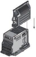
17 BACK RESET OK LOC REM BACK RESE T OK LOC REM BACK RESET OK LOC REM BACK RESE T OK LOC REM BACK RESET OK LOC REM nstallaton vacon INSTALLATION 3.1 Mechancal nstallaton There are two possble ways to mount Vacon 20 n the wall. For MI1-MI3, ether screw or DIN-ral mountng; For MI4-MI5, screw or flange mountng. MI1 =M4 MI2 =M5 MI3 M5 Fgure 3.1: Screw mountng, MI1 - MI3 MI4 =M 6 MI5 =M 6 Fgure 3.2: Screw mountng, MI4 - MI5 Note! See the mountng dmensons on the back of the drve. More detals n Chapter


18 BACK RESET OK LOC REM 12 vacon nstallaton 1 2 Fgure 3.3: DIN-ral mountng, MI1 - MI3 Fgure 3.4: Flange mountng, MI4 - MI5 3
19 nstallaton vacon 13 Fgure 3.5: Flange mountng cutout dmensons for MI4 (Unt: mm) Fgure 3.6: Flange mountng cutout dmensons for MI5 (Unt: mm) 3
20 14 vacon nstallaton MI4 MI5 Fgure 3.7: Flange mountng depth dmensons for MI4 and MI5 (Unt: mm) 3
21 nstallaton vacon Vacon 20 dmensons W2 W3 D2 H (H1) H2 H3 W (W1) D (D1) Fgure 3.8: Vacon 20 dmensons, MI1 - MI3 W2 W3 H (H1) H2 H3 W (W1) D (D1) Fgure 3.9: Vacon 20 dmensons, MI4 - MI5 3
22 16 vacon nstallaton Type H1 H2 H3 W1 W2 W3 D1 D2 MI MI MI MI MI Table 3.1: Vacon 20 dmensons n mllmetres Frame Dmensons(mm) Weght* W H D (kg.) MI MI MI MI MI *wthout shppng package Table 3.2: Vacon 20 frame dmensons (mm) and weghts (kg) Frame Dmensons(Inches) Weght* W H D (Ibs.) MI MI MI MI MI *wthout shppng package Table 3.3: Vacon 20 frame dmensons (Inch) and weghts (Ibs) 3
23 nstallaton vacon 17 Fgure 3.10: Vacon20 dmensons, MI2-3 Dsplay Locaton Dmensons (mm) MI2 Frame MI3 A B
24 18 vacon nstallaton Fgure 3.11: Vacon20 dmensons, MI4-5 Dsplay Locaton Dmensons (mm) MI2 Frame MI3 A B
25 nstallaton vacon Coolng Enough free space shall be left above and below the frequency converter to ensure suffcent ar crculaton and coolng. You wll fnd the requred dmensons for free space n the table below. If several unts are mounted above each other the requred free space equals C + D (see fgure below). Moreover, the outlet ar used for coolng by the lower unt must be drected away from the ar ntake of the upper unt. The amount of coolng ar requred s ndcated below. Also make sure that the temperature of the coolng ar does not exceed the maxmum ambent temperature of the converter. Mn clearance (mm) Type A* B* C D C MI MI MI MI MI Table 3.4: Mn. clearances around AC drve A A B B *. Mn clearance A and B for drves for MI1 ~ MI3 can be 0 mm f the ambent temperature s below 40 degrees. D Fgure 3.12: Installaton space A = clearance around the freq. converter (see also B) B = dstance from one frequency converter to another or dstance to cabnet wall C = free space above the frequency converter D = free space underneath the frequency converter NOTE! See the mountng dmensons on the back of the drve. Leave free space for coolng above (100 mm), below (50 mm), and on the sdes (20 mm) of Vacon 20! (For MI1 - MI3, sde-to-sde nstallaton allowed only f the ambent temperature s below 40 C; For MI4-MI5, sde-to-sde nstallaton s not allowed. Type Coolng ar requred (m³/h) MI1 10 MI2 10 MI3 30 MI4 45 MI5 75 Table 3.5: Requred coolng ar 3

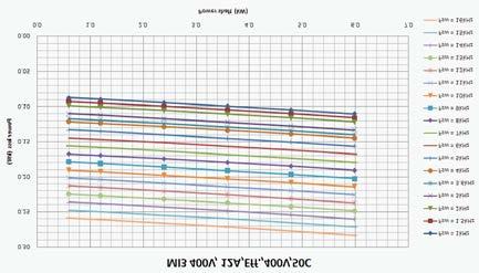
, ths nevtably affects the power losses and coolng")
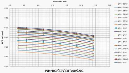
26 20 vacon nstallaton Power losses If the operator wants to rase the swtchng frequency of the drve for some reason (typcally e.g. n order to reduce the motor nose), ths nevtably affects the power losses and coolng requrements, for dfferent motor shaft power, operator can select the swtchng frequency accordng to the graphs below. MI1 - MI5 3P 380 V POWER LOSS 3
27 nstallaton vacon 21 3


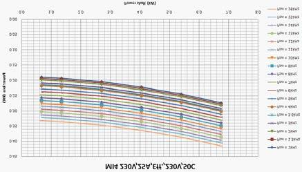
28 22 vacon nstallaton MI1 - MI5 3P 230 V POWER LOSS 3

29 nstallaton vacon 23 3
30 24 vacon nstallaton 3


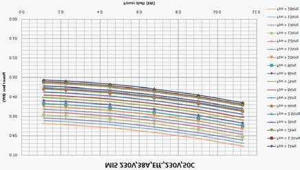
31 nstallaton vacon 25 MI1 - MI3 1P 230 V POWER LOSS 3

32 26 vacon nstallaton 3
33 nstallaton vacon EMC levels EN defnes the dvson of frequency converters nto four classes accordng to the level of electromagnetc dsturbances emtted, the requrements of a power system network and the nstallaton envronment (see below). The EMC class of each product s defned n the type desgnaton code. Category C1: Frequency converters of ths class comply wth the requrements of category C1 of the product standard EN (2004). Category C1 ensures the best EMC characterstcs and t ncludes converters the rated voltage of whch s less than 1000 V and whch are ntended for use n the 1st envronment. NOTE: The requrements of class C are fulflled only as far as the conducted emssons are concerned. Category C2: Frequency converters of ths class comply wth the requrements of category C2 of the product standard EN (2004). Category C2 ncludes converters n fxed nstallatons and the rated voltage of whch s less than 1000 V. The class C2 frequency converters can be used both n the 1st and the 2nd envronment. Category C3: Frequency converters of ths class comply wth the requrements of category C3 of the product standard EN (2004). Category C3 ncludes converters the rated voltage of whch s less than 1000 V and whch are ntended for use n the second envronment only. Category C4: The drves of ths class do not provde EMC emsson protecton. These knds of drves are mounted n enclosures. Envronments n product standard EN (2004) Frst envronment: Envronment that ncludes domestc premses. It also ncludes establshments drectly connected wthout ntermedate transformers to a low-voltage power supply network whch supples buldngs used for domestc purposes. NOTE: houses, apartments, commercal premses or offces n a resdental buldng are examples of frst envronment locatons. Second envronment: Envronment that ncludes all establshments other than those drectly connected to a low-voltage power supply network whch supples buldngs used for domestc purposes. NOTE: ndustral areas, techncal areas of any buldng fed from a dedcated transformer are examples of second envronment locatons. 3


34 28 vacon nstallaton Changng the EMC protecton class from C2 or C3 to C4 The EMC protecton class of MI1-3 frequency converters can be changed from class C2 or C3 to class C4 by removng the EMC-capactor dsconnectng screw, see fgure below. MI4 & 5 can also be changed by removng the EMC jumpers. Note! Do not attempt to change the EMC level back to class C2 or C3. Even f the procedure above s reversed, the frequency converter wll no longer fulfl the EMC requrements of class C2 / C3! Fgure 3.13: EMC protecton class, MI1 - MI3 Fgure 3.14: EMC protecton class, MI4 3

35 nstallaton vacon 29 Fgure 3.15: EMC protecton class, MI5 Fgure 3.16: Jumpers Remove the man cover and locate the two jumpers. Dsconnect the RFI-flters from ground by lftng the jumpers up from ther default postons. See Fgure
 1~ (230V) Motor out MAINS Strp the plastc cable coatng for 360 earthng MOTOR Fgure 3.")
 1~ (115V) Motor out L1 L2/N L3 R+ R- U/T1 V/T2 W/T3 MAINS BRAKE RESISTOR MOTOR Fgure 3.")
36 30 vacon nstallaton 3.2 Cablng and connectons Power cablng Note! Tghtenng torque for power cables s Nm (4-5 n.lbs). 3~ (230V, 400V) 1~ (230V) Motor out MAINS Strp the plastc cable coatng for 360 earthng MOTOR Fgure 3.17: Vacon 20 power connectons, MI1 3~(230V, 400V, 575V) External brake resstor 3~(230V, 400V, 575V) Strp the plastc cable coatng for 360 earthng 1~ (230V) 1~ (115V) Motor out L1 L2/N L3 R+ R- U/T1 V/T2 W/T3 MAINS BRAKE RESISTOR MOTOR Fgure 3.18: Vacon 20 power connectons, MI2 - MI3 3


37 nstallaton vacon 31 3~ (380, 480V) Motor out MAINS Brake RESISTOR MOTOR Fgure 3.19: Vacon 20 power connectons, MI4 3~ (380, 480V) Motor out MAINS Brake RESISTOR MOTOR Fgure 3.20: Vacon 20 power connectons, MI5 3


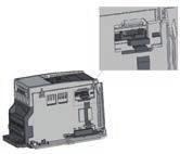
38 32 vacon nstallaton Control cablng Attach the support AFTER nstallng the power cables Attach ths plate BEFORE nstallng the power cables Fgure 3.21: Mount the PE-plate and API cable support, MI1 - MI3 3

39 nstallaton vacon 33 Attach the support AFTER nstallng Attach ths plate BEFORE nstallng the power cables Fgure 3.22: Mount the PE-plate and API cable support, MI4 - MI5 3

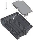
40 34 vacon nstallaton Fgure 3.23: Open the ld, MI1 - MI3 Fgure 3.24: Open the ld, MI4 - MI5 3


41 nstallaton vacon 35 Control cable tghtenng torque: 0.4 Nm Strp the plastc cable coatng for 360 earthng Fgure 3.25: Install the control cables. MI1 - MI3. See Chapter 6.2 Fgure 3.26: Install the control cables. MI4 - MI5. See Chapter 6.2 3


42 36 vacon nstallaton Allowed opton boards n Vacon20 See below for the allowed opton boards n the slot: Note! OPT-B1 and OPT-B4 only support external power supply. Opton board assembly structure:
43 nstallaton vacon
44 38 vacon nstallaton Screw of cables M4*8 Screws 12pcs Fgure 3.27: MI1 screws M4*8 Screws 10pcs Fgure 3.28: MI2 screws 3
45 nstallaton vacon 39 M4*8 Screws 10pcs Fgure 3.29: MI3 screws M4*10 Screws 4pcs M4*9 Screws 14pcs M4*17 Screws 6pcs Fgure 3.30: MI4 - MI5 screw 3
46 40 vacon nstallaton Cable and fuse specfcatons Use cables wth heat resstance of at least +70 C. The cables and the fuses must be dmensoned accordng to the tables below. Installaton of cables accordng to UL regulatons s presented n Chapter The fuses functon also as cable overload protecton. These nstructons apply only to cases wth one motor and one cable connecton from the frequency converter to the motor. In any other case, ask the factory for more nformaton. EMC category cat. C2 cat. C3 cat. C4 Mans cable types Motor cable types Control cable types Table 3.6: Cable types requred to meet standards. EMC categores are descrbed n Chapter Cable type Descrpton Power cable ntended for fxed nstallaton and the specfc mans voltage. Shelded cable not requred. (NKCABLES / MCMK or smlar recommended) Power cable equpped wth concentrc protecton wre and ntended for the specfc mans voltage. (NKCABLES / MCMK or smlar recommended). Power cable equpped wth compact low-mpedance sheld and ntended for the specfc mans voltage. (NKCABLES / MCCMK, SAB / ÖZCUY-J or smlar recommended). *360º earthng of both motor and FC connecton requred to meet the standard Screened cable equpped wth compact low-mpedance sheld (NKCA- 4 BLES /Jamak, SAB / ÖZCuY-O or smlar). Table 3.7: Cable type descrptons 3
47 nstallaton vacon 41 Frame Type Fuse [A] Mans cable Cu [mm 2 ] Motor cable Cu [mm 2 ] Termnal cable sze (mn/max) Man termnal [mm 2 ] Earth termnal [mm 2 ] Control termnal [mm 2 ] Relay termnal [mm 2 ] MI * * MI *6+6 3* Table 3.8: Cable and fuse szes for Vacon 20, 115 V, 1~ Frame Type Fuse [A] Mans cable Cu [mm 2 ] Motor cable Cu [mm 2 ] Termnal cable sze (mn/max) Man termnal [mm 2 ] Earth termnal [mm 2 ] Control termnal [mm 2 ] Relay termnal [mm 2 ] MI * * MI * * MI *6+6 3* Table 3.9: Cable and fuse szes for Vacon 20, V, 1~ Frame Type Fuse [A] Mans cable Cu [mm 2 ] Motor cable Cu [mm 2 ] Termnal cable sze (mn/max) Man termnal [mm 2 ] Earth termnal [mm 2 ] Control termnal [mm 2 ] Relay termnal [mm 2 ] MI * * MI * * MI * * MI *6+6 3* Cu MI * * Cu / Al Table 3.10: Cable and fuse szes for Vacon 20, V, 3~ 3
48 42 vacon nstallaton Frame Type Fuse [A] Mans cable Cu [mm 2 ] Motor cable Cu [mm 2 ] Termnal cable sze (mn/max) Man termnal [mm 2 ] Earth termnal [mm 2 ] Control termnal [mm 2 ] Relay termnal [mm 2 ] MI * * MI * * MI * * MI *6+6 3* Cu MI * * Cu / Al Table 3.11: Cable and fuse szes for Vacon 20, V, 3~ Frame Type Fuse [A] Mans cable Cu [mm 2 ] Motor cable Cu [mm 2 ] Termnal cable sze (mn/max) Man termnal [mm 2 ] Earth termnal [mm 2 ] Control termnal [mm 2 ] Relay termnal [mm 2 ] MI * * MI * * MI * * Table 3.12: Cable and fuse szes for Vacon 20, 575 V,3~ Note! To fulfl standard EN , the protectve co nductor should be at least 10 mm 2 Cu or 16 mm 2 Al. Another possblty s to use an addtonal protectve conductor of at least the same sze as the orgnal one. 3
49 nstallaton vacon General cablng rules 1 2 Before startng the nstallaton, check that none of the components of the frequency converter s lve. Place the motor cables suffcently far from other cables: Avod placng the motor cables n long parallel lnes wth other cables. If the motor cable runs n parallel wth other cables, the mnmum dstance between the motor cable and other cables s 0.3 m. The gven dstance also apples between the motor cables and sgnal cables of other systems. The maxmum length of the motor cables for MI1-3 s 30 m. For MI4 & 5, maxmum length s 50 m, f use longer cable, current accuracy wll be decreased. The motor cables should cross other cables at an angle of 90 degrees. 3 If cable nsulaton checks are needed, see Chapter Connectng the cables: Strp the motor and mans cables as advsed n Fgure Connect the mans, motor and control cables nto ther respectve termnals, see Fgures Note the tghtenng torques of power cables and control cables gven n chapter and For nformaton on cable nstallaton accordng to UL regulatons see Chapter Make sure that the control cable wres do not come n contact wth the electronc components of the unt. If an external brake resstor (opton) s used, connect ts cable to the approprate termnal. Check the connecton of the earth cable to the motor and the frequency converter termnals marked wth Connect the separate sheld of the motor cable to the earth plate of the frequency converter, motor and the supply centre. 3
50 44 vacon nstallaton Strppng lengths of motor and mans cables Earth conductor 8 mm 8 mm 35 mm 20 mm Fgure 3.31: Strppng of cables Note! Strp also the plastc cover of the cables for 360 degree earthng. See Fgures 3.17, 3.18 and Cable nstallaton and the UL standards To meet the UL (Underwrters Laboratores) regulatons, a UL-approved copper cable wth a mnmum heat-resstance of +60 / 75 C must be used Cable and motor nsulaton checks These checks can be performed as follows f motor or cable nsulatons are suspected to be faulty. 1. Motor cable nsulaton checks Dsconnect the motor cable from termnals U / T1, V / T2 and W / T3 of the frequency converter and from the motor. Measure the nsulaton resstance of the motor cable between each phase conductor as well as between each phase conductor and the protectve ground conductor. The nsulaton resstance must be >1 MOhm. 2. Mans cable nsulaton checks Dsconnect the mans cable from termnals L1, L2 / N and L3 of the frequency converter and from the mans. Measure the nsulaton resstance of the mans cable between each phase conductor as well as between each phase conductor and the protectve ground conductor. The nsulaton resstance must be >1 MOhm. 3. Motor nsulaton checks Dsconnect the motor cable from the motor and open the brdgng connectons n the motor connecton box. Measure the nsulaton resstance of each motor wndng. The measurement voltage must equal at least the motor nomnal voltage but not exceed 1000 V. The nsulaton resstance must be >1 MOhm. 3
51 commssonng vacon COMMISSIONING Before commssonng, read the warnngs and nstructons lsted n Chapter 1! 4.1 Commssonng steps of Vacon 20 1 Read carefully the safety nstructons n Chapter 1 and follow them. 2 After the nstallaton, make sure that: both the frequency converter and the motor are grounded. the mans and motor cables comply wth the requrements gven n Chapter the control cables are located as far as possble from the power. cables (see Chapter 3.2.6, step 2) and the shelds of the shelded cables are connected to protectve earth. 3 Check the qualty and quantty of coolng ar (Chapter 3.1.2). 4 Check that all Start / Stop swtches connected to the I / O termnals are n Stopposton. 5 Connect the frequency converter to mans. 6 Set the parameters of group 1 accordng to the requrements of your applcaton. At least the followng parameters should be set: motor nomnal speed (par. 1.3) motor nomnal current (par. 1.4) applcaton type (par. 17.1) You wll fnd the values needed for the parameters on the motor ratng plate. 4
52 46 vacon commssonng Perform test run wthout motor. Perform ether Test A or Test B: A) Control from the I / O termnals: Turn the Start/Stop swtch to ON poston. Change the frequency reference (potentometer). Check the Montorng Menu and make sure that the value of Output frequency changes accordng to the change of frequency reference. Turn the Start / Stop swtch to OFF poston. B) Control from the keypad: Select the keypad as the control place wth par 2.1. You can also move to keypad control by pressng Loc / Rem button or select Local control wth par 2.5. Push the Start button on the keypad. Check the Montorng Menu and make sure that the value of Output frequency. changes accordng to the change of frequency reference. Push the Stop button on the keypad. Run the no-load tests wthout the motor beng connected to the process, f possble. If ths s mpossble, secure the safety of each test pror to runnng t. Inform your co-workers of the tests. Swtch off the supply voltage and wat up untl the drve has stopped. Connect the motor cable to the motor and to the motor cable termnals of the frequency converter. See to that all Start / Stop swtches are n Stop postons. Swtch the mans ON. Repeat test 7A or 7B. Perform an dentfcaton run (see par. 1.18), especally f the applcaton requres a hgh startup torque or a hgh torque wth low speed. Connect the motor to the process (f the no-load test was runnng wthout the motor beng connected). Before runnng the tests, make sure that ths can be done safely. Inform your co-workers of the tests. Repeat test 7A or 7B. 4
53 fault tracng vacon FAULT TRACING When a fatal fault s detected by the frequency converter control electroncs, the drve wll stop and the symbol FT and the fault code blnked on the dsplay are n the followng format, e.g.: FT 2 Fault code (02 = overvoltage) The actve fault can be reset by pressng BACK / RESET button when the API s n actve fault menu level (FT XX), or pressng BACK / RESET button wth long tme (> 2 s) when the API s n actve fault submenu level (F5.x ), or va the I / O termnal or feld bus. Reset fault hstory (long push > 5 s), when the API s n fault hstory submenu level (F6.x). The faults wth subcode and tme labels are stored n the Fault hstory submenu whch can be browsed. The dfferent fault codes, ther causes and correctng actons are presented n the table below. Fault code Fault name Possble cause Correctng actons 1 Overcurrent 2 Overvoltage 3 Earth fault Table 5.1: Fault codes Frequency converter has detected too hgh a current (>4*I N ) n the motor cable: sudden heavy load ncrease short crcut n motor cables unsutable motor Check loadng. Check motor sze. Check cables. The DC-lnk voltage has exceeded the nternal safety lmt: Increase the deceleraton deceleraton tme s too short tme (Par.4.3 or Par.4.6) hgh overvoltage peaks n mans Current measurement has detected extra leakage current at Check motor cables and start: motor nsulaton falure n cables or motor 5
54 48 vacon fault tracng Fault code Fault name Possble cause Correctng actons 8 System fault component falure faulty operaton Reset the fault and restart. If the fault re-occurs, contact the dstrbutor near to you. NOTE! If fault F8 occurs, fnd out the subcode of the fault from the Fault Hstory menu under Id xxx! 9 Under voltage 11 Output phase fault Frequency converter under temperature Frequency converter over temperature 15 Motor stalled 16 Motor over temperature 17 Motor underload Table 5.1: Fault codes The DC-lnk voltage has gone below the nternal safety lmt: most probable cause: supply voltage s too low frequency converter nternal fault Power outages Current measurement has detected that there s no current n one motor phase. Heat snk temperature s under -10 C Heat snk s overheated. Motor stall protecton has trpped. In case of temporary supply voltage break reset the fault and restart the frequency converter. Check the supply voltage. If t s adequate, an nternal falure has occurred. Contact the dstrbutor near to you. Check motor cable and motor. Check the ambent temperature. Check that the coolng ar flow s not blocked. Check the ambent temperature. Clean the heatsnk dust. Make sure that the swtchng frequency s not too hgh n relaton to ambent temperature and motor load. Check that the motor s able to rotate freely. Motor overheatng has been Decrease the motor load. detected by frequency converter If no motor overload motor temperature model. Motor exsts, check the temperature model s overloaded. parameters. Motor underload protecton has trpped. Check motor and load, e.g. for broken belts or dry pumps. 5
55 fault tracng vacon 49 Fault code Fault name Possble cause Correctng actons 22 EEPROM checksum fault 25 Mcrocontroller watchdog fault 27 Back EMF protecton 29 Thermstor fault 34 Internal bus communcaton 35 Applcaton fault 41 IGBT Overtemperature 50 Analog nput select 20% - 100% (selected sgnal range 4 to 20 ma or 2 to 10 V) 51 External fault Table 5.1: Fault codes Parameter save fault faulty operaton component falure faulty operaton component falure Drve has detected that the magnetzed motor s runnng n start stuaton. A rotatng PM-motor The thermstor nput of opton board has detected ncrease of the motor temperature. Ambent nterference or defectve hardware. Applcaton s not workng properly. Overtemperature alarm s ssued when the IGBT swtch temperature exceeds 110 C. Current at the analogue nput s < 4mA; Voltage at the analogue nput s < 2 V. control cable s broken or loose. sgnal source has faled. Dgtal nput fault. Dgtal nput has been programmed as external fault nput and ths nput s actve. Contact the dstrbutor near to you. Reset the fault and restart. If the fault re-occur, contact the dstrbutor near to you. Make sure that there s no rotatng PM-motor when the start command s gven. Check motor coolng and loadng. Check thermstor connecton (If thermstor nput of the opton board s not n use t has to be short crcuted). If the fault re-occur, contact the dstrbutor near to you. Contact the dstrbutor near to you. Check loadng. Check motor sze. Make dentfcaton run. Check the current loop crcutry. Remove the external devce fault. 5
56 50 vacon fault tracng Fault code Fault name Possble cause Correctng actons 52 Door Panel fault Control place s keypad, but door panel has been dsconnected. Check the connecton between optonal board and API. If connecton s correct, contact the nearest Vacon dstrbutor. 53 Feldbus fault 54 Slot fault 55 Wrong run fault The data connecton between the feldbus Master and the feldbus of the drve has broken. The connecton between optonal board and API has been broken. Run forward and backward are hgh at the same tme. 57 Idenfcaton fault Identfcaton run has faled. Check nstallaton. If nstallaton s correct, contact the nearest Vacon dstrbutor. Check board and slot. Contact the nearest Vacon dstrbutor. Check I/O control sgnal 1 and I/O control sgnal 2. Run command was removed before completon of dentfcaton run. Motor s not connected to frequency converter. There s load on motor shaft. Check temperature sgnal 111 Temperature fault Over low or over hgh temperature from OPTBH board Table 5.1: Fault codes 5
57 vacon 20 ap vacon VACON 20 APPLICATION INTERFACE 6.1 Introducton There s only one verson of Control Board avalable for the Vacon 20 drve: Verson Vacon 20 Composton 6 Dgtal nputs 2 Analogue nputs 1 Analogue output 1 Dgtal output 2 Relay outputs RS-485 Interface Table 6.1: Avalable Control Board Ths secton provdes you wth a descrpton of the I / O-sgnals for Vacon 20 and nstructons for usng the Vacon 20 general purpose applcaton. The frequency reference can be selected from Preset Speed 0, Keypad, Feldbus, AI1, AI2, AI1+AI2, PID, Motor potentometer and Pulse tran / Encoder. Basc propertes: Dgtal nputs DI1 DI6 are freely programmable. The user can assgn a sngle nput to many functons. Dgtal-, relay- and analogue outputs are freely programmable. Analog output can be programmed as current or voltage output. Analog nput 1 can be as voltage nput,analog nput 2 can be programmed as current or voltage nput. DI5/6 can be used as pulse tran or Encoder. Specal features: Programmable Start / Stop and Reverse sgnal logc Motor pre-heat Reference scalng DC-brake at start and stop Programmable U / f curve Adjustable swtchng frequency Autoreset functon after fault 6
58 52 vacon vacon 20 ap Protectons and supervsons (all fully programmable; off, alarm, fault): Analog nput low fault External fault Undervoltage fault Earth fault Motor thermal, stall and underload protecton Feldbus communcaton Output phase fault Thermstor fault 8 preset speeds Analogue nput range selecton, sgnal scalng and flterng PID-controller 6
59 vacon 20 ap vacon Control I / O 1-10 k Termnal Sgnal Factory preset Descrpton Vref Ref. voltage out Maxmum load 10 ma 2 AI1 Analog sgnal n 1 Freq. reference P) 0-10 V, R >= 200 k 3 GND I / O sgnal ground 6 24 Vout 24 V output for DI's 20 %, max. load 50 ma ma 7 DI_C Dgtal Input Common 4 AI2 Analog sgnal n 2 PID actual value and Freq. reference P) Dgtal Input Common for DI1- DI6, refer to Table 6.3 for DI snk type 8 DI1 Dgtal nput 1 Start forward P) V, R > 5 k 9 DI2 Dgtal nput 2 Start reverse P) 10 DI3 Dgtal nput 3 Fault reset P) A A RS485 sgnal A FB Communcaton Negatve B B RS485 sgnal B FB Communcaton Postve Default: 0(4) - 20 ma, R <= 250 Other: 0-10 V, R >= 200 k Selectable through mcroswtch 5 GND I / O sgnal ground 13 DO- Dgtal Output Common Dgtal Output Common 14 DI4 Dgtal nput 4 Preset speed B0 P) V, R > 5 k 15 DI5 Dgtal nput 5 Preset speed B1 P) As DI, Other: Encoder Input A (frequency up to 10 khz) Selectable through mcroswtch 16 DI6 Dgtal nput 6 External Fault P) As DI, Other: Encoder Input B (frequency up to 10 khz), Pulse Tran Input (frequency up to 5 khz) 0-10 V, RL >1 K 18 AO Analog Output Output frequency P) 0(4) - 20 ma, RL < 500 Selectable through mcroswtch 20 DO Dgtal sgnal out Actve = READY P) Open collector, max. load 48 V / 50 ma Table 6.2: Vacon 20 General purpose applcaton default I / O confguraton and connectons for control board P) = Programmable functon, see parameter lsts and descrptons, chapters 8 and 9. 6
60 54 vacon vacon 20 ap Termnal Sgnal Factory preset Descrpton 22 RO 13 Relay out 1 23 RO 14 Actve = RUN P) 0.4 A 24 RO 22 Relay out 2 25 RO 21 Actve = FAULT P) 26 RO 24 Max. swtchng load: 250 Vac / 2 A or 250 Vdc / Max. swtchng load: 250 Vac / 2 A or 250 Vdc / 0.4 A Table 6.2: Vacon 20 General purpose applcaton default I / O confguraton and connectons for control board P) = Programmable functon, see parameter lsts and descrptons, chapters 8 and 9. Termnal Sgnal Factory preset Descrpton 3 GND I / O sgnal ground 6 24 Vout 24 V output for DI's 20 %, max. load 50 ma 7 DI_C Dgtal Input Common Dgtal Input Common for DI1-DI6 8 DI1 Dgtal nput 1 Start forward P) V, R > 5 k 9 DI2 Dgtal nput 2 Start reverse P) 10 DI3 Dgtal nput 3 Fault reset P) 14 DI4 Dgtal nput 4 Preset speed B0 P) V, R > 5 k 15 DI5 Dgtal nput 5 Preset speed B1 P) Only for DI. 16 DI6 Dgtal nput 6 External Fault P) Only for DI. Table 6.3: DI Snk Type, remove jumper J500 and connect the wre usng table 6.3 J500 S4 S3 S2 S1 ON DI Enco Nor AO V ma AI2 V ma RS485 - term Vacon 20 I / O termnals: OFF Fgure 6.1: Mcroswtchs AI2 GND DO- DI4 DI5 DI6 AO DO+ R13 R14 * R VAI1 GND 24V DI-C DI1 DI2 DI3 A B R21 R22 6
61 control panel vacon CONTROL PANEL 7.1 General The panel s an rremovable part of the drve consstng of correspondng control board; The overlay wth dsplay status on the cover and the button are n clarfcatons n the user language. The User Panel conssts of an alphanumerc LCD dsplay wth backlght and a keypad wth the 9 push buttons (see Fgure 7.1). 7.2 Dsplay The dsplay ncludes 14-segment and 7-segment blocks, arrowheads and clear text unt symbols. The arrowheads, when vsble, ndcate some nformaton about the drve, whch s prnted n clear text n user language on the overlay (numbers 1 14 n the fgure below). The arrowheads are grouped n 3 groups wth the followng meanngs and Englsh overlay texts (see Fgure 7.1): Group 1-5; Drve status 1= Drve s ready to start (READY) 2= Drve s runnng (RUN) 3= Drve has stopped (STOP) 4= Alarm condton s actve (ALARM) 5= Drve has stopped due to a fault (FAULT) Group 6-10; Control selectons When API s operated by PC control, there are no arrowhead at I / O, KEYPAD and BUS. 6= Motor s rotatng forward (FWD) 7= Motor s rotatng reverse (REV) 8= I/O termnal block s the selected control place (I / O) 9= Keypad s the selected control place (KEYPAD) 10= Feldbus s the selected control place (BUS) Group 11-14; Navgaton man menu 11= Reference man menu (REF) 12= Montorng man menu (MON) 13= Parameter man menu (PAR) 14= System man menu (SYS) 7
62 56 vacon control panel READY RUN STOP ALARM FAULT REF MON PAR SYS FWD REV I/O KEYPAD BUS BACK RESET OK LOC REM 7.3 Keypad Fgure 7.1: Vacon 20 Control panel The keypad secton of the control panel conssts of 9 buttons (see Fgure 7.1). The buttons and ther functons are descrbed as Table 7.1. The drve stops by pressng the keypad STOP button, regardless of the selected control place when Par. 2.7 (Keypad stop button) s 1. If Par. 2.7 s 0, the drve stops by keypad STOP button only when control place s keypad. The drve starts by pressng the keypad START button when the selected control place s KEYPAD or LOCAL control. 7
63 control panel vacon 57 Symbol Button Name Functon Descrpton Start Motor START from the panel STOP Motor STOP from the panel OK BACK RESET LOC REM OK Back / Reset Up and Down Left and Rght Loc / Rem Used for confrmaton.enter edt mode for parameter. Alternate n dsplay between the parameter value and parameter code. Reference frequency value adjustng no need to press OK-button to confrm. Cancels edted parameter Move backwards n menu levels Reset fault ndcaton Select root parameter number on rootparameter lst, Up decrease / Down ncrease parameter number, Up ncrease / Down decrease parameter value change. Avalable n REF,PAR and SYS menu parameter dgt settng when changng value. MON,PAR and SYS can also use left and rght button to navgate the parameter group, lke e.g.,n MON menu use rght button from V1.x to V2.x to V3.x. Can be used to change drecton n REF menu n local mode: -Rght arrow would mean reverse (REV) -Left arrow would mean forward (FWD) Change control place Table 7.1: Keypad Functon NOTE! The status of all the 9 buttons are avalable for applcaton program! 7
64 58 vacon control panel 7.4 Navgaton on the Vacon 20 control panel Ths chapter provdes you wth nformaton on navgatng the menus on Vacon 20 and edtng the values of the parameters Man menu The menu structure of Vacon 20 control software conssts of a man menu and several submenus. Navgaton n the man menu s shown below: READY RUN STOP ALARM FAULT READY RUN STOP ALARM FAULT REFERENCE MENU REF REF Dspalys the MON MON keypad reference OK value PA R PA R regardless of SYS PRESS SYS the selected Hz Hz contron place. FWD R EV I/O KEYPAD BUS FWD REV I/O KEYPAD BUS PRESS MONITORING MENU In ths menu you can browse the montorng values. READY RUN STOP ALARM FAULT READY RUN STO P ALARM FAULT REF MON PA R SYS FWD REV I/O KEY PAD BU S OK REF MON PAR PRESS SYS FWD REV I/O KEYPAD BUS PRESS PARAMETER MENU In ths menu you can browse and edt the parameters. READY RUN STOP ALARM FAULT READY RUN STOP ALARM FAULT REF MON PAR SYS FWD REV I/O KEYPAD BUS OK REF MON PAR PRESS SYS FWD REV I/O KEYPAD BUS PRESS SYSTEM MENU Here you wll be able to browse system parameter and fault submenu. READY RUN STOP ALARM FAULT REF MON PAR SYS FWD REV I/O KEYPAD BUS OK READY RUN STO P ALARM FAU LT REF MON PAR PRESS SYS FWD REV I/O KEYPAD BUS Fgure 7.2: The man menu of Vacon 20 7
65 control panel vacon Reference menu READY RUN STOP ALARM FAULT REF MON PA R SYS Hz FWD REV I/O KEYPAD BUS OK Press to enter edt mode Change value Fgure 7.3: Reference menu dsplay Move to the reference menu wth the UP / DOWN button (see Fgure 7.2). The reference value can be changed wth UP / DOWN button as shown n Fgure 7.3. If the value has bg change, frst press Left and Rght buttons to select the dgt whch has to be changed, then press Up button to ncrease and Down button to decreases the value n the selected dgt. The changng reference frequency wll been taken nto use mmedately wthout pressng OK. Note! LEFT and RIGHT buttons can be used to change the drecton n Ref menu n local control mode. 7
66 60 vacon control panel Montorng menu READY RUN STOP ALARM FAULT REF MON PAR SYS READY RUN STOP ALARM FAULT REF MON PAR SYS FWD REV I/O KEYPAD BUS FWD REV I/O KEYPAD BUS OK 1 Press OK to enter 2 Montorng menu Press Left/Rght to browse other Montorng groups READY RUN STOP ALARM FAULT REF MON PA R SYS FWD REV I/O KEYPAD BUS READY RUN STOP ALARM FAULT REF MON PAR SYS FWD REV I/O KEYPAD BUS OK 3 Prsess Down to browse V4.5 4 Preess OK the value s dsplayed READY RUN STOP ALARM FAULT REF MON PAR SYS OK 5 Press OK V4.5 s dsplay FWD REV I/O KEYPAD BUS Fgure 7.4: Montorng menu dsplay Montorng values are actual values of measured sgnals as well as status of some control settngs. It s vsble n Vacon 20 dsplay, but t can not be edted. The montorng values are lsted n Table 7.2. Pressng Left/Rght button to change the actual parameter to the frst parameter of the next group, to browse montor menu from V1.x to V2.1 to V3.1 to V4.1. After enterng the desred group, the montorng values can be browsed by pressng UP / DOWN button, as shown n Fgure 7.4. In MON menu the selected sgnal and ts value are alternateng n the dsplay by pressng OK button. Note! Turn on drve power, arrowhead of man menu s at MON, V x.x or montor parameter value of Vx.x s dsplayed n Panel. Dsplay Vx.x or montor parameter value of Vx.x s determned by the last show status before power shut down. E.g., t was V4.5, and t s also V4.5 when restart. 7
67 control panel vacon 61 7
68 62 vacon control panel Code Montorng sgnal Unt ID Descrpton V1.1 Output frequency Hz 1 Output frequency to motor V1.2 Frequency reference Hz 25 Frequency reference to motor control V1.3 Motor speed rpm 2 Calculated motor speed V1.4 Motor current A 3 Measured motor current V1.5 Motor torque % 4 Calculated actual / nomnal torque of the motor V1.6 Motor shaft power % 5 Calculated actual / nomnal power of the motor V1.7 Motor voltage V 6 Motor voltage V1.8 DC-lnk voltage V 7 Measured DC-lnk voltage V1.9 Unt temperature C 8 Heatsnk temperature V1.10 Motor temperature % 9 Calculated motor temperature V1.11 Output Power KW 79 Output power from drve to motor V2.1 Analog nput 1 % 59 AI1 sgnal range n percent of used range V2.2 Analog nput 2 % 60 AI2 sgnal range n percent of used range V2.3 Analog output % 81 AO sgnal range n percent of used range V2.4 Dgtal nput status DI1, DI2, DI3 15 Dgtal nput status V2.5 Dgtal nput status DI4, DI5, DI6 16 Dgtal nput status V2.6 RO1, RO2, DO 17 Relay / dgtal output status V2.7 Pulse tran / encoder nput % % scale value V2.8 Encoder rpm rpm 1235 Scaled accordng to Encoder pulses / revoluton parameter V2.11 Analog nput E1 % 61 Analogue nput sgnal 1 n % from opton board, hdden untl an opton board s connected V2.12 Analog output E1 % 31 Analogue output sgnal 1 n % from opton board, hdden untl an opton board s connected V2.13 Analog output E2 % 32 Analogue output sgnal 2 n % from opton board, hdden untl an opton board s connected Table 7.2: Montorng values 7
69 control panel vacon 63 Code Montorng sgnal Unt ID Descrpton V2.14 DIE1, DIE2, DIE3 33 V2.15 DIE4, DIE5, DIE6 34 V2.16 DOE1, DOE2, DOE3 35 V2.17 DOE4, DOE5, DOE6 36 V2.18 Temperature nput 1 50 V2.19 Temperature nput 2 51 V2.20 Temperature nput 3 52 V3.1 Drve status word 43 Table 7.2: Montorng values Ths montor value shows status of the dgtal nputs 1-3 from opton board, hdden untl an opton board s connected Ths montor value shows status of the dgtal nputs 4-6 from opton board, hdden untl an opton board s connected Ths montor value shows status of the relay outputs 1-3 from opton board, hdden untl an opton board s connected Ths montor value shows status of the relay outputs 4-6 from opton board, hdden untl an opton board s connected Measured value of Temperature nput 1 n temperature unt (Celsus or Kelvns) by parameter settng, hdden untl an opton board s connected Measured value of Temperature nput 2 n temperature unt (Celsus or Kelvns) by parameter settng, hdden untl an opton board s connected Measured value of Temperature nput 3 n temperature unt (Celsus or Kelvns) by parameter settng, hdden untl an opton board s connected Bt codes status of drve B0 = Ready B1 = Run B2 = Reverse B3 = Fault B6 = RunEnable B7 = AlarmActve B12 = RunRequest B13 = MotorRegulatorActve 7
70 64 vacon control panel Code Montorng sgnal Unt ID Descrpton V3.2 Applcaton status word 89 Bt codes status of applcaton: B3 = Ramp 2 Actve B5 = Remote CTRL Place 1 actve B6 = Remote CTRL Place 2 actve B7 = Feldbus Control Actve B8 = Local Control Actve B9 = PC Control Actve B10 = Preset Frequences Actve V3.3 DIN status word 56 B0 = DI1 B1 = DI2 B2 = DI3 B3 = DI4 B4 = DI5 B5 = DI6 B6 = DIE1 B7 = DIE2 B8 = DIE3 B9 = DIE4 B10 = DIE5 B11 = DIE6 V4.1 PID setpont % 20 Regulator setpont V4.2 PID feedback value % 21 Regulator actual value V4.3 PID error % 22 Regulator error V4.4 PID output % 23 Regulator output V4.5 Process 29 Scaled process varable see par Table 7.2: Montorng values 7
71 control panel vacon Parameter menu In Parameter menu only the Quck setup parameter lst s shown as default. By gvng the value 0 to the parameter 17.2, t s possble to open other advanced parameter groups. The parameter lsts and descrptons can be found n chapters 8 and 9. The followng fgure shows the parameter menu vew: READY RUN STOP ALARM FAULT REF MON PA R SYS READY RUN STOP ALARM FAULT REF MON PAR SYS FWD R EV I/O KEYPAD BUS FWD R EV I/O KEYPAD BUS OK 1 Press OK to enter Pa r. menu READY RUN STOP ALARM FAULT REF MON PA R SYS FWD REV I/O KEYPAD BUS REF MON PAR SYS 2 Press Rght to browse otherpar. group READY RUN STOP ALARM FAULT FWD R EV I/O KEYPAD BUS 3 Press down button to browse P3.4 OK 4 Press OK button to enter edt mode READY RUN STOP ALARM FAULT REF MON PAR SYS Hz FWD R EV I/O KEYPAD BUS OK 6 Press OK to confrm 5 Press Up / Down to change value Fgure 7.5: Parameter menu The parameter can be changed as the Fgure 7.5. Left / Rght button s avalable nsde Parameter menu. Pressng Left / Rght button to change the actual parameter to the frst parameter of the next group (Example: any parameter of P1 s dsplayed -> RIGHT button -> P2.1 s dsplayed -> RIGHT button -> P3.1 s dsplayed ). After enterng the desred group, pressng UP / DOWN button to select root parameter number, and then press OK button to dsplay the value of the parameter and also enter edt mode. 7
72 66 vacon control panel In edt mode, Left and Rght buttons are used to select the dgt whch has to be changed, and Up ncreases / Down decreases parameter value. In edt mode, the value of Px.x s dsplayed blnkngly n the panel. After about 10 s, Px.x s dsplayed n the panel agan f you don't press any button. Note! In edt mode, f you edt the value and don't press OK button, the value sn't changed successfully. In edt mode, f you don't edt the value, you can press Reset / Back button to dsplay Px.x agan. 7
73 control panel vacon System menu SYS menu ncludng fault submenu, feld bus submenu and system parameter submenu, and the dsplay and operaton of the system parameter submenu s smlar to PAR menu or MON menu.in system parameter submenu, there are some edtable parameter (P) and some unedtable parameter (V). The Fault submenu of SYS menu ncludes actve fault submenu and fault hstory submenu. READY RUN STOP ALARM FAULT READY RUN STOP ALARM FAULT REF MON PAR SYS REF MON PAR SYS FWD REV I/O KEYPAD BUS FWD REV I/O KEYPAD BUS 1 OK Press OK to enter V1.1 2 Press Left/Rght button to browse other groups READY RUN STOP ALARM FAULT REF MON PAR SYS FWD R EV I/O K EYPAD BUS READY RUN STOP ALARM FAULT REF MON PAR SYS FWD REV I/O KEYPAD BUS 3 Press down to browse other actve faults 4 OK Press OK to select one fault to browse ts tme READY RUN STOP ALARM FAULT REF MON PAR SYS 5 Browse for fault code(c xx), subcode(id xx), days(d xx), hours(h xx), mnutes(m xx) FWD REV I/O KEYPAD BUS Fgure 7.6: Fault menu In actve fault stuaton, FAULT arrow s blnkng and the dsplay s blnkng actve fault menu tem wth fault code. If there are several actve faults, you can check t by enterng the actve fault submenu F5.x. F5.1 s always the latest actve fault code. The actve faults can be reset by pressng BACK / RESET button wth long tme (>2 s), when the API s n actve fault submenu level (F5.x). If the fault cannot be reset, the blnkng contnues. It s possble to select other dsplay menus durng actve fault, but n ths case the dsplay returns automatcally to the fault menu f no button s pressed n 10 seconds. The fault code, subcode and the operatng day, hour and mnute values at the fault nstant are shown n the value menu (operatng hours = dsplayed readng). 7
74 68 vacon control panel Note! Fault Hstory can be reset by long pressng the BACK / RESET button for 5 second tme,when the API s n fault hstory submenu level (F6.x), t wll also clear all actve faults. See Chapter 5 for fault descrptons. 7
75 parameters vacon STANDARD APPLICATION PARAMETERS On the next pages you can fnd the lsts of parameters wthn the respectve parameter groups. The parameter descrptons are gven n Chapter 9. Explanatons: Code: Locaton ndcaton on the keypad; Shows the operator the present Montorng value number or Parameter number Parameter: Name of montorng value or parameter Mn: Mnmum value of parameter Max: Maxmum value of parameter Unt: Unt of parameter value; gven f avalable Default: Factory preset value ID: ID number of the parameter (used wth feldbus control) More nformaton on ths parameter avalable n chapter 9: Param eter descrptons clck on the parameter name. Modfable only n stop state NOTE: Ths manual s for Vacon 20 standard applcaton only. If you need more applcaton nformaton, please download the approprate user manual on Vacon webste -> Support & Downloads. 8
76 70 vacon parameters 8.1 Quck setup parameters (Vrtual menu, shows when par = 1) Code Parameter Mn Max Unt Default ID Note P1.1 P1.2 P1.3 P1.4 P1.5 P1.7 P1.15 P2.1 P2.2 P2.3 Motor nomnal voltage Motor nomnal frequency Motor nomnal speed Motor nomnal current Motor cos (Power Factor) Current lmt V Vares ,00 320,00 Hz rpm 0,2 x I Nunt 2,0 x I Nunt 50,00 / 60, / A I Nunt 113 0,30 1,00 0, ,2 x I Nunt 2,0 x I Nunt Torque boost Remote control place 1 selecton A Check ratng plate on the motor. Check ratng plate on the motor. Default apples for a 4- pole motor. Check ratng plate on the motor. Check ratng plate on the motor. 1,5 x I Nunt 107 Maxmum motor current 0 = Not used 1 = Used 0 = I / O termnal 1 = Feldbus 2 = Keypad Start functon = Ramp 1 = Flyng start Stop functon = Coastng 1 = Ramp P3.1 Mn frequency 0,00 P3.2 Hz 0, Mnmum freq reference P3.2 P3.3 Max frequency P ,00 Hz Remote Control Place 1 frequency reference seclecton Table 8.1: Quck setup parameters 50,00 / 60, Vares Maxmum freq reference 1 = Preset speed 0 2 = Keypad 3 = Feldbus 4 = AI1 5 = AI2 6 = PID 7 = AI1+ AI2 8 = Motor potentometer 9 = Pulse tran / Encoder 10 = AIE1 11 = Temperature nput 1 12 = Temperature nput 2 13 = Temperature nput 3 8
77 parameters vacon 71 Code Parameter Mn Max Unt Default ID Note P3.4 Preset speed 0 P3.1 P3.2 Hz 5, P3.5 Preset speed 1 P3.1 P3.2 Hz 10, P3.6 Preset speed 2 P3.1 P3.2 Hz 15, P3.7 Preset speed 3 P3.1 P3.2 Hz 20, P4.2 P4.3 Acceleraton tme 1 Deceleraton tme 1 0,1 3000,0 s 3, ,1 3000,0 s 3,0 104 P6.1 AI1 Sgnal range P6.5 AI2 Sgnal range P14.1 P17.2 Automatc reset = Dsable 1 = Enable Parameter conceal Table 8.1: Quck setup parameters Preset speed 0 s used as frequency reference when P3.3 = 1 Actvated by dgtal nputs Actvated by dgtal nputs Actvated by dgtal nputs Acceleraton tme from 0 Hz to maxmum frequency. Deceleraton tme from maxmum frequency to 0 Hz. 0 = 0-100% 1 = 20% - 100% 20% s the same as 2 V mnmum sgnal level. 0 = 0-100% 1 = 20% - 100% 20% s the same as 2 V or 4 ma mnmum sgnal level. 0 = All parameters vsble 1 = Only quck setup parameter group vsble 8
78 72 vacon parameters 8.2 Motor settngs (Control panel: Menu PAR -> P1) Code Parameter Mn Max Unt Default ID Note P1.1 P1.2 P1.3 Motor nomnal voltage Motor nomnal frequency Motor nomnal speed Motor nomnal P1.4 current Motor cos P1.5 (Power Factor) P1.6 P1.7 P1.8 P1.9 P1.10 P1.11 P1.12 P V Vares ,00 / 30,00 320,00 Hz 60, rpm 1440 / ,2 x I Nunt 2,0 x I Nunt A I Nunt 113 0,30 1,00 0, Check ratng plate on the motor Check ratng plate on the motor Default apples for a 4-pole motor. Check ratng plate on the motor Check ratng plate on the motor Motor type = Inducton 1 = Permanent magnet Current lmt Motor control mode 0,2 x I Nunt 2,0 x I Nunt A U / f rato Feld weakenng pont Feld weakenng pont voltage U / f md pont frequency U / f md pont voltage 8,00 320,00 Hz 1,5 x I Nunt 107 Maxmum motor current 50,00 / 60, ,00 200,00 % 100, ,00 P1.10 Hz 50,00 / 60, ,00 P1.11 % 100, = Frequency control 1 = Open loop speed control 0 = Lnear 1 = Square 2 = Programmable Feld weakenng pont frequency Voltage at feld weakenng pont as % of U nmot Md pont frequency for programmable U / f Md pont voltage for programmable U / f as % of U nmot P1.14 Zero freq voltage 0,00 40,00 % Vares 606 Voltage at 0 Hz as % of U nmot P1.15 P1.16 Torque Boost = Dsabled 1 = Enabled Swtchng frequency Table 8.2: Motor settngs 1,5 16,0 khz 4,0 / 2,0 601 PWM frequency. If values are hgher than default, reduce the current capacty 8
79 parameters vacon 73 Code Parameter Mn Max Unt Default ID Note P1.17 P1.18 P1.19 P1.20 P1.21 P1.22 P1.23 P1.24 Brake Chopper Brake chopper level Motor dentfcaton NOTE! These parameters are shown, when P17.2 = 0. 0 = Dsabled 1 = Enabled: Always 2 = Run state V vares Brake chopper control actvaton level n volt. For 240V Supply: 240*1.35*1.18 = 382V For 400V Supply: 400*1.35*1.18 = 638V 1267 Please note that when brake chopper s used the overvoltage controller can be swtched off or the overvoltage reference level can be set above the brake chopper level. 0 = Not actve = Standstll dentfcaton (need run command wthn 20 s to actvate) Voltage drop over motor wndngs as % of U nmot at nomnal current. 0 = Dsabled 1 = Enabled, Standard mode 2 = Enabled, Shock load mode = Dsable 1 = Enable 0 = Not n use 1 = In use Modulator confguraton word: B1 = Dscontnuous modulaton (DPWMMIN) B2 = Pulse droppng n overmodulaton B6 = Under modulaton B8 = Instantaneous DC voltage compensaton * B11 = Low nose B12 = Dead tme compensaton * B13 = Flux error compensaton * * Enabled by default Rs voltage drop 0,00 100,00 % 0, Overvoltage controller Undervoltage controller Sne flter Modulator type Table 8.2: Motor settngs 8
80 74 vacon parameters 8.3 Start / stop setup (Control panel: Menu PAR -> P2) Code Parameter Mn Max Unt Default ID Note P2.1 Remote Control Place Selecton Table 8.3: Start / stop setup = I / O termnals 1 = Feldbus 2 = Keypad P2.2 Start functon = Ramp 1 = Flyng start P2.3 Stop functon = Coastng 1 = Ramp P2.4 I / O Start / Stop logc I / O control I / O control sgnal 1 sgnal 2 0 Forward Reverse Fwd(edge) Inverted Stop 2 Fwd(edge) Bwd(edge) 3 Start Reverse 4 Start(edge) Reverse 0 = Remote control 1 = Local control = Forward 1 = Reverse = Keypad control only 1 = Always 0 = I / O termnals = Feldbus 2 = Keypad = unlock all keypad button = Loc/Rem button locked P2.5 Local / Remote P2.6 P2.7 P2.8 P2.9 Keypad control drecton Keypad stop button Remote Control Place 2 Selecton keypad button lock 8
81 parameters vacon Frequency references (Control panel: Menu PAR -> P3) Code Parameter Mn Max Unt Default ID Note P3.1 Mn frequency 0,00 P3.2 Hz 0,00 Mnmum allowed 101 frequency reference P3.2 Max frequency P ,00 Hz 50,00 / Maxmum allowed ,00 frequency reference 1 = Preset speed 0 2 = Keypad 3 = Feldbus 4 = AI1 P3.3 5 = AI2 Remote Control 6 = PID Place 1 frequency refer- 1 Vares = AI1+ AI2 8 = Motor potentometer ence seclecton 9 = Pulse tran / Encoder 10 = AIE1 11 = Temperature nput 1 12 = Temperature nput 2 13 = Temperature nput 3 P3.4 Preset speed 0 P3.1 P3.2 Hz 5,00 Preset speed 0 s used as 180 frequency reference when P3.3 = 1 P3.5 Preset speed 1 P3.1 P3.2 Hz 10, Actvated by dgtal nputs P3.6 Preset speed 2 P3.1 P3.2 Hz 15, Actvated by dgtal nputs P3.7 Preset speed 3 P3.1 P3.2 Hz 20, Actvated by dgtal nputs P3.8 Preset speed 4 P3.1 P3.2 Hz 25, Actvated by dgtal nputs P3.9 Preset speed 5 P3.1 P3.2 Hz 30, Actvated by dgtal nputs P3.10 Preset speed 6 P3.1 P3.2 Hz 40, Actvated by dgtal nputs P3.11 Preset speed 7 P3.1 P3.2 Hz 50, Actvated by dgtal nputs P3.12 P3.13 P3.14 Remote Control Place 2 frequency reference selecton Motor Potentonmeter Ramp Motor Potentonmeter Reset Table 8.4: Frequency references 1 Vares As parameter P Hz/s Speed varaton rate NOTE! These parameters are shown, when P17.2 = 0. 0 = No Reset 1 = Reset f stopped 2 = Reset f powered down 8
82 76 vacon parameters 8.5 Ramps and brakes setup (Control panel: Menu PAR -> P4) Code Parameter Mn Max Unt Default ID Note P4.1 P4.2 P4.3 P4.4 P4.5 Ramp S-shape 1 0,0 10,0 s 0, = Lnear >0 = S-curve ramp tme Acceleraton tme 1 0,1 3000,0 s 3,0 103 Deceleraton tme 1 0,1 3000,0 s 3,0 104 Defnes the tme requred for the output frequency to ncrease from zero frequency to maxmum frequency. Defnes the tme requred for the output frequency to decrease from maxmum frequency to zero frequency. Ramp S-shape 2 0,0 10,0 s 0,0 501 See the parameter P4.1 Acceleraton tme 2 0,1 3000,0 s 10,0 502 See the parameter P4.2 P4.6 Deceleraton tme 2 0,1 3000,0 s 10,0 503 See the parameter P4.3 P4.7 P4.8 P4.9 P4.10 P4.11 Flux Brakng Flux Brakng Current DC Brakng Current Stop DC current tme Stop DC current frequency 0,5 x I Nunt 0,3 x I Nunt 2,0 x I Nunt A I Nunt 519 2,0 x I Nunt A I Nunt 507 0,00 600,00 s 0, ,10 10,00 Hz 1, = Off 1 = Deceleraton 2 = Chopper 3 = Full Mode Defnes the current level for flux brakng. Defnes the current njected nto the motor durng DC brakeng. Determnes f brakng s ON or OFF and the brakng tme of the DC-brake when the motor s stoppng. 0 = Not actve The output frequency at whch the DC-brakng s appled. Start DC current P4.12 0,00 600,00 s 0, = Not actve tme Table 8.5: Ramps and brakes setup 8
83 parameters vacon 77 Code Parameter Mn Max Unt Default ID Note P4.13 P4.14 P4.15 P4.16 P4.17 P4.18 P4.19 Accel2 Frequency Threshold Decel2 Frequency Threshold External Brake: Open Delay External Brake: Open Frequency lmt External Brake : Close Frequency lmt External Brake : Close Frequency lmt n Reverse External Brake : Open/Close Current lmt Table 8.5: Ramps and brakes setup 0.00 P3.2 Hz 0, ,00 = dsabled 0,00 P3.2 Hz 0, ,00 = dsabled 0,00 320,00 s 0,20 Delay to open brake 1544 after Open frequency lmt s reached Openng frequency from 0,00 P3.2 Hz 1, forward and reverse drecton. Close frequency from 0,00 P3.2 Hz 1, postve drecton f no run command actve. Close frequency from 0,00 P3.2 Hz 1, negatve drecton f no run command actve. The brake s not opened f the current does not exceed ths value, and s closed mmedately f 0,0 200,0 % 20, current goes below. Ths parameter s set as a percent of Motor nomnal current. 8
84 78 vacon parameters 8.6 Dgtal nputs (Control panel: Menu PAR -> P5) Code Parameter Mn Max Unt Default ID Note P5.1 I / O control sgnal 1 0 Vares = Not used 1 = DI1 2 = DI2 3 = DI3 4 = DI4 5 = DI5 6 = DI6 7 = DIE1 8 = DIE2 9 = DIE3 10 = DIE4 11 = DIE5 12 = DIE6 P5.2 I / O control sgnal 2 0 Vares As parameter 5.1 P5.3 Reverse 0 Vares As parameter 5.1 P5.4 Ext. fault Close 0 Vares As parameter 5.1 P5.5 Ext. fault Open 0 Vares As parameter 5.1 P5.6 Fault reset 0 Vares As parameter 5.1 P5.7 Run enable 0 Vares As parameter 5.1 P5.8 Preset speed B0 0 Vares As parameter 5.1 P5.9 Preset speed B1 0 Vares As parameter 5.1 P5.10 Preset speed B2 0 Vares As parameter 5.1 P5.11 Ramp tme 2 selecton 0 Vares As parameter 5.1 P5.12 Motor potentometer up 0 Vares As parameter 5.1 P5.13 Motor potentometer down 0 Vares As parameter 5.1 P5.14 Remote control place 2 0 Vares 0 Actvates control place As parameter 5.1 P5.15 Remote control plece freq reference 2 0 Vares Actvates control place 2 See parameter 5.1 P5.16 PID setpont 2 0 Vares 0 Actvates reference As parameter 5.1 P5.17 Motor PreHeat Actve 0 Vares 0 Actvates the Motor Pre- Heat (DC-Current) n stop state when parameter Motor Preheat func ton s set to 2 As parameter 5.1 Table 8.6: Dgtal nputs 8
85 parameters vacon Analogue nputs (Control panel: Menu PAR -> P6) Code Parameter Mn Max Unt Default ID Note P6.1 AI1 Sgnal range = 0-100% (0-10 V) 1 = 20% - 100% (2-10 V) P6.2 AI1 Custom mn -100,00 100,00 % 0, ,00 = no mn scalng P6.3 AI1 Custom max -100,00 300,00 % 100, ,00 = no max scalng P6.4 AI1 flter tme 0,0 10,0 s 0, = no flterng P6.5 AI2 sgnal range As parameter P6.1 P6.6 AI2 Custom mn -100,00 100,00 % 0, As parameter P6.2 P6.7 AI2 Custom max -100,00 300,00 % 100, As parameter P6.3 P6.8 AI2 flter tme 0,0 10,0 s 0,1 389 As parameter P6.4 P6.9 AIE1 Sgnal range As parameter P6.1, hdden untl an opton board 143 s connected As parameter P6.2, hdden P6.10 AIE1 Custom Mn -100,00 100,00 % 0,00 untl an opton board 144 s connected As parameter P6.3, hdden P6.11 AIE1 Custom Max -100,00 300,00 % 100,00 untl an opton board 145 s connected As parameter P6.4, hdden P6.12 AIE1 Flter tme 0,0 10,0 s 0,1 untl an opton board 142 s connected Table 8.7: Analogue nputs 8.8 Pulse tran / Encoder (Control panel: Menu PAR -> P7) Code Parameter Mn Max Unt Default ID Note P7.1 Mn pulse frequency nterpreted as a 0% sgnal. Pulse frequency to be Hz P7.2 Pulse frequency to be Max pulse frequency 0, Hz nterpreted as a 100% sgnal. P7.3 Frequency correspondng to 0% f used as fre- Freq. ref. at mn 0,00 P3.2 Hz 0, pulse freq. quency reference. P7.4 Frequency correspondng to 100% f used as Freq. ref. at max 50,00 / 0,00 P3.2 Hz 1232 pulse freq. 60,00 frequency reference. Table 8.8: Pulse tran/encoder 8
86 80 vacon parameters Code Parameter Mn Max Unt Default ID Note 0 = Dsable Encoder drecton P = Enable / Normal 2 = Enable / Inverted Pulse count of encoder Encoder pulses / per round. Used for scalng encoder rpm montor P ppr revoluton value only. 0 = DI5 and DI6 are for normal dgtal nput Confg DI5 and P = DI6 s for pulse tran DI6 2 = DI5 and DI6 are for encoder frequence mode Table 8.8: Pulse tran/encoder 8.9 Dgtal outputs (Control panel: Menu PAR -> P8) Code Parameter Mn Max Unt Default ID Selectons P8.1 RO1 sgnal selecton 0 Vares = Not used 1 = Ready 2 = Run 3 = Fault 4 = Fault Inverted 5 = Warnng 6 = Reversed 7 = At Speed 8 = Motor regulator actve 9 = FB Control Word.B13 10 = FB Control Word.B14 11 = FB Control Word.B15 12 = Output freq superv. 13 = Output torque superv. 14 = Unt temperature superv. 15 = Analogue nput superv. 16 = Preset Speed Actve 17 = External Brake ctrl 18 = Keypad control actve 19 = I / O control actve 20 = Temperature supervson P8.2 RO2 sgnal selceton 0 Vares As parameter 8.1 P8.3 DO1 sgnal selceton 0 Vares As parameter 8.1 Table 8.9: Dgtal outputs 8
87 parameters vacon 81 Code Parameter Mn Max Unt Default ID Selectons P8.4 RO2 nverson = No nverson = Inverted P8.5 RO2 ON delay 0,00 320,00 s 0, ,00 = No delay P8.6 RO2 OFF delay 0,00 320,00 s 0, ,00 = No delay P8.7 RO1 nverson = No nverson = Inverted P8.8 RO1 ON delay 0,00 320,00 s 0, ,00 = No delay P8.9 RO1 OFF delay 0,00 320,00 s 0, ,00 = No delay P8.10 As parameter 8.1, hdden DOE1 sgnal 0 Vares untl an opton board s connected selecton P8.11 As parameter 8.1, hdden DOE2 sgnal 0 Vares untl an opton board s connected selecton P8.12 As parameter 8.1, hdden DOE3 sgnal 0 Vares untl an opton board s connected selecton P8.13 As parameter 8.1, hdden DOE4 sgnal 0 Vares untl an opton board s connected selecton P8.14 As parameter 8.1, hdden DOE5 sgnal 0 Vares untl an opton board s connected selecton P8.15 As parameter 8.1, hdden DOE6 sgnal 0 Vares untl an opton board s connected selecton Table 8.9: Dgtal outputs 8
88 82 vacon parameters 8.10 Analogue outputs (Control panel: Menu PAR -> P9) Code Parameter Mn Max Unt Default ID Selectons P9.1 P9.2 P9.3 P9.4 P9.5 P9.6 P9.7 P9.8 Analog output sgnal selecton Analog output mnmum Analog output scalng Analog output flter tme Analog output E1 sgnal selecton Analog output E1 mnmum Analog output E1 scalng Analog output E1 flter tme Table 8.10: Analogue outputs = Not used 1 = Output freq. (0-f max ) 2 = Output current (0-I nmotor ) 3 = Motor torque (0-T nmotor ) 4 = PID output (0-100%) 5 = Freq. refer. (0-f max ) 6 = Motor speed (0-n max ) 7 = Motor power (0-P nmotor ) 8 = Motor Voltage (0-U nmotor ) 9 = DC-lnk Voltage ( V) 10 = Process Data In1 ( ) 11 = Process Data In2 ( ) 12 = Process Data In3 ( ) 13 = Process Data In4 ( ) 14 = Test 100% = 0 V / 0 ma 1 = 2 V / 4 ma 0,0 1000,0 % 100,0 311 Scalng factor 0,00 10,00 s 0, Flter tme ,0 1000,0 % 100, ,00 10,00 s 0, As parameter P9.1, hdden untl an opton board s connected As parameter P9.2, hdden untl an opton board s connected As parameter P9.3, hdden untl an opton board s connected As parameter P9.4, hdden untl an opton board s connected 8
89 parameters vacon 83 Code Parameter Mn Max Unt Default ID Selectons P9.9 P9.10 P9.11 P9.12 Analog output E2 sgnal selecton Analog output E2 mnmum Analog output E2 scalng Analog output E2 flter tme Table 8.10: Analogue outputs ,0 1000,0 % 100, ,00 10,00 s 0, As parameter P9.1, hdden untl an opton board s connected As parameter P9.2, hdden untl an opton board s connected As parameter P9.3, hdden untl an opton board s connected As parameter P9.4, hdden untl an opton board s connected 8.11 Feldbus Data-Mappng (Control panel: Menu PAR -> P10) Code Parameter Mn Max Unt Default ID Note P10.1 FB Data Output 1 selecton 0 Vares = Frequency reference 1 = Output reference 2 = Motor speed 3 = Motor current 4 = Motor voltage 5 = Motor torque 6 = Motor power 7 = DC lnk voltage 8 = Actve fault code 9 = Analogue AI1 10 = Analogue AI2 11 = Dgtal nput state 12 = PID feedback value 13 = PID setpont 14 = Pulse tran / encoder nput (%) 15 = Pulse tran / encoder pulse() 16 = AIE1 P10.2 FB Data Output 2 selecton 0 Vares Varable mapped on PD2 P10.3 FB Data Output 3 selecton 0 Vares Varable mapped on PD3 P10.4 FB Data Output 4 selecton 0 Vares Varable mapped on PD4 Table 8.11: Feldbus Data-Mappng 8
90 84 vacon parameters Code Parameter Mn Max Unt Default ID Note P10.5 P10.6 P10.7 P10.8 P10.9 FB Data Output 5 selecton FB Data Output 6 selecton FB Data Output 7 selecton FB Data Output 8 selecton Aux CW Data In selecton Table 8.11: Feldbus Data-Mappng 0 Vares Varable mapped on PD5 0 Vares Varable mapped on PD6 0 Vares Varable mapped on PD7 0 Vares Varable mapped on PD PDI for Aux CW 0 = Not used 1 = PDI1 2 = PDI2 3 = PDI3 4 = PDI4 5 = PDI Prohbted Frequences (Control panel: Menu PAR -> P11) Code Parameter Mn Max Unt Default ID Note P11.1 Prohbt Frequency Range 1 Low Lmt P11.2 Prohbt Frequency Range 1 Hgh Lmt P11.3 Prohbt Frequency Range 2 Low Lmt P11.4 Prohbt Frequency Range 2 Hgh Lmt Table 8.12: Prohbted Frequences 0,00 P3.2 Hz 0, ,00 P3.2 Hz 0, ,00 P3.2 Hz 0, ,00 P3.2 Hz 0, Low Lmt 0 = Not used Hgh Lmt 0 = Not used Low Lmt 0 = Not used Hgh Lmt 0 = Not used 8
91 parameters vacon Lmt Supervsons (Control panel: Menu PAR -> P12) Code Parameter Mn Max Unt Default ID Note Output freq. 0 = Not used P12.1 supervson functon = Low lmt 2 = Hgh lmt P12.2 Output freq. Output frequency supervson threshold 0,00 P3.2 Hz 0, supervson lmt P = Not used Torque supervson functon = Low lmt 2 = Hgh lmt P12.4 Torque supervson lmt Threshold Torque supervson 0,0 300,0 % 0, = Not used Unt Temperature P = Low lmt Supervson 2 = Hgh lmt Unt Temperature Unt temperature supervson threshold P C Supervson Lmt P = AI1 Analogue nput 0 Vares = AI2 superv sgnal 2 = AIE1 P12.8 AI superv ON level 0,00 100,00 % 80, ON threshold AI superv. P12.9 AI superv OFF level 0,00 100,00 % 40, OFF threshold AI superv. Bnary-coded selecton of sgnals to use for temperature supervson B0 = Temperature nput 1 Temperature P B1 = Temperature nput 2 supervson nput B2 = Temperature nput 3 NOTE! Hdden untl an opton board s connected P12.11 P12.12 Temperature supervson functon Temperature supervson lmt As parameter 12.1, hdden untl an opton board 1432 s connected Temperature supervson -50,0/ 223,2 Table 8.13: Lmt Supervsons 200,0/ 473,2 threshold, hdden untl 80, an opton board s connected 8
92 86 vacon parameters 8.14 Protectons (Control panel: Menu PAR -> P13) Code Parameter Mn Max Unt Default ID Note P13.1 P13.2 P13.3 P13.4 P13.5 P13.6 P13.7 P13.8 P13.9 P13.10 P13.11 P13.12 P13.13 P13.14 Analog Input low fault Under voltage fault Earth fault Output Phase Fault 0 = No acton 1 = Alarm 2 = Alarm, preset alarm frequency 3 = Fault: Stop functon 4 = Fault: Coast 1 = No response (no fault generated but drve stll stops modulaton) 2 = Fault:Coast 0 = No acton 1 = Alarm 2 = Fault:Stop functon 3 = Fault:Coast As parameter 13.3 Stall protecton As parameter 13.3 Under load protecton Motor thermal protecton Mtp:Ambent temperature Mtp:Zero speed coolng Mtp:Thermal tme constant Stall Current 0, As parameter As parameter C Envronment temperaton 0,0 150,0 % 40,0 706 Coolng as % at 0 speed mn Vares 707 2,0 x I Nunt A I Nunt 710 Motor thermal tme constant For a stall stage to occur, the current must have exceeded ths lmt Stall tme 0,00 300,00 s 15, Stall tme lmted Stall frequency 0,10 320,00 Hz 25, Stall mn. frequency UL:Feld weakenng load 10,0 150,0 % 50,0 714 Mnmum torque at feld weakenng P13.15 UL:Zero freq load 5,0 150,0 % 10,0 715 Mnmum torque at f0 Table 8.14: Protectons 8
93 parameters vacon 87 Code Parameter Mn Max Unt Default ID Note P13.16 UL:Tme lmt 1,0 300,0 s 20,0 716 Ths s the maxmum tme allowed for an underload state to exst P13.17 Analog Input low Delay tme for analog 0,0 10,0 s 0, fault delay nput low fault P13.18 External fault Same as parameter 13.3 P13.19 Feldbus fault As parameter 13.1 P13.20 P13.21 Preset alarm frequency Parameters edt lock P3.1 P3.2 Hz 25, P13.22 Thermstor Fault P13.23 P13.24 P13.25 P13.26 P13.27 FWD/REV conflct supervson Temperature fault Temperature fault nput Temperature fault mode Temperature fault lmt Table 8.14: Protectons NOTE! These parameters are shown, when P17.2 = 0. Frequency used when fault response s Alarm + preset Frequency. 0 = Edt enabled 1 = Edt dsabled 0 = No acton 1 = Alarm 2 = Fault: Stop functon 3 = Fault: Coast Hdden untl an opton board s connected Same as P ,0/ 200,0/ 223,2 473,2 100,0 742 As parameter P13.3, hdden untl an OPTBH board s connected Bnary-coded selecton of sgnals to use for alarm and fault trggerng B0 = Temperature nput 1 B1 = Temperature nput 2 B2 = Temperature nput 3 NOTE! Hdden untl an OPTBH board s connected 0 = Not used 1 = Low lmt 2 = Hgh lmt Temperature fault threshold, hdden untl an OPTBH board s connected 8
94 88 vacon parameters 8.15 Fault autoreset parameters (Control panel: Menu PAR -> P14) Code Parameter Mn Max Unt Default ID Note P14.1 P14.2 Automatc Reset = Dsabled 1 = Enable Wat tme 0,10 10,00 s 0, Watng tme after fault P14.3 P14.4 Tral tme 0,00 60,00 s 30, Maxmum tme for trals Trals number Maxmum trals P14.5 Restart Functon Table 8.15: Fault autoreset parameters NOTE! These parameters are shown, when P17.2 = PID control parameters (Control panel: Menu PAR -> P15) 0 = Rampng 1 = Flyng 2 = From Start Functon Code Parameter Mn Max Unt Default ID Note P15.1 Setpont source selecton 0 Vares = Fxed setpont % 1 = AI1 2 = AI2 3 = ProcessDataIn1 (0-100%) 4 = ProcessDataIn2 (0-100%) 5 = ProcessDataIn3 (0-100%) 6 = ProcessDataIn4 (0-100%) 7 = Pulse tran/encoder 8 = AIE1 9 = Temperature nput 1 10 = Temperature nput 2 11 = Temperature nput 3 P15.2 Fxed setpont 0,0 100,0 % 50,0 167 Fxed setpont P15.3 Fxed setpont 2 0,0 100,0 % 50,0 168 Alternatve fxed setpont, selectable wth DI Table 8.16: PID control parameters 8
95 parameters vacon 89 Code Parameter Mn Max Unt Default ID Note P15.4 Feedback source selecton 0 Vares = AI1 1 = AI2 2 = ProcessDataIn1 (0-100%) 3 = ProcessDataIn2 (0-100%) 4 = ProcessDataIn3 (0-100%) 5 = ProcessDataIn4 (0-100%) 6 = AI2-AI1 7 = Pulse tran / encoder 8 = AIE1 9 = Temperature nput 1 10 = Temperature nput 2 11 = Temperature nput 3 P15.5 Feedback value mnumum 0,0 50,0 % 0,0 336 Value at mnmum sgnal P15.6 Feedback value maxmum 10,0 300,0 % 100,0 337 Value at maxmum sgnal P15.7 P gan 0,0 1000,0 % 100,0 118 Proportonal gan P15.8 I tme 0,00 320,00 s 10, Integratve tme P15.9 D tme 0,00 10,00 s 0, Dervatve tme P15.10 Error nverson = Drect (Feedback < Setpont ->Increase PID output) 1 = Inverted (Feedback > Setpont ->Decrease PID output) P15.11 Sleep mnmum frequency 0,00 P3.2 Hz 25, Drve goes to sleep mode when the output frequency stays below ths lmt for a tme greater than that defned by parameter Sleep delay P15.12 Sleep delay s Delay for enter sleep P15.13 Wake up error 0,0 100,0 % 5, Threshold for ext sleep P15.14 Sleep setpont boost 0,0 50,0 % 10, Referred to setpont Table 8.16: PID control parameters 8
96 90 vacon parameters Code Parameter Mn Max Unt Default ID Note P15.15 P15.16 P15.17 P15.18 P15.19 P15.20 P15.21 P15.22 P15.23 Setpont boost tme Sleep maxmum loss Sleep loss check tme Process unt source select 0 60 s Boost tme after P ,0 50,0 % 5, Referred to feedback value after boost s After boost tme P = PID feedback value 1 = Output frequency 2 = Motor speed 3 = Motor torque 4 = Motor power 5 = Motor current 6 = Pulse Tran / Encoder Process unt decmal dgts Decmals on dsplay Process unt mnmum value 0,0 P15,21 0, Process mn value Process unt maxmum value P ,0 100, Process max value Temperature mn value Temperature max value -50,0/ 223,2 P ,0/ 473,2 P ,0 Temperature mn value for PID and frequency reference scale, hdden untl an 1706 OPTBH board s connected Temperature max value for 100,0 PID and frequency reference scale, hdden untl an 1707 OPTBH board s connected Table 8.16: PID control parameters NOTE! These parameters are shown, when P17.2 = 0. 8
97 parameters vacon Motor Pre-heat (Control panel: Menu PAR -> P16) Code Parameter Mn Max Unt Default ID Note P16.1 P16.2 Motor Pre-heat Functon Motor Pre-heat Current Table 8.17: Motor Pre-heat = Not used 1 = Always n stop state 2 = Controlled by dgtal nput DC current for Pre-heatng of motor and drve n 0,5 x I A stop state. Actve n stop Nunt state or by dgtal nput whle n stop state Easy usage menu (Control panel: Menu PAR -> P17) Code Parameter Mn Max Unt Default ID Note P17.1 Applcaton Type = Basc 1 = Pump 2 = Fan drve 3 = Hgh Torque NOTE! Vsble only when Startup wzard s actve. P = All parameters vsble Parameter = Only quck setup conceal parameter group vsble 0 = Celsus P = Kelvns Temperature NOTE! Hdden untl an unt OPTBH board s connected. Table 8.18: Easy usage menu parameters 8
98 92 vacon parameters 8.19 System parameters Code Parameter Mn Max Default ID Note Software nformaton (MENU PAR -> V1) V1.1 API SW ID 2314 V1.2 API SW verson 835 V1.3 Power SW ID 2315 V1.4 Power SW verson 834 V1.5 Applcaton ID 837 V1.6 Applcaton revson 838 V1.7 System load 839 When no feld bus Opton Board or no OPT-BH Board has been nstalled, the Modbus comm. Parameters are as follows Status of Modbus communcaton. Format: xx.yyy V2.1 Communcaton status 808 where xx = 0-64 (Number of error messages) yyy = (Number of good messages) P2.2 Feldbus protocol = Not used 1 = Modbus used P2.3 Slave address P2.4 Baud rate P2.6 Party type Table 8.19: System parameters 0 = = = = = = = = = = None 1 = Even 2 = Odd The Stop Bt s 2-bt When Party type s 0 = None; The Stop Bt s 1-bt When Party type s 1 = Even or 2 = Odd 8
99 parameters vacon 93 Code Parameter Mn Max Default ID Note P2.7 Communcaton tme out = Not used 1 = 1 sec 2 = 2 secs, etc P2.8 V2.1 Reset communcaton status When Canopen E6 board has been nstalled, the comm. Parameters are as follows Canopen communcaton status P2.2 Canopen operaton mode P2.3 Canopen Node ID P2.4 Canopen baud rate = Intalsng 4 = Stopped 5 = Operatonal 6 = Pre_Operatonal 7 = Reset_Applcaton 8 = Reset_Comm 9 = Unknow 1 = Drver Profle 2 = Bypass 1 = 10 kbaud 2 = 20 kbaud 3 = 50 kbaud 4 = 100 kbaud 5 = 125 kbaud 6 = 250 kbaud 7 = 500 kbaud 8 = 1000 kbaud When DevceNet E7 board has been nstalled, the comm. Parameters are as follows V2.1 Communcaton status Status of Modbus communcaton. Format: XXXX.Y, X = Devce- Net msg counter, Y = DevceNet status. 0 = Non-exstent or no bus power. 1 = Confgurng state 2 = Establshed 3 = Tmeout P2.2 Output assembly type , 21, 23, 25, 101, 111 P2.3 MAC ID P2.4 Baud rate = 125 kbt/s 2 = 250 kbt/s 3 = 500 kbt/s P2.5 Input assembly type , 71, 73, 75, 107, 117 Table 8.19: System parameters 8
100 94 vacon parameters Code Parameter Mn Max Default ID Note When ProfdBus E3/E5 board has been nstalled, the comm. Parameters are as follows V2.1 Communcaton status V2.2 Feldbus protocol status V2.3 Actve protocol V2.4 Actve buad rate V2.5 Telegram type P2.6 Operate mode P2.7 Slave address = Profdrve 2 = Bypass 3 = Echo When OPT-BH board has been nstalled, the comm. Parameters are as follows P2.1 Sensor 1 type P2.2 Sensor 2 type P2.3 Sensor 3 type Table 8.19: System parameters 0 = No Sensor 1 = PT100 2 = PT = N = KTY84 5 = 2 x PT100 6 = 3 x PT100 0 = No Sensor 1 = PT100 2 = PT = N = KTY84 5 = 2 x PT100 6 = 3 x PT100 0 = No Sensor 1 = PT100 2 = PT = N = KTY84 5 = 2 x PT100 6 = 3 x PT100 8
101 parameters vacon 95 Code Parameter Mn Max Default ID Note Other nformaton V3.1 MWh counter 827 Mllon Watt Hour V3.2 Power on days 828 V3.3 Power on hours 829 V3.4 Run counter: Days 840 V3.5 Run counter: Hours 841 V3.6 Fault counter 842 V3.7 P4.2 Panel parameter set status montor Restore factory defaults P4.3 Password P4.4 Tme for panel and lcd backlght actve P4.5 Save parameter set to panel P4.6 Restore parameter set from panel F5.x Actve Fault menu Hdden when connect wth PC. 1 = Restores factory defaults for all parameters Hdden when connect wth PC. Hdden when connect wth PC. F6.x Fault Hstory menu Table 8.19: System parameters 8
102 96 vacon parameters 8
103 parameter descrptons vacon PARAMETER DESCRIPTIONS On the next pages you can fnd the descrptons of certan parameters. The descrptons have been arranged accordng to parameter group and number. 9.1 Motor settngs (Control panel: Menu PAR -> P1) 1.7 CURRENT LIMIT Ths parameter determnes the maxmum motor current from the frequency converter. To avod motor overload, set ths parameter accordng to the rated current of the motor. The current lmt s equal to (1.5 x I n ) by default. 1.8 MOTOR CONTROL MODE Wth ths parameter the user can select the motor control mode. The selectons are: 0 = Frequency control: Drve frequency reference s set to output frequency wthout slp compensaton. Motor actual speed s fnally defned by motor load. 1 = Open loop speed control: Drve frequency reference s set to motor speed reference. The motor speed remans the same regardless of motor load. Slp s compensated. 1.9 U / F RATIO There are three selectons for ths parameter: 0 = Lnear: The voltage of the motor changes lnearly wth the frequency n the constant flux area from 0 Hz to the feld weakenng pont where the feld weakenng pont voltage s suppled to the motor. Lnear U / f rato should be used n constant torque applcatons. See Fgure 9.1. Ths default settng should be used f there s no specal need for another settng. 9
104 98 vacon parameter descrptons 1 = Square: The voltage of the motor changes followng a squared curve form wth the frequency n the area from 0 Hz to the feld weakenng pont where the feld weakenng pont voltage s also suppled to the motor. The motor runs under magnetsed below the feld weakenng pont and produces less torque, power losses and electromechancal nose. Squared U / f rato can be used n applcatons where torque demand of the load s proportonal to the square of the speed, e.g. n centrfugal fans and pumps. U[V] Un Par Default: Nomnal voltage of the motor Feld weakenng pont Lnear Par Squared Default: Nomnal frequency of the motor Par Fgure 9.1: Lnear and squared change of motor voltage f[hz] 2 = Programmable U / f curve: The U / f curve can be programmed wth three dfferent ponts. Programmable U / f curve can be used f the other settngs do not satsfy the needs of the applcaton. 9
105 parameter descrptons vacon 99 U[V] Un Par Default: Nomnal voltage of the motor Feld weakenng pont Pa r Par Default: Nomnal frequency of the motor f[h z] Pa r Pa r Fgure 9.2: Programmable U / f curve 1.10 FIELD WEAKENING POINT The feld weakenng pont s the output frequency at whch the output voltage reaches the value set wth par FIELD WEAKENING POINT VOLTAGE Above the frequency at the feld weakenng pont, the output voltage remans at the value set wth ths parameter. Below the frequency at the feld weakenng pont, the output voltage depends on the settng of the U / f curve parameters. See parameters and Fgures 9.1 and 9.2. When the parameters 1.1 and 1.2 (nomnal voltage and nomnal frequency of the motor) are set, the parameters 1.10 and 1.11 are automatcally gven the correspondng values. If you need dfferent values for the feld weakenng pont and the voltage, change these parameters after settng the parameters 1.1 and U / F MIDDLE POINT FREQUENCY If the programmable U / f curve has been selected wth the parameter 1.9, ths parameter defnes the mddle pont frequency of the curve. See Fgure U / F MIDDLE POINT VOLTAGE If the programmable U / f curve has been selected wth the parameter 1.9, ths parameter defnes the mddle pont voltage of the curve. See Fgure ZERO FREQUENCY VOLTAGE Ths parameter defnes the zero frequency voltage of the curve. See Fgures 9.1 and
106 100 vacon parameter descrptons 1.15 TORQUE BOOST When ths parameter has been actvated, the voltage to the motor changes automatcally wth hgh load torque whch makes the motor produce suffcent torque to start and run at low frequences. The voltage ncrease depends on the motor type and power. Automatc torque boost can be used n applcatons wth hgh load torque, e.g. n conveyors. 0 = Dsabled 1 = Enabled Note: In hgh torque - low speed applcatons - t s lkely that the motor wll overheat. If the motor has to run a prolonged tme under these condtons, specal attenton must be pad to coolng the motor. Use external coolng for the motor f the temperature tends to rse too hgh. Note: The best performance can be reached by runnng motor dentfcaton, see par SWITCHING FREQUENCY Motor nose can be mnmsed usng a hgh swtchng frequency. Increasng the swtchng frequency reduces the capacty of the frequency converter unt. Swtchng frequency for Vacon 20: khz BRAKE CHOPPER Note! An nternal brake chopper s nstalled n three phase supply MI2 and MI3 sze drves. 0 = Dsable (No brake chopper used) 1 = Enable: Always (Used n Run and Stop state) 2 = Enable: Run state (Brake chopper used n Run state) WHEN THE FREQUENCY CONVERTER IS DECELERATING THE MOTOR, THE ENERGY STORED TO THE INERTIA OF THE MOTOR AND THE LOAD ARE FED INTO AN EX- TERNAL BRAKE RESISTOR, IF THE BRAKE CHOPPER HAS BEEN ACTIVATED. THIS ENABLES THE FREQUENCY CONVERTER TO DECELERATE THE LOAD WITH A TORQUE EQUAL TO THAT OF ACCELERATION (PROVIDED THAT THE CORRECT BRAKE RESISTOR HAS BEEN SELECTED). SEE SEPARATE BRAKE RESISTOR IN- STALLATION MANUAL MOTOR IDENTIFICATION 0 = Not actve 1 = Standstll dentfcaton 9
107 parameter descrptons vacon 101 When Standstll dentfcaton s selected, the drve wll perform an ID-run when t s started from selected control place. Drve has to be started wthn 20 seconds, otherwse dentfcaton s aborted. The drve does not rotate the motor durng Standstll dentfcaton. When ID run s ready the drve s stopped. Drve wll start normally, when the next start command s gven. After end the dentfcaton, the drve need stop the start command. If control place s Keypad, user need press stop button. If control place s IO,user need put DI(Control sgnal) nactvate. If control place s feldbus, user need set the control bt to 0. The ID run mproves the torque calculatons and the automatc torque boost functon. It wll also result n a better slp compensaton n speed control (more accurate RPM). The parameters below wll change after ID run successfully, a. P1.8 Motor control mode b. P1.9 U / f rato c. P1.12 U / f md pont frequency d. P1.13 U / f md pont voltage e. P1.14 Zero freq voltage f. P1.19 Motor dentfcaton (1->0) g. P1.20 Rs voltage drop Note!The nameplate data of the motor has to be set BEFORE dong ID run OVERVOLTAGE CONTROLLER 0 = Dsabled 1 = Enabled, Standard mode (Mnor adjustments of OP frequency are made) 2 = Enabled, Shock load mode (Controller adjusts OP freq. up to max.freq.) 1.22 UNDERVOLTAGE CONTROLLER 0 = Dsable 1 = Enable These parameters allow the under-/overvoltage controllers to be swtched out of operaton. Ths may be useful, for example, f the mans supply voltage vares more than 15% to +10% and the applcaton wll not tolerate ths over- /undervoltage. In ths case, the regulator controls the output frequency takng the supply fluctuatons nto account. When a value other than 0 s selected also the Closed Loop overvoltage controller becomes actve (n Mult-Purpose Control applcaton). Note: Over-/undervoltage trps may occur when controllers are swtched out of operaton. 9
108 102 vacon parameter descrptons 9.2 Start / stop setup (Control panel: Menu PAR -> P2) 2.1 REMOTE CONTROL PLACE SELECTION Wth ths parameter, the user can select the actve control place, frequency converter can be selected wth P3.3/P3.12. The selectons are: 0 = I / O termna 1 = Feldbus 2 = Keypad Note: You can select control place by pressng Loc / Rem button or wth par. 2.5(Local / Remote), P2.1 wll have no effect n local mode. Local = Keyp ad s the control place Remote = Control place determned by P START FUNCTION The user can select two start functons for Vacon 20 wth ths parameter: 0 = Ramp start The frequency converter starts from 0 Hz and accelerates to the set frequency reference wthn the set acceleraton tme (See detaled descrpton: ID103). (Load nerta, torque or startng frcton may cause prolonged acceleraton tmes). 1 = Flyng start The frequency converter s able to start nto a runnng motor by applyng small current pulses to motor and searchng for the frequency correspondng to the speed the motor s runnng at. Searchng starts from the maxmum frequency towards the actual frequency untl the correct value s detected. Thereafter, the output frequency wll be ncreased/decreased to the set reference value accordng to the set acceleraton/deceleraton parameters. Use ths mode f the motor s coastng when the start command s gven. Wth the flyng start t s possble to start the motor from actual speed wthout forcng the speed to zero before rampng to reference. 2.3 STOP FUNCTION Two stop functons can be selected n ths applcaton: 0 = Coastng The motor coasts to a halt wthout control from the frequency converter after the Stop command. 1 = Rampng 9
109 parameter descrptons vacon 103 After the Stop command, the speed of the motor s decelerated accordng to the set deceleraton parameters. If the regenerated energy s hgh t may be necessary to use an external brakng resstor for to be able to decelerate the motor n acceptable tme. 2.4 I / O START STOP LOGIC Values offer possbltes to control the startng and stoppng of the AC drve wth dgtal sgnal connected to dgtal nputs. CS = Control sgnal. The selectons ncludng the text 'edge' shall be used to exclude the possblty of an unntentonal start when, for example, power s connected, re-connected after a power falure, after a fault reset, after the drve s stopped by Run Enable (Run Enable = False) or when the control place s changed to I / O control. The Start / Stop contact must be opened before the motor can be started. I/O stop logc uses accurate stop mode.accurate stop mode s that the stop tme s fxed from fallng edge of DI to power stoppng the drve. Selecton number 0 Selecton name CS1:Forward CS2:Backward Note The functons take place when the contacts are closed. FWD Set frequerty Output frequerty 0Hz t Set frequerty REV Run enable Ctrl sgnal 1 Ctrl sgnal 2 Keypad start button Keypad stop button Fgure 9.3: Start/Stop logc, selecton 0 9
110 104 vacon parameter descrptons Explanatons 1 Control sgnal (CS) 1 actves causng the output frequency to rse. The motor runs forward. 2 If start forward sgnal [CS1] and start reverse sgnal [CS2] are actve smultaneously, there s alarm 55 n LCD panel when P13.23 FWD/REV conflct supervson=1. 3 CS1 s nactvated whch caused the drecton to start changng (FWD to REV) because CS2 s stll actve, and alarm 55 should be dsappeared n a whle tme. 4 CS2 nactvates and the frequency fed to the motor drops to 0. 5 CS2 actves agan causng the motor to accelerate (REV) towards the set frequency. 6 CS2 nactvates and the frequency fed to the motor drops to 0. 7 CS1 actves and the motor accelerates (FWD) towards the set frequency. 8 Run enable sgnal s set to FALSE, whch drops the frequency to 0.The run enable sgnal s confgured wth par Run enable sgnal s set to TRUE, whch causes the frequency to rse towards the set frequency because CS1 s stll actve. 10 Keypad stop button s pressed and the frequency fed to the motor drops to 0.(Ths sgnal only works f Par. 2.7 [Keypad stop button] = 1) 11 The drve starts through pushng the Start button on the keypad. 12 The keypad stop button s pushed agan to stop the drve. (Ths sgnal only works f Par. 2.7 [Keypad stop button] = 1) 13 The attempt to start the drve through pushng the Start button s not successful because CS1 s nactve. 9
111 parameter descrptons vacon 105 Selecton number 1 Selecton name CS1:Forward(edge) CS2:Inverted stop Note FWD Set frequerty Output frequerty 0Hz t Set frequerty REV Run enable Ctrl sgnal 1 Ctrl sgnal 2 Keypad stop button Fgure 9.4: Start/Stop logc, selecton 1 Explanatons 1 Control sgnal (CS) 1 actves causng the output frequency to rse. The motor runs forward. 2 CS2 nactvates causng the frequency to drop to 0. 3 CS1 actvates causng the output frequency to rse agan. The motor runs forward. 4 Run enable sgnal s set to FALSE, whch drops the frequency to 0. The run enable sgnal s confgured wth par Start attempt wth CS1 s not successful because Run enable sgnal s stll FALSE. 6 CS1 actvates and the motor accelerates (FWD) towards the set frequency because the Run enable sgnal has been set to TRUE. 7 Keypad stop button s pressed and the frequency fed to the motor drops to 0.(Ths sgnal only works f Par.2.7 [Keypad stop button] = 1) 8 CS1 actvates causng the output frequency to rse agan. The motor runs forward. 9 CS2 nactvates causng the frequency to drop to 0. 9
112 vacon parameter descrptons Selecton number 2 Selecton name CS1:Forward(edge) CS2:Backward(edge) Note Shall be used to exclude the possblty of an unntentonal start. The Start / Stop contact must be opened before the motor can be restarted. FWD Set frequerty Output frequerty 0Hz t Set frequerty REV Run enable Ctrl sgnal 1 Ctrl sgnal 2 Keypad stop button Fgure 9.5: Start/Stop logc, selecton 2 Explanatons: 1 Control sgnal (CS) 1 actves causng the output frequency to rse. The motor runs forward. 2 If start forward sgnal [CS1] and start reverse sgnal [CS2] are actve smultaneously, there s alarm 55 n LCD panel when P13.23 FWD/REV conflct supervson=1. 3 CS1 s nactvated the motor s stll stopped though CS2 s stll actve, and alarm 55 should be dsappeared n a whle tme. 4 CS2 actvates agan causng the motor to accelerate (REV) towards the set frequency. 5 CS2 nactvates and the frequency fed to the motor drops to 0. 6 CS1 actvates and the motor accelerates (FWD) towards the set frequency. 7 Run enable sgnal s set to FALSE, whch drops the frequency to 0.The run enable sgnal s confgured wth par CS1 actvates and the motor accelerates (FWD) towards the set frequency because the Run enable sgnal has been set to TRUE. 9 Keypad stop button s pressed and the frequency fed to the motor drops to 0.(Ths sgnal only works f Par.2.7 [Keypad stop button] = 1) 10 CS1 s opened and closed agan whch causes the motor to start. 11 CS1 nactvates and the frequency fed to the motor drops to 0. 9
113 parameter descrptons vacon 107 Selecton number 3 Selecton name CS1:Start CS2:Reverse Note FWD Set frequerty Output frequerty 0Hz t Set frequerty REV Run enable Ctrl sgnal 1 Ctrl sgnal 2 Keypad start button Keypad stop button Fgure 9.6: Start/Stop logc, selecton 3 Explanatons: 1 Control sgnal (CS) 1 actves causng the output frequency to rse. The motor runs forward. 2 CS2 actvates whch causes the drecton to start changng (FWD to REV). 3 CS2 s nactvated whch causes the drecton to start changng (REV to FWD) because CS1 s stll actve. 4 Also CS1 nactvates and the frequency drops to 0. 5 Despte the actvates of CS2,the motor does not start because CS1 s nactve. 6 CS1 actvates causng the output frequency to rse agan. The motor runs forward because CS2 s nactve. 7 Run enable sgnal s set to FALSE, whch drops the frequency to 0.The run enable sgnal s confgured wth par Run enable sgnal s set to TRUE, whch causes the frequency to rse towards the set frequency because CS1 s stll actve. 9 Keypad stop button s pressed and the frequency fed to the motor drops to 0.(Ths sgnal only works f Par.2.7 [Keypad stop button] = 1) 10 The drve starts through pushng the Start button on the keypad. 11 The drve s stopped agan wth the Stop button on the Keypad. 12 The attempt to start the drve through pushng the Start button s not successful because CS1 s nactve. 9
114 vacon parameter descrptons Selecton number 4 Selecton name CS1:Start(edge) CS2:Reverse Note Shall be used to exclude the possblty of an unntentonal start. The Start / Stop contact must be opened before the motor can be restarted. FWD Set frequerty Output frequerty 0Hz t Set frequerty REV Run enable Ctrl sgnal 1 Ctrl sgnal 2 Keypad stop button Fgure 9.7: Start/Stop logc, selecton 4 Explanatons: 1 Control sgnal (CS) 1 actves causng the output frequency to rse. The motor runs forward because CS2 s nactve.. 2 CS2 actvates whch causes the drecton to start changng (FWD to REV). 3 CS2 s nactvated whch causes the drecton to start changng (REV to FWD) because CS1 s stll actve. 4 Also CS1 nactvates and the frequency drops to 0. 5 Despte the actvaton of CS2, the motor does not start because CS1 s nactve. 6 CS1 actvates causng the output frequency to rse agan. The motor runs forward because CS2 s nactve. 7 Run enable sgnal s set to FALSE, whch drops the frequency to 0.The run enable sgnal s confgured wth par Before a successful start can take place, CS1 must be opened and closed agan. 9 Keypad stop button s pressed and the frequency fed to the motor drops to 0.(Ths sgnal only works f Par.2.7 [Keypad stop button] = 1) 10 Before a successful start can take place, CS1 must be opened and closed agan. 11 CS1 nactvates and the frequency drops to 0. 9
115 parameter descrptons vacon LOCAL / REMOTE Ths parameter defnes whether the control place of the drve s remote (I / O or FeldBus) or local. 0 = Remote Control 1 = Local Control The prorty order of selectng control place s 1. PC control from Vacon lve operaton wndow 2. Loc / Rem button 3. Forced from I / O termnal 9
116 110 vacon parameter descrptons 9.3 Frequency references (Control panel: Menu PAR -> P3) 3.3 REMOTE CONTROL PLACE FREQUENCY REFERENCE SELECTION It defnes the selected frequency reference source when the drve s remote control. A second reference source s programmable n par = Preset speed 0 2 = Keypad reference 3 = Feldbus Reference 4 = AI1 5 = AI2 6 = PID 7 = AI1+AI2 8 = Motor potentometer 9 = Pulse tran / Encoder PRESET SPEEDS 0-7 Preset speed 0 s used as frequency reference when P3.3 = 1. Preset speeds 1-7 can be used to determne frequency references that are appled when approprate combnatons of dgtal nputs are actvated. Preset speeds can be actvated from dgtal nputs despte of the actve control place. Parameter values are automatcally lmted between the mnmum and maxmum frequences. (par. 3.1, 3.2). Speed Preset speed 1 Preset speed 2 Preset speed B2 Table 9.1: Preset speeds 1-7 Preset speed B1 Preset speed B0 Preset speed 3 x x Preset speed 4 x Preset speed 5 x x Preset speed 6 x x Preset speed 7 x x x x x 9
117 parameter descrptons vacon MOTOR POTENTIOMETER RAMP 3.14 MOTOR POTENTIOMETER RESET P3.13 s the speed varaton ramp when motor potentometer reference s ncreased or decreased. P3.14 tells under whch crcumstances the potentometers reference should be reset and start over from 0 Hz. 0 = No Reset 1 = Reset f stopped 2 = Reset f powered down P5.12 and P5.13 sets whch dgtal nputs ncrease and decrease the motor potentometers reference. Frequency Reference y/x = P Motor potentometer ramp P Mn Frequency P Max Frequency x y I/O Motor potentometer up tme I/O Motor potentometer down Fgure 9.8: The change of motor potentometers reference 9
118 112 vacon parameter descrptons 9.4 Ramps & brakes setup (Control panel: Menu PAR -> P4) 4.1 RAMP S-SHAPE The start and end of the acceleraton and deceleraton ramp can be smoothed wth ths parameter. Settng value 0 gves a lnear ramp shape whch causes acceleraton and deceleraton to act mmedately to the changes n the reference sgnal. Settng value seconds for ths parameter produces an S-shaped acceleraton/deceleraton. The acceleraton and deceleraton tmes are determned wth parameters 4.2 and 4.3. [Hz] P4.2, 4.3 P4.1 P4.1 [t] Fgure 9.9: S-shaped acceleraton/deceleraton 4.2 ACCELERATION TIME DECELERATION TIME RAMP S-SHAPE ACCELERATION TIME DECELERATION TIME 2 These lmts correspond to the tme requred for the output frequency to accelerate from the zero frequency to the set maxmum frequency, or to decelerate from the set maxmum frequency to zero frequency. The user can set two dfferent acceleraton/deceleraton tme and set two dfferent ramp s-shape for one applcaton.the actve set can be selected wth the selected dgtal nput (par. 5.11). 9
119 parameter descrptons vacon FLUX BRAKING Instead of DC brakng, flux brakng s a useful form of brakng wth motors of max. 15 kw. When brakng s needed, the frequency s reduced and the flux n the motor s ncreased, whch n turn ncreases the motor's capablty to brake. Unlke DC brakng, the motor speed remans controlled durng brakng. 0 = Off 1 = Deceleraton 2 = Chopper 3 = Full Mode Note: Flux brakng converts the energy nto heat at the motor, and should be used ntermttently to avod motor damage STOP DC CURRENT TIME Determnes f brakng s ON or OFF and the brakng tme of the DC-brake when the motor s stoppng. The functon of the DC-brake depends on the stop functon, par = DC brake s not actve >0 = DC brake s actve and ts functon depends on the Stop functon, (par. 2.3). The DC brakng tme s determned wth ths parameter. Par. 2.3 = 0 (Stop functon = Coastng): After the stop command, the motor coasts to a stop wthout control from the frequency converter. Wth the DC njecton, the motor can be electrcally stopped n the shortest possble tme, wthout usng an optonal external brakng resstor. The brakng tme s scaled by the frequency when the DC-brakng starts. If the frequency s greater, or equal to the nomnal frequency of the motor, the set value of parameter 4.10 determnes the brakng tme. When the frequency s 10% of the nomnal, the brakng tme s 10% of the set value of parameter
120 114 vacon parameter descrptons fout fout fn Output frequency Motor speed fn DC-brakng ON 0,1 x fn Output frequency Motor speed t=1xpar.4.10 t DC-brakng ON t=0,1x par.4.10 t RUN STOP RUN STOP Fgure 9.10: DC-brakng tme when Stop mode = Coastng Par. 2.3 = 1 (Stop functon = Ramp): After the Stop command, the speed of the motor s reduced accordng to the set deceleraton parameters, f the nerta of the motor and load allows that, to the speed defned wth parameter 4.11, where the DC-brakng starts. The brakng tme s defned wth parameter See Fgure fout Motor speed Output frequency Par DC-brakng RUN STOP t t=par Fgure 9.11: DC-brakng tme when Stop mode = Ramp 9
121 parameter descrptons vacon STOP DC CURRENT FREQUENCY It s the output frequency at whch the DC-brakng s appled START DC CURRENT TIME DC-brake s actvated when the start command s gven. Ths parameter de fnes the tme for how long DC current s fed to motor before acceleraton starts. After the brake s released, the output frequency ncreases accordng to the set start functon by par DC-brakng current Output frequency Par 4.9 RUN STOP Par4.12 t Fgure 9.12: DC brakng tme at start 4.15 EXTERNAL BRAKE: OPEN DELAY 4.16 EXTERNAL BRAKE: OPEN FREQUENCY LIMIT 4.17 EXTERNAL BRAKE: CLOSE FREQUENCY LIMIT 4.18 EXTERNAL BRAKE: CLOSE FREQUENCY LIMIT IN REVERSE 4.19 EXTERNAL BRAKE: OPEN / CLOSE CURRENT LIMIT External brake control s used for controllng a mechancal brake on the motor by dgtal / relay output by selectng value 17 for parameters P8.1, P8.2 or P8.3. Brake s closed whle relay s open and vce versa. Openng brake condtons: There are three dfferent condtons for openng the brake, all must be true, f used. 1. The Open frequency lmt (P4.16) must be reached. 9
122 116 vacon parameter descrptons 2. When the Openng frequency lmt has been reached the Open delay (P4.15) must also elapse. Note! The output frequency s held at the Open frequency lmt untl ths. 3. When the two prevous condtons are reached. The brake wll open f the output current s hgher than the current lmt.(p4.19) Notce that any of the prevous condtons can be left out by settng ther values to zero. Output Frequency 1 2 Actual Reference P Open Frequency Lmt P Open delay Tme External Brake Brake closed Relay open 3 Brake open Relay closed 1 = Open frequency Lmt reached 2 = Open delay elapsed 3 = Brake opens fexternal Brake:Current lmts exceeded. Fgure 9.13: Startng / openng sequence wth external brake Closng brake condtons: There are 2 condtons for closng the brake agan. It s enough that one s true for the brake to close. 1. If there s no run command actve and output frequency goes below Close frequency lmt (P4.17) or Close frequency lmt n reverse (P4.18), dependng on drecton of rotaton. OR 2. Output current has gone below Current lmt.(p4.19) 9
123 parameter descrptons vacon Dgtal nputs (Control panel: Menu PAR -> P5) These parameters are programmed usng the FTT-method (Functon To Termnal), where you have a fxed nput or output that you defne a certan functon for. You can also defne more than one functon to a dgtal nput, e.g. Start sgnal 1 and Preset Speed B1 to DI1. The selectons for these parameters are: 0 = Not used 1 = DI1 2 = DI2 3 = DI3 4 = DI4 5 = DI5 6 = DI6 5.1 I / O CTRL SIGNAL I / O CTRL SIGNAL 2 P5.1 and P5.2 : See P2.4 (I/O start stop logc) for functon 5.3 REVERSE The dgtal nput only actve when P2.4 (I/O Start stop logc) =1 The motor wll run n reverse when the rsng edge of P5.3 s happened RAMP TIME 2 SELECTION Contact open: Acceleraton / Deceleraton tme 1 and Ramp S-shape selected Contact closed: Acceleraton / Deceleraton tme 2 and Ramp S-shape2 selected Set Acceleraton / Deceleraton tme wth parameters 4.2 and 4.3 and the alternatve Acceleraton / Deceleraton tme wth 4.4 and 4.5. Set Ramp S-shape wth Par. 4.1 and the alternatve Ramp S-shape2 wth Par PID SETPOINT 2 Dgtal nput hgh actvates setpont 2 (P15.3), when P15.1= MOTOR PREHEAT ACTIVE Dgtal nput hgh actvates the Motor preheat functon (f P16.1 = 2) whch feeds DC-Current to the motor n stop state. 9
124 118 vacon parameter descrptons 9.6 Analogue nputs (Control panel: Menu PAR -> P6) 6.4 AI1 FILTER TIME 6.8 AI2 FILTER TIME Ths parameter, gven a value greater than 0, actvates the functon that flters out dsturbances from the ncomng analogue sgnal. Long flterng tme makes the regulaton response slower. See Fgure % Unfltered sgnal 100% 63% Fltered sgnal Par. 6.4 Par. 6.8 t[s] Fgure 9.14: AI1 and AI2 sgnal flterng 6.2 AI1 CUSTOM MINIMUM 6.3 AI1 CUSTOM MAXIMUM 6.6 AI2 CUSTOM MINIMUM 6.7 AI2 CUSTOM MAXIMUM These parameters set the analogue nput sgnal for any nput sgnal span from mnmum to maxmum. 9

125 parameter descrptons vacon Pulse tran / Encoder (Control panel: Menu PAR -> P7) 7.1 MIN PULSE FREQUENCY 7.2 MAX PULSE FREQUENCY Mnmum and maxmum pulse frequency correspond to a sgnal value of 0% and 100% respectvely. Frequences over Max pulse frequency are handled as constant 100% and below Mn pulse frequency as constant 0%. The sgnal value of range 0-100% s shown n montor value V2.7 and can be used as PID Controller feedback, or scaled to frequency wth parameters P7.3 and P7.4, and used as frequency reference. 7.3 FREQ REF AT MIN PULSE FREQUENCY 7.4 FREQ REF AT MAX PULSE FREQUENCY Pulse tran/encoder sgnal wth range 0-100% and scaled by parameter P7.1 and P7.2, whch can be used as frequency reference by tellng what frequency corresponds to 0% and 100% wth parameters P7.3 and P7.4 respectvely. Then t can be selected as frequency reference for Remote control place. 7.5 ENCODER DIRECTION It s possble to also take drecton nformaton from the encoder. 0 = Dsable 1= Enable/Normal 2 = Enable/Inverted 7.6 ENCODER PULSES / REVOLUTION Encoder pulses per revoluton can be set n case an encoder s used, whch s used to record the count of encoder per round. In ths case montor value V2.8 wll show the actual rpm of the encoder. Maxmum pulse frequency s 10 khz. It means that a 256 pulse per round encoder would allow shaft speeds up to 2300 rpm. (60*10000/256 = 2343) 7.7 CONFIG DI5 AND DI6 0 = DI5 and DI6 are for normal dgtal nput 1 = DI6 s for pulse tran 2 = DI5 and DI6 are for encoder frequency mode When usng pulse tran / encoder nput, the DI5 and DI6 has to be set to - Not Used Note! If use the encoder functon have to do 2 steps: 1) Set the parameter to change normal DI to Encoder n menu frstly. 2) Then push down the DI swtch for encoder functon. otherwse F51 occur. 9
126 120 vacon parameter descrptons 9.8 Dgtal outputs (Control panel: Menu PAR -> P8) 8.1 RO1 SIGNAL SELECTION 8.2 RO2 SIGNAL SELCETION 8.3 DO1 SIGNAL SELCETION Settng Table 9.2: Output sgnals va RO1, RO2 and DO1 Sgnal content 0 = Not used Output s not n operaton. 1 = Ready The frequency converter s ready to operate. 2 = Run The frequency converter operates (motor s runnng). 3 = Fault A fault trp has occurred. 4 = Fault nverted A fault trp has not occurred. 5 = Warnng A warnng s actve. 6 = Reversed The reverse command has been selected, output frequency to the motor s negatve. 7 = At speed The output frequency has reached the set reference. 8 = Motor regulator actve 9 = FB Control Word.B13 10 = FB Control Word.B14 11 = FB Control Word.B15 12 = Output frequency superv. 13 = Output torque superv. 14 = Unt temperature superv. 15 = Analogue nput superv. Each of Motor regulator s actve (e.g., over current regulator, over voltage regulator, under voltage regulator, etc.) Output can be controlled wth B13 n the feldbus control word. Output can be controlled wth B14 n the feldbus control word. Output can be controlled wth B15 n the feldbus control word. Output frequency s over / under the lmts, set wth parameters P12.1 and P12.2. Motor torque s over/under the lmt, se t wth parameter P12.3 and P12.4 Unt temperature s over / under the lmts, set wth parameters P12.5 and P12.6. Analogue nputs set wth parameter P12.7 s over / under the lmts, set n P12.8 and P = Preset Speed Actve Each of preset speeds are actvated. 17 = External Brake control External Brake control. Closed = Brake open, Open = Brake closed. 18 = Keypad control actve Keypad s set as the current control place. 19 = I / O control actve I / O s set as the current control place. 9
127 parameter descrptons vacon Analogue outputs (Control panel: Menu PAR -> P9) 9.1 ANALOG OUTPUT SIGNAL SELECTION 0 = Not used 1 = Output frequency (0 - f max ) 2 = Output current (0 - I nmotor ) 3 = Motor torque (0 - T nmotor ) 4 = PID output (0-100%) 5 = Frequency reference (0 - f max ) 6 = Motor speed (0 - n max ) 7 = Motor power (0 - P nmotor ) 8 = Voltage (0 - U nmotor ) 9 = DC-lnk Voltage (0-1000V) 10 = Process Data In1 ( ) 11 = Process Data In2 ( ) 12 = Process Data In3 ( ) 13 = Process Data In4 ( ) 14 = Test 100% 9.2 ANALOG OUTPUT MINIMUM 0 = 0 V / 0 ma 1 = 2 V / 4 ma 9
128 122 vacon parameter descrptons 9.10 Feldbus Data-Mappng (Control panel: Menu PAR -> P10) 10.1 FB DATA OUT 1 SELECTION Parameter couples read only varables to output process data 1. 0 = Frequency reference 1 = Output reference 2 = Motor speed 3 = Motor current 4 = Motor voltage 5 = Motor torque 6 = Motor power 7 = DC lnk voltage 8 = Actve fault code 9 = Analogue AI1 10 = Analogue AI2 11 = Dgtal nput state 12 = PID feedback value 13 = PID setpont 14 = Pulse tran / encoder nput(%) 15 = Pulse tran / encoder pulse() 10.9 AUX CW DATA IN SELECTION Parameter defnes the nput process data coupled to Aux Control Word. 0 = Not used 1 = PDI1 2 = PDI2 3 = PDI3 4 = PDI4 5 = PDI5 9
129 parameter descrptons vacon Prohbted Frequences (Control panel: Menu PAR -> P11) 11.1 PROHIBIT FREQUENCY RANGE 1: LOW LIMIT 11.2 PROHIBIT FREQUENCY RANGE 1: HIGH LIMIT 11.3 PROHIBIT FREQUENCY RANGE 2: LOW LIMIT 11.4 PROHIBIT FREQUENCY RANGE 2: HIGH LIMIT Two skp frequency regons are avalable f there s a need to avod certan frequences because of e.g. mechancal resonance. In ths case the actual frequency reference sent to the motor control wll be kept out of these ranges accordng to the example below, where one range s n use. Actual Reference Hgh Lm Low Lm Low Lm Hgh Lm Requested Reference Fgure 9.15: Frequency Range 9
130 124 vacon parameter descrptons 9.12 Protectons (Control panel:menu Par->P13) 13.5 STALL PROTECTION 0 = No acton 1 = Alarm 2 = Fault, stop functon 3 = Fault, coast The motor stall protecton protects the motor from short tme overload stuatons such as one caused by a stalled shaft. The reacton tme of the stall protecton can be set shorter than that of motor thermal protecton. The stall state s defned wth two parameters, P13.11 (Stall current) and P13.13 (Stall frequency lmt). If the current s hgher than the set lmt and the output frequency s lower than the set lmt the stall state s true. There s actually no real ndcaton of the shaft rotaton. Stall protecton s a type of over current protecton UNDER LOAD PROTECTION 0 = No acton 1 = Alarm 2 = Fault, stop functon 3 = Fault, coast The purpose of the motor underload protecton s to ensure that there s load on the motor when the drve s runnng. If the motor loses ts load there mght be a problem n the process, e.g. a broken belt or a dry pump. Motor underload protecton can be adjusted by settng the underload curve wth parameters P13.14 (Underload protecton: Feld weakenng area load) and P13.15 (Underload protecton: Zero frequency load), see the fgure below. The underload curve s a squared curve set between the zero frequency and the feld weakenng pont. The protecton s not actve below 5Hz (the underload tme counter s stopped). The torque values for settng the underload curve are set n percentage whch refers to the nomnal torque of the motor. The motor's name plate data, parameter motor nomnal current and the drve's nomnal current IL are used to fnd the scalng rato for the nternal torque value. If other than nomnal motor s used wth the drve, the accuracy of the torque calculaton decreases. The default parameter value of the underload protecton tme lmt s 20 seconds, whch s the maxmum tme allowed for an underload state to exst before causng a trp accordng to ths parameter. 9
131 parameter descrptons vacon 125 To rq ue Underload curve at Feld weakenng pont, P13.14(default)=50% Underload curve at zero freq. P13.15= 10% 5 Hz Underload area Feld weakenng pont, P1.11 Fgure 9.16: Underload protecton f 13.7 MOTOR THERMAL PROTECTION 0 = No acton 1 = Alarm 2 = Fault, stop functon 3 = Fault, coast If trppng s selected the drve wll stop and actvate the fault stage, f the temperature of the motor becomes too hgh. Deactvatng the protecton,.e. settng parameter to 0, wll reset the thermal model of the motor to 0%. The motor thermal protecton s to protect the motor from overheatng. The drve s capable of supplyng hgher than nomnal current to the motor. If the load requres ths hgh current there s a rsk that the motor wll be thermally overloaded. Ths s the case especally at low frequences. At low frequences the coolng effect of the motor s reduced as well as ts capacty. If the motor s equpped wth an external fan the load reducton at low speeds s small. The motor thermal protecton s based on a calculated model and t uses the output current of the drve to determne the load on the motor. The motor thermal protecton can be adjusted wth parameters. The thermal current I T specfes the load current above whch the motor s overloaded. Ths current lmt s a functon of the output frequency. The thermal stage of the motor can be montored on the control keypad dsplay. CAUTION! The calculated model does not protect the motor f the arflow to the motor s reduced by blocked ar ntake grll. 9
132 126 vacon parameter descrptons Note: If you use long motor cables (max. 100m) together wth small drves (<=1.5 kw) the motor current measured by the drve can be much hgher than the actual motor current due to capactve currents n the motor cable. Consder ths when settng up the motor thermal protecton functons MTP:AMBIENT TEMPERATURE When the motor ambent temperature must be taken nto consderaton, t s recommended to set a value for ths parameter. The value can be set between -20 and 100 degrees Celsus MTP:ZERO SPEED COOLING Defnes the coolng factor at zero speed n relaton to the pont where the motor s runnng at nomnal speed wthout external coolng. The default value s set assumng that there s no external fan coolng the motor. If an external fan s used ths parameter can be set to 90% (or even hgher). If you change the parameter P1.4 (Motor nomnal current), ths parameter s automatcally restored to the default value.settng ths parameter does not affect the maxmum output current of the drve whch s determned by parameter P1.7 alone. The corner frequency for the thermal protecton s 70% of the motor nomnal frequency(p1.2). The coolng power can be set between % x coolng power at nomnal frequency. See Fgure P coolng 100% Overload area I T P13.9=40% 0 Corner freq f n f Fgure 9.17: Motor thermal current IT curve 9
133 parameter descrptons vacon MTP:THERMAL TIME CONSTANT Ths tme can be set between 1 and 200 mnutes. Ths s the thermal tme constant of the motor. The bgger the frame and/or slower the speed of the motor, the longer the tme constants. The tme constant s the tme wthn whch the calculated thermal model has reached 63% of ts fnal value. The motor thermal tme s specfc to the motor desgn and t vares between dfferent motor manufacturers. If the motor's t6-tme (t6 s the tme n seconds the motor can safely operate at sx tmes the rated current) s known (gven by the motor manufacturer) the tme constant parameter can be set basng on t. As a rule of thumb, the motor thermal tme constant n mnutes equals to 2 x t6. If the drve s n stop state the tme constant s nternally ncreased to three tmes the set parameter value. See also Fgure The coolng n stop stage s based on convecton and the tme constant s ncreased. Motor temperature 105% Trp area Motor current I/I T Fault/warnng actvaton pont, f selected wth par Tme constantt *) Motor temperature Q=(I/IT) 2 x(1-e -t/t ) *) Changes by motor sze and adjusted wth parameter Tme Fgure 9.18: Motor temperature calculaton P13.11 STALL CURRENT The current can be set to 0.0 2xI Nunt.For a stall stage to occur, the current must have exceeded ths lmt. If parameter P1.7 Motor current lmt s changed, ths parameter s automatcally calculated to 90% of the current lmt. See Fgure
134 128 vacon parameter descrptons NOTE! In order to guarantee desred operaton, ths lmt must be set below the current lmt. I 100K34.fh11 Stall area Par. P f Par. P Fgure 9.19: Stall current P13.12 STALL TIME Ths tme can be set between 0.00 and s. Ths s the maxmum tme allowed for a stall stage. The stall tme s counted by an nternal up/down counter. If the stall tme counter value goes above ths lmt the protecton wll cause a trp (see P13.5).See Fgure Stall tme counter Par Trp area Trp/warnng Par Tme Stall No stall Fgure 9.20: Stall tme calculaton 9
135 parameter descrptons vacon 129 P13.14 UNDERLOAD PROTECTION: FIELD WEAKENING AREA LOAD The torque lmt can be set between % x TnMotor. Ths parameter gves the value for the mnmum torque allowed when the output frequency s above the feld weakenng pont. If you change parameter P1.4 (Motor nomnal current) ths parameter s automatcally restored to the default value. P13.16 UNDERLOAD PROTECTION: TIME LIMIT Ths tme can be set between 2.0 and s. Ths s the maxmum tme allowed for an underload state to exst. An nternal up/down counter counts the accumulated underload tme. If the underload counter value goes above ths lmt the protecton wll cause a trp accordng to parameter P13.6). If the drve s stopped the underload counter s reset to zero. See Fgure Underload tme counter Par Trp area Trp/warnng Par.13.6 Tme Underload No underl. Fgure 9.21: underload counter 9
136 130 vacon parameter descrptons 9.13 Automatc reset (Control panel: Menu PAR -> P14) 14.1 AUTOMATIC RESET Actvate the Automatc reset after fault wth ths parameter. NOTE: Automatc reset s allowed for certan faults only. Fault: 1. Under voltage 2. Over voltage 3. Over current 4. Motor over temperature 5. Under load 14.3 TRIAL TIME The Automatc restart functon restarts the frequency converter when the faults have dsappeared and the watng tme has elapsed. The tme count starts from the frst auto reset. If the number of faults occurrng durng the tral tme exceeds tral number (the value of P14.4), the fault state becomes actve. Otherwse the fault s cleared after the tral tme has elapsed and the next fault starts the tral tme count agan. See Fgure If a sngle fault remans durng the tral tme, a fault state s true. Fault trgger Wat tme pa r.14.2 Wat tme pa r.14.2 Wat tme par Motor stop sgnal Restart 1 Restart 2 Motor start sgnal Supervson Fault actve RESET/ Fault reset Tral tme par.14.3 Autoreset functon: (Trals = 2) Fgure 9.22: Example of Automatc restarts wth two restarts 9
137 parameter descrptons vacon PID control parameters (Control panel: Menu PAR -> P15) 15.5 FEEDBACK VALUE MINIMUM 15.6 FEEDBACK VALUE MAXIMUM Ths parameter sets the mnmum and maxmum scalng ponts for feedback value. Controller feedback (%) par par V 0 ma Custom mn par. 6.2 /6.6 Custommax par. 6.3 /6.7 10V 20mA Analogue nput wth custom mn and max scalng (%) 15.7 P GAIN Fgure 9.23: Feedback mnmum and maxmum Ths parameter defnes the gan of the PID controller. If the value of the parameter s set to 100%, a change of 10% n the error value causes the controller output to change by 10% PID CONTROLLER I-TIME Ths parameter defnes the ntegraton tme of the PID controller. If ths parameter s set to 1,00 second, the controller output s changed by a value correspondng to the output caused from the gan every second. (Gan*Error)/s PID CONTROLLER D-TIME Ths parameter defnes the dervatve tme of the PID controller. If ths parameter s set to 1,00 second, a change of 10% n the error value causes the controller output to change by 10%. 9
.")
138 132 vacon parameter descrptons SLEEP MIN FREQUENCY SLEEP DELAY WAKE-UP ERROR Ths functon wll put the drve nto sleep mode f the frequency stays below the sleep lmt for a longer tme than that set wth the Sleep Delay (P15.12). Ths means that the start command remans on, but the run request s turned off. When the actual value goes below, or above, the wake-up error dependng on the set actng mode the drve wll actvate the run request agan f the start command s stll on. Actual value Wake up error P15.13 Frequency Sleep delay P15.12 Sleep mn frequency P15.11 Regulatng mode Sleep Regulatng mode Fgure 9.24: Sleep mn frequency, Sleep delay,wake-up error SLEEP SETPOINT BOOST SETPOINT BOOST TIME SLEEP MAX LOSS SLEEP LOSS CHECK TIME These parameters manage a more complex sleep sequence. After the tme n P15.12, the setpont s ncreased of the term n P15.14, for the tme n P Ths wll cause a hgher output frequency. 9
139 parameter descrptons vacon 133 Frequency reference s then forced at mnmum frequency and the feedback value s sampled. If the varaton on the feedback value stays then lower than P15.16 for the tme n P15.17, the drve wll enter sleep condton. If ths sequence s not needed, then program P15.14 = 0%, P15.15 = 0 s, P15.16 = 50%, P15.17 = 1 s PROCESS UNIT SOURCE SELECTION Montor V4.5 can show a process value, proportonal to a varable measured by the drve. Source varables are: 0 = PID feedback value (max: 100%) 1 = Output frequency (max: fmax) 2 = Motor speed (max: nmax) 3 = Motor torque (max: Tnom) 4 = Motor power (max: Pnom) 5 = Motor current (max: Inom) 6 = Pulse tran/ Encoder (max: 100%) PROCESS UNIT DECIMAL DIGITS Number of decmals shown on montor V PROCESS UNIT MIN VALUE Value shown on V4.5 when source varable s at ts mnmum.proportonalty s kept f source overtakes the mnmum PROCESS UNIT MAX VALUE Value shown on V4.5 when source varable s at ts maxmum. Proportonalty s kept f source overtakes the maxmum. 9
140 134 vacon parameter descrptons 9.15 Applcaton settng (Control panel: Menu PAR->P17) 17.1 DRIVE SETUP Wth ths parameter you can easly set up your drve for four dfferent applcatons. Note! Ths parameter s only vsble when the Startup Wzard s actve. The startup wzard wll start n frst power-up. It can also be started by settng SYS P4.2=1. See the fgures below. NOTE! Runnng the startup wzard wll always return all parameter settngs to ther factory defaults! READY RUN STOP ALARM FAU LT READY RUN STOP ALARM FAU LT REF MON PAR SYS REF MON PAR SYS FWD REV I/O KEY PAD BUS FWD REV I/O KEY PAD BUS OK 1 Enter Pa r. menu, select P1.3 motor nomnal speed 2 Press OK enter edt mode READY RUN STOP ALARM FAU LT READY RUN STOP ALARM FAU LT REF MON PAR SYS rpm REF MON PAR SYS FWD REV I/O KEY PAD BUS FWD REV I/O KEY PAD BUS OK 3 Change P1.3 value wth Up/Down button and press OK to comfrm 4 Perform the same procedure for P1.4, motor nomnal current Fgure 9.25: Startup wzard 9
141 parameter descrptons vacon 135 READY RUN STOP ALARM FAULT REF MON READY RUN STOP ALARM FAULT REF MON READY RUN STOP ALARM FAULT REF MON PAR PAR PAR SYS SYS SYS FWD REV I/O KEYPAD BUS FWD REV I/O KEYPAD BUS FWD REV I/O KEYPAD BUS OK 1 Startup wzard 2 Press OK to enter showns par 17.1 edt mode. 3 numbe r. Select between 0-3, see below! Selectons: 0=Basc 1=Pumpdrve 2=Fandrve P1.7 P1.8 P1.15 P2.2 P2.3 P3.1 P4.2 P4.3 1,5 x 0= 0= 0= 0= Frequecny Not 0Hz 3s 3s INMOT control used Ramp Coast 1,1 x 0= 0= 0= 1= Frequecny Not 20 Hz 5s 5s INMOT Ramp Ramp control used 1,1 x 0= 0= 1= 0= Frequecny Not 20 Hz 20s 20s INMOT control used Flyng Coast 3 = Hgh Torque drve 1,5 x INMOT 1=Open loop speed ontrol 1= used 0= Ramp 0= Coast 0Hz 1s 1s Parameters affected: P1.7 Current lmt (A) P1.8 Motor control mode P1.15 Torque boost P2.2 Start functon P2.3 Stop functon P3.1 Mn frequency P4.2 Acc. tme (s) P4.3 Dec tme (s) READY RUN STOP ALARM FAULT REF MON PAR SYS FWD REV I/O KEYPAD BUS OK 4 Press OK to confrm drve setup Fgure 9.26: Drve setup 9
142 136 vacon parameter descrptons 9.16 System parameter 4.3 PASSWORD VACON20 API provdes password functon that s used when changng parameter value. Insde PAR or SYS menu the selected parameter symbol and ts value are alternatng n the dsplay. The sngle OK button pressng causes enterng to the parameter value change mode. If password protecton s ON, user s asked to enter the rght password (defned wth parameter P4.3) and press OK button before edtng value s possble. The password conssts of four dgt numbers, factory default value s 0000 = Password Dsabled. Edtng of all the parameters (ncludng System parameters) s prohbted f the correct password has not been entered. If wrong password s entered, pressng OK button causes return to the man level. Password Parameters: VACON20 API has one password parameter P4.3 "Password"; Parameter P4.3 s a 4 dgt number. Factory default wll be 0000 = Password dsabled; Any other value than 0000 wll enable the password and t s not possble tochange parameters. In ths status all parameters are vsble; When navgate to Parameter P4.3, show PPPP as a parameter value f password has been set. Actvatng a password: Navgate to Parameter P4.3; Press OK button; Cursor (lowest horzontal segment) of the very left dgt flashes; Select frst dgt of password by usng UP and DOWN key; Press RIGHT button; Cursor of the second dgt flashes; Select second dgt of password by usng UP and DOWN key; Press RIGHT button; Cursor of the thrd dgt flashes; Select thrd dgt of password by usng UP and DOWN key; Press RIGHT button; Cursor of the fourth dgt flashes; Select fourth dgt by usng UP and DOWN key; Press OK button --> the cursor of the frst dgt flashes; 9
143 parameter descrptons vacon 137 Repeat nserton of password; Press OK button --> password s locked; In case of dfferent values for the two passwords: dsplay Fault; Press OK button --> repeat password a second tme; To nterrupt nserton of Password --> Press BACK / RES. Dsablng a password: Insert the actual password --> Press OK --> Password s automatcally set to 0000; All parameters can then freely be changed; To enable password agan --> see Actvatng a password procedure. Change of one parameter: User tres to change a parameter value when password s enabled --> dsplay PW; Press OK button; Cursor (lowest horzontal segment) of the very left dgt flashes; Select frst dgt of password by usng UP and DOWN key; Press RIGHT button; Cursor of the second dgt flashes; Select second dgt of password by usng UP and DOWN key; Press RIGHT button; Cursor of the thrd dgt flashes; Select thrd dgt of password by usng UP and DOWN key; Press RIGHT button; Cursor of the fourth dgt flashes; Select fourth dgt by usng UP and DOWN key; Press OK button; Current value of parameter to be changed wll be dsplay; Change parameter value as normal; Press OK --> New parameter value wll be stored and Password s enabled agan; For changng another parameter the procedure has to be repeated; In the case of wantng to change multple parameters t s of advantage to set P4.3 to 0000; After the change of the parameter values password has to be actvated agan; Forgotten password: Follow procedure "Dsablng a password" and select 6020 as actual password. 9
144 138 vacon parameter descrptons 9.17 Modbus RTU Vacon 20 has a bult-n Modbus RTU bus nterface. The sgnal level of the nterface s n accordance wth the RS-485 standard. The bult-n Modbus connecton of Vacon 20 supports the followng functon codes: Functon code Functon name Address Broadcast messages 03 Read Holdng Regsters All ID numbers No 04 Read Input Regsters All ID numbers No 06 Wrte Sngle Regsters All ID numbers Yes 16 Wrte multple regsters All ID numbers Yes Table 9.3: Modbus RTU Termnaton resstor The RS-485 bus s termnated wth termnaton resstors of 120 ohms n both ends. Vacon 20 has a bult-n termnaton resstor whch s swtched off as a default (presented below). The termnaton resstor can be swtched on and off wth the rght hand dp swtch located above IO-termnals n the front of the drve (see below). AI2 GND DO- DI4 DI5 DI6 AO DO+ R13 R14 * R VAI1 GND 24V DI-C DI1 DI2 DI3 A B R21 R22 J500 ON DI Enco Nor AO V ma AI2 V ma RS485 - term Fgure 9.27: Vacon 20 I/O OFF Modbus address area The Modbus nterface of Vacon 20 uses the ID numbers of the applcaton parameters as addresses. The ID numbers can be found n the parameter tables n chapter 8. When several parameters / montorng values are read at a tme, they must be consecutve. 11 addresses can be read and the addresses can be parameters or montorng values. Note: Wth some PLC manufacturers, the nterface drver for Modbus RTU communcaton may contan an offset of 1 (the ID number to be used would then subtract 1). 9
145 parameter descrptons vacon Modbus process data Process data s an address area for feldbus control. Feldbus control s actve when the value of parameter 2.1 (Control place) s 1 (= feldbus). The content of the process data can be programmed n the applcaton.the followng tables present the process data contents n Vacon20 Applcaton. ID Modbus regster Name Scale Type , FB Status Word - Bnary coded , FB General Status Word - Bnary coded , FB Actual Speed 0,01 % , Programmable by P10.1 (Default: Frequency reference) , Programmable by P10.2 (Default: Output frequency) 0,01 +/- Hz , Programmable by P10.3 (Default: Motor speed) 1 +/- Rpm , Programmable by P10.4 (Default: Motor voltage) 0,1 V , , , , Table 9.4: Output process data Programmable by P10.5 (Default: Motor torque) Programmable by P10.6 (Default: Motor current) Programmable by P10.7 (Default: Motor power) Programmable by P10.8 (Default: DC lnk voltage) 0,1 0,01 A 0,1 1 V +/- % (of nomnal) +/- % (of nomnal) ID Modbus regster Name Scale Type , FB Control Word - Bnary coded , FB General Control Word - Bnary coded , FB Speed Reference 0,01 % , Programmable by P , Programmable by P , Programmable by P , Programmable by P , Programmable by P10.9 Table 9.5: Input process data 9
146 140 vacon parameter descrptons ID Modbus regster Name Scale Type , , , Table 9.5: Input process data Note! can set as PID Control Reference by settng P15.1(Setpont selecton) or PID Actual value by settng P15.4(Feedback value selecton)! can be set as the Analogue Output by P9.1, P9.5, P can set as Aux Control Word wth P10.9: b0: Run enable b1: acc / dec ramp 2 selecton b2: freq reference 2 selecton Note!- AUX CW s actve when confgured, even f control place s not the feldbus - b0 Run enable s computed n AND wth a possble Run enable sgnal from dgtal nput. Fall of enable wll cause coastng stop. Status word (output process data) Informaton about the status of the devce and messages s ndcated n the Status word. The Status word s composed of 16 bts the meanngs of whch are descrbed n the table below: Descrpton Bt Value = 0 Value = 1 B0, RDY Drve not ready Drve ready B1, RUN Stop Run B2, DIR Clockwse Counter-clockwse B3, FLT No fault Fault actve B4, W No alarm Alarm actve B5, AREF Rampng Speed reference reached B6, Z - Drve s runnng at zero speed B7 - B Table 9.6: Status word (output process data) 9
147 parameter descrptons vacon 141 General status word (output process data) Informaton about the status of the devce and messages s ndcated n the General status word. The General status word s composed of 16 bts the meanngs of whch are descrbed n the table below: Descrpton Bt Value = 0 Value = 1 B0, RDY Drve not ready Drve ready B1, RUN Stop Run B2, DIR Clockwse Counter-clockwse B3, FLT No fault Fault actve B4, W No alarm Alarm actve B5, AREF Rampng Speed reference reached B6, Z - Drve s runnng at zero speed B7, F - Feldbus control actve B8 - B Control place Bt I/O PC tool Keypad Feldbus B B B Table 9.7: General status word (output process data) Actual speed (output process data) Ths s actual speed of the frequency converter. The scalng s The value s scaled n percentage of the frequency area between set mnmum and maxmum frequency. Control word (nput process data) The three frst bts of the control word are used to control the frequency converter. By usng control word t s possble to control the operaton of the drve. The meanngs of the bts of control word are explaned n the table below: Descrpton Bt Value = 0 Value = 1 B0, RUN Stop Run B1, DIR Clockwse Counter-clockwse B2, RST Rsng edge of ths bt wll reset actve fault B5, Quck ramp tme Normal deceleraton ramp tme Quck deceleraton ramp tme Table 9.8: Control word (nput process data) 9
148 142 vacon parameter descrptons Speed reference (nput process data) Ths s the Reference 1 to the frequency converter. Used normally as Speed reference. The allowed scalng s The value s scaled n percentage of the frequency area between the set mnmum and maxmum frequences. 9
149 techncal data vacon TECHNICAL DATA 10.1 Vacon 20 techncal data Mans connecton Supply network Motor connecton Control characterstcs 115 V, -15%...+10% 1~ V, -15%...+10% 1~ Input voltage U n V, -15%...+10% 3~ V, -15%...+10% 3~ 575 V, -15%...+10% 3~ Input frequency Hz Lne current THD > 120% Connecton to mans Once per mnute or less (normal case) Vacon 20 (400 V) cannot be used wth corner grounded Networks networks Maxmum short crcut current has to be < 50 ka, For MI4 wthout DC-choke, maxmum short crcut current Short crcut current has to be < 2.3 ka, for MI5 wthout DC-choke, maxmum short crcut current has to be < 3.8 ka Output voltage Output current Startng current / torque Output frequency Frequency resoluton Control method Swtchng frequency Frequency reference Feld weakenng pont Acceleraton tme Deceleraton tme Brakng torque Table 10.1: Vacon 20 techncal data 0 - U n Contnuous rated current I N at ambent temperature max. +50 ºC (depends on the unt sze), overload 1.5 x I N max 1 mn / 10 mn Current 2 x I N for 2 sec n every 20 sec perod. Torque depends on motor Hz 0,01 Hz Frequency Control U / f Open Loop Sensorless Vector Control khz; Factory default 4 khz Resoluton 0.01 Hz Hz sec sec 100%*T N wth brake opton (only n 3~ drves szes MI2-5 ) 30%*T N wthout brake opton 10
150 144 vacon techncal data Ambent condtons EMC Standards Certfcates and manufacturer s declaratons of conformty Ambent operatng temperature -10 C (no frost) +40 / 50 C (depends on the unt sze): rated loadablty I N Sde by sde nstallaton for MI1-3 t s always 40 C; For IP21/Nema1 opton n MI1-3 the maxmum temparture s also 40 C Storage temperature -40 C +70 C Relatve humdty 0 95% RH, non-condensng, non-corrosve, no drppng water Ar qualty: - chemcal vapours - mech. partcles Alttude Vbraton: EN Shock IEC Enclosure class Polluton degree Immunty Emssons Table 10.1: Vacon 20 techncal data IEC , unt n operaton, class 3C2 IEC , unt n operaton, class 3S2 100% load capacty (no deratng) up to 1000 m. 1% deratng for each 100 m above 1000 m; max m Hz Dsplacement ampltude 1(peak) mm at Hz Max acceleraton ampltude 1 G at Hz UPS Drop Test (for applcable UPS weghts) Storage and shppng: max 15 G, 11 ms (n package) IP20 / IP21 / Nema1 for MI1-3, IP21/Nema 1 for MI4-5 PD2 Comples wth EN , -2, EN V : Comples wth EMC category C2; Wth an nternal RFI flter MI4&5 comples C2 wth an optonal DC choke and CM choke 400V: Comples wth EMC category C2; Wth an nternal RFI flter MI4&5 comples C2 wth an optonal DC choke and CM choke Both: No EMC emsson protecton (Vacon level N): Wthout RFI flter For EMC: EN , For safety: UL508C, EN For safety: CE, UL, cul, For EMC: CE (see unt nameplate for more detaled approvals) 10
151 techncal data vacon Power ratngs Vacon 20 Mans voltage V Rated loadablty Freq. converter type Mans voltage V, 50/60 Hz, 1~ seres 100% contn. current I N [A] 150% overload current [A] Motor shaft power P [HP] P [KW] Nomnal nput current Mechancal sze * The maxmum ambent operatng temperature of these drves s +40 C. [A] Weght (kg) MI MI MI MI MI MI * MI Table 10.2:Vacon 20 power ratngs, V * The maxmum ambent operatng temperature of ths drve s 40 C! Rated loadablty Freq. converter type Mans voltage V, 50/60 Hz, 3~ seres 100% contn. current I N [A] 150% overload current [A] Motor shaft power P [HP] P [KW] Nomnal nput current [A] Mechancal sze Weght (kg) MI MI MI MI MI * MI * MI MI MI MI MI MI5 11 Table 10.3: Vacon 20 power ratngs, V, 3~ 10
152 146 vacon techncal data Vacon 20 Mans voltage 115 V Rated loadablty Freq. converter type 100% contn. current I N [A] Mans voltage 115 V, 50/60 Hz, 1~ seres 150% overload current [A] Motor shaft power P [HP] P [KW] Nomnal nput current [A] Mechancal sze Weght (Kg) MI MI MI MI MI Table 10.4: Vacon 20 power ratngs, 115 V, 1~ Vacon 20 Mans voltage V Mans voltage V, 50/60 Hz, 3~ seres Rated loadablty Freq. converter type 100% contn. 150% overload current current I N [A] [A] Motor shaft power P [HP] P [KW] Nomnal nput current [A] Mechancal sze Weght (kg) MI MI MI MI MI MI MI3 0, MI ,9 MI MI MI MI MI5 11 Table 10.5: Vacon 20 power ratngs, V 10
153 techncal data vacon Vacon 20 Mans voltage 575 V Frequency converter type Rated loadablty 100% contn. current I N [A] Mans voltage 575 V, 50/60 Hz, 3~ seres 150% overload current [A] Motor shaft power P [HP] P [KW] Nomnal nput current Mechancal sze Note 1: The nput currents are calculated values wth 100 kva lne transformer supply. Note 2: The mechancal dmensons of the unts are gven n Chapter Weght (kg) ,7 2,6 1 0,75 2 MI3 0, ,7 4,2 2 1,5 3,6 MI3 0, ,9 5,9 3 2,2 5 MI3 0, ,1 9, ,6 MI3 0, , ,5 10,4 MI3 0,99 Table 10.6: Vacon 20 power ratngs, 575 V [A] 10.3 Brake resstors Vacon 20 type Mnmum brakng resstance Resstor type code (from Vacon NX famly) Lght duty Heavy duty Resstance MI V,3~ 50 Ohm MI V,3~ 118 Ohm MI V, 3~ 31 Ohm MI V, 3~ 55 Ohm BRR-0022-LD-5 BRR-0022-HD-5 63 Ohm MI3 575V, 3~ 100 Ohm BRR-0013-LD-6 BRR-0013-HD Ohm MI V, 3~ 14 Ohm BRR-0025-LD-2 BRR-0025-HD-2 30 Ohm MI V, 3~ 28 Ohm BRR-0031-LD-5 BRR-0031-HD-5 42 Ohm MI V, 3~ 9 Ohm BRR-0031-LD-2 BRR-0031-HD-2 20 Ohm MI V, 3~ 17 Ohm BRR-0045-LD-5 BRR-0045-HD-5 21 Ohm Note! For MI2 and MI3, only 3-phase unts are equpped wth brake chopper. For further nformaton on brake resstors, please download Vacon NX Brake Ress-tor Manual (UD00971C) on Vacon webste -> Support & Downloads 10
154 148 vacon techncal data 10
155

156 Document ID: Subject to change wthout pror notce 2013 Vacon Plc. Rev. E1
Table of contents Doc: DPD00716A1, Date:
 VACON 20 Table of contents Doc: DPD00716A1, Date: 22.11.11 1.Safety 1 1.1.Warnngs 1 1.2.Safety nstructons 3 1.3.Earthng and earth fault protecton 3 1.4.Before runnng the motor 5 2.Recept of delvery 6 2.1.Type
Table of contents Document code: DPD00288B2 Edited:
 Table of contents Document code: DPD00288B2 Edted: 18.06.2010 1. Safety 3 1.1 Warnngs 3 1.2 Safety nstructons 5 1.3 Earthng and earth fault protecton 5 1.4 Before runnng the motor 6 2. Recept of delvery
vacon 20 ac drives complete user manual
 vacon 20 ac drves complete user manual Document: DPD00716H1 Release date: July, 2016 Software package: FW0107V012.vcx 1.Safety 1 1.1Warnngs 1 1.2Safety nstructons 3 1.3Earthng and earth fault protecton
Strain Gauge Measuring Amplifier BA 660
 Stran Gauge Measurng Amplfer BA 660 Orgnal of the Manual BA660 / IP20 BA660 / IP66 Table of Contents 1. Safety precautons...2 1.1. Feld of applcaton...2 1.2. Installaton...2 1.3. Mantenance...2 2. Functon...2
SmartVFD HVAC2 APPLICATION MANUAL
 SmartVFD HVAC2 APPLICATION MANUAL 31-00108-07 Safety... 3 Receipt of delivery... 7 Installation... 9 Commissioning and Start-Up Wizard... 40 Fault tracing... 43 SmartVFD HVAC2 Application Interface...
safety Doc: DPD00714C, Released: vacon 1 ONLY A COMPETENT ELECTRICIAN IS ALLOWED TO CARRY OUT THE ELECTRICAL INSTALLATION! 1.
 safety Doc: DPD00714C, Released: 10.28.2011 vacon 1 This quick guide includes the essential steps for easy installation and setup of your Vacon 10 frequency converter. Before commissioning your drive,
NX Series Inverters. HVAC Pocket Programming Guide
 NX Series Inverters HVAC Pocket Programming Guide HVAC Pocket Programming Guide HVAC Pocket Programming Guide / Contents This guide provides a single reference document for the user of NXL HVAC (product
Honeywell. User Manual. SmartVFD COMPACT. Variable Frequency Drives for Constant and Variable Torque Applications
 Ho Honeywell User Manual SmartVFD COMPACT Variable Frequency Drives for Constant and Variable Torque Applications Honeywell 1 User s Manual Index 1. SAFETY...3 1.1 Warnings...3 1.2 Safety instructions...5
1. REVIEW 2. DELIVERY SET
 power status ON steps DIP test reset ON DIP off modes lght sensor / led sensor speed on sensor 2 speed off on/off delay pause to off REVIEW LED lghtng devce s desgned for automatc lghtng of starway steps
vacon 10 ac drives quick guide
 vacon 10 ac drives quick guide NOTE! You can download the English and French product manuals with applicable safety, warning and caution information from www.vacon.com/downloads. REMARQUE Vous pouvez télécharger
Pneumatic Power Bench Assembly
 Pneumatc Power Bench Assembly 58338-1 Instructon Sheet 408-9393 09 AUG 11 Fgure 1 1. INTRODUCTION Pneumatc Power Bench Assembly 58338-1 s a pneumatc power unt desgned to accept a varety of nterchangeable
VRT014 User s guide V0.8. Address: Saltoniškių g. 10c, Vilnius LT-08105, Phone: (370-5) , Fax: (370-5) ,
 , Fax: (370-5) ,") VRT014 User s gude V0.8 Thank you for purchasng our product. We hope ths user-frendly devce wll be helpful n realsng your deas and brngng comfort to your lfe. Please take few mnutes to read ths manual
VRT014 User s gude V0.8 Thank you for purchasng our product. We hope ths user-frendly devce wll be helpful n realsng your deas and brngng comfort to your lfe. Please take few mnutes to read ths manual
Figure 1. DC-DC Boost Converter
 EE46, Power Electroncs, DC-DC Boost Converter Verson Oct. 3, 11 Overvew Boost converters make t possble to effcently convert a DC voltage from a lower level to a hgher level. Theory of Operaton Relaton
Customer witness testing guide
 Customer wtness testng gude Ths gude s amed at explanng why we need to wtness test equpment whch s beng connected to our network, what we actually do when we complete ths testng, and what you can do to
User manual FLOW METER SPP-N118
 Assstng the automaton ndustry snce 1986 User manual FLOW METER SPP-N118 Frmware: v.6.00 or hgher Input type: 0/4-20 ma Batchng and totalzer functon Read the user's manual carefully before startng to use
Document code: DPD00343A Edited:
 vacon 10 ac drives vacon 10 pfc user manual Document code: DPD00343A Edited: 29.4.2010 1.Safety 4 1.1 Warnings 4 1.2 Safety instructions 5 1.3 Grounding and ground fault protection 5 1.4 Before running
Microlectra bv. User manual FLOW METER SPP-N118
 Mcrolectra bv. Assstng the automaton ndustry snce 1986 User manual FLOW METER SPP-N118 Frmware: up to v. 5. 11 Input type: 0/4-20 ma Batchng and totalzer functon Read the user's manual carefully before
USER MANUAL for flow meter with current input SPP-94. firmware version: 1.04 or higher
 SIMEX USER MANUAL for flow meter wth current nput famly: type: SPP-94 frmware verson: 1.04 or hgher Read the user's manual carefully before startng to use the unt. Producer reserves the rght to mplement
RC Filters TEP Related Topics Principle Equipment
 RC Flters TEP Related Topcs Hgh-pass, low-pass, Wen-Robnson brdge, parallel-t flters, dfferentatng network, ntegratng network, step response, square wave, transfer functon. Prncple Resstor-Capactor (RC)
SPeCtra X-XL. Section 4 Troubleshooting. read the safety information chapter before working on the machines.
 4 SPeCtra X-XL en Secton 4 Troubleshootng Document Number: TD 103 421/A Order Number: 1H 328 259 read the safety nformaton chapter before workng on the machnes. Change log Date Changes Author No. ID 2011-10-19
LITECOM. Self-contained emergency luminaires
 LITECOM Self-contaned emergency lumnares Legal nformaton Copyrght Copyrght Zumtobel Lghtng GmbH All rghts reserved. Manufacturer Zumtobel Lghtng GmbH Schwezerstrasse 30 6850 Dornbrn AUSTRIA Tel. +43-(0)5572-390-0
User manual METER. TVU Series
 Assstng the automaton ndustry snce 1986 User manual METER TVU Seres Frmware: v.1.00 or hgher Input type: unversal Wall mountng case IP 67 Read the user's manual carefully before startng to use the unt
Figure 1. DC-DC Boost Converter
 EE36L, Power Electroncs, DC-DC Boost Converter Verson Feb. 8, 9 Overvew Boost converters make t possble to effcently convert a DC voltage from a lower level to a hgher level. Theory of Operaton Relaton
INSTRUCTION MANUAL BENCH LATHE
 WLLOUGHBY COMMUNTY MEN'S SHED mens 296C Salors Bay Road, l _ L^ NORTHBRDGE N.S.W 2063 The Wlkmghby Communty" NSTRUCTON MANUAL BENCH LATHE Before usng be sure to read ths manual carefully -C6- Safety nstructons
User manual COUNTER SLIK-N118
 Assstng the automaton ndustry snce 1986 User manual COUNTER SLIK-N118 Frmware: v.8.10 or hgher Input type: pulse, quadrature Batchng functon, wall mountng case IP 67 Read the user's manual carefully before
Product Information. Long-stroke gripper PEH
 Product Informaton PEH PEH Flexble. Hgh Performance Densty. Bus capable. PEH long-stroke grpper Servo-electrc 2-fnger parallel grpper wth long jaw stroke for large parts and dverse parts spectrum Feld
Microlectra bv. User manual FLOW METER SPP-94
 Mcrolectra bv. Assstng the automaton ndustry snce 1986 User manual FLOW METER SPP-94 Input type: 0/4-20 ma Batchng and totalzer functon Read the user's manual carefully before startng to use the unt or
MTBF PREDICTION REPORT
 MTBF PREDICTION REPORT PRODUCT NAME: BLE112-A-V2 Issued date: 01-23-2015 Rev:1.0 Copyrght@2015 Bluegga Technologes. All rghts reserved. 1 MTBF PREDICTION REPORT... 1 PRODUCT NAME: BLE112-A-V2... 1 1.0
Product Information. Jaw quick-change system BSWS-PGZN-plus
 Product Informaton BSWS-PGZN-plus BSWS-PGZN-plus Productve. Flexble. Cost-effectve. BSWS jaw quck-change system The BSWS jaw quck-change system allows top jaws to be changed on the grpper manually and
User manual METER SRL-49
 Assstng the automaton ndustry snce 1986 User manual METER SRL-49 Frmware: v.5.21 or hgher Input type: 0/4-20 ma, 0/1-5V, 0/2-10V Multcolour bargraph Read the user's manual carefully before startng to use
100 Watt DC-DC Converters Q Series
 Bengn Envronment DC-DC Converters 100 Watt Q Seres 100 Watt DC-DC Converters Q Seres Input to output solaton Sngle output: Seres 24Q...48Q1000 Double output: Seres 24Q...48Q2000 Very hgh effcency of up
Unit 1. Current and Voltage U 1 VOLTAGE AND CURRENT. Circuit Basics KVL, KCL, Ohm's Law LED Outputs Buttons/Switch Inputs. Current / Voltage Analogy
 ..2 nt Crcut Bascs KVL, KCL, Ohm's Law LED Outputs Buttons/Swtch Inputs VOLTAGE AND CRRENT..4 Current and Voltage Current / Voltage Analogy Charge s measured n unts of Coulombs Current Amount of charge
Parking barrier Parc 200 / Parc 200 speed
 GB Operatng nstructons Last updated: 01.2014 Parkng barrer Parc 200 / Parc 200 speed 1. Meanng of symbols 2. Table of contents Advce Cauton! Danger of personal njury! The followng safety advce must be
PRO- CRIMPER* III Hand Crimping
 PRO- CRIMPER* III Hand Crmpng Instructon Sheet Tool 58448-2 408-9357 Wth De 58448-3 10 Mar 11 PROPER USE GUIDELINES Cumulatve Trauma Dsorders can result from the prolonged use of manually powered hand
EPLC9600-PID QUADRO(96x96 1/4 DIN) 4 Channel PID Controller
 4 Channel PID Controller") EPLC9600-PID QUADRO(96x96 1/4 DIN) 4 Channel PID Controller EPLC9600-PID QUADRO 96 x 96 DIN 1/4 4 Channel PID Controller - 128 x 64 Graphcal LCD dsplay - 4 Thermocouple (J, K, L, R or S type) sensor nputs
EPLC9600-PID QUADRO(96x96 1/4 DIN) 4 Channel PID Controller EPLC9600-PID QUADRO 96 x 96 DIN 1/4 4 Channel PID Controller - 128 x 64 Graphcal LCD dsplay - 4 Thermocouple (J, K, L, R or S type) sensor nputs
POLYTECHNIC UNIVERSITY Electrical Engineering Department. EE SOPHOMORE LABORATORY Experiment 1 Laboratory Energy Sources
 POLYTECHNIC UNIERSITY Electrcal Engneerng Department EE SOPHOMORE LABORATORY Experment 1 Laboratory Energy Sources Modfed for Physcs 18, Brooklyn College I. Oerew of the Experment Ths experment has three
GT 25 / 40 / 50 / 60 / 75 / 90 / 120A
 GT / 0 / 0 / 0 / / 90 / 0A SOLID STATE RELAYS WITH ANOG CTROL Man applcatons Plastcs extruson lnes and njecton mouldng machnes Polymerzaton plant for synthetc fbre producton Rubber mouldng machnery Drers
PRO- CRIMPER* III Hand Crimping
 PRO- CRIMPER* III Hand Crmpng Instructon Sheet Tool Assembly 91338-1 408-8377 wth De Assembly 91338-2 22 JUL 09 PROPER USE GUIDELINES Cumulatve Trauma Dsorders can result from the prolonged use of manually
MULTIPOLE CONNECTORS SQUICH CN NEW SQUICH. Connections without tools reduced space SQUICH A TIMESAVER
 SCREW CONNECTION ULTIPOLE CONNECTORS SQUICH CN SQUICH SQUICH Connectons wthout tools reduced space A TIESAVER SQUICH ULTIPOLE CONNECTORS SQUICH CN SQUICH seres Connectons wthout tools To mprove hgh performance
PRO-CRIMPER* III Hand Tool Assembly with Die Assembly
 PRO-CRIMPER* III Hand Tool Assembly 2063778-1 wth De Assembly 2063778-2 Instructon Sheet 408-10290 02 FEB 12 PROPER USE GUIDELINES Cumulatve Trauma Dsorders can result from the prolonged use of manually
DALI gateway Tunable White Plus Order No
 Product documentaton Issue: 20.07.2017 21083100 DALI gateway Tunable Whte Plus Table of Contents Product documentaton 1 Product defnton... 4 1.1 Product catalogue... 4 1.2 Functon... 4 2 Mountng, electrcal
DALI gateway Plus Order No
 KNX Product documentaton Issue: 18.09.2015 21803200 DALI gateway Plus Table of Contents KNX Product documentaton 1 Product defnton... 4 1.1 Product catalogue... 4 1.2 Functon... 4 2 Installaton, electrcal
Product Information. Universal gripper JGZ
 Product Informaton Unversal grpper JGZ JGZ Unversal grpper Loadable. Relable. Compact. JGZ unversal grpper Unversal 3-fnger centrc grpper of the compact class wth T-slot gudance and best cost-performance
Shunt Active Filters (SAF)
") EN-TH05-/004 Martt Tuomanen (9) Shunt Actve Flters (SAF) Operaton prncple of a Shunt Actve Flter. Non-lnear loads lke Varable Speed Drves, Unnterrupted Power Supples and all knd of rectfers draw a non-snusodal
EN-TH05-/004 Martt Tuomanen (9) Shunt Actve Flters (SAF) Operaton prncple of a Shunt Actve Flter. Non-lnear loads lke Varable Speed Drves, Unnterrupted Power Supples and all knd of rectfers draw a non-snusodal
HR Brief description. 1. Scope of delivery
 2. Bref descrpton. Scope of delvery HR92 Wreless Radator Controller The radator controller packagng contans: 2 HR92 s an electronc radator controller wth a modern desgn. Because of the wreless communcaton
Terminating Tools
 Termnatng Tools 2-231652- 5 Instructon Sheet and 2-231652- 9 for 408-9770 DEConnect Modular Plugs 29 NOV 10 PROPER USE GUIDELINES Cumulatve Trauma Dsorders can result from the prolonged use of manually
PRO- CRIMPER* III Hand Crimping
 PRO- CRIMPER* III Hand Crmpng Instructon Sheet Tool Assembly 58641-1 wth 408-4379 De Assembly 58641-2 18 JUN 09 PROPER USE GUIDELINES Cumulatve Trauma Dsorders can result from the prolonged use of manually
vacon nx all in one application manual ac drives Phone: Fax: Web: -
 vacon nx ac drives all in one application manual vacon 1 INDEX Document ID:DPD00903A Revision release date: 30.3.2012 1. Basic Application...5 1.1. Introduction...5 1.1.1. Motor protection functions in
MCP 2.8 mm Contact System and Wire Seal for 1P Starter Motor Connectors
 MCP 2.8 mm Contact System and Wre Seal for 1P Starter Motor Connectors Applcaton Specfcaton 114-13295 05 MAY 11 All numercal values are n metrc unts [wth U.S. customary unts n brackets]. Dmensons are n
... -J to send radio signals through the air, how modulation , IJ."~ UNITED STATES~~ FREQUENCY ALLOCATIONS
 ..., J."..J What would lfe be lke wthout rado and televson? Only a hundred years ago the fastest way to send a message between Amerca and Europe or Asa was a fast shp. Now we get lve televson coverage
Product Information. Gripper for small components EGP
 Product Informaton EGP EGP Hgh Performance Densty. Fast. Compact. EGP grpper for small components Electrc 2-fnger parallel grpper wth smooth-runnng base jaws guded on roller bearngs Feld of applcaton Grppng
IO.ZS-30.31Ex.02(ENG) APLISENS MANUFACTURE OF PRESSURE TRANSMITTERS AND CONTROL INSTRUMENTS USER S MANUAL
 APLISENS MANUFACTURE OF PRESSURE TRANSMITTERS AND CONTROL INSTRUMENTS USER S MANUAL") IO.ZS-30.31Ex.02(ENG) APLISENS MANUFACTURE OF PRESSURE TRANSMITTERS AND CONTROL INSTRUMENTS USER S MANUAL REPEATER POWER SUPPLY (POWER SUPPLY ISOLATOR) ZS 30Ex1 wth 24V DC supply ZS 31Ex1 wth 230V AC supply
IO.ZS-30.31Ex.02(ENG) APLISENS MANUFACTURE OF PRESSURE TRANSMITTERS AND CONTROL INSTRUMENTS USER S MANUAL REPEATER POWER SUPPLY (POWER SUPPLY ISOLATOR) ZS 30Ex1 wth 24V DC supply ZS 31Ex1 wth 230V AC supply
PRO- CRIMPER* III Hand
 PRO- CRIMPER* III Hand Instructon Sheet Crmpng Tool Assembly 90759-1 408-9962 wth De Assembly 90759-2 03 MAY 11 PROPER USE GUIDELINES Cumulatve Trauma Dsorders can result from the prolonged use of manually
PRO- CRIMPER III Hand Crimping Tool Assembly DESCRIPTION (Figures 1 and 2)
") PRO- CRIMPER* III Hand Crmpng Instructon Sheet Tool Assembly 58495-1 408-9819 Wth De Assembly 58495-2 22 JUL 09 PROPER USE GUIDELINES Cumulatve Trauma Dsorders can result from the prolonged use of manually
PRO- CRIMPER* III Hand Crmpng Instructon Sheet Tool Assembly 58495-1 408-9819 Wth De Assembly 58495-2 22 JUL 09 PROPER USE GUIDELINES Cumulatve Trauma Dsorders can result from the prolonged use of manually
Dynamic Optimization. Assignment 1. Sasanka Nagavalli January 29, 2013 Robotics Institute Carnegie Mellon University
 Dynamc Optmzaton Assgnment 1 Sasanka Nagavall snagaval@andrew.cmu.edu 16-745 January 29, 213 Robotcs Insttute Carnege Mellon Unversty Table of Contents 1. Problem and Approach... 1 2. Optmzaton wthout
Product Information. Gripper for small components EGP
 Product Informaton EGP EGP Hgh Performance Densty. Fast. Compact. EGP grpper for small components Electrc 2-fnger parallel grpper wth smooth-runnng base jaws guded on roller bearngs Feld of applcaton Grppng
vacon 100 flow ac drives application manual
 vacon 100 flow ac drives application manual vacon 1 TABLE OF CONTENTS Document: DPD01083A Version release date: 16.11.12 Corresponds to software package FW0159V121106.vcx 1. Vacon 100 FLOW - Quick Startup
current activity shows on the top right corner in green. The steps appear in yellow
 Browzwear Tutorals Tutoral ntroducton Ths tutoral leads you through the basc garment creaton process usng an llustrated step by step approach. Each slde shows the actual applcaton at the stage of the acton
HR Brief description. 1. Scope of delivery
 2. Bref descrpton 2443 The HR92 radator controller s certfed by eu.bac.. Scope of delvery HR92 Wreless Radator Controller The radator controller packagng contans: 2 HR92 s an electronc radator controller
PRO-CRIMPER* III Hand Crimping Tool Assembly with Die Assembly
 PRO-CRIMPER* III Hand Crmpng Tool Assembly 90548-1 wth De Assembly 90548-2 Instructon Sheet 408-9885 02 NOV 12 PROPER USE GUIDELINES Cumulatve Trauma Dsorders can result from the prolonged use of manually
onlinecomponents.com
 PRO- CRIMPER* III Hand Crmpng Instructon Sheet Tool Assembly 58535-1 wth 408-4021 De Assembly 58535-2 29 JUL 09 PROPER USE GUIDELINES Cumulatve Trauma Dsorders can result from the prolonged use of manually
Product Information. Universal gripper PGN-plus
 Product Informaton Unversal grpper PGN-plus PGN-plus Unversal grpper Relable. Robust. Flexble. PGN-plus unversal grpper Unversal 2-Fnger Parallel Grpper wth large grppng force and hgh maxmum moments due
Instruction Sheet ROTA- CRIMP* Hand Crimping Tools and
 Instructon Sheet ROTA- CRIMP* Hand Crmpng Tools 08-09 6007 and 6007- APR PROPER USE GUIDELINES Cumulatve Trauma Dsorders can result from the prolonged use of manually powered hand tools. Hand tools are
PRO- CRIMPER* III Hand
 PRO- CRIMPER* III Hand Instructon Sheet Crmpng Tool Assembly 58529-1 408-9999 wth De Assembly 58529-2 11 AUG 14 PROPER USE GUIDELINES Cumulatve Trauma Dsorders can result from the prolonged use of manually
1 Signs and symbols. 4 Installation 5 Active window 6 Commissioning Filter settings edali addressing. 6.4 Addressing. 7 General functions
 Table of contents 1 Sgns and symbols... 5 2 Changes ntroduced... wth masterconfigurator 2.10 6 3 Introducton... 7 4 Installaton... 8 5 Actve wndow... 10 6 Commssonng... 12 6.1 Selectng... an nterface 12
Gripping force, O.D. gripping. Gripping force, I.D. gripping
 Grppng force, O.D. grppng Fnger load Grppng force Grppng force, I.D. grppng Grppng force Fnger length M x max. 80 Nm M y max. 115 Nm M z max. 70 Nm F z max. 2000 N Fnger length The ndcated moments and
PRO- CRIMPER* III Hand
 PRO- CRIMPER* III Hand Instructon Sheet Crmpng Tool Assembly 90684-1 408-9934 wth De Assembly 90684-2 09 OCT 09 PROPER USE GUIDELINES Cumulatve Trauma Dsorders can result from the prolonged use of manually
Instruction Sheet AMPMODU* MTE CONNECTORS Mar 11 Rev A
 Instructon Sheet AMPMODU* MTE CONNECTORS 408-6919 10 Mar 11 PROPER USE GUIDELINES Cumulatve Trauma Dsorders can result from the prolonged use of manually powered hand tools. Hand tools are ntended for
NX series Constant and variable torque Variable Speed Drives for induction motors
 Honeywell All in One Application Manual NX series Constant and variable torque Variable Speed Drives for induction motors Subject to changes without notice CONTENTS NX "All in One" APPLICATION MANUAL INDEX
Passive Filters. References: Barbow (pp ), Hayes & Horowitz (pp 32-60), Rizzoni (Chap. 6)
, Hayes & Horowitz (pp 32-60), Rizzoni (Chap. 6)") Passve Flters eferences: Barbow (pp 6575), Hayes & Horowtz (pp 360), zzon (Chap. 6) Frequencyselectve or flter crcuts pass to the output only those nput sgnals that are n a desred range of frequences (called
Passve Flters eferences: Barbow (pp 6575), Hayes & Horowtz (pp 360), zzon (Chap. 6) Frequencyselectve or flter crcuts pass to the output only those nput sgnals that are n a desred range of frequences (called
High Speed ADC Sampling Transients
 Hgh Speed ADC Samplng Transents Doug Stuetzle Hgh speed analog to dgtal converters (ADCs) are, at the analog sgnal nterface, track and hold devces. As such, they nclude samplng capactors and samplng swtches.
PRO-CRIMPER* III Hand Crimping Tool Assembly with Die AssemblY
 PRO-CRIMPER* III Hand Crmpng Tool Assembly 90758-1 wth De AssemblY 90758-2 Instructon Sheet 408-9938 01 NOV 11 PROPER USE GUIDELINES Cumulatve Trauma Dsorders can result from the prolonged use of manually
AFV-P 2U/4U. AC + DC Power Solutions. series. Transient Generation for Disturbance Tests. only. High Performance Programmable AC Power Source
 AFV-P seres Hgh Performance Programmable AC Power Source only 2U/4U Intutve Touch Screen HMI Output Frequency up to 15-1000Hz Power Lne Smulatons: Step & Ramp Features Fast Response Tme: 300μs AC Source
Instructions for Use. PetChatz.com. PetChatz.com
 Instructons for Use PetChatz.com PetChatz.com POWER ON/OFF LED PET-SAFE MICROPHONE SOUND DETECTOR MANUAL TREAT RELEASE LOW TREAT LED LOW-LIGHT HD CAMERA for hgh-qualty vdeo MOTION DETECTION FULL-COLOR
VSD Series II Variable Speed Micro Drives (VSM II) FS1 FS5
 FS1 FS5") New Information Electric Current! Danger to Life! Only skilled or instructed persons may carry out the following operations. Variable Speed Micro Drives for Machinery Applications () VSxxx0_, VSxxx2x4_,
New Information Electric Current! Danger to Life! Only skilled or instructed persons may carry out the following operations. Variable Speed Micro Drives for Machinery Applications () VSxxx0_, VSxxx2x4_,
GT 25 / 40 / 50 / 60 / 75 / 90 / 120A
 GT / 0 / 0 / 0 / / 90 / 0A SOLID STATE RELAYS WITH ANOG CTROL Man applcatons Plastcs extruson lnes and njecton mouldng machnes Polymerzaton plant for synthetc fbre producton Rubber mouldng machnery Drers
PRO- CRIMPER III Hand Crimping Tool Assembly INSTALLATION AND REMOVAL OF DIE SET AND LOCATOR ASSEMBLY (Figure 2)
") PRO- CRIMPER* III Hand Crmpng Instructon Sheet Tool Assembly 90547-1 wth 408-9884 De Assembly 90547-2 02 NOV 09 PROPER USE GUIDELINES Cumulatve Trauma Dsorders can result from the prolonged use of manually
PRO- CRIMPER* III Hand Crmpng Instructon Sheet Tool Assembly 90547-1 wth 408-9884 De Assembly 90547-2 02 NOV 09 PROPER USE GUIDELINES Cumulatve Trauma Dsorders can result from the prolonged use of manually
Product Information. Long-stroke gripper EGA
 Product Informaton EGA EGA Flexble. Modular. Robust. EGA long-stroke grpper Electrc 2-fnger parallel grpper wth lghtweght profle ral gude and adaptable servo- motor Feld of applcaton Optmal standard soluton
Shur-Plug*.156 Diameter Terminals and Receptacle Contacts
 Shur-Plug*.156 Dameter Termnals and Receptacle Contacts Applcaton Specfcaton 114-2042 07 NOV 12 All numercal values are n metrc unts [wth U.S. customary unts n brackets]. Dmensons are n mllmeters [and
TheraPro HR Brief description. 1. Scope of delivery
 . Bref descrpton 44 The HR9 radator controller s certfed by eu.bac.. Scope of delvery The radator controller packagng contans: Radator controller wth valve baseplate M x.5; batteres ncluded Dsplay support
User s manual. Digital control relay SVO/SVP
 User s manual Dgtal control relay SVO/SVP DISIBEINT ELECTRONIC S.L, has been present n the feld of the manufacture of components for the ndustral automaton for more than 35 years, and mantans n constant
PRO-CRIMPER* III Hand Crimping Tool Assembly and Die Assemblies [ ]
![PRO-CRIMPER* III Hand Crimping Tool Assembly and Die Assemblies [ ]](/thumbs/86/93842509.jpg "PRO-CRIMPER* III Hand Crimping Tool Assembly and Die Assemblies [ ]") PRO-CRIMPER* III Hand Crmpng Tool Assembly 58546-1 and De Assembles 58545-[ ] Instructon Sheet 408-8678 13 MAR 14 PROPER USE GUIDELINES Cumulatve Trauma Dsorders can result from the prolonged use of manually
PRO-CRIMPER* III Hand Crmpng Tool Assembly 58546-1 and De Assembles 58545-[ ] Instructon Sheet 408-8678 13 MAR 14 PROPER USE GUIDELINES Cumulatve Trauma Dsorders can result from the prolonged use of manually
User s manual. Digital Control Relay SAA SAB SAC SAD SAJ
 User s manual Dgtal Control Relay SAA SAB SAC SAD SAJ DISIBEINT ELECTRONIC S.L, has been present n the feld of the manufacture of components for the ndustral automaton for more than 35 years, and mantans
Locator Pin Indexing Pin. Wire Size Marking CAUTION NOTE TOOLING ASSISTANCE CENTER PRODUCT INFORMATION
 ROTA-CRIMP* Crmpng Tool Instructon Sheet 408-2681 68321-1 13 APR 12 Statonary De (Nest) Anvl De Hold-Down Devce and Contact Locator Front of Tool Locator Pn Indexng Pn Wre Sze Markng The hold-down devce
SMD Common Mode Filter for Signal Line. PRODUCT IDENTIFICATION 2012 F P - E under development. (1) (2) (3) (4) (5) (6) APPLICATIONS
 (2) (3) (4) (5) (6) APPLICATIONS") Motocraft SMD Common Mode Flter for Sgnal Lne CMF2012F Seres (Sheldng Type) FEATURES Ths common mode flter s characterzed by ts small szed Hghly effectve n nose suppresson,hght common mode mpedance at
Motocraft SMD Common Mode Flter for Sgnal Lne CMF2012F Seres (Sheldng Type) FEATURES Ths common mode flter s characterzed by ts small szed Hghly effectve n nose suppresson,hght common mode mpedance at
Q Series Watt DC-DC Converters
 66 - Watt DC-DC Converters Features RoHS lead-free-solder and lead-solder-exempted products are avalable 5 year warranty for RoHS complant products wth an extended temperature range Class I equpment Complant
antenna antenna (4.139)
") .6.6 The Lmts of Usable Input Levels for LNAs The sgnal voltage level delvered to the nput of an LNA from the antenna may vary n a very wde nterval, from very weak sgnals comparable to the nose level,
.6.6 The Lmts of Usable Input Levels for LNAs The sgnal voltage level delvered to the nput of an LNA from the antenna may vary n a very wde nterval, from very weak sgnals comparable to the nose level,
LED Fixture Controller ELED1 Programming Guide
 LED Fxture Controller ELED1 Programmng Gude ELED1-AUN ELED1-AUS Copyrght 2018 Echoflex Solutons, Inc. All rghts reserved. Product nformaton and specfcaton detals subject to change Echoflex Solutons 38924
NXL HVAC APPLICATION MANUAL Programming manual for NXL HVAC drives
 NXL HVAC APPLICATION MANUAL Programming manual for NXL HVAC drives Page 2 (68) Index Honeywell HVAC Application (Software [ALFIQ105] Ver.2.09) INDEX 1. INTRODUCTION... 3 2. CONTROL I/O... 3. HVAC APPLICATION
PRO-CRIMPER* III Hand. with Die Assembly OCT 11 Rev C. Pivot Pin. Die Assembly Moving Jaw CONTACT FAMILY SIZE (AWG)
") PRO-CRIMPER* III Hand Instructon Sheet Crmpng Tool Assembly 58514-1 408-9973 wth De Assembly 58514-2 12 OCT 11 PROPER USE GUIDELINES Cumulatve Trauma Dsorders can result from the prolonged use of manually
PRO-CRIMPER* III Hand Instructon Sheet Crmpng Tool Assembly 58514-1 408-9973 wth De Assembly 58514-2 12 OCT 11 PROPER USE GUIDELINES Cumulatve Trauma Dsorders can result from the prolonged use of manually
Figure.1. Basic model of an impedance source converter JCHPS Special Issue 12: August Page 13
 A Hgh Gan DC - DC Converter wth Soft Swtchng and Power actor Correcton for Renewable Energy Applcaton T. Selvakumaran* and. Svachdambaranathan Department of EEE, Sathyabama Unversty, Chenna, Inda. *Correspondng
SDE PEW- 12 Hand Tool
 SDE PEW- 12 Hand Tool Instructon Sheet Assembly 2063956-1 wth 408-10370 De Assembly 2063956-2 07 OCT 10 PROPER USE GUIDELINES Cumulatve Trauma Dsorders can result from the prolonged use of manually powered
N- and P-Channel 2.5-V (G-S) MOSFET
 MOSFET") S456DY N- and P-Channel.5-V (G-S) MOSFET PRODUCT SUMMARY V DS (V) R DS(on) (Ω) (A).5 at 7. N-Channel.35 at V GS =.5 V 6. FEATURES Halogen-free Accordng to IEC 649-- Defnton TrenchFET Power MOSFET:.5 Rated
S456DY N- and P-Channel.5-V (G-S) MOSFET PRODUCT SUMMARY V DS (V) R DS(on) (Ω) (A).5 at 7. N-Channel.35 at V GS =.5 V 6. FEATURES Halogen-free Accordng to IEC 649-- Defnton TrenchFET Power MOSFET:.5 Rated
Sensors for Motion and Position Measurement
 Sensors for Moton and Poston Measurement Introducton An ntegrated manufacturng envronment conssts of 5 elements:- - Machne tools - Inspecton devces - Materal handlng devces - Packagng machnes - Area where
vacon nx ac drives all in one application manual
 vacon nx ac drives all in one application manual PREFACE VACON 3 PREFACE Document ID: DPD00903F Date: 14.8.2017 Software code: Basic Application = ASFIFF01 Standard Application = ASFIFF02 Local/Remote
Grafik auf der Vorgabeseite in den Grafikrahmen importieren!
 Grafk auf der Vorgabesete n den Grafkrahmen mporteren! COMAND Operator s Manual Mercedes-Benz Order-No. DamlerChrysler 6515 6668 13 Blaupunkt 8 622 403 703 Index E Parts-No. 230 584 38 82 US Edton E 07/03
B15A SERIES BRUSHLESS SERVO AMPLIFIERS Models: B12A6, B15A8
 B15A SERES BRUSHLESS SERVO AMPLFERS Models: B12A6, B15A8 FEATURES: Surface-mount technology Small size, low cost, ease of use DP switch selectable: current, open loop, or tachometer velocity mode Four
Multichannel Frequency Comparator VCH-315. User Guide
 Multchannel Frequency Comparator VCH-315 User Gude Table of contents 1 Introducton... 3 2 The workng prncple of the Comparator... 6 3 The computed functons... 8 3.1 Basc ratos... 8 3.2 Statstcal functons...
User s manual. Digital control relay SNI
 User s manual Dgtal control relay SNI DISIBEINT ELECTRONIC S.L, has been present n the feld of the manufacture of components for the ndustral automaton for more than 35 years, and mantans n constant evoluton
Table of Contents. Stabila LD420 1
 Table of Contents Instrument Set-up - - - - - - - - - - - - - - - - - - - - - - - Introducton- - - - - - - - - - - - - - - - - - - - - - - - - - - - - - - Overvew - - - - - - - - - - - - - - - - - - -