LITE4 2.4 Instruction Manual
|
|
|
- Virgil Mason
- 6 years ago
- Views:
Transcription
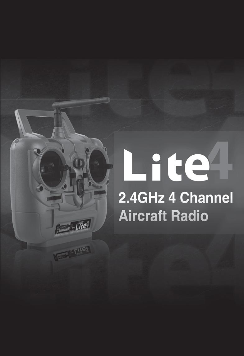
1 Instruction Manual
2 Introduction Thank you for purchasing the LITE4 2.4 digital proportional radio control system. LITE4 2.4 is easy to use and utilizes the latest in solid-state components for unsurpassed reliability and performance. It is important that you read and understand this manual before you attempt to operate your system. *NOTE : LITE4 2.4 is Compatible With all Minima Series Receivers. (Not Compatible With Optima Series Receivers) Table of Contents Page 2. Page 3. Page 4. Page 5. Page 6. Page 7. Page 8. Page 10. Page 11. Page 12. Page 13. Page 14. Page 15. Introduction Table of Contents 1. Transmitter A. Features B. Layout C. Specifications D. Servo Reversing E. Control Stick Adjustment F. Stick Lever Tension Adjustment G. Trim Levers H. Reading the LED Battery Indicator 2. Battery Installation 3. Operation A. Connection Diagrams B. Equipment Mounting C. Vibration and Water D. Antenna Installation (Minima 6S) E. Operating with a Trainer Cord 4. Set-up and Use of LITE4 2.4 A. ID-Set up A.K.A, Link or Bind B. SmartScan Function C. Range Check Function D. Min. and Max. Range for Binding E. Receiver-Servo Connection List F. Trim Adjustment G. ELVN (Elevon Mix) H. S. (Servo Reverse) I. V.TAIL (V-Tail) 5. Precautions 6. Mode Change 7. Service & Support 2
3 1. TRANSMITTER A. Features - Ergonomically designed 4 channel 2.4GHz(AFHSS) transmitter. - High quality precision gimbals with adjustable stick length and tension. - Servo reversing on all channels. - V-tail and Elevon Mixing - Trainer system. (Slave mode only) - Dry battery pack for 4cells for Alkaline battery - Easy to read 1 LED battery indicators. - SIC (Simulator Interface Cable) Compatible B. Layout FRONT Transmitter antenna Throttle/Rudder stick in MODE II Handle Neck-strap connector Aileron/ Elevator stick in MODE II Throttle trim Elevator trim Rudder trim Power switch Aileron trim LED indicator Link V-TAIL 2.4GHz 4 Channel Aircraft Radio LINK Button "LINK" button and LED Indicator Link (Servo Reverse) slide switch V-TAIL 2.4GHz 4 Channel Aircraft Radio (Mixing V-TAIL and ) slide switch The Link button can be used for the Link (ID setting) process between the LITE radio and Hitec minima receiver, entering the power down mode for range check, activating SmartScan function. The LED indicator shows current working status of the radio with red lights. For more detailed information, please read pages 10 and 11. "Mixing ( V-TAIL and )" slide switch The Mixing switch is used for mixing the function of servos with different wing types. ( V-TAIL and ) " (Servo Reverse) slide switch The switch is used for reversing the direction of the servos. "Low Battery Warning When the transmitter battery power descends to 4.4v or lower, Red color LED will be blinking. 3
4 C. Specifications - Power supply : 6V 4cell Dry battery - Current drain : 100mA - Output power : 100mw - Modulation : 2.4G AFHSS Single Directional D. Servo Reversing - LITE4 2.4 transmitter is equipped with servo reversing on all channels. - If you need to change travel direction of rotation, open the battery case and move the servo reversing switch. E. Control Stick Adjustment - The length of the non-slip control sticks can be adjusted to suit the requirements of the user. A B F. Stick Lever Tension Adjustment - The unique open-stick assembly provides fully adjustable stick tension to adjust the feel of the sticks in your hands. - You may adjust the stick tension of your sticks to provide the feel that you like for flying. To adjust your springs, you'll have to remove the rear case of the transmitter. Using a screwdriver, remove the six screws that hold the transmitter's rear cover into position, and put them in a safe place. Gently ease off the transmitter's rear cover and move it to the under side of the transmitter, carefully turning it as you would turn the page of a book. Now you'll see the view shown in the illustration. Using a small Philips screwdriver, rotate the adjusting screw for each stick for the desired spring tension. The tension increases when the adjusting screw is turned clockwise, and decreases for counterclockwise motion. When you are satisfied with the spring tensions, you may close the transmitter. Very carefully reinstall the rear cover. When the cover is properly in place, tighten the six screws. Tension adjusting screw LITE4 2.4 Lever Tension 4
5 G. Trim Levers - The trim levers associated with each control stick are used to correct or (trim-out) the tracking of the aircraft. - (Caution) Make sure the trims will move the surface past neutral when moved to their extremes. This will assure you have adequate trim control. - After your plane's first test flight, note the positions of the control surfaces that required trim. Next, center the trims and turn the receiver off. Now adjust the control linkage on the plane so the surfaces are in the same position before the trim levers were re-centered. - Turn on the radio and receiver and recheck the control surfaces to ensure that all the corrections were applied in the proper direction. H. Reading the LED Battery Indicator -There is one indicator lights on the face of the radio marked High and Low (blinking). -These relate to the condition of your transmitter battery and the other setups. Please pay attention to these LED lights and stop flying when the LED light is blinking. 2. BATTERY INSTALLATION - The transmitter requires four and the receiver battery pack needs four AA size batteries. These can be Alkaline cells - When loading the batteries, make sure the receiver and transmitter switches are in the "off" position. - Open the battery door in the back of the transmitter by pressing the tab on the bottom of the battery door and lifting up. - Load batteries into the appropriate slots, taking care to install according to the proper polarity. - Replace the battery door and turn the power "on". BATTERY COVER TO OPEN THE BATTERY COVER OF THE LITE4 2.4 YOU NEED TO PRESS THIS AND PUSH IT DOWNWARD. 4 AA SIZE BATTERY.BE CAREFUL TO LOAD RIGHT DIRECTION OF BATTERIES (+ -) 5
6 3. Operation A. Connection Diagrams Glow, Gas, Nitro or Electric-Powered Aircraft Using a Separate Receiver Battery. Follow this connection diagram when using a dedicated 4.8 to 6.0V NiMH battery pack. Warning : Verify your servos are rated for use with higher voltage(7.4v) batteries or a regulator. 2.4GHz 6 Channel Aircraft Receiver 2.4GHz 6 Channel Aircraft Receiver Optional BEC shown in diagram. It is recommended to use a large capacity BEC when a number of high torque servos are used and power requirements exceed that which the ESC provides. 6
7 B. Equipment Mounting Mounting When you mount each servo, use the supplied rubber grommets and insert an eyelet up through the bottom. Be sure not to over tighten the screws. If any portion of the servo case directly contacts the fuselage or the servo rails, the rubber grommets will not be able to attenuate vibration, which can lead to mechanical wear and possible servo failure. Servo Throw Once you have installed the servos, operate each one over its full travel and check that the pushrod and output arms do not bind or collide with each other, even at extreme trim settings. Check to see that each control linkage does not require undue force to move (if you hear a servo buzzing when there is no transmitter control motion, most likely there is too much friction in the control or pushrod). Even though the servo will tolerate loads like this, they will drain the battery pack much more rapidly. 90 Pushrod Factory Repair Service Information Please read the warranty card supplied with your system and return it. Before you decide to have your system repaired, if there is no apparent physical damage, read this instruction manual again and check to be sure that you are operating the system as it was designed to be operated. If you are still having trouble, pack up your system in its original shipping materials and send it to the nearest authorized Hitec R/C Service Center. Be sure to include a note in your package that describes the trouble in as much detail as possible, including: symptoms of the problem in as much detail as you can provide, including any unusual mounting conditions or equipment orientation, a list of items you are sending, and what you want to be repaired. Make sure you also provide your name, address and telephone number. C. Vibration and Water (OPTIMA & MINIMA Series) Vibration and Water The receiver contains precision electronic parts. Be sure to avoid vibration, shock, and temperature extremes. For protection, wrap the receiver in the "Flight Preserver" foam rubber, or use some other vibration-absorbing materials. If you are flying near bodies of water, it's also a good idea to protect the receiver by placing it in a plastic bag and securing the open end of the bag with a rubber band before wrapping it with foam. If you accidentally get moisture inside the receiver, you may experience intermittent operation or a possible crash. or 2.4GHz 6 Channel Aircraft Receiver or Cyanoacrylate Sponge Pad Switch Harness Installation When you are ready to install the receiver's switch harness, remove the switch cover and use it as a template to cut screw holes and a rectangular hole slightly larger than the full stroke of the switch. Choose a switch location on the opposite side of the fuselage from the engine exhaust, and choose a location where it can't be inadvertently turned on or off during handling or storage. Install the switch so that it moves without restriction and "snaps" from ON to and vice versa. 7
8 D. Antenna Installation (MINIMA 6S) The Minima 6S antenna system is made for high directivity consisting of two antennas. In order to maximize the functions of the Minimas, please install as shown below. TX RX TX 90 Recommended installation method to optimize receiver performance TX TX NOTE *Detailed range check mothod can be found on page 19. During the range check period, you should be able to walk away at least 75 feet from the model without losing control or seeing "jitter" in the servos. The range check should be done with the motor running and the model should be securely restrained in case of loss of control. Warnings Never pinch or bend the antenna, such behavior will cause serious damage to the antenna. Changing the length of the antenna reduces range. Never cut the antenna, such behavior will seriously reduce the reception range. E. Operating with a Trainer Cord When used as a student radio, the LITE4 2.4 supports the trainer system. Instructions below provide general information about the trainer system and which method may work for you. NOTE: 1. WHEN USING THE TRAINER SYSTEM IN THE STEREO JACK TO STEREO JACK FORMAT AS NOTED IN THE NEXT SEVERAL PARAGRAPHS, BOTH TRANSMITTERS ARE GOING TO TRANSMIT. 2. IF THE STUDENT TRANSMITTER HAS A REMOVABLE MODULE, REMOVE IT. THEN, IT WILL NOT BE TRANSMITTING. OTHERWISE, IF YOU ARE FLYING AT A CLUB FIELD USING FREQUENCY CONTROL, BE SURE YOU HAVE THE OK TO USE BOTH FREQUENCIES. 3. IF THERE IS NO REMOVABLE MODULE ON THE STUDENT TRANSMITTER, BOTH TRANSMITTERS MUST BE ON DIFFERENT FREQUENCIES. 1. To use the trainer system between STEREO Jack Transmitter and STEREO Jack Transmitter (Needs #58320 between 6-cell and 4 cellbattery radios). 1) Set up both the student's and instructor's transmitter to have identical trim and control motions. If the instructor's transmitter is on a different frequency than the student's, use the student's transmitter as the master transmitter, and the other transmitter as the student's. 2) Turn on the instructor's transmitter and DO NOT turn on the student's transmitter power. Plug Trainer Cord (#58320 Stereo Jack) accordingly into each transmitter. The trainer jack is on the back of the transmitter. 3) Move the controls on the instructor's transmitter, and verify each control moves the proper direction. Now verify that the student's trims and control travels match the instructor's by switching the trainer button on and off while leaving the control sticks and trims alone then move the control sticks. 4) The instructor's transmitter has normal control over the model unless the trainer button is pressed, passing control to the student's transmitter. If the student loses control, the instructor can quickly "take over" by releasing the trainer button and then controlling the model. 8
9 2. To use the trainer system between a STEREO Jack Transmitter and a DIN Jack Transmitter. (Needs trainer cable package #58321 between 6-cell battery radio and 8-cell battery radio systems). Please read the following instructions carefully for using transmitters with DIN Jack and/or stereo jack for the trainer system. You will need the Trainer cable full package (#58321). This full package consists of a STEREO Jack trainer cable(#58320), Instructor DIN Jack and Student DIN Jack Adapter. This package allows the proper connection between a 6-cell battery system radio (ex. Optic 5 2.4, Optic 6 Sport 2.4, Aurora 9) and 8-cell battery system radio (ex. Optic / Eclipse 7 2.4). NOTE This section tells you how to connect the transmitters only. Please read the prior sections for the full information needed to properly operate the trainer cable system. 3. To use the trainer system between the Transmitter having a STEREO jack as INSTRUCTOR and Transmitter having DIN jack as STUDENT. 1) Power on the INSTRUCTORS Transmitter having the STEREO Jack. 2) Plug the STEREO Jack trainer cable (#58320) into the Master, or INSTRUCTOR S transmitter. Note you will see "MAS MODE" on the LCD screen which means the transmitter is recognized as the INSTRUCTOR or "Master". 3) Connect the DIN Jack adapter marked "STUDENT" from the cable package #58320 to the other end of the stereo connector cable. This combination enables you to connect the cable to the STUDENT transmitter with a DIN Jack connector. 4) Plug the DIN connector into the socket on the STUDENT transmitter. 5) Finally, power on the STUDENT transmitter. Though it is powered on, the STUDENT transmitter will not transmit the radio signal as long as the trainer cable is connected properly. 4. To use the trainer system between the Transmitter having a DIN jack as INSTRUCTOR and a Transmitter having a STEREO jack as STUDENT. 1) Connect the INSTRUCTOR or DIN Jack adapter marker "Master" with #58320 stereo jack Trainer cable. 2) Power on the INSTRUCTOR transmitter. 3) Plug the combined trainer cable into the INSTRUCTOR transmitter DIN jack connection. 4) The STUDENT transmitter should be turned off. 5) Plug the trainer cable into the STUDENT transmitter with the stereo jack. The power to the STUDENT transmitter will turn on automatically (OPTIC has no LCD screen and SLV MODE only) 6) Though the STUDENT transmitter is powered on automatically, it will not transmit a radio signal as long as the trainer cable is connected properly. NOTE 1) Do NOT turn on the power of the STUDENT transmitter having the STEREO Jack. Once you plug the trainer cable into the STUDENT Transmitter using the STEREO Jack, it will be powered on automatically. 2) All Transmitters in the trainer system use their own batteries. Both batteries in both the Instructor and Student Transmitters should be properly charged and installed when flying in the trainer mode. 3) You may wish to use a simple "contractors cord" knot on the cable to connect the adapter and to keep it from coming "unplugged" when using it. Heat shrink tubing or electrical tape can also be used. 9
10 Link V-TAIL 2.4GHz 4 Channel Aircraft Radio Link V-TAIL 2.4GHz 4 Channel Aircraft Radio LITE4 2.4 Instruction Manual 4. Set-up and Use of the LITE4 2.4 To turn the system on and off, use the following sequence at all times. Turning On -Turn on the transmitter, then turn on the receiver. Turning Off -Turn off the receiver, then turn off the transmitter. A. ID-Setup A.K.A, Link or Bind Non-telemetry RXs (MINIMA & MICRO Series) Press and hold the button on the module, and turn on the transmitter. Release the link button. Link V-TAIL 2.4GHz 4 Ch Link V-TAIL 2.4GHz 4 Channel Aircraft Radio Link V-TAIL 2.4GHz 4 Ch Check if RED LED is blinking. press the link button for 2 sec. LED RED Press and hold the link button on Receiver and turn on the power. 2.4GHz 6 Channel Aircraft Receiver BLUE LEDs will blink rapidly to find the transmitter signal. Release the link button when BLUE LED on receiver glows steady. 2.4GHz 6 Channel Aircraft Receiver To save the setting, please reboot both transmitter and receiver. 8 When the link is completed, RED LED on the module will blink. LED RED When they are turned on again, RED LED on the module(or radio) and BLUE LED on the receiver will glow steady. 6 Channel Receiver 10
11 LITE4 2.4 Instruction Manual B. SmartScan Function Turn on the transmitter with pressing and holding the LINK button on the LITE4 2.4 for about 5sec. When RED LED is blinking rapidly, release the Link button. The LITE4 2.4 will automatically scan the frequency to find the cleanest and the most stable frequency in any area. When the scan is completed, the RED LED on the module stops blinking. Re-boot the transmitter (turn Off and On) and follow the link process with your receiver. Link V-TAIL N ELE Push 2Sec. LED RED & 2.4GHz 4 Ch Link V-TAIL 2.4GHz 4 Channel Aircraft Radio NOTE After Scanning, you need to do the link process again for all your receivers as receivers need new frequency hopping codes from the LITE4 2.4 C. Range Check Function It is critical that before each flight session you perform a range check that confirms the signal between the receiver and transmitter is appropriate. Unlike the FM/PPM or PCM signal radios, 2.4GHz systems use a fixed shorter, stubby transmitter antenna so the traditional method of range checking your system by lowering the transmitter antenna will not work. We instead use a power-down mode to reduce the transmitter signal strength. Once the power-down mode is activated when LINK button is pressed, shortening the effective range 100 feet (30 m). During this power-down mode, you should walk away from the secured aircraft, carrying the transmitter to a distance of approx. 30 meters in order to test the effective range. When release LINK button, power-down mode is finished and return to normal range mode. 11
12 LITE4 2.4 Instruction Manual D. Min. and Max. Range for Binding 5M(15ft) 50Cm(18in) Link V-TAIL 2.4GHz 4 Channel Aircraft Radio MIN RANGE MAX RANGE - Binding must be done within 15ft. (5m) of the transmitter and receiver. - The Transmitter and receiver need to be at least 18in. (45cm) from each other to bind properly. E. Receiver-Servo Connection List Receiver-Servo Connection List W/ LITE4 2.4 The table below shows where the aircraft's servos should plug into a receiver. Note that some functions shown will not operate until they are activated in the transmitter. The standard function is listed first for each channel. RX CH ACRO(Normal) ACRO(Elevon) ACRO(V-Tail) 12
13 F. Trim Adjustment This is a function for setting the trim values for each of the servos, allowing you to make adjustments to each individual servo independently of the trim switches located near the control stick of the radio (which can be adjusted in flight). We recommend that you first set up the model's servo pushrods so that the control surfaces are as centered as possible mechanically before attempting to adjust them in the trim switch. We also recommend that you try to keep all the trim values at the center position. If the values are skewed to once side, the servo's full range of travel may be restricted. Trim Switch G. ELVN (Elevon Mix) ELVN (Elevon mix) CH1 CH2 Aileron Operation Elevator Operation Front view H3 CH4 V-TAIL 2.4GHz 4 Ch If you are setting up a tail-less delta or flying wing aircraft, you can use this program to activate the pre-programmed elevon mix that mixes the output on the CH 1 aileron and CH 2 elevator servo channels. As you will notice in the servo connection chart, you plug one aileron servo in the receiver's channel 1 slot and the other aileron servo into channel 2-the slot that usually feeds the elevator. This is necessary because on these wing types, the ailerons must double as elevators. NOTE: When you activate ELVN, note that the V-tail mixing is rendered unavailable by the radio. When you change the function of ELVN to V.TAIL or V.TAIL to ELVN, Please TURN THE TRANSMITTER FIRST and then change the function. If you change the ELVN and V-TAIL functions when the transmitter is ON, nothing will be changed. CH4 Setting Up Elevons 1) Activate the elevon function by pushing the pre-programmed switch to the left. Now check your model to see what happens when you move the right-hand joystick side to-side. The ailerons should go up and down appropriately. Move the joystick forward and back to see if the ailerons both respond correctly as elevators. If necessary, use the function to reverse an offending servo. 2) Now set the amount (and direction if necessary as noted above) of each servo-both as ailerons and as elevators. Because flying wings are extraordinarily pitch sensitive (because the elevator control surface is so close to the airframe's center of gravity), you generally need the elevator travel and adjust horn linkage hole to be much less than that of the ailerons. 13
14 H. S. (Servo Reverse) S. (Servo Reverse) When you first turn on your model, you will immediately see whether all the control surfaces are moving in the correct direction when you wiggle the controls. If any are moving in reverse, you can come to this screen to reverse the throw of the offending servo. Normal Reversed Link V-TAIL 2.4GHz Reversing a Servo Let's say your elevator is going down when you pull back on the joystick, that is definitely not going to be a good situation when you go to fly your plane! To reverse the elevator servo, come to the switch in front of the radio s front panel. You'll notice that the symbol and, move the switch either or to make the servo operate in the proper direction. I. V.TAIL (V-Tail) V.TAIL (V-Tail) This is another built-in mixing program available on the LITE4 2.4 that mixes the rudder and elevator servos for controlling V-tailed aircraft. Similar to elevon programming, the two surfaces can move up and down together (for elevator control) or opposite (for rudder control in this case). CH2 CH4 CH2 CH4 Up Elevator Right Rudder (view from rear) H3 CH4 Surfaces can move up and down together (for elevator control) or opposite (for rudder control in this case). V-TAIL 2.4GHz 4 Ch NOTE: When you select V.TAIL, the ELVN program is rendered unavailable. When you change the function of ELVN to V.TAIL or V.TAIL to ELVN, Please TURN THE TRANSMITTER FIRST and then change the function. If you change the ELVN and V-TAIL functions when the transmitter is ON, nothing will be changed. Setting Up a V-Tail 1) Activate the function by pushing the pre-programmed switch to the right. 2) With your model turned on, check your servo travel directions (both rudder and elevator channels) to be sure they are correct. Use the switch if necessary to make the correction. 14
15 5. Precautions - Always turn your transmitter on first and off last. - Never fly your airplane without first performing a proper range check. - FCC regulation in the USA prohibits consumers from changing the crystal in the transmitter. For channel changes send your system to an authorized service/repair center. - Never fly around or over houses, people or power lines. - Always charge your batteries before you fly. - Always fly responsibly and respect the rights of others. - Make sure your frequency is clear before turning on your system. 6. Mode Change The mode can be changed by distributor in your country if you wish to change the mode. (mode 1 and2) It is not allowed to change the mode by yourself at your discretion. 7. Service & Support Hitec Customer Service Help is available from Hitec customer service through phone support and inquiries. Our US office is generally open Monday thru Friday, 8:00AM to 4:30PM PST. These hours and days may vary by season. Every attempt is made to answer all incoming service calls. Should you get our voice mail, leave your name and number and a staff member will return your call. Hitec Website Make plans to visit the Hitec website, on a regular basis. Not only is it full of specs and other information about the entire Hitec product line, our FAQ pages will eventually hold valuable information and updates regarding about the Spectra 2.4 module and Optima series of receivers. The On-Line Community One of the benefits of the extensive R/C online community is the vast wealth of archived knowledge available. Hitec sponsors forums on most of the popular R/C websites where a Hitec staff member or representative tries to answer all manner of product related questions. Bringing together strangers with common interests is proving to be one of the greatest gifts of the internet. If past history is any guide to the future, we are certain forums will be started about the Hitec 2.4GHz system and several are certain to stand out as valuable archives of information. Warranty and Non-Warranty Service All Hitec products carry a two year from date-of-purchase warranty against manufacturer's defects. Our trained and professional service representative will determine if the item will be repaired or replaced. To provide all the necessary information we need to administrate your repair, visit our website at and download the repair form, fill it out and send in your item for repair. Hitec Service Paine St. Poway CA service@hitecrcd.com 15


16 openings and cause erratic operation or loss of control. If you must fly in wet weather during a contest, be sure to protect your transmitter with a plastic bag or waterproof barrier.
17 FCC Information to User This equipment has been tested and found to comply with the limits for a Class B digital device, pursuant to Part 15 of the FCC Rules. These limits are designed to provide reasonable protection against harmful interference in a residential installation. This equipment generates, uses and can radiate radio frequency energy and, if not installed and used in accordance with the instructions, may cause harmful interference to radio communications. However, there is no guarantee that interference will not occur in a particular installation. If this equipment does cause harmful interference to radio or television reception, which can be determined by turning the equipment off and on, the user is encouraged to try to correct the interference by one of the following measures: Reorient or relocate the receiving antenna. Increase the separation between the equipment and receiver. Connect the equipment into an outlet on a circuit different from that to which the receiver is con-nected. Consult the dealer or an experienced radio/tv technician for help. Caution Modifications not expressly approved by the party responsible for compliance could void the user s authority to operate the equipment. FCC Compliance Information : This device complies with Part 15 of the FCC Rules. Operation is subject to the following two conditions: (1) This device may not cause harmful interference, and (2) this device must accept any interference received, including interference that may cause undesired operation IMPORTANT NOTE: FCC RF Radiation Exposure Statement: This equipment complies with FCC RF radiation exposure limits set forth for an uncontrolled environment. This equipment should be installed and operated with a minimum distance of 20 centimeters between the radiator and your body.this transmitter must not be co-located or operating in conjunction with any other antenna or transmitter.
 Keep these instructions. 3) Heed all warnings.")
 Do not using near any heat sources such as radiators, heat resisters,")
18 IMPORTANT Safety Instruction: 1) Read these instructions. 2) Keep these instructions. 3) Heed all warnings. 4) Follow all instructions. 5) Do not use this equipment near water. 6) Do not using near any heat sources such as radiators, heat resisters, stove, or other equipment that produce heat.
19 CONTACT INFORMATION Manufacturer Address : Lot 6 and 8, Blk. 24, Phase 4 CEPZ, Rosario, Cavite, Philippines To locate in-country Hitec RCD KOREA, INC. distributors of the LITE4 please refer to the Hitec RCD KOREA, INC. Website These distributor(s) represent local contacts for this product. CORPORATE HEADQUARTERS: Hitec RCD KOREA, INC. 653, YangCheong-Ri, Ochang-Eup, CheongWon-Gun, Chung Buk Province, Korea Tel: Fax: Web: This device complies with Industry Canada license-exempt RSS standard(s). Operation is Subject to the following two condition: (1) this device may not cause interference, and (2) this device must accept any interference, including interference that may cause undesired operation of the device.
20 EUROPEAN UNION DECLARATION OF CONFORMITY DECLARATION OF CONFORMITY Hitec RCD KOREA, INC. 653, YangCheong-Ri, Ochang-Eup, CheongWon-Gun, Chung Buk Province, Korea declare under our sole responsibility that the product(s) 2.4GHz Radio Control System LITE4 to which this declaration relate(s) is in conformance with the following standards: EN V1.8.1:2008 EN V2.1.1 :2009 EN :2006 EN V1.7.1:2006 following the provisions of the 1999/5/EC Directives.
21 2.4GHz 4 Channel Aircraft Radio Congratulations again and have fun!
Table of Contents Introduction/ Table of contents.. System Specifications Transmitter
 Introduction Thank you for purchasing the Hitec Laser digital proportional radio control system. The Laser is loaded with features, easy to use and utilizes the latest in solid-state components for unsurpassed
TS6 2.4GHz 6CH Radio Control System. Instruction manual. No.8610
 TS6 2.4GHz 6CH Radio Control System Instruction manual No.8610 Introduction Congratulations on your purchase of the Innovator TS6 + advanced 6 Channel 2.4GHz spread spectrum radio control system. This
Xtreme Power Systems
 Xtreme Power Systems XtremeLink NANO RECEIVER Installation And Usage Manual XtremeLink is a registered trademark of Xtreme Power Systems, LLC. Firmware v 1.9 Manual v 1.9 Revision Date: November 11 th,
CCR24T CCR24R. User s Guide WIRELESS TRANSMITTER SYSTEM WARRANTY SERVICE CARD WARRANTY CARD
 WARRANTY SERVICE CARD WARRANTY CARD PRODUCT NAME Wireless Transceiver System PERIOD MODEL NAME CCR24GEN YEAR PURCHASE DATE.. 200_ From the date of WARRANTY PERIOD.. 200_ purchase. CUSTOMER S ADDRESS :
12V Victor 888 User Manual
 The Victor speed controllers are specifically engineered for robotic applications. The high current capacity, low voltage drop, and peak surge capacity make the Victor ideal for drive systems while its
Instruction Manual. 2.4 GHz DIGITAL PROPORTIONAL 9-CH RADIO CONTROL SYSTEM. No.8901 JC7405
 2.4 GHz DIGITAL PROPORTIONAL 9-CH RADIO CONTROL SYSTEM Instruction Manual No.8901 FCC ID: VEJ-COUGARGP3 thundertiger.com Manufactured / Hersteller : Thunder Tiger Corp.(Ningbo) 28 Jin-Feng Road, Liang
Fly-Dream 2.4GHz V3 Radio Control System
 Fly-Dream 2.4GHz V3 Radio Control System Thank you for purchasing our Fly-Dream 2.4GHz V3 Radio Control System. We are sure you will enjoy it. The following notes will guide you through the simple set
DXXX Series Servo Programming...9 Introduction...9 Connections HSB-9XXX Series Servo Programming...19 Introduction...19 Connections...
 DPC-11 Operation Manual Table of Contents Section 1 Introduction...2 Section 2 Installation...4 Software Installation...4 Driver Installastion...7 Section 3 Operation...9 D Series Servo Programming...9
DJT RC Transmitter Module 2.4 GHz Two-Way Series
 Manual Rev.0.1-5.05.201 2 made by David LABURTHE dlaburthe@free. fr DJT RC Transmitter Module 2.4 GHz Two-Way Series U S E R ' S G U I D E FrSky Electronic Co., Ltd - No. 1, Huize Road, Wuxi, 21 4081,
XD-V30 Digital Wireless System
 XD-V30 Digital Wireless System Pilot s Handbook Manuel de pilotage Pilotenhandbuch Pilotenhandboek Manual del Piloto 取扱説明書 See www.line6.com/manuals for Advance Guide 40-00-0286 Advanced Users Guide available
RADIOLINK T8FB (FHSS) INSTRUCTION MANUAL. 8CH remote control system
 INSTRUCTION MANUAL. 8CH remote control system") RADIOLINK T8FB (FHSS) INSTRUCTION MANUAL 8CH remote control system RADIOLINK ELETRONIC LIMITED Technical updates and additional programming examples available at: www. radiolink.com INTRODUCTION Thank
RADIOLINK T8FB (FHSS) INSTRUCTION MANUAL 8CH remote control system RADIOLINK ELETRONIC LIMITED Technical updates and additional programming examples available at: www. radiolink.com INTRODUCTION Thank
Focus Iris Manual Ver 1.1
 Focus Iris Manual Ver 1.1 Preston Cinema Systems 1659 Eleventh Street Santa Monica CA 90404 tel 310 453 1852 fax 310 453 5672 www.prestoncinema.com Table of Contents 1. Description 2. Operation 3. Specifications
Instruction Manual. for Media Monkey. 1
 TM TM Instruction Manual for Media Monkey www.audioaperemote.com 1 Congratulations on acquiring your fine Audio Ape product Let s dive right in, getting up and running is a snap. Here are the components:
Radio Micro Force Manual v1.1
 Radio Micro Force Manual v1.1 Preston Cinema Systems 1659 Eleventh Street Santa Monica CA 90404 tel 310-453-1852 fax 310-453-5672 www.prestoncinema.com Table of Contents 1. Description 2. Operation 3.
SP GHz Digital Wireless Speakers. User s Manual. Please read before using the equipment. Please visit for details.
 SP1390 2.4GHz Digital Wireless Speakers User s Manual Please read before using the equipment. Please visit www.promowide.com for details. INTRODUCTION This 2.4G digital wireless speakers system uses latest
EXMITTER -- Professional Remote Control Products Expert
 EXMITTER -- Professional Remote Control Products Expert WARNING The following terms are used throughout the product literature to indicate various levels of potential harm when operating this product.
User Manual. ProRF Encoder Transmitter & Receiver
 User Manual ProRF Encoder Transmitter & Receiver WARRANTY Accurate Technology, Inc. warrants the ProScale Systems against defective parts and workmanship for 1 year commencing from the date of original
Copyright Graupner/SJ GmbH. Manual. Vector Unit / Vector Unit Extreme 2 channel HoTT 2,4 GHz receiver/servo/speed controller unit No No.
 Copyright Graupner/SJ GmbH EN Manual Vector Unit / Vector Unit Extreme 2 channel HoTT 2,4 GHz receiver/servo/speed controller unit No. 34002 No. 34003 Index Introduction... 4 Service Center... 4 Intended
HY737 Walkie talkie for kids
 HY737 Walkie talkie for kids ANTENNA SWITCH, VOLUME KNOB RED STATUS LIGHT MIC SPEAKER WWW.THEIPAR.CC WILLIAMWANG18@OUTLOOK.COM FCC ID: 2AJEM-HY737 ANTENNA ANTENNA SWITCH, VOLUME KNOB BELT BUCKLE PUSH TO
RADIOLINK T8FB (FHSS) INSTRUCTION MANUAL. 8CH remote control system
 INSTRUCTION MANUAL. 8CH remote control system") RADIOLINK T8FB (FHSS) INSTRUCTION MANUAL 8CH remote control system RADIOLINK ELETRONIC LIMITED Technical updates and additional programming examples available at: www. radiolink.com INTRODUCTION Thank
RADIOLINK T8FB (FHSS) INSTRUCTION MANUAL 8CH remote control system RADIOLINK ELETRONIC LIMITED Technical updates and additional programming examples available at: www. radiolink.com INTRODUCTION Thank
 ON Ergonomic Pistol Grip Design 2 Channel AM Proportional System 2 Channel Servo Reversing Switches 2 LED Battery Status Indicator Nicad Battery Charging Jack MADE IN PHILIPPINES NOR REV NOR REV ON I.
Mini Hi-Fi Audio *MFL * SIMPLE MANUAL
 ENGLISH SIMPLE MANUAL Mini Hi-Fi Audio To view the instructions of advanced features, visit http://www.lg.com and then download Owner s Manual. Some of the content in this manual may differ from your unit.
Schlage Control Smart Locks
 Schlage Control Smart Locks with Engage technology User guide Schlage Control Smart Locks with Engage technology User Guide Contents 3 Warranty 4 Standard Operation 4 Operation from the Inside 4 Operation
Remote Control Outlets Operating Instructions
 Remote Control Outlets Operating Instructions - FOR INDOOR OR OUTDOOR USE - IMPORTANT SAFEGUARDS Signal Word Definitions NOTE: These are general definitions only; all may not pertain to the actual product
Active Transmitter Combiner 8:1 AC 3200-II. Instruction manual
 Active Transmitter Combiner 8:1 AC 3200-II Instruction manual Contents Contents Important safety instructions... 2 The AC 3200-II active transmitter combiner 8:1... 4 Delivery includes... 4 Connection
Digital Wireless Weather System
 Digital Wireless Weather System Thermometer, Hygrometer and Heat Index with Remote Sensor Leading the Way in Accuracy 1458 Instruction Manual C H CHANNEL Congratulations on your purchase of the Taylor
3PRKA. 3-channel, FHSS Radio control system for Car INSTRUCTION MANUAL 1M23N Digital Proportional R/C System
 3PRKA 3-channel, FHSS Radio control system for Car 1M23N25002 INSTRUCTION MANUAL R Digital Proportional R/C System Thank you for purchasing a Futaba FHSS 3PRKA 2.4GHz system. This system is based on the
RF (RADIO FREQUENCY) WIRELESS PENDANT
 WIRELESS PENDANT") NOTE: The following information is an addition to the Operation section in the lift system owner s manual. It describes the RF wireless pendant for your lift system. You must read the lift system owner
NOTE: The following information is an addition to the Operation section in the lift system owner s manual. It describes the RF wireless pendant for your lift system. You must read the lift system owner
Mini Hi-Fi System *MFL * SIMPLE MANUAL
 ENGLISH SIMPLE MANUAL Mini Hi-Fi System Please read this manual carefully before operating your set and retain it for future reference. To view the instructions of advanced features, visit http://www.lg.com
4YF-2.4GHz INSTRUCTION MANUAL for Futaba 4YF-2.4GHz
 4YF-2.4GHz INSTRUCTION MANUAL for Futaba 4YF-2.4GHz 4-channel, FHSS Radio control system for Airplanes Futaba Corporation Technical updates available at: http://www.futaba-rc.com Entire Contents Copyright
MPRF01 Wireless 5uA Inductive Proximity Sensor RF System
 System Description; The MPRF01 is a simple ready to use Wireless Inductive. No programming is required; just insert 2, (1.5V) AA batteries into the Transmitter module. The RF receiver module is connected
TM14-2.4G/R6014FS/R608FS Radio Control Instruction Manual
 TM14-2.4G/R6014FS/R608FS Radio Control Instruction Manual INTRODUCTION Thank you for purchasing a FutabaR digital proportional R/C system. In order for you to make the best use of your system and to use
Mini Hi-Fi Audio *MFL * SIMPLE MANUAL
 ENGLISH SIMPLE MANUAL Mini Hi-Fi Audio To view the instructions of advanced features, visit http://www.lg.com and then download Owner s Manual. Some of the content in this manual may differ from your unit.
S5-ADU. Front... 4 Rear... 4
 Trantec ANTENNA DISTRIBUTOR INSTRUCTION MANUAL S5-ADU Thank you for purchasing TRANTEC Antenna Distributor. Please carefully follow the instructions in this manual to ensure long, trouble-free use of your
On-Line Cardio Theater Wireless Digital Transmitter Installation and Instruction Manual
 On-Line Cardio Theater Wireless Digital Transmitter Installation and Instruction Manual Full installation instructions accompany your Cardio Theater equipment order. This On-Line version of our Installation/Instruction
Black Oak / Light Oak / Cherrywood Wireless Panel Speaker
 4015115/4015116/4015117 Black Oak / Light Oak / Cherrywood Wireless Panel Speaker With Infrared Remote Control USER GUIDE For use with: Introduction These 900 MHz stereo wireless speaker system uses the
OPERATING INSTRUCTION
 No. S1001 OPERATING INSTRUCTION Prior to use, please read this manual thoroughly. Keep this manual in a convenient place for quick and easy reference. Before Use Support and Service - Customer support
CRUX II/BTGPS USER GUIDE. Model:D1598
 CRUX II/BTGPS USER GUIDE Model:D1598 0 Federal Communication Commission Interference Statement This equipment has been tested and found to comply with the limits for a Class B digital device, pursuant
4YWD 4-channel, FHSS Radio control system for EP Car INSTRUCTION MANUAL 1M23N Digital Proportional R/C System
 4YWD 4-channel, FHSS Radio control system for EP Car INSTRUCTION MANUAL 1M23N28702 R Digital Proportional R/C System Thank you for purchasing a Futaba 4YWD FHSS 2.4GHz system. This system is based on the
METAL DETECTOR INSTRUCTION GUIDE
 METAL DETECTOR INSTRUCTION GUIDE SET UP STEP 1. STEP 2. Your NATIONAL GEOGRAPHIC detector requires no assembly or tools. Simply remove the detector from the box. Press down the red UNLOCK button on both
USER MANUAL Digital Wireless Gateway U9120-W4 (P/N: 44002G-01)
") USER MANUAL Digital Wireless Gateway U9120-W4 (P/N: 44002G-01) 19549P-82 (11-16) 2016 DAVID CLARK COMPANY INCORPORATED Cautions and Warnings READ AND SAVE THESE INSTRUCTIONS. Follow the instructions in
USER MANUAL Digital Wireless Gateway U9120-W4 (P/N: 44002G-01) 19549P-82 (11-16) 2016 DAVID CLARK COMPANY INCORPORATED Cautions and Warnings READ AND SAVE THESE INSTRUCTIONS. Follow the instructions in
EXMITTER -- Professional Remote Control Products Expert
 EXMITTER -- Professional Remote Control Products Expert WARNING The following terms are used throughout the product literature to indicate various levels of potential harm when operating this product.
KANEKA OLED Lighting Module SL (LE-01L, LE-02L, LE-03L, LE-01H, LE-02H, LE-03H) Instruction Manual
 Instruction Manual") KANEKA OLED Lighting Module SL (LE-01L, LE-02L, LE-03L, LE-01H, LE-02H, LE-03H) Instruction Manual Safety Information p. 2 1 Product Overview p. 6 2 Connections and Wiring (when dimming is required) p.
KANEKA OLED Lighting Module SL (LE-01L, LE-02L, LE-03L, LE-01H, LE-02H, LE-03H) Instruction Manual Safety Information p. 2 1 Product Overview p. 6 2 Connections and Wiring (when dimming is required) p.
USER MANUAL. Sens it SENS IT 2.4
 USER MANUAL www.sensit.io Sens it SENS IT 2.4 SUMMARY SAFETY INSTRUCTIONS 4 I. CONTENT OF THE PACK 4 II. PRESENTATION 5 III. HOW TO START 8 IV. TECHNICAL SPECIFICATIONS 9 V. WARNING STATEMENTS 10 VI. CREDITS
(Wireless Solution)
") Wireless Solution 21.9687.1860 (Wireless Solution) 21.9687.1861 (Lumen Radio) 21.9687.1862 (City Theatrical) Wireless DMX Receivers Installation & User s Manual For use with VL440 Spot, VL770 Spot, VL880
Wireless Solution 21.9687.1860 (Wireless Solution) 21.9687.1861 (Lumen Radio) 21.9687.1862 (City Theatrical) Wireless DMX Receivers Installation & User s Manual For use with VL440 Spot, VL770 Spot, VL880
900 MHz Digital Wireless Indoor/Outdoor Speakers
 4015007 900 MHz Digital Wireless Indoor/Outdoor Speakers User s Manual This 900 MHz digital hybrid wireless speaker system uses the latest wireless technology that enables you to enjoy music and TV sound
Copyright Graupner/SJ GmbH. Manual. mz-4 2 channel HoTT 2,4 GHz transmitter No. S1031
 Copyright Graupner/SJ GmbH EN Manual mz-4 2 channel HoTT 2,4 GHz transmitter No. S1031 Index Introduction... 4 Service Centre... 4 Intended use... 5 Package content... 5 Technical Data... 5 Symbols explication...
INSTRUCTION MANUAL LCS TX
 INSTRUCTION MANUAL LCS TX 4 Channel Transmitter LCS1 Single Channel Transmitter Cardio Theater Inc Service 1-800-776-6695 Sales 1-800-CARDIO-1 1 Introduction CONGRATULATIONS on your choice of this product
T14MZ Software Update Function Modification Contents (Version: 1.1.0, 1.2.0)
") T14MZ Software Update Function Modification Contents (Version: 1.1.0, 1.2.0) 1M23N14837 Hardware setting This function is for adjusting the sticks, switches and trim characteristics. [System menu] Swash
T14MZ Software Update Function Modification Contents (Version: 1.1.0, 1.2.0) 1M23N14837 Hardware setting This function is for adjusting the sticks, switches and trim characteristics. [System menu] Swash
Installation Instructions For Profile Series v.g1 Exit Device
 Installation Instructions For Profile Series v.g1 Exit Device A7757C Copyright 2004, 2008, Sargent Manufacturing Company, an ASSA ABLOY Group company. All rights reserved. Reproduction in whole or in part
Wireless TFT LCD Monitor
 Wireless TFT LCD Monitor Description Screen Ratio: 16 : 9 Resolution: 800*RGB*480 TV: PAL / NTCS Voltage: 10--28V Rated Capacity: 5W Brightness: 450cd/m2 Contrast: 450:1 Operate temperature: -20~65 Display
User s Manual. Magical Learn & Go. Disney Visit the Disney website at DisneyPrincess.com 2010 VTech Printed in China
 User s Manual Magical Learn & Go 4-7 Years Disney Visit the Disney website at DisneyPrincess.com 2010 VTech Printed in China 91-002484-001-000 INTRODUCTION Thank you for purchasing the VTech Magical Learn
Copyright Graupner/SJ GmbH. Manual. mz-4 2 channel HoTT 2,4 GHz transmitter No. S1031
 Copyright Graupner/SJ GmbH EN Manual mz-4 2 channel HoTT 2,4 GHz transmitter No. S1031 Index Introduction... 4 Service Centre... 4 Intended use... 5 Package content... 5 Technical Data... 5 Symbols Explication...
Installation and Operation Manual MSI. Multi-Sensor Interface Hub. Interface Module for all Sensors Network and Wireless CAUTION
 Installation and Operation Manual MSI Multi-Sensor Interface Hub Interface Module for all Sensors Network and Wireless CAUTION This equipment complies with the limits for a Class B digital device, pursuant
USER MANUAL Universal Gateway U9921-GUV (P/N: 40994G-01)
") USER MANUAL Universal Gateway U9921-GUV (P/N: 40994G-01) 2012 DAVID CLARK COMPANY INCORPORATED Cautions and Warnings READ AND SAVE THESE INSTRUCTIONS. Follow the instructions in this installation manual.
USER MANUAL Universal Gateway U9921-GUV (P/N: 40994G-01) 2012 DAVID CLARK COMPANY INCORPORATED Cautions and Warnings READ AND SAVE THESE INSTRUCTIONS. Follow the instructions in this installation manual.
2/3 CHANNELS FOR AIRCRAFT 2FR/3FR
 2/3 CHANNELS FOR AIRCRAFT 2FR/3FR 1M23N09002 Thank you for purchasing a Futaba SKYSPORT SS2/SS3. Before using your SKYSPORT SS2/SS3, read this manual carefully and use your R/C set safely. After reading
Alchemy Systems L.P. SISTEM Radio Frequency Remote Control(8015-2R) & receiver(8015-2b) User Guide. Version: 2.4. Prepared by: Carlos A Acosta
 & receiver(8015-2b) User Guide. Version: 2.4. Prepared by: Carlos A Acosta") Alchemy Systems L.P. 8015 Shoal Creek Blvd., Suite 100 Austin, TX 78757 tel: 512-637-5100 fax: 512-637-5168 www.alchemysystems.com Alchemy Systems L.P. SISTEM Radio Frequency Remote Control(8015-2R) &
Alchemy Systems L.P. 8015 Shoal Creek Blvd., Suite 100 Austin, TX 78757 tel: 512-637-5100 fax: 512-637-5168 www.alchemysystems.com Alchemy Systems L.P. SISTEM Radio Frequency Remote Control(8015-2R) &
4EX. FM radio control system for aircraft. Futaba Corporation. Technical updates available at: 1M23N15601
 4EX INSTRUCTION MANUAL for Futaba 4EX 4-channel, FM radio control system for aircraft Futaba Corporation Technical updates available at: http://www.futaba-rc.com Entire Contents Copyright 2005 1M23N15601
Multi-Channel In-Out Thermometer with Cable Free Sensor and RF Clock
 Multi-Channel In-Out Thermometer with Cable Free Sensor and RF Clock MAIN FEATURES: MAIN UNIT GB MODEL: RMR182 USER'S MANUAL INTRODUCTION Congratulations on your purchase of the RMR182 Multi- Channel In-Out
User s Manual. Twist & Learn Gorilla Pals VTech
 User s Manual Twist & Learn Gorilla Pals 2009 VTech 91-101800-000-000 INTRODUCTION Thank you for purchasing the VTech Jungle Gym Twist & Learn Gorilla Pals! The VTech Jungle Gym Twist & Learn Gorilla
S ENSORLINK INSTALLATION MANUAL
 S ENSORLINK INSTALLATION MANUAL The SensorLink Transmitter (#7610) and SensorLink Receiver (#7611) are designed to work with Davis Instruments Weather Monitor II and the Weather Wizard III to enable wireless
Bluetooth Sports Headphones
 Bluetooth Sports Headphones Model:4R0M FCC ID:S4L4R0M USER GUIDE Charging 1 2 Pairing 5 sec. 1 2 On / Off Volume up 3 sec. Next track Play / Pause 2 sec. Volume down Previous track 2 sec. Fitting R Wearing
STI REPEATER HOW THE PRODUCT WORKS BEFORE YOU START. Installation and Operation Manual. Model: STI-34109
 Installation and Operation Manual STI REPEATER Model: STI-34109 Thank you for purchasing this fine product. Your satisfaction is very important to us. Please read this manual carefully to get the most
Manual Unihan UPWL6580
 Manual Unihan UPWL6580 Federal Communications Commission Statement This device complies with FCC Rules Part 15. Operation is subject to the following i. This device may not cause harmful interference,
A-16D A-Net Distributor
 A-16D A-Net Distributor For use with the Personal Monitor Mixing System Information in this document is subject to change. All rights reserved. Copyright 2003 Aviom, Inc. Printed in USA Document Rev. 1.03
Sound n Lights. Monitor. with Dual Receivers. Model Number: 71624
 Sound n Lights Monitor with Dual Receivers Model Number: 71624 For proper setup and use, please read these instructions. Please keep this instruction sheet for future reference, as it contains important
THANK YOU! Crush Micro PiX. Thank you for choosing Orange. You are now a member of the Legendary British Guitar Amplifier owners club!
 THANK YOU! Thank you for choosing Orange. You are now a member of the Legendary British Guitar Amplifier owners club! Since 1968 when the company was founded, Orange has been a pioneering force in the
Wireless Outdoor/Indoor Rechargeable Speaker System. User's Manual
 Wireless Outdoor/Indoor Rechargeable Speaker System User's Manual Contents 2 Specifications 3 Product Features 4 Introduction 5 Setting up Setting Up the Transmitter Locating the Transmitter Charging
STI REPEATER. BEFORE YOU START Refer to this drawing to become familiar with all the parts. Installation and Operation Manual.
 Installation and Operation Manual STI REPEATER Model: STI-34109 Thank you for purchasing this fine product. Your satisfaction is very important to us. Please read this manual carefully to get the most
FOR AVLEX ONLY MT-24A. User Guide. 2.4 GHz Digital Stationary Transmitter
 2.4 GHz Digital Stationary Transmitter User Guide All rights reserved. MN 017/05 Do not copy or forward without prior approvals MIPRO. Specifications and design subject to change without notice. 2 CE5
802.11n, 2.4G 1T1R Wireless LAN PCI Express Half Mini Card
 802.11n, 2.4G 1T1R Wireless LAN PCI Express Half Mini Card WN6605LH Realtek RTL8191SE User s Manual Ben J. Chen 3/4/2010 Federal Communication Commission Interference Statement This equipment has been
Manual and User Guide
 Manual and User Guide TV Talker FM System Model WFM 260 Model WFM 270 Transmitter Model WFM TX260 Receiver Model WFM RX260 Receiver Model WFM RX270 MAN 151H 2011 Williams Sound, LLC Contents Page System
CONTENTS INTRODUCTION LAYOUT DIAGRAM FEATURES AND SPECS SETTING AND OPERATION. 1. Transmitter
 CONTENTS INTRODUCTION LAYOUT DIAGRAM FEATURES AND SPECS SETTING AND OPERATION 1. Transmitter Loading batteries Reading the LED battery indicators Recharging NiCad batteries Transmitter antenna Changing
ORiNOCO AP-4000MR-LR and AP-4900MR-LR Access Points Safety and Regulatory Compliance Information
 IMPORTANT! Visit http://support.proxim.com for the latest safety and regulatory compliance information for this product. ORiNOCO AP-4000MR-LR and AP-4900MR-LR Access Points Safety and Regulatory Compliance
THE HUBSAN X4 DESIRE
 Ages 14+ READ THE INSTRUCTION MANUAL CAREFULLY PLEASE VISIT WWW.HUBSAN TO UPGRADE THE HUBSAN X4 DESIRE ITEM NO.: H502E ARM/DISARM MOTORS, SEE PAGE 06 RTH FUNCTION, SEE PAGE 09 COMPASS CALIBRATION, SEE
User s Manual VTech All rights reserved Printed in China US
 User s Manual 2016 VTech All rights reserved Printed in China 91-003216-006 US Dear Parent, At VTech, we know how important the first day of school is for your child. To help prepare preschoolers for this
Remote Dog Training Collar. Shenzhen Trainertec Electronic Co., Ltd
 Remote Dog Training Collar Shenzhen Trainertec Electronic Co., Ltd Http://www.trainertec.com Remote Dog Trainer Operation Guide Thank you for choosing Trainertec, the best electronic training collar in
Visit TheNewInstant.com for additional information, including high-res images. Quick-Start Guide
 Visit TheNewInstant.com for additional information, including high-res images. Quick-Start Guide Table of Contents Introduction... 6 Polaroid PoGo Specifications... 8 ZINK Photo Paper Specifications...
User Manual Digital Wireless Rain Gauge
 Rain Gauge Specifications: User Manual Digital Wireless Rain Gauge - Outdoor rain gauge transmitter measures the rainfall and transmits the data to an indoor rain monitor base unit which shows the rainfall
System Requirements: D-Link Systems, Inc.
 System Requirements: Minimum System Requirements: CD-ROM Drive Computers with Windows, Macintosh, or Linux-based operating systems Installed Ether net Adapter Internet Explorer version 6.0 or Netscape
(6) Changing the brightness of the illumination. 16 (7) Additional features Power saving mode Checking the battery status...
 Changing the brightness of the illumination. 16 (7) Additional features Power saving mode Checking the battery status...") Table of Contents 1. What is the SenseView LIGHT?... 4 2. Safety precaution... 5 3. Package... 6 4. Configuration... 7 5. After purchasing... 9 (1) Charging... 9 (2) Remove screen protection film... 9
Table of Contents 1. What is the SenseView LIGHT?... 4 2. Safety precaution... 5 3. Package... 6 4. Configuration... 7 5. After purchasing... 9 (1) Charging... 9 (2) Remove screen protection film... 9
How to install your ecobee Switch+
 How to install your ecobee Switch+ Warning Installing this product involves handling high voltage wiring. Each step of the enclosed instructions must be followed carefully. To avoid fire, personal injury,
Warning: This product contains a chemical known to cause cancer and birth defects (or other reproductive harm).
.") Thank you for purchasing a Futaba SKYSPORT 4YBF. Before using your SKYSPORT 4YBF, read this manual carefully and use your R/C set safely. After reading this manual, store it in a safe place. See the glossary
Thank you for purchasing a Futaba SKYSPORT 4YBF. Before using your SKYSPORT 4YBF, read this manual carefully and use your R/C set safely. After reading this manual, store it in a safe place. See the glossary
Hi-Fi Shelf System *MFL * SIMPLE MANUAL
 ENGLISH SIMPLE MANUAL Hi-Fi Shelf System Please read this manual carefully before operating your set and retain it for future reference. To view the instructions of advanced features, visit http://www.lg.com
Users Manual AgCam /EnduraCam TM
 Users Manual AgCam /EnduraCam TM 2.4GHz Analog Wireless A/V Sender Part Number: RHPAIR RHTX & RHWPTX RHRX & RHES Contents: 1. Components... 2 1.1 Standard Kit... 2 1.2 Waterproof Transmitter... 3 1.3 Easy
x12 BATTERIES INCLUDED
 AGES 8+ 13744 x12 BATTERIES INCLUDED Replace with 12 x 1.5V AA or R6 size alkaline batteries. Phillips/cross head screwdriver (not included) needed to replace batteries. Standard, CRT TV only. Not for
Shields. Outdoor Shields Owner s Manual. Avoidance Solutions.
 Shields Avoidance Solutions Outdoor Shields Owner s Manual www.invisiblefence.com Important Precautions Invisible Fence Brand systems have protected over two million pets. However, there are some precautions
Sirius instruction manual
 Sirius instruction manual Thank you for purchasing the eagle wing plane.the sirius is designed for First-Person-Vision (FPV) application spec ifically. Due to the high wingand push prop design, the on-board
(Build Instructions)
") (Build Instructions) Specifications * Wingspan: 58cm * Length: 50cm * Flying Weight: 59 grams * Channels: 3 (Rudder Elevator Throttle) * Suggested Receiver: 4Ch Micro * Motor: 8mm GearDrive * Prop: GWS
(Build Instructions) Specifications * Wingspan: 58cm * Length: 50cm * Flying Weight: 59 grams * Channels: 3 (Rudder Elevator Throttle) * Suggested Receiver: 4Ch Micro * Motor: 8mm GearDrive * Prop: GWS
INSTALLATION MANUAL FOR SAL SERIES WIRELESS CLOCKS SPECIFICATIONS
 INSTALLATION MANUAL FOR SAL SERIES WIRELESS CLOCKS SPECIFICATIONS Time base: Quartz Power input: Battery (2 D cell) : Part # SAL-1BS-12R-0 95 135 VAC / 60 Hz: Part # SAL-1BS-12R-1 7 28 VAC / 60 Hz: Part
Wireless Rain Station
 Wireless Rain Station For online video support: http://bit.ly/laxtechtalk Instructional Manual Model: T84237 DC:102017 Table of Contents 1 Button Function Explanation 8 NOW Rainfall Alert (silent) 2 Setup
Learn & Go. User s Manual. c 2013 VTech Printed in China US
 Learn & Go User s Manual 2013 Viacom International Inc. All Rights Reserved. Nickelodeon, Nick Jr., Dora the Explorer and all related titles, logos and characters are trademarks of Viacom International
FinishLynx Interface. Includes: Power requirements: 9 VDC Power Adapter (included) Size: Approximately 5 x 3 x 2 Approximate weight: 5.57oz.
 Size: Approximately 5 x 3 x 2 Approximate weight: 5.57oz.") FinishLynx Interface Includes: FinishLynx Wired Interface Or 1 ea. FinishLynx Wireless Interface & MPCX Receiver FinishLynx CAPTION PLATE SET w/layout Diagram Power requirements: 9 VDC Power Adapter (included)
FinishLynx Interface Includes: FinishLynx Wired Interface Or 1 ea. FinishLynx Wireless Interface & MPCX Receiver FinishLynx CAPTION PLATE SET w/layout Diagram Power requirements: 9 VDC Power Adapter (included)
User manual AWR-8000 / AWR Advanced Wireless Communications
 User manual AWR-8000 / AWR-8001 Advanced Wireless Communications THANK YOU! Thank you for your purchase of Advanced Wireless Communications AWR-8000 / AWR-8001 two-way radio. This portable two-way radio
Technical Description. Wireless Automation Input/Output Module WDIO100
 Technical Description Wireless Automation Input/Output Module Please note the following Target group This description is intended for the use of trained specialists in electrical installation and control
Digital Portable Radio
 II TP620 Digital Portable Radio We are very grateful for your purchasing KIRISUN brand two-way radios produced by Kirisun Communications Co., Ltd. We believe KIRISUN two-way radio, which always incorporates
Super Switch Indoor Wireless Remote Control Wall Outlets
 Super Switch Indoor Wireless Remote Control Wall Outlets The Remote Control for Living Room, Kitchen & Bedroom Lights, Lamps, Fans and More Item/Art. 770742 Model #: SSW2-3-3322 Set of (3) Indoor Outlets
USER MANUAL Push Back Gateway U9920-GPB (P/N: 40993G-01)
") USER MANUAL Push Back Gateway U9920-GPB (P/N: 40993G-01) 2016 DAVID CLARK COMPANY INCORPORATED Cautions and Warnings READ AND SAVE THESE INSTRUCTIONS. Follow the instructions in this installation manual.
USER MANUAL Push Back Gateway U9920-GPB (P/N: 40993G-01) 2016 DAVID CLARK COMPANY INCORPORATED Cautions and Warnings READ AND SAVE THESE INSTRUCTIONS. Follow the instructions in this installation manual.
High performance 90mm fiberglass jet
 High performance 90mm fiberglass jet Assembly manual For intermediate and advanced fliers only! Specs Wingspan: 1255mm Fuselage length: 1250mm Flying weight: 2600-3000g Wing area: 22.6 dm² Wing loading:
Instruction Manual. Specification:
 Instruction Manual H I G Specification: Wingspan: 133 cm (52.3 inches) Length : 104 cm (40.9 inches) Weight : 1830gr Engine : 25-32 two stroke Radio : 4 channel - 4 servo H W I N G KIT CONTENTS: We have