Smart Wires. Distributed Series Reactance for Grid Power Flow Control. IEEE PES Chapter Meeting - Jackson, MS August 8, 2012
|
|
|
- Melanie Barker
- 6 years ago
- Views:
Transcription
1 Smart Wires Distributed Series Reactance for Grid Power Flow Control IEEE PES Chapter Meeting - Jackson, MS August 8, 2012 Jerry Melcher Director Program Management Smart Wires Inc.
2 2

3 Agenda Technology History Smart Wires Overview Initial System Impact Simulations Smart Wires Design Commercialization Timeline Wrap-Up 3
4 INTRODUCTION Solutions for Transmission Congestion/Reliability Traditional solutions, such as new lines, are expensive and subject to siting and ROW delays. New lines also deteriorate system utilization. Shunt VAR compensation provides voltage support but has limited ability to control power flows in the system. Technology solutions such as Flexible AC Transmission Systems (FACTS) are expensive and have been unable to meet utility expectations in terms of reliability and cost. Distributed control of line impedances offers a new approach for controlling power flow in networked systems, allowing higher reliability & utilization 4
5 TECHNOLOGY Technology History CEC sponsored the research program in 2006 TVA and DOE funded the development of a Smart Wires (DSR) prototype Georgia Tech NEETRAC initiated the Smart Wires Focus Initiative (SWFI) to work with utilities and the commercialization partner 5 members - Southern, TVA, BG&E, NRECA, Southwire SWFI Goals Re-designed for manufacture Lab tested Field testing in Q Smart Wire Grid, has worldwide exclusive license for the technology from Georgia Institute of Technology 5
6 TECHNOLOGY - CONTINUED Smart Wires Technology Overview Functions as a current limiter to divert current from the overloaded lines to underutilized ones Increases line impedance by injecting a pre-tuned value of magnetizing inductance of the Single-Turn Transformer Each module is triggered at a predefined set point to reflect a gradual increase in line impedance No communication required and the devices operate autonomously 6


7 CONGESTION EXAMPLE FROM TVA SERVICE AREA Interchange Congestion Areas 7
8 SIMULATION EXAMPLE -1 Simplified Four Bus System 8
9 Load 1 (MW) RESULTS Initial Results - 1 Max System Load with and without Smart Wires Increase in Transfer Capacity 160 Line 2,4 Overload Line 2,5 Overload Line 2 Overload Line 1,2,5 Overload Line 5 Overload Load 2 (MW) 9
10 Line Current (KA) RESULTS - CONTINUED Contingency Condition: Generator Outage 1 Profile of Line 2 Current A 624.2A A Generator Taken Off DSR Active Time (sec) 10
11 SIMULATION EXAMPLE BUS SYSTEM Baseline MW: G MW Increase in ATC possible: 638 MW Number of modules G G9 38 required: 45,000 Total Control effort: 16 G6 378 MVARs (8.4kVAR/module) 39 G G G5 34 G4 36 G7 G3 11

12 RESULTS Initial Results Increase in line utilization from 59% to 93.3% 12


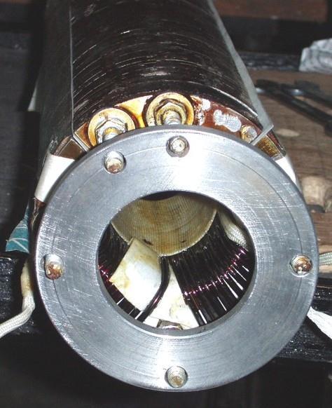
13 DSR Prototype GA Tech Case Design 13
14 DESIGN SPECIFICATIONS Initial and Current Design Specifications, Ratings Preliminary Alpha Prototype Spec Max weight : 150 lb. Conductor size: 336 to 1590 kcmil, Operating voltage level: kv Fault current: 63kA Life: 20+ year life w/o maintenance Install: Live line or outaged No corona at operating voltage Environmental: Resistant to salt fog, Aeolian vibration, ice buildup, thermal cycling Conductor impact: No mechanical or thermal conductor degradation Lightning Strike: tested to line BIL Wind loading: up to 150 mph, Communications: Module to ground or SCADA link Module rating 10 kva, 1000 A (50 µh per module) One DSR module per phase per mile changes line impedance (138 kv) by roughly 2% 14

15 ALPHA SMART WIRE DEVICE UNDER TEST CORONA TEST WITH 10 GROUND PLANE 15

16 SWG DEVICE TESTING CORONA TEST 16

17 Smart Wires Prototype Testing 17 ka Fault 17
18 PROTECTION Impact on Power System Protection Changing the impedance of the line can result in under reach of the distance relay By-pass of Smart Wires modules must be faster than the operating time of the protection algorithm Distance relays operate by decomposing voltage and current into fundamental components. Operating time can be around 1 cycle (16666 µs). Smart Wires modules are by-passed in about 40µs. An example is shown below where by-pass has been considered up to about 600 µs based on early DSR designs. 3φ fault Location Fault Level Fault Clearing Time - Nominal Conditions Fault Clearing Time - With DSR Modules Injecting 25% of line length 31,640 A 15.8 ms 16.2 ms 50% of line length A 10.3 ms 10.6 ms 75% of line length 50, 000 A 8.3 ms 8.9 ms 18
19 Market Study and Investments Evaluating available solutions for power flow control Solution Cost Limitation Transmission Lines $500,000/mile, Substation estimate $80M Mitigates congestion at one point Lumpy investment ROW and siting issues HVDC Transmission $500,000/mile, Converter Stations $250M Point to point solution (merchant lines) ROW and siting issues Sen Transformers $100/KVA* Low reliability due to fault modes Bulky solution Shunt FACTS $60-$120/KVAR Weak influence on active power flow control Lower reliability than grid Series FACTS $60-$160/KVAR+ Very high installation and operating costs Bulky solution Distributed Series Reactance $100/KVAR* Cannot reduce line impedance without communications 19
20 Smart Wires Topology - II 20
21 Summary DOE ARPA-E Awardee, contract Apr 2012 Pilot DSR manufacturing Jun 2012 Test bed installation planned at TVA - Q Others early 2013 Contact: Jerry Melcher Director Program Management Smart Wire Grid, Inc Clay Street Suite 840 Oakland, CA C F 21
Distributed Series Reactor An overview of the conductor impacts of the DSR
 1 Distributed Series Reactor An overview of the conductor impacts of the DSR Joseph Goldenburg, P.E. Mechanical Section Lead and Hardware Manager at NEETRAC 2 DSR Technology Overview History Table of Contents
Active Smart Wires: An Inverter-less Static Series Compensator. Prof. Deepak Divan Fellow
 Active Smart Wires: An Inverter-less Static Series Compensator Frank Kreikebaum Student Member Munuswamy Imayavaramban Member Prof. Deepak Divan Fellow Georgia Institute of Technology 777 Atlantic Dr NW,
THE power grid infrastructure in the U.S. is in urgent need
 IEEE TRANSACTIONS ON POWER ELECTRONICS, VOL. 22, NO. 6, NOVEMBER 2007 2253 Distributed FACTS A New Concept for Realizing Grid Power Flow Control Deepak Divan and Harjeet Johal Abstract Flexible ac Transmission
Line Impedance Estimation Using SCADA Data
 Line Impedance Estimation Using SCADA Data Presenter: Ramiro Da Corte - Power System Engineer Prepared by: James Shen - Principal Engineer, AESO Nov. 5, 214 Background AESO is responsible for grid reliability
The Many Uses of Transmission Line Arresters
 Introduction It was not realized at the time, but the 1992 introduction of the polymer-housed transmission line arrester (TLA) was clearly a game changer in the practice of lightning protection of transmission
CHAPTER 4 POWER QUALITY AND VAR COMPENSATION IN DISTRIBUTION SYSTEMS
 84 CHAPTER 4 POWER QUALITY AND VAR COMPENSATION IN DISTRIBUTION SYSTEMS 4.1 INTRODUCTION Now a days, the growth of digital economy implies a widespread use of electronic equipment not only in the industrial
ATC s Mackinac Back to Back. Summary
 ATC s Mackinac Back to Back HVDC Project Update Michael B. Marz American Transmission Company Summary The Need For Flow Control at Mackinac Mackinac Flow Control Requirements Available Flow Control Technologies
, ,54 A
 AEB5EN2 Ground fault Example Power line 22 kv has the partial capacity to the ground 4,3.0 F/km. Decide whether ground fault currents compensation is required if the line length is 30 km. We calculate
ECE 422/522 Power System Operations & Planning/Power Systems Analysis II 5 - Reactive Power and Voltage Control
 ECE 422/522 Power System Operations & Planning/Power Systems Analysis II 5 - Reactive Power and Voltage Control Spring 2014 Instructor: Kai Sun 1 References Saadat s Chapters 12.6 ~12.7 Kundur s Sections
Designing For a Critical Load using a Spot Network
 This is a photographic template your photograph should fit precisely within this rectangle. Designing For a Critical Load using a Spot Network Tony Oruga, P.E. Product and Sales Manager Network Protectors
Lab 1. Objectives. Single Line Diagram. Methodology. Observations. Jon Jawnsy Yu 26 October 2009
 Lab 1 Objectives In this lab, our objective is to simulate a simple single machine infinite bus configuration using the PowerWorld Simulator software. We design a local generator system (a synchronous
QUESTIONNAIRE for Wind Farm Power Stations only
 TRANSMISSION SYSTEM OPERATOR QUESTIONNAIRE for Wind Farm Power Stations only To be submitted by the Generation Licensees together with the Application for Connection Certificate according to IEC 61400-21
Dietrich Bonmann, ABB Monselice Transformer Days, May 5, 2010 Optimized AC transmission solutions with phase-shifting transformers and shunt reactors
 Dietrich Bonmann, ABB Monselice Transformer Days, May 5, 2010 Optimized AC transmission solutions with phase-shifting transformers and shunt reactors May 11, 2010 Slide 1 Why phase-shifting transformers
CONTENTS. 1. Introduction Generating Stations 9 40
 CONTENTS 1. Introduction 1 8 Importance of Electrical Energy Generation of Electrical Energy Sources of Energy Comparison of Energy Sources Units of Energy Relationship among Energy Units Efficiency Calorific
DISTRIBUTED SERIES REACTANCE: A NEW APPROACH TO REALIZE GRID POWER FLOW CONTROL
 DISTRIBUTED SERIES REACTANCE: A NEW APPROACH TO REALIZE GRID POWER FLOW CONTROL A Thesis Presented to The Academic Faculty by Harjeet Johal In Partial Fulfillment of the Requirements for the Degree Doctor
Jason Harchick, P.E. Sr. Manager, System Planning and Protection Ryan Young Manager, Substation Engineering
 DLC s Brady IIB Project Jason Harchick, P.E. Sr. Manager, System Planning and Protection Ryan Young Manager, Substation Engineering Project Need In 2007, PJM and Duquesne Light Company (DLC) transmission
Control Applications and Economic Evaluations of Distributed Series Reactors in Unbalanced Electrical Transmission Systems
 Control Applications and Economic Evaluations of Distributed Series Reactors in Unbalanced Electrical Transmission Systems By Shaimaa Abd Alla Omran Dissertation submitted to the faculty of the Virginia
Power Conditioning Equipment for Improvement of Power Quality in Distribution Systems M. Weinhold R. Zurowski T. Mangold L. Voss
 Power Conditioning Equipment for Improvement of Power Quality in Distribution Systems M. Weinhold R. Zurowski T. Mangold L. Voss Siemens AG, EV NP3 P.O. Box 3220 91050 Erlangen, Germany e-mail: Michael.Weinhold@erls04.siemens.de
POWER FACTOR CORRECTION. HARMONIC FILTERING. MEDIUM AND HIGH VOLTAGE SOLUTIONS.
 POWER FACTOR CORRECTION. HARMONIC FILTERING. MEDIUM AND HIGH VOLTAGE SOLUTIONS. This document may be subject to changes. Contact ARTECHE to confirm the characteristics and availability of the products
G. KOBET, I. GRANT, G. GOZA Tennessee Valley Authority USA. R. GIRGIS, M. ESPINDOLA ABB Corporation USA SUMMARY
 21, rue d Artois, F-75008 PARIS CIGRE US National Committee http : //www.cigre.org 2016 Grid of the Future Symposium Assessment of the Impact of GMD on the TVA 500 kv Grid & Power Transformers Part II:
ATC s Mackinac Back-to-Back HVDC Project: Planning and Operation Considerations for Michigan s Eastern Upper and Northern Lower Peninsulas
 21, rue d Artois, F-75008 PARIS CIGRE US National Committee http : //www.cigre.org 2013 Grid of the Future Symposium ATC s Mackinac Back-to-Back HVDC Project: Planning and Operation Considerations for
Notes 1: Introduction to Distribution Systems
 Notes 1: Introduction to Distribution Systems 1.0 Introduction Power systems are comprised of 3 basic electrical subsystems. Generation subsystem Transmission subsystem Distribution subsystem The subtransmission
Joe Warner, Electric Power Industry Conference (EPIC), November 15, 2016 Advances in Grid Equipment Transmission Shunt Compensation
, November 15, 2016 Advances in Grid Equipment Transmission Shunt Compensation") Joe Warner, Electric Power Industry Conference (EPIC), November 15, 2016 Advances in Grid Equipment Transmission Shunt Compensation Slide 1 Excerpt from the BoA BoA: Book of Acronyms MSC/MSR: Mechanically
Joe Warner, Electric Power Industry Conference (EPIC), November 15, 2016 Advances in Grid Equipment Transmission Shunt Compensation Slide 1 Excerpt from the BoA BoA: Book of Acronyms MSC/MSR: Mechanically
IDAHO PURPA GENERATOR INTERCONNECTION REQUEST (Application Form)
") IDAHO PURPA GENERATOR INTERCONNECTION REQUEST (Application Form) Transmission Provider: IDAHO POWER COMPANY Designated Contact Person: Jeremiah Creason Address: 1221 W. Idaho Street, Boise ID 83702 Telephone
IDAHO PURPA GENERATOR INTERCONNECTION REQUEST (Application Form) Transmission Provider: IDAHO POWER COMPANY Designated Contact Person: Jeremiah Creason Address: 1221 W. Idaho Street, Boise ID 83702 Telephone
1st Qua u r a ter e M e M e e t e in i g 2nd Qua u r a ter e M e M e e t e in i g
 2011 SERTP Welcome SERTP 2011 First RPSG Meeting & Interactive Training Session 9:00 AM 3:00 PM 1 2011 SERTP The SERTP process is a transmission planning process. Please contact the respective transmission
WIND FARM Flexible AC Transmission Systems
 WIND FARM Flexible AC Transmission Systems WIND ENERGY AND GRID INTEGRATION Madrid 24-25 January 2006 Jacques COURAULT Assumption: Wind farm is with Fixed Speed Induction Generator (FSIG) SUMMARY 1/ Wind
Wide Area Monitoring with Phasor Measurement Data
 Wide Area Monitoring with Phasor Measurement Data Dr. Markus Wache Siemens E D EA, Nuremberg, Germany Content Content Basics of Phasor Measurement Realization of PMUs Power System Stability Standard IEEE
ESB National Grid Transmission Planning Criteria
 ESB National Grid Transmission Planning Criteria 1 General Principles 1.1 Objective The specific function of transmission planning is to ensure the co-ordinated development of a reliable, efficient, and
COMPARATIVE PERFORMANCE OF SMART WIRES SMARTVALVE WITH EHV SERIES CAPACITOR: IMPLICATIONS FOR SUB-SYNCHRONOUS RESONANCE (SSR)
") 7 February 2018 RM Zavadil COMPARATIVE PERFORMANCE OF SMART WIRES SMARTVALVE WITH EHV SERIES CAPACITOR: IMPLICATIONS FOR SUB-SYNCHRONOUS RESONANCE (SSR) Brief Overview of Sub-Synchronous Resonance Series
7 February 2018 RM Zavadil COMPARATIVE PERFORMANCE OF SMART WIRES SMARTVALVE WITH EHV SERIES CAPACITOR: IMPLICATIONS FOR SUB-SYNCHRONOUS RESONANCE (SSR) Brief Overview of Sub-Synchronous Resonance Series
HVDC High Voltage Direct Current
 HVDC High Voltage Direct Current Typical HVDC Station BACK TO BACK CONVERTER STATION MONO POLAR WITH GROUND RETURN PA Back to Back Converters indicates that the Rectifiers & Inverters are located in the
Fault Locating at Pacific Gas and Electric Company
 Fault Locating at Pacific Gas and Electric Company i-pcgrid 2015 Scott Hayes Relay Targets were the earliest fault location devices. Light Beam Oscillographs and later Digital Fault Recorders Microprocessor
Dynamic Grid Edge Control
 Dynamic Grid Edge Control Visibility, Action & Analytics at the Grid Edge to Maximize Grid Modernization Benefits The existence of greater volatility at the grid edge creates a set of problems that require
Voltage Control with Distributed Generators to Enhance Voltage Stability
 Advanced Electricity Infrastructure Workshop Global Climate & Energy Project STANFORD UNIVERSITY, Nov. 1~2, 2007 Voltage Control with Distributed Generators to Enhance Voltage Stability Presenter: Fangxing
Constant Terminal Voltage. Working Group Meeting 4 19 th September 2014
 Constant Terminal Voltage Working Group Meeting 4 19 th September 014 Overview Options summary System under investigation Options analysis Discussion Options Option 1 Constant Terminal Voltage controlled
Integration of Wind Generation into Weak Grids
 Integration of Wind Generation into Weak Grids Jason MacDowell GE Energy Consulting NERC ERSTF Atlanta, GA December 10-11, 2014 Outline Conventional and Power Electronic (PE) Sources Stability limitations
EH2741 Communication and Control in Electric Power Systems Lecture 2
 KTH ROYAL INSTITUTE OF TECHNOLOGY EH2741 Communication and Control in Electric Power Systems Lecture 2 Lars Nordström larsno@kth.se Course map Outline Transmission Grids vs Distribution grids Primary Equipment
GridLiance Reliability Criteria
 GridLiance Reliability Criteria Planning Department March 1, 2018 FOREWORD The GridLiance system is planned, designed, constructed, and operated to assure continuity of service during system disturbances
Coil Products Beginnings 1960 State of the Art. Customer partnership around the globe. Continuous innovation since 1900
 Coil Products Coil Products Customer partnership around the globe More than 250,000 coil products delivered to more than 170 countries. More than 60 years of operational experience. 35,000 in Europe 13,000
Induction Machine Test Case for the 34-Bus Test Feeder -Distribution Feeders Steady State and Dynamic Solutions
 Induction Machine Test Case for the 34-Bus Test Feeder -Distribution Feeders Steady State and Dynamic Solutions Induction Machine Modeling for Distribution System Analysis panel IEEE PES General Meeting
Connection Impact Assessment Application
 Connection Impact Assessment Application This form is for generators applying for Connection Impact Assessment (CIA) and for generators with a project size >10 kw. Please return the completed form by email,
Application of SVCs to Satisfy Reactive Power Needs of Power Systems
 1 Application of SVCs to Satisfy Reactive Power Needs of Power Systems H. K. Tyll, Senior Member, IEEE Abstract In the early days of power transmission problems like voltage deviation during load changes
Effects of Harmonic Distortion I
 Effects of Harmonic Distortion I Harmonic currents produced by nonlinear loads are injected back into the supply systems. These currents can interact adversely with a wide range of power system equipment,
GENERATOR INTERCONNECTION APPLICATION Category 5 For All Projects with Aggregate Generator Output of More Than 2 MW
 GENERATOR INTERCONNECTION APPLICATION Category 5 For All Projects with Aggregate Generator Output of More Than 2 MW ELECTRIC UTILITY CONTACT INFORMATION Consumers Energy Interconnection Coordinator 1945
Analysis of a 405 km transmission line with series compensation
 Analysis of a 405 km transmission line with series compensation by Dr. Rupert Gouws, North-West University This paper presents an investigative case study and energy efficiency analysis of the 405 km,
New Methods to Mitigate Distribution System Harmonics
 Alberta Power Industry Consortium 214 Power & Energy Innovation Forum New Methods to Mitigate Distribution System Harmonics By Wilsun Xu Power Disturbance & Signaling Research Lab November 5, 214 Outline
p. 1 p. 6 p. 22 p. 46 p. 58
 Comparing power factor and displacement power factor corrections based on IEEE Std. 18-2002 Harmonic problems produced from the use of adjustable speed drives in industrial plants : case study Theory for
Table of Contents. Introduction... 1
 Table of Contents Introduction... 1 1 Connection Impact Assessment Initial Review... 2 1.1 Facility Design Overview... 2 1.1.1 Single Line Diagram ( SLD )... 2 1.1.2 Point of Disconnection - Safety...
ANALYSIS OF A FLASHOVER OPERATION ON TWO 138KV TRANSMISSION LINES
 ANALYSIS OF A FLASHOVER OPERATION ON TWO 138KV TRANSMISSION LINES Authors: Joe Perez, P.E.: SynchroGrid, College Station, Texas Hung Ming Chou, SynchroGrid, College Station, Texas Mike McMillan, Bryan
High Voltage DC Transmission Prof. Dr. S. N. Singh Department of Electrical Engineering Indian Institute of Technology, Kanpur
 High Voltage DC Transmission Prof. Dr. S. N. Singh Department of Electrical Engineering Indian Institute of Technology, Kanpur Module No. # 01 Lecture No. # 02 Comparison of HVAC and HVDC Systems Welcome
Voltage Level Management of Low Voltage Radial Distribution Networks with High Penetration of Rooftop PV Systems
 Voltage Level Management of Low Voltage Radial Distribution Networks with High Penetration of Rooftop PV Systems Piyadanai Pachanapan and Surachet Kanprachar Abstract The increasing of rooftop photovoltaic
Impact Assessment Generator Form
 Impact Assessment Generator Form This connection impact assessment form provides information for the Connection Assessment and Connection Cost Estimate. Date: (dd/mm/yyyy) Consultant/Developer Name: Project
Progress Report on Failures of High Voltage Bushings with Draw Leads By Jim McBride and Larry Coffeen, JMX Services / NEETRAC 7/26/2010
 The Team: Jim McBride: IEEE Member Larry Coffeen: IEEE Senior Member President, JMX Services, Inc. Senior Research Engineer, NEETRAC BS EE Georgia Tech BS EE Georgia Tech Testing, DAQ, and Measurement
CAISO Restricted - Do Not Distribute Outside of RC Project LOI and NDA Entities Page 1 of 24
 RC0120A - RC IRO-010 Data Specification NOTE: Changes from Peak's Attachment A are highlighted in red in columns C through G Section Category Number Responsible Pa Data Item Data Transfer Method 1.1 Transmission
GENERATOR INTERCONNECTION APPLICATION FOR ALL PROJECTS WITH AGGREGATE GENERATOR OUTPUT OF MORE THAN 2 MW
 GENERATOR INTERCONNECTION APPLICATION FOR ALL PROJECTS WITH AGGREGATE GENERATOR OUTPUT OF MORE THAN 2 MW Electric Utility Contact Information DTE Energy Interconnection Coordinator One Energy Plaza, SB
Wind and Solar (PV) Sub harmonic Interactions with Power Systems
 Sub harmonic Interactions with Power Systems") I PCGRID Workshop - 2017 Wind and Solar (PV) Sub harmonic Interactions with Power Systems Dr. Krish Narendra Chief Technology Officer ERLPhase Protection, Automation, Control & Smart Grid ERLPhase Power
I PCGRID Workshop - 2017 Wind and Solar (PV) Sub harmonic Interactions with Power Systems Dr. Krish Narendra Chief Technology Officer ERLPhase Protection, Automation, Control & Smart Grid ERLPhase Power
Transformer Technology Seminar What to consider at Design Reviews
 Pomona CA, May 24-25, 2016 Transformer Technology Seminar Siemens AG Transformers siemens.com/answers Why to perform Design Review Meetings? To ensure both parties having the same understanding of the
APPENDIX A MATLAB CODE FOR CALCULATION OF MOTOR TORQUE
 APPENDIX A MATLAB CODE FOR CALCULATION OF MOTOR TORQUE Table 1 MATLAB code for calculating motor torque[1] %Definition of Motor Parameters V=4000/sqrt(3); %Phase voltage NoPh=3; %Number of Phase NoPo=2
Course ELEC Introduction to electric power and energy systems. Additional exercises with answers December reactive power compensation
 Course ELEC0014 - Introduction to electric power and energy systems Additional exercises with answers December 2017 Exercise A1 Consider the system represented in the figure below. The four transmission
Level 6 Graduate Diploma in Engineering Electrical Energy Systems
 9210-114 Level 6 Graduate Diploma in Engineering Electrical Energy Systems Sample Paper You should have the following for this examination one answer book non-programmable calculator pen, pencil, ruler,
Reactive Power and AC Voltage Control of LCC HVDC System with Digitally Tunable Controllable Capacitors
 International Journal for Modern Trends in Science and Technology Volume: 03, Issue No: 06, June 2017 ISSN: 2455-3778 http://www.ijmtst.com Reactive Power and AC Voltage Control of LCC HVDC System with
Application for A Sub-harmonic Protection Relay. ERLPhase Power Technologies
 Application for A Sub-harmonic Protection Relay ERLPhase Power Technologies 1 Outline Introduction System Event at Xcel Energy Event Analysis Microprocessor based relay hardware architecture Sub harmonic
DOUBLE-ENDED FAULT LOCATORS
 The InterNational Electrical Testing Association Journal FEATURE END-TO-END TESTING OF DOUBLE-ENDED FAULT LOCATORS BY STEVE TURNER, Beckwith Electric Company, Inc.. www.netaworld.org FOR HIGH VOLTAGE,
Experiences of a microgrid research laboratory and lessons learned for future smart grids
 Experiences of a microgrid research laboratory and lessons learned for future smart grids Olimpo Anaya-Lara, Paul Crolla, Andrew J. Roscoe, Alberto Venturi and Graeme. Burt Santiago 2013 Symposium on icrogrids
CP CU1. Coupling unit for line and ground testing
 CP CU1 Coupling unit for line and ground testing Line and ground test system CPC 100 The CPC 100 is a multifunctional test set for primary assets. When combined with the CP CU1 it covers the following
Particle Swarm Based Optimization of Power Losses in Network Using STATCOM
 International Conference on Renewable Energies and Power Quality (ICREPQ 14) Cordoba (Spain), 8 th to 10 th April, 2014 Renewable Energy and Power Quality Journal (RE&PQJ) ISSN 2172-038 X, No.12, April
10. DISTURBANCE VOLTAGE WITHSTAND CAPABILITY
 9. INTRODUCTION Control Cabling The protection and control equipment in power plants and substations is influenced by various of environmental conditions. One of the most significant environmental factor
Recent Development of SFCL in the USA
 superior performance. powerful technology. Recent Development of SFCL in the USA Juan-Carlos H. Llambes, Ph.D. SFCL Program Manager / Senior High Voltage Engineer 23 rd International Superconductivity
Electric Power Quality: Voltage Sags Momentary Interruptions
 Slide 1 Electric Power Quality: Voltage Sags Momentary Interruptions Ward Jewell Wichita State University ward.jewell@wichita.edu Slide 2 Power Quality Events Voltage sags Outages/interruptions Voltage
THE COMPREHENSIVE APPROACH TO FACILITY POWER QUALITY
 by Cesar Chavez, Engineering Manager, Arteche / Inelap, and John Houdek, President, Allied Industrial Marketing, Inc. Abstract: Industrial facility harmonic distortion problems can surface in many different
ELEMENTS OF FACTS CONTROLLERS
 1 ELEMENTS OF FACTS CONTROLLERS Rajiv K. Varma Associate Professor Hydro One Chair in Power Systems Engineering University of Western Ontario London, ON, CANADA rkvarma@uwo.ca POWER SYSTEMS - Where are
ETAP PowerStation. Electrical Transient Analyzer Program. ETAP PowerStation. Short Circuit Analysis. ANSI Standard 3-Phase Fault Currents
 Page: 1 Electrical Transient Analyzer Program Short Circuit Analysis ANSI Standard 3-Phase Fault Currents Number of Buses: Swing Generator Load Total 1 0 4 5 Number of Branches: XFMR2 XFMR3 Reactor Line/Cable
Southern Company Interconnection Requirements for Inverter-Based Generation
 Southern Company Interconnection Requirements for Inverter-Based Generation September 19, 2016 Page 1 of 16 All inverter-based generation connected to Southern Companies transmission system (Point of Interconnection
SynchroPhasor use at OG&E. Austin D. White P.E. Steven E. Chisholm Oklahoma Gas & Electric
 SynchroPhasor use at OG&E Austin D. White P.E. Steven E. Chisholm Oklahoma Gas & Electric Outline Hardware/Software Overview Current Deployment Status Use at OG&E Problems Solved & Interesting Findings
Adi Mulawarman, P.E Xcel Energy Minneapolis, MN. Pratap G. Mysore, P.E Pratap Consulting Services, LLC Plymouth, MN
 Effectiveness of Surge Capacitors on Transformer Tertiary connected shunt reactors in preventing failures- Field measurements and comparison with Transient study results Pratap G. Mysore, P.E Pratap Consulting
Module 10. Initiation Code RELIABILITY ACCOUNTABILITY
 Module 10 Initiation Code 1 M10 Initiation Code This is not the Initiating cause code The Outage Initiation Codes describe where an Automatic Outage was initiated on the power system. Element-Initiated
TABLE OF CONTENT
 Page : 1 of 34 Project Engineering Standard www.klmtechgroup.com KLM Technology #03-12 Block Aronia, Jalan Sri Perkasa 2 Taman Tampoi Utama 81200 Johor Bahru Malaysia TABLE OF CONTENT SCOPE 3 REFERENCES
Wind Power Facility Technical Requirements CHANGE HISTORY
 CHANGE HISTORY DATE VERSION DETAIL CHANGED BY November 15, 2004 Page 2 of 24 TABLE OF CONTENTS LIST OF TABLES...5 LIST OF FIGURES...5 1.0 INTRODUCTION...6 1.1 Purpose of the Wind Power Facility Technical
Understanding Input Harmonics and Techniques to Mitigate Them
 Understanding Input Harmonics and Techniques to Mitigate Them Mahesh M. Swamy Yaskawa Electric America YASKAWA Page. 1 Organization Introduction Why FDs Generate Harmonics? Harmonic Limit Calculations
Impact of Thyristor Controlled Series Capacitor on Voltage Profile of Transmission Lines using PSAT
 Impact of Thyristor Controlled Series Capacitor on Voltage Profile of Transmission Lines using PSAT Babar Noor 1, Muhammad Aamir Aman 1, Murad Ali 1, Sanaullah Ahmad 1, Fazal Wahab Karam. 2 Electrical
Introduction to HVDC Transmission. High Voltage Direct Current (HVDC) Transmission
 Transmission") Lecture 29 Introduction to HVDC Transmission Series Compensation 1 Fall 2003 High Voltage Direct Current (HVDC) Transmission Update to Edison s Vision AC Power Generation at Relatively Lower Voltage» Step
Lecture 29 Introduction to HVDC Transmission Series Compensation 1 Fall 2003 High Voltage Direct Current (HVDC) Transmission Update to Edison s Vision AC Power Generation at Relatively Lower Voltage» Step
Implementation of Automatic Under Voltage Load Shedding Program in Entergy System
 Implementation of Automatic Under Voltage Load Shedding Program in Entergy System Sharma Kolluri, IEEE Fellow Manager, Transmission Planning Entergy Services, Inc. Presentation at i-pcgrid Workshop San
StarSine Power Quality Products
 StarSine Power Quality Products Medium Voltage Static Voltage Regulator ( MV SVR ) MV SVR PROTECTS THE WHOLE FACILITY LOADS FROM VOLTAGE SAGS CAUSED BY UTILITY GRID FAULTS Voltage sags, whether due to
Substation Testing and Commissioning: Power Transformer Through Fault Test
 1 Substation Testing and Commissioning: Power Transformer Through Fault Test M. Talebi, Member, IEEE, Power Grid Engineering Y. Unludag Electric Power System Abstract This paper reviews the advantage of
Using smart grid sensors and advanced software applications as an asset management tool at Hydro Ottawa
 24th International Conference & Exhibition on Electricity Distribution (CIRED) 12-15 June 2017 Session 1: Network components Using smart grid sensors and advanced software applications as an asset management
Appendix S: PROTECTION ALTERNATIVES FOR VARIOUS GENERATOR CONFIGURATIONS
 Appendix S: PROTECTION ALTERNATIVES FOR VARIOUS GENERATOR CONFIGURATIONS S1. Standard Interconnection Methods with Typical Circuit Configuration for Single or Multiple Units Note: The protection requirements
Phasor Measurements for Blackout Prevention
 Phasor Measurements for Blackout Prevention Anjan Bose Washington State University Pullman, WA, USA i-pcgrid 2013 San Francisco, CA March 26-28, 2013 Monitoring the Power Grid (SCADA) Visualization Tables
Power electronic converters in power systems. SINTEF Energy Research
 Power electronic converters in power systems 1 Typical application of grid connected converters Active rectifier (sinusoidal line current, bi-directional power flow, adjustable power factor) Grid interface
MITIGATION OF VOLTAGE SAG AND SWELL FOR POWER QUALITY IMPROVEMENT USING DISTRIBUTED POWER FLOW CONTROLLER
 MITIGATION OF VOLTAGE SAG AND SWELL FOR POWER QUALITY IMPROVEMENT USING DISTRIBUTED POWER FLOW CONTROLLER Sai Lakshmi K Department of Electrical and Electronics engineering, G.Narayanamma Institute of
Quanta Technology Advancing the Grid. Flexible AC Transmission System (FACTS) BGE Technology - Application Cases January 4, 2008 Q U A N T A SERVI CES
 BGE Technology - Application Cases January 4, 2008 Q U A N T A SERVI CES") National Conference of State Legislatures The Forum for America s Ideas April 2011 National Association of Regulatory Utility Commissioners Q U A N T A SERVI CES Quanta Technology Advancing the Grid Flexible
National Conference of State Legislatures The Forum for America s Ideas April 2011 National Association of Regulatory Utility Commissioners Q U A N T A SERVI CES Quanta Technology Advancing the Grid Flexible
Computational Tool Development for Offshore Wind. Wind and Renewables
 Computational Tool Development for Offshore Wind and Renewables Turkish Offshore Energy Conference 2013, Istanbul 1 2 Macroscale Microscale Transmission Distribution or transmission microscale; Connection
Geomagnetic Disturbances. IEEE PES Chicago Chapter Technical Presentation March 12, Alan Engelmann Transmission Planning ComEd.
 Geomagnetic Disturbances IEEE PES Chicago Chapter Technical Presentation March 12, 2014 Alan Engelmann Transmission Planning ComEd GMD Background Solar Disturbances Impacts Monitoring Events 2 Solar Disturbances
ABSTRACT 1 INTRODUCTION
 ELECTROMAGNETIC ANALYSIS OF WIND TURBINE GROUNDING SYSTEMS Maria Lorentzou*, Ian Cotton**, Nikos Hatziargyriou*, Nick Jenkins** * National Technical University of Athens, 42 Patission Street, 1682 Athens,
Harmonics Issues that Limit Solar Photovoltaic Generation on Distribution Circuits
 WREF 01 Paper # 048 Harmonics Issues that Limit Solar Photovoltaic Generation on Distribution Circuits Ketut Dartawan Ricardo Austria, Le Hui and Mark Suehiro* Pterra Consulting Maui Electric Company*
EH27401 Communication and Control in Electric Power Systems Lecture 2. Lars Nordström
 EH27401 Communication and Control in Electric Power Systems Lecture 2 Lars Nordström larsn@ics.kth.se 1 Course map 2 Outline 1. Power System Topologies Transmission Grids vs Distribution grids Radial grids
OPERATING, METERING AND EQUIPMENT PROTECTION REQUIREMENTS FOR PARALLEL OPERATION OF LARGE-SIZE GENERATING FACILITIES GREATER THAN 25,000 KILOWATTS
 OPERATING, METERING AND EQUIPMENT PROTECTION REQUIREMENTS FOR PARALLEL OPERATION OF LARGE-SIZE GENERATING FACILITIES GREATER THAN 25,000 KILOWATTS AND MEDIUM-SIZE FACILITIES (5,000-25,000KW) CONNECTED
Power Voltage Transformers for Air Insulated Substations. THE PROVEN POWER.
 Power Voltage Transformers for Air Insulated Substations THE PROVEN POWER. Introduction Trench Power Voltage Transformers (Power VTs) combine the attributes of an inductive voltage transformer with the
Summary of Relaying Reviews Reporting
 Revised Attachment B (Agenda Item 6) Summary of Relaying Reviews -- 12-31-04 Reporting This form shall be used without modification to provide a summary of relaying reviews performed by each Transmisission
PRC Generator Relay Loadability. Guidelines and Technical Basis Draft 4: (June 10, 2013) Page 1 of 75
 Page 1 of 75") PRC-025-1 Introduction The document, Power Plant and Transmission System Protection Coordination, published by the NERC System Protection and Control Subcommittee (SPCS) provides extensive general discussion
PRC-025-1 Introduction The document, Power Plant and Transmission System Protection Coordination, published by the NERC System Protection and Control Subcommittee (SPCS) provides extensive general discussion
Overview of Grounding for Industrial and Commercial Power Systems Presented By Robert Schuerger, P.E.
 Overview of Grounding for Industrial and Commercial Power Systems Presented By Robert Schuerger, P.E. HP Critical Facility Services delivered by EYP MCF What is VOLTAGE? Difference of Electric Potential
In Class Examples (ICE)
") In Class Examples (ICE) 1 1. A 3φ 765kV, 60Hz, 300km, completely transposed line has the following positive-sequence impedance and admittance: z = 0.0165 + j0.3306 = 0.3310 87.14 o Ω/km y = j4.67 410-6
In Class Examples (ICE) 1 1. A 3φ 765kV, 60Hz, 300km, completely transposed line has the following positive-sequence impedance and admittance: z = 0.0165 + j0.3306 = 0.3310 87.14 o Ω/km y = j4.67 410-6