FreeDV Quick Start Guide V 1.1.0
|
|
|
- Augustine Edwin Hood
- 6 years ago
- Views:
Transcription
1 1 FreeDV Quick Start Guide V Here is a one page doc that should get you started on HF DV. For detailed instructions, see the detailed document. Original Author Mel Whitten, KØPFX 02-Sep Hardware: For TX and RX, two sound devices are required. One internal sound card, a USB sound interface -or- a transceiver with a built-in sound device will be used for the data. The second device may be Gamer or equivalent USB headset for the voice I/O. Any modern PC with USB ports and a sound card will work. If you just want to listen to digital voice, then only one soundcard/device is needed. 2. Install FreeDV with the Windows installer. Select the two sound devices and test them with Audio Config tools. Next, select a conventional com port for PTT or a serial device using USB with Hamlib. In Tools>Options, add your call sign/name/location. Keep this text entry as short as possible. 3. Radio DSP: Turn off TX and RX DSP processing. Think flat BP filters, no speech compression. Turn off the radio s TX monitor. 3. Tuning: Set the radio dial on frequency (try ), then click on Start. FreeDV needs about 3dB SNR to decode without voice dropouts. The small Red Marker at bottom of the Waterfall must be on the BPSK Pilot tone carrier (normally at 1500Hz) to obtain sync. Use the mouse to move the Red Marker. Do not re-tune once sync has been established. For more frequencies, visit QSO Finder. 4. Power: Run only 20% of the radio s rated output. Peak power is much higher. Avoid ALC action. 5. Mode: Start with the default Use 700 mode for low SNR signals and DX. 6. Equalizer: Bring up the mid-range (treble) gain and lower the bass for the mic and speaker. 7. Voice decoding begins immediately after the received signal is tuned in (in sync). Expect sync around 3dB SNR and good voice decoding around 4dB SNR for 1600 (even lower for 700 mode but with lower audio quality). The higher the SNR is, the better for all modes Squelch: Start with the default of 1.5 (db). Open (0 db) under extreme signal conditions. 9. Split operation allows changing the receive frequency without affecting the transmit frequency. 10. Analog mode bypasses DV and routes audio for SSB and analog frequency monitoring. 11. Videos: Microsoft Windows Users Quick Start and Video Guide for Microsoft Windows Users are available at FreeDV.org Please take a few minutes and watch these instructional videos.

2 2 FreeDV Digital Voice for HF Detailed Document v Oct-2015 The screen shots in this document are taken from the Windows version of FreeDV(1.1.0). When running on other platforms such as MAC, Linux or Flex, or earlier or later versions of FreeDV the screens may look different. If you are using or thinking of buying the SM1000 hardware device, please refer to the documentation supplied with that device and on the rowtel.com website for further guidance. FreeDV Graphic User Interface showing waterfall and Spectrum displays
3 3 Table of Contents Hardware:...4 Software:...6 Configuration steps:...7 PTT Configuration...8 Voice Keyer...9 Identification Text Configuration...9 Audio Configuration...10 Tools - Filter and Equalizers...11 Tools - Recording Features...12 Receiving Digital Voice:...13 Received signal displays...15 Transmitting Digital Voice:...18 Operating Tips:...20

 with 75 Hz carrier spacing for the default mode.")


4 4 FreeDV is a HF Digital Voice program for Windows, Linux and Apple utilizing an FDM modem and the open source low bit rate CODEC2. Compatible with SSB radios, FreeDV provides communications voice audio occupying less than half the bandwidth of conventional SSB. FreeDV may also be used with other radio transmission modes (FM and AM) for conversion to a Digital Radio. Some Technical Specs: Codec2 voice codec (vocoder) and DQPSK and COPSK modems 1.25 khz spectrum bandwidth (half SSB) with 75 Hz carrier spacing for the default mode. FreeDV 1600 (default) mode: 1275 bit/s voice coding, 25 bit/s text for call sign ID, 300 bit/s FEC, 16x50 baud QPSK carriers, Differential QPSK demodulation FreeDV 700 mode*: 650 bit/s voice coding, 50 bit/s text for call sign ID, no FEC, 14x75 baud QPSK carriers, frequency diversity to combat fading, coherent QPSK demodulation, 1.5Khz BW No interleaving in time, resulting in low latency, fast synchronization and quick fade recovery or 48kHz sample rate sound card compatible *References in this document to 700 mode refer to the version B of that mode at present. As 700 mode is being developed later versions 700C etc. are likely to appear in later versions of FreeDV. Please refer to FreeDV Specification at freedv.org for additional details. Guide to microphones for FreeDV and Video Guide for Microsoft Windows Users videos are linked to from the freedv.org website. These are excellent source of help for installing and operating FreeDV, take a few minutes to view these before starting the setup. Hardware: PC USB Headset Radio to PC Interface Sound card and PTT. The control setup is the same as with other digital modes such as PSK31 except DV requires a PC Gamer or equivalent USB headset for voice input and received audio output. As an alternative to the headset, a second sound card (physical card in a desktop PC or an external USB dongle ) with a microphone and speaker may be used. Like other digital modes, a radio to PC interface, either homemade or purchased, is necessary to provide isolation and relay control for PTT. To listen only, just one sound card is needed. After connecting/installing the sound devices, identify and locate their associated Windows Mixers and slider controls. In Windows 7 go to the sound mixer program via the Control panel, in Windows 8/10 right click the speaker icon in the tray and select recording devices or playback devices as required.
 and which from your microphone and which playback device output is going back to the rig (transmit")

5 5 Windows 8/10 Windows 7. Make sure you understand which recording audio device is the input from the rig (received audio) and which from your microphone and which playback device output is going back to the rig (transmit audio) and which will be the decoded digital audio that you will hear in your headphones or through a speaker. By selecting properties and then level, you can adjust the level. If you are currently using a digital mode such as PSK31, the transmitter and receiver levels should be relatively close, but you will still need to set the levels on the second audio device (USB Headset or Microphone plus speaker). Advanced Windows user notes: Audio - If you have a current model laptop, it will not have the 3.5mm audio input and output jacks needed by some of the rig interface systems. In this case you need to add a USB audio dongle for the Mic and headphone plugs from the rig interface to plug into. If you have a modern rig with a USB port on the rig, you will only need a USB cable to connect directly from the rig to a USB port on the laptop or desktop PC. In all cases it is possible that when you use more than one USB Audio Interface, the names can be very similar (or even the same). If you wish to change the name Windows uses for the USB Audio ports, it is documented how to here: - note this action requires changes to the Windows registry perform with due care! PTT - If your digital rig interface, PTT switching interface uses an early Prolific USB-Serial interface chip, you will need to manually install the Windows Vista driver for it if you are using Windows 7 or later editions of Windows as the latest driver disables early Prolific chips (trying to stop clones from working, but disabling original parts as well). If you have bought your rig interface recently, this problem should not occur.
6 6 Software: FreeDV for Windows will execute and run on any current home PC or laptop with a dual core or higher Intel/AMD CPU. Virtual Audio Cables (VAC) commonly used with SDR radios are compatible with the FreeDV software. Dependent upon your hardware interface and radio, PTT rig control may be configured for VOX, Hamlib or a serial port. Flex, HPSDR and other SDRs may use a virtual com port pair. Note Flex Users: Flex GUI does not include ability to change Squelch (fixed at around 3-4dB). Under the download section on the freedv.org web page, you will find the latest released code for 32 and 64 bit Windows and other operating systems. If you are running a 64 bit version of Windows on your PC, select the 64 bit, otherwise select the 32 bit version. If you are not sure whether the Windows version on your PC is 32 bit or 64 bit, select the 32 bit version. This will install the Windows software including an uninstall.exe file. The bin folder will contain dll s, freedv.exe, and the PTT Hamlib dll s for CAT control. No other files will be created after configuration. After installation, execute FreeDV from the start menu.

7 7 Configuration steps: Connectivity - Rig to PC interface. For conventional SSB radios, connect the interface you have according to the supplier s documentation. When configuring the PTT option in FreeDV, and you have a SignaLink device configure it's USB port to use Hamlib PTT control otherwise select the serial port of the control cable. Connect your second audio device that you will use to talk into and hear decoded DV. This can be a USB headset or a separate sound card or USB audio dongle with a microphone and speaker. PC to Radio Interface Connections
. Either Hamlib PTT or conventional Serial Port Settings may be used.")

8 8 PTT Configuration Tools Pull down Menu PTT Configuration page Under Tools, go to PTT Config and select the Com Port for the radio s PTT control (recommended over use of VOX control). Either Hamlib PTT or conventional Serial Port Settings may be used. Select the Serial Device or COM port used for PTT on the interface. RTS= +V is normally used for rig control. If the radio is keyed into transmit after clicking Apply, change the polarity. Then click OK. If this still does not control the PTT, try selecting DTR or combination of both.

9 9 Voice Keyer The PTT config panel is also used to set up the Voice Keyer if you wish to use it. A voice keyer can be useful while running tests or in a contest. Think of it like a continuous loop tape. You will need to record the audio you wish to send as a WAV file using whatever program you have available on your PC to do this. Note: the audio MUST be recorded with an 8K sample rate or it will not work correctly with FreeDV. See Voice Keyer recording information under Receiving Digital Voice within this document. Identification Text Configuration Options page Under Tools, go to Options. In the Txt Msg field enter your call sign and any optional information (name, location, etc.) This will be sent to the receiving station along with the voice. To test the flatness of the TX radio s filters, checking Test Frames sends data to the receiving station for evaluation using the Test Frame Error window. Do not check this for normal DV contacts. FreeDV 700 clipping is enabled by default. The Event Processing section is for use by advanced users and not covered in this documentation. If you wish to work with this option, please refer to the people on the Googlegroups Digital Voice forum for help and advice.
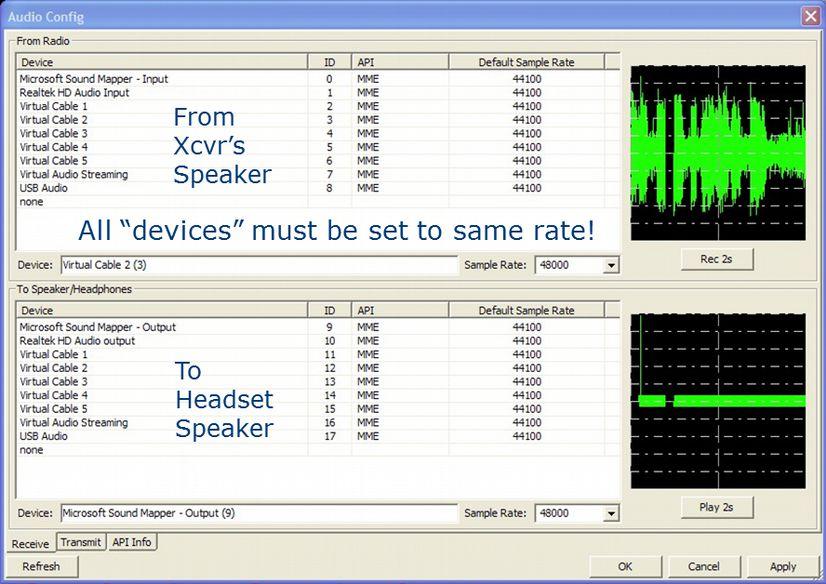

10 10 Audio Configuration Receive Transmit

11 11 Go to the Tools pull down menu and select Audio Config.. Sound cards/usb adapters, VAC and/or USB headsets installed on the PC will be listed. Select the PC s internal sound card or USB-audio dongle interface for the From/To Radio receive and transmit data. Select the USB headset or USB-audio dongle (if using a microphone / speaker rather than a headset) for the To Speaker/Headphones From Microphone voice out and input. To test the selection, click on the Rec 2s tab, look for a 2 second deflection in the scope (from the radio s speaker output audio or from speaking into the mic). Next, click on the corresponding output device and listen for an 800Hz tone followed by a deflection in the scope. If audio levels have not been previously set for use with another digital mode like PSK31, then they will need adjusting to avoid over or under driving your MIC input of your radio or over-driving the input of the sound card. See Receiving Digital Voice and Transmitting Digital Voice topics later in this document for these adjustments. The API tab shows Port Audio info. Note: Alternative rig connection: If you have a "9600" digital input and output on your radio (usually on a round DIN ACC connector), this is the best connection for every digital mode. Your radio (usually in a menu) should be configured for 9600 or "no pre-emphasis/de-emphasis" if it has this available. If the radio's configuration menu has a 1200/9600 setting, leave it permanently on If not available, FreeDV will still work fine with Mic/speaker connections. FreeDV must be stopped to change Audio and PTT configurations. Tools - Filter and Equalizers Under Tools, go to Filter. Adjustment of the Equalizer will depend upon the mic your voice characteristics. Testing has found voice quality may be improved with most mics by raising the mid-range frequency and Gain. Similar changes for the Speaker equalization may show improvements also. Adjustment of the LPC Post Filter may be adjusted to improve the subjective speech quality. On-the-air reports and experimentation will be needed to make final adjustments.
12 12 Tools - Recording Features Under Tools, options for Recording and Playback are available. Currently, the record/playback files (Mic in) must be sampled at 8 khz using 16 bit samples. Off the air DV may be recorded and played back through the PC speakers. Recordings that are to be played back into the radio mic input need to be 16 bit 8KHz sampled WAV files, others rates will not work (this applies to the voice keyer input as well). These dialog boxes will appear in the lower left hand corner below the options call sign/name text box while running. The recordings are 30 seconds in length which is the same time as a DV signal requires to move from the bottom to the top of the waterfall display.
 over an HF channel, it can be averaged using the Slow option. An SNR of approximately 3dB is required to begin decoding voice.")
.")
 pilot tone signal in the center of the FDM carriers.")
 is an end-to-end performance assessment of the transmitter, receiver and the propagation between them. (This is only available on 1600 mode).")
13 13 Receiving Digital Voice: SNR BER Receive Squelch Mode Control SNR: (Signal to Noise Ratio) is shown both in a visual indicator and numerically. Since SNR estimation will continually fluctuate (sometimes rapidly) over an HF channel, it can be averaged using the Slow option. An SNR of approximately 3dB is required to begin decoding voice. This would be a a rather low level noisy signal so some dropouts can be expected. Dependent on your receiving location s noise floor, expect good decoding at S4-5. To judge the quality of the data signal being received, expect an SNR of >15 to be indicated while receiving an S9 signal (again, this depends on your noise floor). Multi-path distortion, QRM and fading have an adverse effect on the SNR. Providing a SNR Report is a good way to report the received signal level. The higher the db value shown, the better. Sync: The dot appears when the received signal is in sync and can be decoded. Sync is derived from the BPSK (binary phase shift keying) pilot tone signal in the center of the FDM carriers. The small Red Marker at the bottom of the display (defaults at 1500 Hz) should be centered in between the BPSK signal tracks. (It can be within +/- 200Hz and still provide sync). BER: (Bit Error Rate) is an end-to-end performance assessment of the transmitter, receiver and the propagation between them. (This is only available on 1600 mode). BER is the percentage of errors defined by the formula: Squelch: When box is checked squelch is activated. The recommended default value is 1.5dB. Experience has found decoding of low SNR signals is possible in multipath/fades and QRM by taking advantage of the fast recovery/sync of FreeDV and your brain s FEC. Experiment with the squelch level in different signal and noise conditions. This setting correlates with the received signal SNR.
 for voice encoding giving it 3dB coding gain. 700B uses no FEC and 7 x 2 identical carriers for frequency diversity across 1.")
14 Mode 1600 Mode Spectrum Occupancy by Mode Mode: 700x mode works better in marginal conditions at the expense of audio quality. CODEC2 is running at a very low bit rate (650 bit/s) for voice encoding giving it 3dB coding gain. 700B uses no FEC and 7 x 2 identical carriers for frequency diversity across 1.5Khz to combat deep multipath fading 1600 mode (the default) has 300 bits of FEC in CODEC2 allowing up to a 10% BER before failing. This is currently the de-facto mode in use. It is not as robust, but has a narrower BW and better voice quality. Control: Start/Stop FreeDV must be in Start mode to begin receiving. With no FreeDV signal present, the waterfall will display band noise indicating audio is being routed to FreeDV s input. If no noise is observed, slowly raise the audio level using Windows sound level on the audio channel from the rig until the level is blue in color. A signal will have more amplitude and depending upon its strength, the carriers will change color and become lighter blue to red. Strong interference (SSB) and strong noise (QRN) will be red in color. Split Allows operation on two different frequencies within the audio pass band and is useful if you find the station you are working does not have their carriers centered on 1500 Hz think of it like an RIT control on an SSB transceiver. Note: Once the signal is in sync no additional tuning should be made. Analog This function switches off digital encoding and decoding so that you can communicate with a station on frequency running standard SSB (i.e. not DV). Voice Keyer This turns on a preconfigured recording and sends it as many times as you have programmed, with a gap between where it switches to receive and switches back to receive once all requested repeats have been completed. Once a valid signal is received (response to your CQ), the Voice keyer will terminate. One easy way to make a wave file recording uses the Windows Sound Recorder. Set the recorder to PCM Format and 8.000Khz, 8 bit Mono. With a PC microphone, make the CQ recording. Note: Loudness/Level is important and may take a couple tries to get the level correct to avoid over driving FreeDV s From Mic level. Save the file on your hard drive and then enter location in Tools>PTT Config Voice Keyer Wave File. PTT may be activated with either clicking this button or pressing the PC space bar. Note: The FreeDV GUI must be in focus to control PTT with the space bar.


15 15 Received signal displays. Default 1600 Mode Waterfall 700B Mode Waterfall 16 carrier FDM signal with 75Hz carrier spacing 14 carrier FDM signal with 75 Hz carrier spacing Red marker showing sync on DQPSK Pilot tone Change in color (amplitude) indicates fading 1600 Spectrum 700B Spectrum 16 carrier FDM signal with 75Hz carrier spacing 14 carrier FDM signal with 75 Hz carrier spacing with sync on center of Pilot tone at 1500Hz and frequency diversity to combat fading. Scatter Plot H/V points of the 4 QPSK phases with a tight cluster = good signal while fading = X shape From Radio Carrier audio level received at the input of the soundcard.


16 16 Audio to Speaker/Headphones Level of audio feeding the USB headset or Speaker. Adjust for max peaks < +/- 1 Timing Delta Plot showing estimate of the best sampling time. Changes indicate difference in TX/RX clock. Frequency Delta Frequency difference between receiving station and transmitting station frequency. Test Frame Errors Display of a test frame received. Straight lines are carriers with no errors. No signal on right. Multiple Signal Displays Audio Level Indicator
17 17 Multiple Signal Displays: Various displays are available to view the received signal. The default display is the waterfall. Click on the tabs below the current display to enable other displays. On transmit; the Frm Mic scope display is used for showing input audio from the Mic. To add a display, left click on the display tab and drag it vertically to the top. Next, release the left click button when a light blue background is showing. Displays can be arranged in various horizontal and vertical positions. Note: The added displays are not remembered, neither is any re-sizing of the overall program window, when the program is exited, the settings have to be repeated when the program is restarted. The waterfall color may be changed to monochrome or all blue hues with a right click inside the display window. Dark areas (called notches) indicate presence of multipath fading. Under these conditions (which are very common on HF), the spectrum display will show the 14 carriers constantly changing in amplitude. To obtain sync with the transmitted signal, precise (<200Hz) tuning is required but easily accomplished using the mouse for click tuning while observing the Waterfall or Spectrum displays. First, tune the receiver dial to the operating frequency (try USB). If a signal is present with an SNR of at least 2-3dB, decoding should start when the Red Marker at the bottom of the display is within the BPSK tracks (same waterfall appearance as PSK31) sync signal. If the Red Marker is not centered, then move the mouse cursor to the center and left click. Instantly, the signal should sync and voice will be decoded and sent to the headset or speakers. Once in sync, the radio s frequency dial should not be moved. FreeDV s AFC will track small drifts of the signal. Normally, the sync should be centered in the display at 1500 Hz to ensure the FDM signal for all modes is within the Tx/Rx band pass of the transceiver. Note: For the 700 mode, there is no center pilot/sync tone. Here, the sync is spread out across all the carriers (7+7 duplicated). The tuning is the same using the RedMarker centered inside signal. The tuning window, however it is only 60Hz wide. The input level from the radio to FreeDV should be adjusted using the Windows level control so the waterfall FDM carriers are mostly blue to green in color. If the level is set too high, the Level bubble will flash a warning. A slightly higher level may be needed for the Spectrum display. Stronger signals in the waterfall will display the carriers in different shades of blue, green, and red. Multipath selective fading results in a various darker patterns displayed in the waterfall as the amplitude of the carriers are being reduced. Note: When using a PC interfaced to a normal transceiver, Window s level sliders are used for all level adjustments. For SDR radios with Virtual Audio Cables such as PowerSDR, use the application s software adjustments (VAC Rx / Tx Gain).


 within the ham shack or RF getting into the system and under these conditions your audio will sound bad!")
18 18 Transmitting Digital Voice: Power Settings (graphics from Flex SDR): Keep ALC < 0 For typical 100w radio run < 25w average power FreeDV Transmit Display (Microphone input level) Verify the radio is operating at full output on SSB. The final output drive will be set using the sound device selected in Tools>Auto Config>Transmit>To radio. If not started, click on Start and then PTT. Quickly, adjust the RF output level and then watch the Frm Mic display while speaking in a normal voice. Adjust for 75% maximum deflection. Any voice input too high will cause clipping. Adjust the RF power for approximately 25w average with a 100w transceiver. This is an important setting to avoid distortion and lowering SNR at the receiving station. If necessary, reduce the drive level so that NO ALC action takes place. With no voice input, the thin center baseline on the display should not show any deflection. If it does, this indicates unwanted noise is being picked up (i.e. loud fans) within the ham shack or RF getting into the system and under these conditions your audio will sound bad!
19 19 Note: The DV signal has a high peak-to-average-power (PAPR) ratio meaning the RF amplifier needs additional head-room for the multi-carrier s higher peak power. Otherwise these peaks will be distorted and cause errors in the data sent and received then passed to the CODEC2 at the receive end for decoding. The peaks are quite fast and a conventional peak reading watt meter cannot accurately read the peak power. The average power output should not exceed 20-25% of your SSB transmitter/amplifier. Dependent on the power meter in use, average power will show some fluctuation in its readings. Tip: Call sign/name text data is being sent (repeated continuously during transmit) at a low bit rate (25bit/sec to 50 bit/sec). When initializing a contact, transmit for seconds minimum to ensure the receiving station receives your call and location in the text box. Text Box for Call ID/QTH info The call sign/name/location text is sent in a continuous loop and displayed in the text box. Use Tools>Options to enter your info for transmitting. The Clear button may be used to clear the box. Note: Under Tools>Options, Text Encoding box (Use Checksum on Rx) may be checked to receive error free Text information. However, depending on the SNR, this may have to be received several times before decoded without errors. The status is shown on the GUI (Checksums Good - Bad ) In the future, error free data received here will be used to trigger Events and in turn Process Events locally and across the net for interaction with web applications such as the FreeDV QSO Finder
20 20 Operating Tips: Where to Begin... Start by looking for activity on 20m, USB. FreeDV s FDM carriers make a distinctive noise but are half the width of SSB. Avoid confusing the digital EasyPal picture transfer OFDM signals on with DV. FreeDV QSO Finder ( written by John, K7VE is available on-line for the DV community. Current stations on the air, frequencies in use and a chat line are available. Just log on with your call sign (you need to be defined at hamqth.com before you will be allowed access, so set up your details there first). The list of suggested FreeDV frequencies are shown at the bottom of the page. You can also enter your own frequency in the box. All users who have entered a frequency (Frequency Selector) will be displayed on the left hand side of the page. Look here to see where to listen first. A call sign look up using hamqth.com is available for stations logged in. Just click on their call sign. Thank you, John! Currently, approximately 90% of the QSOs are using the default 1600 mode so look for it first. The differences are noticeable in the appearance of the waterfall. This 700 x mode will continue to see changes to improve the robustness and voice quality so check FreeDV.org for updates. Calling CQ Call sign/name text data is being sent (repeated continuously) at a low bit rate (25bit/sec) during transmit. When calling CQ or initializing a contact (calling a station), transmit for seconds minimum to ensure the receiving station receives your call and location in the text box. Keep this in mind when making a recording for the Voice Recorder. RFI and ambient shack noise RFI will cause noise and annoying sounds to be transmitted and decoded along with the voice. If experienced, a few ferrites on the interface cables and at the mic input may help remove this annoyance for the listener. This is very important otherwise the voice quality can be seriously degraded. Voice quality is dependent on the type of microphone but low cost PC electret mics can provide good voice audio. Logitech and Altec Lansing HS are known to work fine. The FreeDV equalizer (under tools/filter) can improve the audio quality. Minimize ambient noise pick up by lowering the mic level as low as possible while speaking in a normal level close to the mic element. Loud fans or other non-voice audio in the background may be picked up and transmitted as noise. Microphones in PC Laptops are generally not recommended. To check for noise pickup, watch the center green base line on the Tx display when not speaking into the mic. It will not show any deflection if no input noise is detected. Under Tools>Filter the Speex Mic Audio Pre-Processor is effective in removing noisy mics and noisy sound cards/usb. Under normal conditions, this option should remain enabled (default). More information Want more information on FreeDV? Check freedv.org often and the links including David Rowe s posts at Like FreeDV? Please consider a donation at freedv.org for the developers. Acknowledgments: Thanks to David Rowe, VK5DSG for his technical support, Bruce Perens, K6BP for his inspiration and Rick Peterson, WA6NUT for review of the original document. Corrections/questions/additions/comments may be directed to: mel@melwhitten.com Mel Whitten, KØPFX 02-Sep-13 Rev Oct-15 Rev 1.1 Updates - Ed Durrant, DD5LP 15-Oct-15 Rev 1.1
Ap A ril F RRL RRL P ro r gra r m By Dick AH6EZ/W9
 April 2013 FRRL Program By Dick AH6EZ/W9 Why Digital Voice? Data speed or RF bandwidth reduction Transmission by shared digital media such as T1s Security and encryption PCM or ADPCM first US Patent in
Screen shots vary slightly according to Windows version you have.
 http://www.w1hkj.com/fldigihelp/audio_adjust_page.html Screen shots vary slightly according to Windows version you have. Receive audio Setting the correct hardware, operating system, and fldigi received
Disable Windows Sounds
 9/28/2017 - K3CT Disable Windows Sounds Users may want to disable the Windows Sounds so none of the Windows OS sounds are transmitted on the radio. Install the Icom Drivers, Select COM port, Disable Power
Introduction to FLDIGI Karl Frank, W2KBF
 Introduction to FLDIGI Karl Frank, W2KBF Purpose To Provide Fair Lawn ARC members with an Introduction to FLDIGI; Demonstrate Use of FLMSG to send an errorfree text message on an ICS form. (The name stands
Configuring Digital Mode for Radios with USB
 Configuring Digital Mode for Radios with USB Introduction Newer Icom radios are now equipped with a USB (Universal Serial Bus) interface. These radios do not require you to purchase, and use an interface
How do I get started on rtty (or psk)?
?") How do I get started on rtty (or psk)? The data modes have become particularly popular in recent years, with RTTY and PSK31 being heard almost every evening, particularly on 20 metres. So, now is a very
How do I get started on rtty (or psk)? The data modes have become particularly popular in recent years, with RTTY and PSK31 being heard almost every evening, particularly on 20 metres. So, now is a very
SPECS FEATURES SUPPLIED ACCESSORIES. HF All Band Transceiver
 718 HF All Band Transceiver RX 0.030-29.999999MHz* TX 1.800-1.999999 MHz** 3.500-3.999999 MHz** 7.000-7.300000 MHz 10.100-10.150000 MHz 14.000-14.350000 MHz 18.068-18.168000 MHz 21.000-21.450000 MHz 24.890-24.990000
Testing Motorola P25 Conventional Radios Using the R8000 Communications System Analyzer
 Testing Motorola P25 Conventional Radios Using the R8000 Communications System Analyzer Page 1 of 24 Motorola CPS and Tuner Software Motorola provides a CD containing software programming facilities for
VARA HF Modem Specification Revision Oct30, 2017 Jose Alberto Nieto Ros, EA5HVK
 VARA HF Modem Specification Revision 1.0.0 Oct30, 2017 Jose Alberto Nieto Ros, EA5HVK 1.0 Overview: VARA HF Modem is a propietary system developed by Jose Alberto Nieto Ros EA5HVK and can be used under
A Digital HF Mode By N4UFP Marc Tarplee. Tweaks by K7AGE
 A Digital HF Mode By N4UFP Marc Tarplee Tweaks by K7AGE A Digital HF Mode By N4UFP Marc Tarplee Tweaks by K7AGE First, a little bit about me I was first licensed in 1968 I ve been around video since high
LnR Precision, Inc. 107 East Central Avenue, Asheboro, NC
 LD5 CW/SSB QRP Transceiver Quick guide manual Description: At the development base of the digital signal processing unit, an algorithm is embedded for IQ processing of the channels with phase suppression
Radio <-> Computer Interfacing. RATS 25-Mar-17 Rob G2FGT
 Radio Computer Interfacing RATS 25-Mar-17 Rob G2FGT Disclaimer! I m no good at home brew this is not about how to build an interface no DIY advice I just want to operate radios, make contacts this
Basic Transceiver tests with the 8800S
 The most important thing we build is trust ADVANCED ELECTRONIC SOLUTIONS AVIATION SERVICES COMMUNICATIONS AND CONNECTIVITY MISSION SYSTEMS Basic Transceiver tests with the 8800S Basic Interconnects Interconnect
Application Note: Testing P25 Conventional Radios Using the Freedom Communications System Analyzers
 : Testing P25 Conventional Radios Using the Freedom Communications System Analyzers FCT-1007A Motorola CPS and Tuner Software Motorola provides a CD containing software programming facilities for the radio
Elmer Session Hand Out for 3/3/11 de W6WTI. Some Common Controls Found On Amateur Radio Transceivers. (From ARRL web site tutorial)
") Elmer Session Hand Out for 3/3/11 de W6WTI Some Common Controls Found On Amateur Radio Transceivers. (From ARRL web site tutorial) The placement of the controls may vary from manufacturer to manufacturer
Elmer Session Hand Out for 3/3/11 de W6WTI Some Common Controls Found On Amateur Radio Transceivers. (From ARRL web site tutorial) The placement of the controls may vary from manufacturer to manufacturer
Welcome to Ham Radio 101 & 201
 Welcome to Ham Radio 101 & 201 Sponsored by HF Operating David W6DTW Sponsored by Basic Bands and Propagation New Bands! 630 meters 2,200 meters Requires application and approval Basic Bands and Propagation
Using an ASIO Audio Interface and Digital Audio Workstation Software with openhpsdr Revision 3 14 Jun 2015 WU2O
 Using an ASIO Audio Interface and Digital Audio Workstation Software with openhpsdr Revision 3 14 Jun 2015 WU2O Introduction Many people are using relatively low cost, professional audio interfaces such
PC Tune PC Tune Test Procedures for 5100 Series Portable Radios
 PC Tune PC Tune Test Procedures for 5100 Series Portable Radios Part Number 002-9998-6513014 August 2008 Copyright 2006, 2007, 2008 by EFJohnson Technologies The EFJohnson Technologies logo, PC Configure,
What is it? What do I need? How do I use it? Randy Hall K7AGE
 PSK-31 What is it? What do I need? How do I use it? Randy Hall K7AGE First, a little bit about me I was first licensed in 1968 I ve been around video since high school Built a TV camera as high school
Instructions for the W0NE Remote HF Rig, IC-7300
 Instructions for the W0NE Remote HF Rig, IC-7300 The ICOM IC-7300 rig at the Witoka site is installed and connected up as a RemoteHams.com Server. This system is being opened to all W0NE club members to
HF Digital Mode Primer
 HF Digital Mode Primer By Val Campbell K7HCP INTRODUCTION Getting started using the Amateur Radio Digital Modes of communications can be confusing and frustrating at times but it doesn t have to be that
What is it? What do I need? How do I use it? Randy Hall K7AGE
 PSK-31 What is it? What do I need? How do I use it? Randy Hall K7AGE First, a little bit about me I was first licensed in 1968 I ve been around video since high school Built a TV camera as high school
Sound Card Oscilloscopes and Digital Modes. K3EUI Barry Feierman June 2016
 Sound Card Oscilloscopes and Digital Modes K3EUI Barry Feierman June 2016 Hardware for Digital Modes Interface - between computer and radio by two audio cables or by a single usb cable Sound Card INPUT
PARA Field Day 2010 Digital GOTA Station Setup 6/12/2010
 PARA Field Day 2010 Digital GOTA Station Setup dranch@trinnet.net 6/12/2010 Table of Contents Physically connecting up the radio...2 Configure the FT-897...2 Initial Signalink settings...2 Initial Windows
MK2R/MK2R+ and Logger32 Setup
 Router setup: MK2R/MK2R+ and Logger32 Setup Note: The specific port numbers are not important. The key is consistency - the same port number must be used for a specific function in both Router and the
TI RigExpert. User s manual. USB Transceiver Interface
 TI-5000 RigExpert USB Transceiver Interface User s manual . Table of contents Introduction Operating the TI-5000 Front and rear panels Transceiver and computer connection Updating the firmware Annexes
Delta 44 Quick Start Guide
 Delta 44 Quick Start Guide The M-Audio Delta 44 is a high grade professional sound card. When setup properly for use with the SDR- 1000, the results speak for themselves. Unbelievably high dynamic range
Mic Mate Pro. User Manual
 R Mic Mate Pro User Manual Mic Mate Pro Features Congratulations and thank you for purchasing the MXL Mic Mate Pro. This device is designed to minimize your setup for recording and allow for professional
BUXCOMM 2007 RASCAL GLX OPERATOR S MANUAL Before we begin, let s perform the initial setup:
 BUXCOMM 2007 RASCAL GLX OPERATOR S MANUAL Before we begin, let s perform the initial setup: Sound Card CONFIGURATION: Most soundcards use 3.5mm (1/8") jack for line and/or microphone input. Use the LINE
RIGblaster plug & play Owners Manual
 RIGblaster plug & play Owners Manual Revision 1.0 May 2006 DO NOT PLUG IN THE RIGblaster plug & play! YOU MUST INSTALL THE DRIVERS FROM THE CD ROM FIRST! Thank for purchasing a RIGblaster plug & play.
RigExpert TI-7 USB Transceiver Interface User s manual
 RigExpert TI-7 USB Transceiver Interface User s manual Please read this manual before attempting to use the RigExpert TI-7 device. - - 2 - Table of contents 1. What is a RigExpert TI-7?... 4 2. Specifications...
User Manual USB Condenser Microphone
 User Manual USB Condenser Microphone MICF-3001 Overview 1 Setting Up 1 Using the microphone with Windows 7/8/10 PC 3 Using a headphone with CF3001 4 Monitor your voice level (Computer system feature) 5
M-16DX 16-Channel Digital Mixer
 M-16DX 16-Channel Digital Mixer Workshop Using the M-16DX with a DAW 2007 Roland Corporation U.S. All rights reserved. No part of this publication may be reproduced in any form without the written permission
July 27, 2016 Class By Israel AD7ND & Andy K3WYC
 TBARC Programs Digital Modes Class July 27, 2016 Class By Israel AD7ND & Andy K3WYC Before We Start This material was put together as an attempt to fulfill a request from the TBARC Board for a digital
MIDLAND PROGRAMING G14
 MIDLAND PROGRAMING G14 1. PROGRAMMING CAPABILITY Welcome to the MIDLAND Programming software! It s a programming software specifically designed for G14 and must be used in conjunction with the dedicated
DMR Application Note Testing MOTOTRBO Radios On the R8000 Communications System Analyzer
 DMR Application Note Testing MOTOTRBO Radios On the R8000 Communications System Analyzer April 2 nd, 2015 MOTOTRBO Professional Digital Two-Way Radio System Motorola and MOTOTRBO is registered in the U.S.
Application Note: DMR Application Note Testing MOTOTRBO Radios On the Freedom Communications System Analyzer
 : DMR Application Note Testing MOTOTRBO Radios On the Freedom Communications System Analyzer MOTOTRBO Professional Digital Two-Way Radio System Motorola and MOTOTRBO is registered in the U.S. Patent and
Icom IC-9100 HF/VHF/UHF transceiver
 263 Walsall Road, Great Wyrley, Walsall, WS6 6DL Established 1997. Open Monday - Friday 9am - 5pm and Saturday 9.30am - 4pm Tel: 01922 414 796 Fax: 01922 417829 Skype: radioworld_uk Icom IC-9100 HF/VHF/UHF
DigiKeyer and N1MM Logger+ Setup
 DigiKeyer and N1MM Logger+ Setup Router setup: Note: The specific port numbers are not important. The key is consistency - the same port number must be used for a specific function in both Router and the
PC to Radio Audio and Key-line Interface
 PC to Radio Audio and Key-line Interface Background - This simple interface was developed to capacitive couple audio signals between a radio and PC, to provide a means of adjusting audio levels between
3000 Hz. Average Noise
 PSK-31 Dave, K6AIX ddanner@earthlink.net 01-21-2007, 2007, D. H. Danner 1 What is PSK-31? Digital Text, ASCII Narrow Bandwidth, PSK, 31 Hz Low Power, < 25 watts Out Performs Teletype, Packet Low Cost,
ISOTERM-MULTICON USB TRAVELLER
 ISOTERM-MULTICON USB TRAVELLER SETTING UP INSTRUCTIONS FOR DATA INTERFACE de G3LIV Welcome to the World of PSK-31. Thank you for purchasing this ISOTERM USB interface. I hope it will give you hours of
HF Digital Mode Overview
 HF Digital Mode Overview Gary Wescom June 5 th, 2006 This is a short description of some of the major digital modes currently used on the HF ham bands. There are hundreds of different communications protocols
LD5 CW/SSB QRP Transceiver SDR /DSP
 LD5 CW/SSB QRP Transceiver SDR /DSP Quick guide manual Description: At the development base of the digital signal processing unit, an algorithm is embedded for IQ processing of the channels with phase
SDR 4++ Dual Diversity SDR Receiver. Operating Guide. version 1.0
 Cross Country Wireless, 7 Thirlmere Grove, BOLTON, BL4 0QB, UK Email chrism@crosscountrywireless.net Web page http://www.crosscountrywireless.net Telephone +44 (0) 1204 410626 Mobile / Workshop +44 (0)
Station Automation: Implementation of DX Labs and components
 Station Automation: Implementation of DX Labs and components Hardware requirements: Note that most of benefits of using DX Labs suite of station automation programs can be realized without connecting between
Overview of NBEMS modes using FLDIGI
 Overview of NBEMS modes using FLDIGI K3EUI Barry Overview K3EUI - know your subject/subjects Digi Modes - can you identify them by sound Hardware needed to receive / transmit Modulation basics: AM, FM,
Mbox Basics Guide. Version 6.4 for LE Systems on Windows XP and Mac OS X. Digidesign
 Mbox Basics Guide Version 6.4 for LE Systems on Windows XP and Mac OS X Digidesign 2001 Junipero Serra Boulevard Daly City, CA 94014-3886 USA tel: 650 731 6300 fax: 650 731 6399 Technical Support (USA)
Technician License Course Chapter 5. Lesson Plan Module 11 Transmitters, Receivers and Transceivers
 Technician License Course Chapter 5 Lesson Plan Module 11 Transmitters, Receivers and Transceivers Generalized Transceiver Categories Mobile Single Band Dual Band All Band Multimode Handheld (HT) VHF/UHF
Development of the QSX transceiver kit
 Development of the QSX transceiver kit Norfolk Amateur Radio Club Wednesday 9-Jan-2019 Hans Summers, G0UPL http://qrp-labs.com QCX 5W CW transceiver kit QRP Labs CW Xcvr Introduced at YOTA 2017 summercamp
Pushing performance to the pinnacle
 Pushing performance to the pinnacle The latest DSP technologies developed for the IC-7800/7700 plus over 45 years of analog circuit expertise give the IC-7600 the performance advantage. The flagship's
SEMDXA Monthly Meeting May 8, Larry Gauthier, K8UT
 SEMDXA Monthly Meeting May 8, 2015 Larry Gauthier, K8UT 1 Agenda Digital Mode Anatomy Compare CW to RTTY Preparing to Operate RTTY Create Your Shopping List Connecting the RTTY Components Insert Tab A
5 State Radio Buttons - (enabled under program control during receive ) as follows:
 as follows:") WinDRM Docs Release 1.2 was developed by Cesco, HB9TLK from a relatively new broadcast WinDRM standard called Digital Radio Mondiale (DRM) and it s open source encoder/decoder named Dream (http://drm.sourceforge.net/).
WinDRM Docs Release 1.2 was developed by Cesco, HB9TLK from a relatively new broadcast WinDRM standard called Digital Radio Mondiale (DRM) and it s open source encoder/decoder named Dream (http://drm.sourceforge.net/).
QSY Society Field Day 2011 PSK31 Training By KC2QFR - Fred Lauricella Introduction:
 QSY Society Field Day 2011 PSK31 Training By KC2QFR - Fred Lauricella Introduction: The Digital mode PSK31 was the creation of Peter Martinez. Introduced in a 1998 RSGB article by G3PLX in the societies
CVARC BASIC RADIO TECH TALK. DIGITAL RADIO OPERATIONS 19 October 2018 Bill Willcox, Rob Hanson, Jaap Goede
 CVARC BASIC RADIO TECH TALK DIGITAL RADIO OPERATIONS 19 October 2018 Bill Willcox, Rob Hanson, Jaap Goede Basic Radio Tech Talk Digital Operations Basic Information Bill Willcox Types of Digital Operations
All Things icom Microphone Basics
 All Things icom Microphone Basics 22 June 2016 - Reprinted with permission from the Heil. http://www.heilsound.com/amateur/support/dsp-settings/all-things-icom Important! The icom 7300 has been updated
ISOTERM-MULTICON TRAVELLER
 ISOTERM-MULTICON TRAVELLER SETTING UP INSTRUCTIONS FOR DATA INTERFACE de G3LIV July 2012 Page 1-1 Welcome to the World of PSK-31. Thank you for purchasing this ISOTERM. I hope it will give you hours of
FT8 WHY NOW? This month, (earliest Jan. 25) Bouvet Isl.!!! 54 deg. 25 min. South, 3 deg. 22 min. East 1000 miles North of Antarctica...
 Bouvet Isl.!!! 54 deg. 25 min. South, 3 deg. 22 min. East 1000 miles North of Antarctica...") FT8 WHY NOW? This month, (earliest Jan. 25) Bouvet Isl.!!! 54 deg. 25 min. South, 3 deg. 22 min. East 1000 miles North of Antarctica... 3Y0Z Bouvet Island https://www.bouvetdx.org/the-island/ Rare DX!
FT8 WHY NOW? This month, (earliest Jan. 25) Bouvet Isl.!!! 54 deg. 25 min. South, 3 deg. 22 min. East 1000 miles North of Antarctica... 3Y0Z Bouvet Island https://www.bouvetdx.org/the-island/ Rare DX!
Weak Signal Digital Modes. 9V1KG Klaus Aug 2016
 Weak Signal Digital Modes 9V1KG Klaus Aug 2016 Content Introduction What makes these modes so popular? Station setup and interfacing Digital Modulation PSK 31 JT-65/JT-9 PSK Reporter 9V1KG - Weak Signal
N7YG Digital Engine User Guide Updated 1 September 2017
 N7YG Digital Engine User Guide Updated 1 September 2017 The N7YG Digital Engine (DE) is basically a scaled down version of PSKExpress (PSKE) and provides the basics needed to operate the digital modes
KENWOOD SKY COMMAND SYSTEM
 KENWOOD SKY COMMAND SYSTEM Operation Manual KENWOOD COMMINICATIONS CORPORATION KENWOOD COMMUNICATIONS CORPORATION This operation manual is used for the KENWOOD SKY COMMAND SYSTEM (hereinafter referred
TS-590S TechNote: SSB Audio Handling
 TS-5S TechNote: SSB Audio Handling 1 TS-5S TechNote: SSB Audio Handling by Ian Wade, G3NRW g3nrw-radio@ntlworld.com Version 1.1 2 October 212 Introduction The aims of this TechNote are: To summarize the
INSTRUCTION MANUAL IP REMOTE CONTROL SOFTWARE RS-BA1
 INSTRUCTION MANUAL IP REMOTE CONTROL SOFTWARE RS-BA FOREWORD Thank you for purchasing the RS-BA. The RS-BA is designed to remotely control an Icom radio through a network. This instruction manual contains
- Setup and Operation
 - What is JT-65-65 tones sent in 200 HZ bandwidth - Developed for EME - Setup and Operation - Soundcard interface - WSJT-X software (free) - On-Air Demo - PC, Soundcard & Rig Ed Erny - NZ1Q St Petersburg
WIRES-X Portable Digital Node Function. Instruction Manual
 Wide-Coverage Internet Repeater Enhancement System WIRES-X Portable Digital Node Function Instruction Manual Please read this Instruction Manual carefully for appropriate procedure. Preparation Procedure
M-Powered Basics Guide
 M-Powered Basics Guide Version 6.8 for M-Powered Systems on Windows or Macintosh Digidesign 2001 Junipero Serra Boulevard Daly City, CA 94014-3886 USA tel: 650 731 6300 fax: 650 731 6399 Technical Support
micro 2R and WriteLog setup guide
 Router setup: micro 2R and WriteLog setup guide Note: The specific port numbers are not important. The key is consistency - the same port number must be used for a specific function in both Router and
Lesson 2 HF Procedures and Practices Overview
 Lesson 2 HF Procedures and Practices Overview On Display QSL Cards On Display Icom IC-7000 On Display Buxcomm Rascal Sound card interface: PSK31 SSTV RTTY Packet Digital Voice MFSK16 -more- Operating Techniques
CI-22. BASIC ELECTRONIC EXPERIMENTS with computer interface. Experiments PC1-PC8. Sample Controls Display. Instruction Manual
 CI-22 BASIC ELECTRONIC EXPERIMENTS with computer interface Experiments PC1-PC8 Sample Controls Display See these Oscilloscope Signals See these Spectrum Analyzer Signals Instruction Manual Elenco Electronics,
The Icom IC Adam Farson VA7OJ. A New Top-class HF/6m Transceiver. IC-7700 Information & Links
 The Icom IC-7700 A New Top-class HF/6m Transceiver Adam Farson VA7OJ IC-7700 Information & Links Copyright 2008 North Shore Amateur Radio Club NSARC HF Operators IC-7700 1 IC-7700 front panel This is a
micro KEYER and N1MM Logger+ Setup
 micro KEYER and N1MM Logger+ Setup Router setup: Note: The specific port numbers are not important. The key is consistency - the same port number must be used for a specific function in both Router and
Using a Software Defined Radio As a Panadapter
 Using a Software Defined Radio As a Panadapter by Dave Core, K8WDA Presented to the Northern Kentucky Amateur Radio Club by Dave Core, K8WDA, on Oct. 9, 2017. What Is a Panadapter? Panadapter aka: Panoramic
WIRES-X Portable Digital Node Function. Instruction Manual
 Wide-Coverage Internet Repeater Enhancement System WIRES-X Portable Digital Node Function Instruction Manual Please read this Instruction Manual carefully for appropriate procedure. Preparation Procedure
FT-991 MENU MODE. changes in factory defaults are yellow
 changes in factory defaults are yellow FT-991 MENU MODE No. Menu Function Available Settings Default Value 001 AGC FAST DELAY 20-4000 (20msec/step) 300msec 002 AGC MID DELAY 20-4000 (20msec/step) 700msec
Microphone audio, from the MFJ-1278B to your transmitter. Ground, audio and PTT common. Push-to-talk, to allow the MFJ-1278B to key your transmitter.
 Computer interfacing, covered in the previous chapter, is only half the interfacing task. The other half is connecting your MFJ-1278B to your radios. MFJ-1278B Radio Ports Interfacing the MFJ-1278B to
RIGblaster standard models M8, M4, RJ
 RIGblaster standard models M8, M4, RJ rig to sound card interfaces OWNER S MANUAL 4TH EDITION IF YOU CAN'T FIND IT HERE GO TO OUR SUPPORT PAGE: http://www.westmountainradio.com/support.htm West Mountain
ADJUSTING YOUR HF RECEIVER
 ADJUSTING YOUR HF RECEIVER N5KIP January 31, 2017 Disclaimers What works on one model of radio might not work well on another CW (narrow bandwidth) and SSB (wider bandwidth) will require different receiver
Computer Ham Rig 1 V p-p SC Mic In Spkr Out 1 V p-p 10 mv p-p SC Spkr Out Attenuator Mic In +- 12V Closure to Gnd Serial Out (RTS) Level Shifter PTT
 Level Shifter PTT") Get Your Feet Wet with PSK Clint Hurd - KK7UQ Terry Dettman - WX7S - SGC Presented at SEAPAC Seaside, Oregon June, 00 Get Your Feet Wet with PSK Outline of Presentation Basics -Sound Card Applications
Get Your Feet Wet with PSK Clint Hurd - KK7UQ Terry Dettman - WX7S - SGC Presented at SEAPAC Seaside, Oregon June, 00 Get Your Feet Wet with PSK Outline of Presentation Basics -Sound Card Applications
Interface Genius Modem Instruction Manual v1.2.4
 Interface Genius Modem Instruction Manual v1.2.4 Interface Genius Modem is a USB / LAN controlled SO2R radio interface remote radio modem. It is designed to be controlled by a Windows application, and
Click on the numbered steps below to learn how to record and save audio using Audacity.
 Recording and Saving Audio with Audacity Items: 6 Steps (Including Introduction) Introduction: Before You Start Make sure you've downloaded and installed Audacity on your computer before starting on your
Mastr III P25 Base Station Transmitter Tune-up Procedure
 Mastr III P25 Base Station Transmitter Tune-up Procedure 1. Overview The Mastr III Base Station transmitter alignment is performed in several steps. First, the Transmit Synthesizer module is aligned to
Guardian and DL3282 Modem Interface Technical Service Application Note
 Guardian and DL3282 Modem Interface Technical Service Application Note OVERVIEW The following document is designed to provide information for the implementation of the Guardian Wireless Modem/Analog Radio
LNR Precision Mountain Topper MTR-4B and MTR-5B REV 2.0 User Manual for use with versions with 16 x 2 display.
 LNR Precision Mountain Topper MTR-4B and MTR-5B REV 2.0 User Manual for use with versions with 16 x 2 display. Four band MTR 4B shown Overview: The Mountain Topper Rigs are designed to be a very small,
A Simple SO2R Contest Station
 Andrew Roos, andrew.roos@mweb.co.za June 2007 A Simple SO2R Contest Station Figure 1 - The SO2R Operating Position at SO2R stands for Single Operator Two Radio, and describes a single-operator station
Digital Modes and Sound Card Interfaces for Amateur Radio
 Digital Modes and Sound Card Interfaces for Amateur Radio Presented by: Mark Landress WB5ANN For the Regular Meeting of the Oak Forest Amateur Radio Club, KE5TRB Houston, Texas February 21, 2009 1 Setup
Remote Rig Control. By Chris Bigelow, VA3ECO
 Remote Rig Control By Chris Bigelow, VA3ECO Whether you are away from home for work or pleasure, it s hard to lug your radio and antenna with you. I faced this problem recently and found setting up a remote
GETTING THE MOST FROM YOUR HF TRANSCEIVER FRED KEMMERER, AB1OC JANUARY 10 TH, 2017
 GETTING THE MOST FROM YOUR HF TRANSCEIVER FRED KEMMERER, AB1OC JANUARY 10 TH, 2017 Topics Its mostly about the receiver Transmitter/amplifier operation tips and tricks Common operating scenarios Not to
Digital EmComm with NBEMS
 Digital EmComm with NBEMS Dave Kleber KB3FXI O'Hara Twp EMA kb3fxi@arrl.net Harry Bloomberg W3YJ Assistant SEC WPA ARRL Section w3yj@arrl.net Why Digital EmComm? Think back to your last public service
Testing Motorola DMR MOTOTRBO Radios with the Cobham 3920B Radio Test Platform
 Application Note Testing Motorola DMR MOTOTRBO Radios with the Cobham 3920B Radio Test Platform The Cobham 3920B is the complete tool for anyone wishing to test Analog or Digital MOTOTRBO mobile or portable
MXL USB.006.
 MXL USB.006 www.mxlmics.com Congratulations on your purchase of the MXL USB.006 which uses a large 32mm gold diaphragm capsule for added warmth. MXL microphones are the result of world-class engineering
SUBELEMENT T4. Amateur radio practices and station set up. 2 Exam Questions - 2 Groups
 SUBELEMENT T4 Amateur radio practices and station set up 2 Exam Questions - 2 Groups 1 T4A Station setup: connecting microphones; reducing unwanted emissions; power source; connecting a computer; RF grounding;
DSP-599zx Version 5.0 Manual Supplement
 DSP-599zx Version 5.0 Manual Supplement New Features Timewave Technology Inc. has extended the leading edge technology that has made the DSP-599zx the #1 signal processor in HF communications. Today, you
AfedriNet Review. SDRZone. AfedriNet SDR Review
 AfedriNet Review SDRZone AfedriNet SDR Review December 31st 2013 Reviewed by NI0Z AFEDRI SDR-Net http://www.afedri-sdr.com/ Downloads & Manuals http://www.afedri-sdr.com/index.php/downloads AFEDRI SDR-Net
DESIGN, SETUP AND OPERATION CLALLAM COUNTY AMATEUR RADIO CLUB MAY 9, 2018 BILL PETERSON K7WWP
 DESIGN, SETUP AND OPERATION CLALLAM COUNTY AMATEUR RADIO CLUB MAY 9, 2018 BILL PETERSON K7WWP FT8 DESIGN AUTHORS Joe Taylor K1JT Professor of Physica (Emeritus) Princeton University Nobel Prize winner
Introduction to NBEMS
 Introduction to NBEMS Developed for Kings County ARES By Bob Jordan, KD2BQM ARRL: VE, FI, FE Original slides used and modified for this presentation were developed by Harry Bloomberg W3YJ, Western Pennsylvania
CS3000 ALIGNMENT REFERENCE MANUAL FM HANDHELD TRANCEIVER. Connect Systems Incorporated 1802 Eastman Ave., Suite 116 Ventura CA Version 1.
 CS3000 ALIGNMENT REFERENCE MANUAL FM HANDHELD TRANCEIVER Connect Systems Incorporated 1802 Eastman Ave., Suite 116 Ventura CA 93003 Version 1.00 Copyright 2010 by Connect Systems Incorporated TABLE OF
ISOTERM-MULTIMODE. INSTRUCTIONS for DATA-CW-FSK-INTERFACE. de G3LIV July 2012 Series 5
 ISOTERM-MULTIMODE INSTRUCTIONS for DATA-CW-FSK-INTERFACE de G3LIV July 2012 Series 5 Welcome to the World of DATA. ISOTERM-MULTIMODE The ISOTERM MULTIMODE as its name implies is designed to be used with
RIGblaster plus USB. rig to sound card interface OWNERS MANUAL 5TH EDITION.
 RIGblaster plus USB rig to sound card interface OWNERS MANUAL 5TH EDITION WEST MOUNTAIN RADIO http://www.westmountainradio.com 1020 Spring City Drive, Waukesha, WI 53186 tel 262.522.6503 fax 262.522.6504
Good luck and enjoy your new radio.
 TM 5-Step SDR-1000 Quick Start Guide Installation and The purpose of this guide is to get you on the air as quickly as possible so you can begin to enjoy your new SDR-1000. This document is not a substitute
AMPLIFi FX100 PILOT S GUIDE MANUEL DE PILOTAGE PILOTENHANDBUCH PILOTENHANDBOEK MANUAL DEL PILOTO 取扱説明書
 AMPLIFi FX100 PILOT S GUIDE MANUEL DE PILOTAGE PILOTENHANDBUCH PILOTENHANDBOEK MANUAL DEL PILOTO 取扱説明書 40-00-0357-D Firmware v2.50.2 Pilot s Guide also available at line6.com/support/manuals 2016 Line