3.9 GHz System (AH1) XFEL WP46
|
|
|
- Avis Singleton
- 6 years ago
- Views:
Transcription

1 3.9 GHz System (AH1) XFEL WP46 14th European XFEL Machine Advisory Committee Meeting 02 May 2016 Paolo Pierini, INFN & DESY Elmar Vogel, DESY + INFN/DESY contributors PPT version 1 26/04/2016


2 Outline Status presented at Nov 2015 MAC Operational experience during injector commissioning Spare module preparation Plans for R&D at CW for upgrades
3 WP46: 3.9 GHz System STATUS PRESENTED AT LAST MAC
4 Status at 13 th MAC (11/15) and report Module installed & visited by MAC in the Injector Waiting for first cooldown and RF characterization 1 cavity tested with tuner, magshield, coupler at AMTF MAC Report As the 3.9 GHz module has not been tested before installation, maybe some extra commissioning time needs to be scheduled. The commissioning team is well aware that the 3.9 GHz module has not been tested before installation. It is very appropriate to cool down as soon as possible to find out if any problem exists with this and other parts of the beamline.
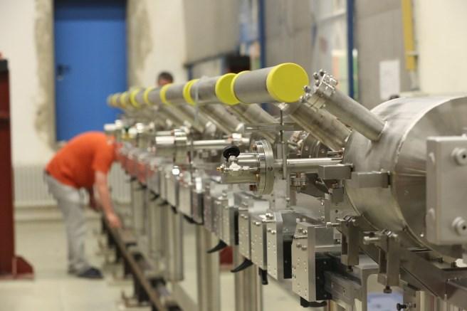
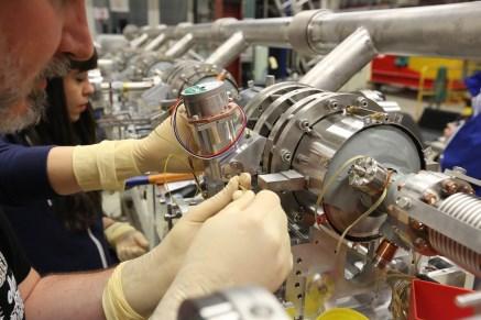
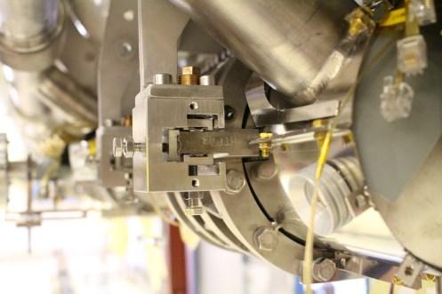
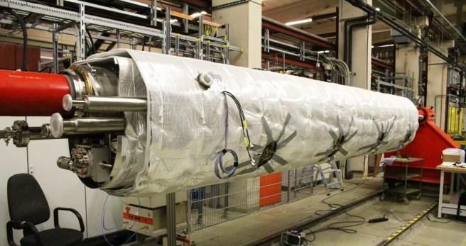
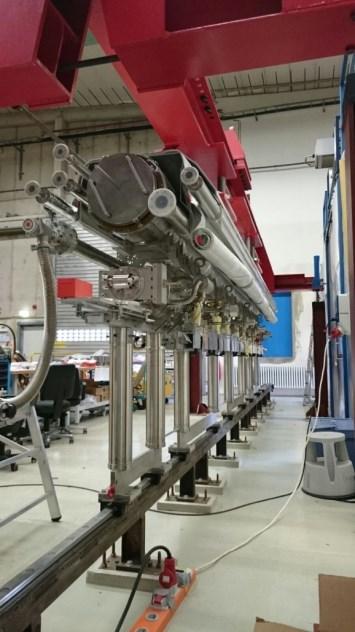
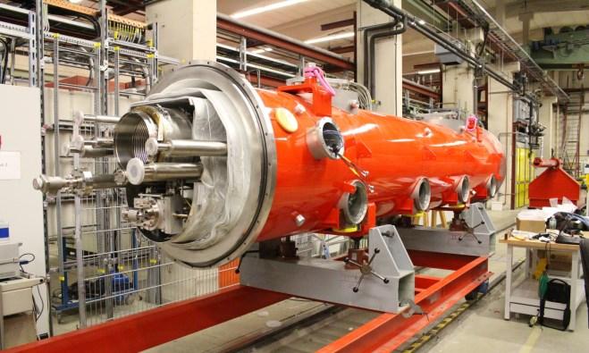
5 WP46: 3.9 GHz System MODULE ASSEMBLY AND INSTALLATION
6 Timeplan presented at 12 th MAC Meeting Cavity Preparation CR String Assembly (2 Wks) Module Assembly (7 Wks) Installation, technical commissioning (8 Wks) P. Pierini, 14th XFEL MAC Meeting 12 th MAC 02/May/2016
7 14 weeks from cavities to tunnel Status and plans for the 3.9 GHz section of XFEL Module assembly timeline Where When Activity CLEAN ROOM (3 wks) ROLL-OUT AREA ON GIRDER (2 wks) ROLL-OUT AREA SUSPENDED (2 wks) CANTILEVER (4 wks) FLOOR SUPPORT (3 wks) WK25 WK26 WK27 WK28 WK29 WK30 WK31 WK32 WK33 WK34 WK35 WK36 WK37 WK38 WK39 Clean room preparation, last coupler installed on cavities String installation start. Cavity connections Finish installation. String Roll-out Partial magnetic shield installation and tuner installation, T sensors 2 phase line welds, T sensor installation completion, tuner motor Suspension from cold mass, completion of magnetic shield, alignment End of string alignment (2 pass and final survey), transfer to cantilever, preparation of 2K thermal sinking (HOM, motor), HOM notch filter tuning Weld of the magnet package current leads, weld of the warmup circuit RF cables, completion mag shield, HOM thermal sinks, installation of coupler cones, cable thermalization, start assembly of 4K shield parts Finalization of 4K/80K shields and MLI blankets Vessel roll-on, post bracket/suspension of the Cold Mass on the Vacuum Vessel, longitudinal pre-alignment of CM to VV, transfer to floor supports CM to VV alignment, start of coupler installation Finish coupler installation on one side, install coupler vacuum pump line Coupler side two, coupler vacuum, beam vacuum & leak check Transport to Tunnel


8 Major Assembly Milestones July September
9 Activities in between


10 Final Preparation stages in tunnel November th MAC Assembly WG distribution Injector String Integration Dec 10: Start cooldown Dec 15, cavity pre-tuning Dec 16, calibration: AH1 Ready 50 kw LLRF & Klystron calibration on load
11 WP46: 3.9 GHz System MODULE RF COMMISSIONING

12 Cavity vertical tests at INFN/LASA First cavity vertical test 26-Sep-14 and last 11-Feb-2015
13 RF Commissioning in Tunnel Infrastructure aspects, workload of main linac module testing activities and schedule delays made it impossible to perform an integral test of the module before tunnel installation The module was installed in tunnel without cryogenic and RF testing Tunnel environment is not the most favorable for precise RF measurements activities Few RF power meters with respect to AMTF, though a few not initially foreseen were implemented (e.g. HOM power readings, not preent in the main linac) The positive aspect is that all subcomponents were in their final configuration and driven by the XFEL control system Smooth transition from characterization to operation
14 Main characterization checklist Cavity performances, up to quench limit - done Phase alignment and QL tuning - done Beam-based calibrations - done HOM thermal stability studies - done Cryogenic performance assessment - done Preserving (and improving) beam quality ongoing Characterization of the RF power distribution skipped (for schedule reason)

15 First operation at nominal gradient on Day 1 18 December 2015 Operation with no beam First rough calibration Nominal pulse structure Fill Time: 750 us Flat Top: 650 us Gradient well above nominal 40 MV of VS voltage First quench > 45 MV Cavity phasing missing and QL values not yet tuned LLRF in FB mode


16 Beam Based calibration: Cavity Phases Cavity transient, QL determination and phase calibration January 2016, on beam Beam transients Phase Calibrations Preliminary to : Phase Tuning QL tuning Large initial cavity phase spread WG assembled in tunnel, no cal. 160 Beam induced cavity gradient changes After operation of a few stub tuners Tune with 3-stub tuners WG Spacers


17 QL tuning & Phase alignment 1 February 2016, AH1 moved 1 ms after the beam Allow injector commissioning while aligning cavity phases Individual maps of 3-stub tuner positions QL-Phase region Case of design in range of tuner QL-Phase region Case of design outside range of tuner WG spacers installed on 3 cavities
18 Started regular operation in injector 10 February 2016 QL aligned well within the 10% requirement Phases within February 2016 Back on beam Moved to -180 (wrt on-crest), calibration with beam energy
19 Quench Gradients & HOM performance Cavity Q0 is 2E9 (VT measure) Qt is 1E10 (VT calib) Cav QH1 QH2 C1 7.29E E+11 C2 1.14E E+10 C3 8.70E E+11 C4 1.91E E+11 C5 3.18E E+11 C6 8.32E E+11 C7 1.36E E+10 C8 4.50E E+15 C1 HOM1 suboptimal tuning C4 HOM1 detuned (cavity Q0) Stable thermal behavior Cav Max Gradient Tunnel Limit VT Gradient C MV/m Quench 21.0 MV/m C MV/m Power 20.0 MV/m C MV/m Quench 20.8 MV/m C Mv/m Power 22.0 MV/m C Mv/m Quench 21.0 MV/m C Mv/m Power 19.6 MV/m C Mv/m Quench 20.0 MV/m C Mv/m Power 21.8 MV/m Tunnel measurement much less accurate WG distribution assumed uniform (3x3dB+loss)

 and connected to technical interlock system 40 MV Never triggered")
20 Temperature stability at highest SP In spite of the large peak fundamental mode power leaking out of two HOM1 couplers temperatures are extremely stable Levels at 20 MV Three CERNOX sensors are at each HOM can end (flange, tophat and inner antenna base) and connected to technical interlock system 40 MV Never triggered
21 Cryogenic aspects Static loads of individual component in the injector circuit cannot be individually assessed, only global measurements can be done Including end and feed box and both modules However, using data from components assessed in AMTF MKS estimates 2 K: 4-7 W 5/8 K: N/A problems with flowmeters 40/80 K: approx 95 W Overall, performance similar to 1.3 GHz modules Somewhat expected, same concept, same # penetrations Well within capabilities of cryocapabilities at injector

22 First confirmation of linearization effect TDS diagnostic not yet available at injector 12 April 2015 transmission of full train with acceptable losses in the after last dipole to beam dump not possible without AH1 AH1=0 MV AH1=10 MV
23 WP46: 3.9 GHz System SPARE INJECTOR MODULE PLANS
24 Spares components 5 cavities for spare module presently at DESY 2 from previous series production 3 from the second series of 10 cavities 5 more cavities tested, expected before end May/mid June Last 2 cavities of the second series delayed Vessel integration non-conformities: Repair Module (CM and VV) at DESY Several other components already have been procured in quantities for 2 modules and are already in stock either at DESY, INFN or FNAL Couplers, magnet, magnetic shields, PU and HOMs, beam line flange transitions, vacuum line, waveguides, etc.
25 Spare module activities String assembly and module installation scheduled to start in September, after tunnel closure and DESY Clean Room maintenance Increased manpower availability for all operations with the end of tunnel assemblies Adaptation of the module support rail for XATB1 in AMTF ongoing (BINP procurement) Ready before end of 2016 Testing in nominal XFEL pulsed conditions in early 2017 XATB1 already equipped with RF (single cavity tests) Planning ongoing for tests in CW performances Two companies exploring 3.9 GHz 1 kw
26 WP46: 3.9 GHz System CONCLUSIONS
27 Summary RF commissioning of the 3.9 GHz module in the tunnel was a great success Achieved performances above nominal during the early injector commissioning stages in December 2015, with the AH1 pulse shifted in time from the beam Module in regular operation with beam since January 2016 Final verification will be achieved with TDS The second spare module is well proceeding towards assembly & testing An extended test scope for CW testing with SSA is being discussed, in view of the possible future high duty cycle upgrades of the XFEL facility
28 WP46: 3.9 GHz System THANKS! Acknowledgements INFN M.Bertucci, M. Bonezzi, A.Bosotti, JF.Chen, M.Chiodini, M.Fusetti, C.Maiano, P.Michelato, L.Monaco, M.Moretti, C.Pagani, R.Paparella, D. Sertore DESY Too many people from MIN, MKS 1, MKS 3, MHF-SL, MPL, MSK, etc. And especially the whole BKR team FNAL Elvin Harms and the ACC39 team Most photos courtesy of D. Nölle/Ettore Zanon S.p.A.
 Odd-numbered Even-numbered Regular closed loop operation, at 20 MV setpoint Requires RF")
29 After final round of Beam Based Calibration After LLRF final calibration with beam induced transients an asymmetry of the WG distribution is apparent (left/right arms of the distribution system Confirmation requires dedicated measurements of WG distribution at high power Directional Couplers) Odd-numbered Even-numbered Regular closed loop operation, at 20 MV setpoint Requires RF cables disconnection to LLRF panel & several accessess with measurement equipment Did not proceed as module performances are reached with margins!
LARGE SCALE TESTING OF SRF CAVITIES AND MODULES
 LARGE SCALE TESTING OF SRF CAVITIES AND MODULES Jacek Swierblewski IFJ PAN Krakow IKC for the XFEL Introduction IFJ PAN 2 Institute of Nuclear Physics (IFJ) located in Kraków, Poland was founded in 1955
INSTALLATION AND FIRST COMMISSIONING OF THE LLRF SYSTEM
 INSTALLATION AND FIRST COMMISSIONING OF THE LLRF SYSTEM FOR THE EUROPEAN XFEL Julien Branlard, for the LLRF team TALK OVERVIEW 2 Introduction Brief reminder about the XFEL LLRF system Commissioning goals
Performance of Superconducting Cavities for the European XFEL. Detlef Reschke DESY for the EU-XFEL Accelerator Consortium
 Performance of Superconducting Cavities for the European XFEL Detlef Reschke DESY for the EU-XFEL Accelerator Consortium Outline 2 European XFEL Linear Accelerator Cavity Production Vertical Acceptance
Status of the European XFEL Accelerator Construction Project. Reinhard Brinkmann, DESY
 Status of the European XFEL Accelerator Construction Project Reinhard Brinkmann, DESY European XFEL Introduction Some specifications Photon energy 0.3-24 kev Pulse duration ~ 10-100 fs Pulse energy few
Low-Level RF. S. Simrock, DESY. MAC mtg, May 05 Stefan Simrock DESY
 Low-Level RF S. Simrock, DESY Outline Scope of LLRF System Work Breakdown for XFEL LLRF Design for the VUV-FEL Cost, Personpower and Schedule RF Systems for XFEL RF Gun Injector 3rd harmonic cavity Main
XFEL Cryo System. Project X Collaboration Meeting, FNAL September 8-9, 2010 Bernd Petersen DESY MKS (XFEL WP10 & WP13) 1 st stage. Possible extension
 1 st stage. Possible extension") XFEL Cryo System Possible extension 1 st stage Project X Collaboration Meeting, FNAL September 8-9, 2010 (XFEL WP10 & WP13) Outline 2 XFEL accelerator structure TESLA technology Basic cryogenic parameters
XFEL Cryo System Possible extension 1 st stage Project X Collaboration Meeting, FNAL September 8-9, 2010 (XFEL WP10 & WP13) Outline 2 XFEL accelerator structure TESLA technology Basic cryogenic parameters
Physics Requirements Document Document Title: SCRF 1.3 GHz Cryomodule Document Number: LCLSII-4.1-PR-0146-R0 Page 1 of 7
 Document Number: LCLSII-4.1-PR-0146-R0 Page 1 of 7 Document Approval: Originator: Tor Raubenheimer, Physics Support Lead Date Approved Approver: Marc Ross, Cryogenic System Manager Approver: Jose Chan,
LLRF Operation and Performance of the European XFEL. An overview
 LLRF Operation and Performance of the European XFEL. An overview Mathieu Omet LLRF, Barcelona, 16.10.2017 Contents > Introduction > LLRF commissioning > Energy Reach > LLRF performance > Summary / Outlook
Validation of the superconducting 3.9 GHz cavity package for the European X-ray Free Electron Laser
 PHYSICAL REVIEW ACCELERATORS AND BEAMS 2, 425 (217) Validation of the superconducting 3.9 GHz cavity package for the European X-ray Free Electron Laser C. G. Maiano, * J. Branlard, M. Hüning, K. Jensch,
To produce more powerful and high-efficiency particle accelerator, efforts have
 Measuring Unloaded Quality Factor of Superconducting RF Cryomodule Jian Cong Zeng Department of Physics and Astronomy, State University of New York at Geneseo, Geneseo, NY 14454 Elvin Harms, Jr. Accelerator
Vibration studies of a superconducting accelerating
 Vibration studies of a superconducting accelerating module at room temperature and at 4.5 K Ramila Amirikas, Alessandro Bertolini, Wilhelm Bialowons Vibration studies on a Type III cryomodule at room temperature
Commissioning of the ALICE SRF Systems at Daresbury Laboratory Alan Wheelhouse, ASTeC, STFC Daresbury Laboratory ESLS RF 1 st 2 nd October 2008
 Commissioning of the ALICE SRF Systems at Daresbury Laboratory Alan Wheelhouse, ASTeC, STFC Daresbury Laboratory ESLS RF 1 st 2 nd October 2008 Overview ALICE (Accelerators and Lasers In Combined Experiments)
THE CRYOGENIC SYSTEM OF TESLA
 THE CRYOGENIC SYSTEM OF TESLA S. Wolff, DESY, Notkestr. 85, 22607 Hamburg, Germany for the TESLA collaboration Abstract TESLA, a 33 km long 500 GeV centre-of-mass energy superconducting linear collider
Cryogenics for Large Accelerators
 Cryogenics for Large Accelerators Dr. Sergiy Putselyk Deutsches Elektronen-Synchrotron (DESY) MKS Division Notkestrasse 85 22607 Hamburg (Germany) Phone: +49 40 89983492 Fax: +49 40 89982858 E-Mail: Sergiy.Putselyk@desy.de
HIGH POWER COUPLER FOR THE TESLA TEST FACILITY
 Abstract HIGH POWER COUPLER FOR THE TESLA TEST FACILITY W.-D. Moeller * for the TESLA Collaboration, Deutsches Elektronen-Synchrotron DESY, D-22603 Hamburg, Germany The TeV Energy Superconducting Linear
Supporting Planning and Engineering Processes at XFEL Examples, Benefits and Experience
 Supporting Planning and Engineering Processes at XFEL Examples, Benefits and Experience Lars Hagge, Benno List SLAC, 31.03.2014 Agenda > Introduction: Collaborative Engineering > Collaborative Design &
C100 Cryomodule. Seven cell Cavity, 0.7 m long (high Q L ) 8 Cavities per Cryomodule Fits the existing Cryomodule footprint
 8 Cavities per Cryomodule Fits the existing Cryomodule footprint") 1 new module C100 Cryomodule Seven cell Cavity, 0.7 m long (high Q L ) 8 Cavities per Cryomodule Fits the existing Cryomodule footprint Fundamental frequency f 0 Accelerating gradient E acc 1497 MHz >
1 new module C100 Cryomodule Seven cell Cavity, 0.7 m long (high Q L ) 8 Cavities per Cryomodule Fits the existing Cryomodule footprint Fundamental frequency f 0 Accelerating gradient E acc 1497 MHz >
DEVELOPMENTS AND PROGRESS WITH ESS ELLIPTICAL CRYOMODULES AT CEA-SACLAY AND IPN-ORSAY -
 DEVELOPMENTS AND PROGRESS WITH ESS ELLIPTICAL CRYOMODULES AT CEA-SACLAY AND IPN-ORSAY - F. Peauger, C. Arcambal, F. Ardellier, S. Berry, P. Bosland, A. Bouygues, E. Cenni, JP. Charrier, G. Devanz, F. Eozénou,
Overview of ERL Projects: SRF Issues and Challenges. Matthias Liepe Cornell University
 Overview of ERL Projects: SRF Issues and Challenges Matthias Liepe Cornell University Overview of ERL projects: SRF issues and challenges Slide 1 Outline Introduction: SRF for ERLs What makes it special
R.Bachimanchi, IPAC, May 2015, Richmond, VA
 1 new module C100 Cryomodule Seven cell Cavity, 0.7 m long (high Q L ) 8 Cavities per Cryomodule Fits the existing Cryomodule footprint Fundamental frequency f 0 Accelerating gradient E acc 1497 MHz >
3.9 GHz Deflecting Mode Cavity
 3.9 GHz Deflecting Mode Cavity Timothy W. Koeth July 12, 2005 History of 3.9 GHz DMC Cavity Simulations The Other Modes concern and modeling R/Q Wake Field Simulations Design: OM couplers Testing: Vertical
FLASH. FLASH Training: RF Gun. FLASH: the first soft X-ray FEL operating two undulator beamlines simultaneously. Siegfried Schreiber, DESY
 FLASH Training: RF Gun FLASH: the first soft X-ray FEL operating two undulator beamlines simultaneously Siegfried Schreiber, DESY FLASH Training DESY 17-Mar-2017 FLASH1 RF Gun History RF Guns operated
SRF EXPERIENCE WITH THE CORNELL HIGH-CURRENT ERL INJECTOR PROTOTYPE
 SRF EXPERIENCE WITH THE CORNELL HIGH-CURRENT ERL INJECTOR PROTOTYPE M. Liepe, S. Belomestnykh, E. Chojnacki, Z. Conway, V. Medjidzade, H. Padamsee, P. Quigley, J. Sears, V. Shemelin, V. Veshcherevich,
ACHIEVEMENT OF ULTRA-HIGH QUALITY FACTOR IN PROTOTYPE CRYOMODULE FOR LCLS-II
 ACHIEVEMENT OF ULTRA-HIGH QUALITY FACTOR IN PROTOTYPE CRYOMODULE FOR LCLS-II G. Wu 1, A. Grassellino, E. Harms, N. Solyak, A. Romanenko, C. Ginsburg, R. Stanek Fermi National Accelerator Laboratory, Batavia,
Borut Baricevic. Libera LLRF. 17 September 2009
 Borut Baricevic Libera LLRF borut.baricevic@i-tech.si 17 September 2009 Outline Libera LLRF introduction Libera LLRF system topology Signal processing structure GUI and signal acquisition RF system diagnostics
High Power Couplers for TTF - FEL
 High Power Couplers for TTF - FEL 1. Requirements for High Power Couplers on superconducting Cavities 2. Characteristics of pulsed couplers 3. Standing wave pattern in the coaxial coupler line 4. Advantages
Work Package Status Report
 Work Package Status Report Date: August 2018 Work Package: WP5 Elliptical cavities and cryomodules Author: Pierre Bosland, Roger Ruber, Daniele Sertore, Mike Ellis, Christine Darve 1. Accomplishments by
DEVELOPMENT OF A BETA 0.12, 88 MHZ, QUARTER WAVE RESONATOR AND ITS CRYOMODULE FOR THE SPIRAL2 PROJECT
 DEVELOPMENT OF A BETA 0.12, 88 MHZ, QUARTER WAVE RESONATOR AND ITS CRYOMODULE FOR THE SPIRAL2 PROJECT G. Olry, J-L. Biarrotte, S. Blivet, S. Bousson, C. Commeaux, C. Joly, T. Junquera, J. Lesrel, E. Roy,
Status of berlinpro and BESSY II Installation of SSA. Helmholtz-Zentrum Berlin for materials and energy (HZB)
") Status of berlinpro and BESSY II Installation of SSA Wolfgang Anders, Helmholtz-Zentrum Berlin for materials and energy (HZB) 19th ESLS-RF Meeting 30.9.-1.10.2015 MaxLab outline BERLinPro Status building
Status of berlinpro and BESSY II Installation of SSA Wolfgang Anders, Helmholtz-Zentrum Berlin for materials and energy (HZB) 19th ESLS-RF Meeting 30.9.-1.10.2015 MaxLab outline BERLinPro Status building
Status and Future Perspective of the HIE-ISOLDE Project
 Status and Future Perspective of the HIE-ISOLDE Project International Particle Accelerator Conference, IPAC 12 New Orleans, Louisiana, USA, May 20-25, 2012 Yacine.Kadi@cern.ch OUTLINE Scope of HIE-ISOLDE
RF STATUS OF SUPERCONDUCTING MODULE DEVELOPMENT SUITABLE FOR CW OPERATION: ELBE CRYOSTATS
 RF STATUS OF SUPERCONDUCTING MODULE DEVELOPMENT SUITABLE FOR CW OPERATION: ELBE CRYOSTATS J. Teichert, A. Büchner, H. Büttig, F. Gabriel, P. Michel, K. Möller, U. Lehnert, Ch. Schneider, J. Stephan, A.
Advance on High Power Couplers for SC Accelerators
 Advance on High Power Couplers for SC Accelerators Eiji Kako (KEK, Japan) IAS conference at Hong Kong for High Energy Physics, 2017, January 23th Eiji KAKO (KEK, Japan) IAS at Hong Kong, 2017 Jan. 23 1
EXPERIMENTAL RESULT OF LORENTZ DETUNING IN STF PHASE-1 AT KEK-STF
 EXPERIMENTAL RESULT OF LORENTZ DETUNING IN STF PHASE-1 AT KEK-STF Y. Yamamoto #, H. Hayano, E. Kako, T. Matsumoto, S. Michizono, T. Miura, S. Noguchi, M. Satoh, T. Shishidio, K. Watanabe, KEK, Tsukuba,
3.9 GHz work at Fermilab
 3.9 GHz work at Fermilab + CKM 13-cell cavity Engineering and designing W.-D. Moeller Desy, MHF-sl Protocol of the meeting about 3 rd harmonic cavities during the TESLA collaboration meeting at DESY on
ALICE SRF SYSTEM COMMISSIONING EXPERIENCE A. Wheelhouse ASTeC, STFC Daresbury Laboratory
 ALICE SRF SYSTEM COMMISSIONING EXPERIENCE A. Wheelhouse ASTeC, STFC Daresbury Laboratory ERL 09 8 th 12 th June 2009 ALICE Accelerators and Lasers In Combined Experiments Brief Description ALICE Superconducting
Status and Plans for the 805 MHz Box Cavity MuCool RF Workshop III 07/07/09 Al Moretti
 Status and Plans for the 805 MHz Box Cavity MuCool RF Workshop III 07/07/09 Al Moretti 7/6/2009 1 Outline : Description of the Box cavity Concept. Box Cavity Summary Plans. HFSS Models of orthogonal and
Current Status of cerl Injector Cryomodule
 Current Status of cerl Injector Cryomodule E. Kako, Y. Kondo, S. Noguchi, T. Shishido, K. Watanabe, Y. Yamamoto (KEK, Japan) 1 Outline Overview of Injector Cryomodule 2-cell Cavities HOM RF Feedthroughs
CEBAF waveguide absorbers. R. Rimmer for JLab SRF Institute
 CEBAF waveguide absorbers R. Rimmer for JLab SRF Institute Outline Original CEBAF HOM absorbers Modified CEBAF loads for FEL New materials for replacement loads High power loads for next generation FELs
Motivation: ERL based e linac for LHeC
 Erk Jensen, for the LHeC team and the RF group ERL 2013, BINP, Novosibirsk, 09 Sep 2013 09 Sep 2013 1 Motivation: ERL based e linac for LHeC ( O. Brünings presentation) NB.: This is a 09 Sep 2013 2 Some
H. Weise, Deutsches Elektronen-Synchrotron, Hamburg, Germany for the XFEL Group
 7+(7(6/$;)(/352-(&7 H. Weise, Deutsches Elektronen-Synchrotron, Hamburg, Germany for the XFEL Group $EVWUDFW The overall layout of the X-Ray FEL to be built in international collaboration at DESY will
Hardware Commissioning
 Hardware Commissioning an update the status of the documentation the report on the resources the programme of the coming year Roberto Saban on behalf of the Hardware Commissioning Working Group status
RF System LSD Work. William Merz
 RF System LSD Work William Merz LSD Re-Baseline Review Jefferson Lab Thomas Jefferson National Accelerator Facility Page 1 Outline What I will talk about 12 GEV RF power system installation and commissioning
Snowmass WG5: Superconducting Cavities and Couplers (Draft August 12, 2005 Rong-Li Geng) Topic 1: Cavity Shape
 Topic 1: Cavity Shape") Snowmass WG5: Superconducting Cavities and Couplers (Draft August 12, 2005 Rong-Li Geng) Topic 1: Cavity Shape Overview The cavity shape determines the fundamental mode as well as the higher order modes
Snowmass WG5: Superconducting Cavities and Couplers (Draft August 12, 2005 Rong-Li Geng) Topic 1: Cavity Shape Overview The cavity shape determines the fundamental mode as well as the higher order modes
HIGH POWER PULSED TESTS OF A BETA=0.5 5-CELL 704 MHZ SUPERCONDUCTING CAVITY
 HIGH POWER PULSED TESTS OF A BETA=0.5 5-CELL 704 MHZ SUPERCONDUCTING CAVITY G. Devanz, D. Braud, M. Desmons, Y. Gasser, E. Jacques, O. Piquet, J. Plouin, J.- P. Poupeau, D. Roudier, P. Sahuquet, CEA-Saclay,
KEK ERL CRYOMODULE DEVELOPMENT
 KEK ERL CRYOMODULE DEVELOPMENT H. Sakai*, T. Furuya, E. Kako, S. Noguchi, M. Sato, S. Sakanaka, T. Shishido, T. Takahashi, K. Umemori, K. Watanabe and Y. Yamamoto KEK, 1-1, Oho, Tsukuba, Ibaraki, 305-0801,
Superstructures; First Cold Test and Future Applications
 Superstructures; First Cold Test and Future Applications DESY: C. Albrecht, V. Ayvazyan, R. Bandelmann, T. Büttner, P. Castro, S. Choroba, J. Eschke, B. Faatz, A. Gössel, K. Honkavaara, B. Horst, J. Iversen,
CEBAF Overview June 4, 2010
 CEBAF Overview June 4, 2010 Yan Wang Deputy Group Leader of the Operations Group Outline CEBAF Timeline Machine Overview Injector Linear Accelerators Recirculation Arcs Extraction Systems Beam Specifications
LCLS-II SRF Linac Multi-lab partnership to build CW FEL based on SRF at SLAC. Marc Ross 13 January 2014
 LCLS-II SRF Linac Multi-lab partnership to build CW FEL based on SRF at SLAC Marc Ross 13 January 2014 What are the technical and practical limits for DF? 1st limit: Heat load at 2K for each cryomodule
SLHiPP-2, Catania, Italy. A cryogenic system for the MYRRHA linac. Nicolas Chevalier, Tomas Junquera
 SLHiPP-2, Catania, Italy A cryogenic system for the MYRRHA linac Nicolas Chevalier, Tomas Junquera 04.05.2012 Outline 1 ) Cryogenic system requirements : heat loads 2 ) Temperature optimization, possible
Main Injector Cavity Simulation and Optimization for Project X
 Main Injector Cavity Simulation and Optimization for Project X Liling Xiao Advanced Computations Group Beam Physics Department Accelerator Research Division Status Meeting, April 7, 2011 Outline Background
A few results [2,3] obtained with the individual cavities inside their horizontal cryostats are summarized in Table I and a typical Q o
![A few results [2,3] obtained with the individual cavities inside their horizontal cryostats are summarized in Table I and a typical Q o](/thumbs/78/77724292.jpg "A few results [2,3] obtained with the individual cavities inside their horizontal cryostats are summarized in Table I and a typical Q o") Particle Accelerators, 1990, Vol. 29, pp. 47-52 Reprints available directly from the publisher Photocopying permitted by license only 1990 Gordon and Breach, Science Publishers, Inc. Printed in the United
Particle Accelerators, 1990, Vol. 29, pp. 47-52 Reprints available directly from the publisher Photocopying permitted by license only 1990 Gordon and Breach, Science Publishers, Inc. Printed in the United
Software Design Specification for LLRF Applications at FLASH Version 1.0 Prepared by Zheqiao Geng MSK, DESY Nov. 16, 2009
 Software Design Specification for LLRF Applications at FLASH Version 1.0 Prepared by Zheqiao Geng MSK, DESY Nov. 16, 2009 Copyright 2009 by Zheqiao Geng. Any change of this document should be agreed by
Experience with 3.9 GHz cavity HOM couplers
 Cornell University, October 11-13, 2010 Experience with 3.9 GHz cavity HOM couplers T. Khabiboulline, N. Solyak, FNAL. 3.9 GHz cavity general parameters Third harmonic cavity (3.9GHz) was proposed to compensate
TESLA RF POWER COUPLERS DEVELOPMENT AT DESY.
 TESLA RF POWER COUPLERS DEVELOPMENT AT DESY. Dwersteg B., Kostin D., Lalayan M., Martens C., Möller W.-D., DESY, D-22603 Hamburg, Germany. Abstract Different RF power couplers for the TESLA Test Facility
Industrialization of E-XFEL string and module assembly at CEA- Saclay. Preparation work Lessons learnt Cost reduction
 Industrialization of E-XFEL string and module assembly at CEA- Saclay Preparation work Lessons learnt Cost reduction / /201 C. Madec 1 CEA contribution CEA contributes to the E-XFEL Cold Linac construction
Tuning systems for superconducting cavities at Saclay
 Tuning systems for superconducting cavities at Saclay 1 MACSE: 1990: tuner in LHe bath at 1.8K TTF: 1995 tuner at 1.8K in the insulating vacuum SOLEIL: 1999 tuner at 4 K in the insulating vacuum Super-3HC:
FAST RF KICKER DESIGN
 FAST RF KICKER DESIGN David Alesini LNF-INFN, Frascati, Rome, Italy ICFA Mini-Workshop on Deflecting/Crabbing Cavity Applications in Accelerators, Shanghai, April 23-25, 2008 FAST STRIPLINE INJECTION KICKERS
RF Design of Normal Conducting Deflecting Cavity
 RF Design of Normal Conducting Deflecting Cavity Valery Dolgashev (SLAC), Geoff Waldschmidt, Ali Nassiri (Argonne National Laboratory, Advanced Photon Source) 48th ICFA Advanced Beam Dynamics Workshop
Packaging of Cryogenic Components
 Packaging of Cryogenic Components William J. Schneider Senior Mechanical Engineer Emeritus November 19-23 2007 1 Packaging of Cryogenic Components Day one Introduction and Overview 2 What is important?
ESS RF Development at Uppsala University. Roger Ruber for the FREIA team Uppsala University
 ESS RF Development at Uppsala University Roger Ruber for the FREIA team Uppsala University ESS-UU Collaboration 2009 ESS and UU start discussion on 704 MHz RF development proposal for ESS dedicated test
two pairs of dipole steering windings that t inside the quadrupole yoke an RF beam position monitor (BPM) consisting of a pill box RF cavity,
 consisting of a pill box RF cavity,") Chapter 6 Quadrupole Package The quadrupole package is shown in Fig. 6.1. It consists of a superferric quadrupole doublet powered in series enclosed in a stainless steel vessel and cooled by 4 K LHe; two
Chapter 6 Quadrupole Package The quadrupole package is shown in Fig. 6.1. It consists of a superferric quadrupole doublet powered in series enclosed in a stainless steel vessel and cooled by 4 K LHe; two
Report of working group 5
 Report of working group 5 Materials Cavity design Cavity Fabrication Preparatioin & Testing Power coupler HOM coupler Beam line absorber Tuner Fundamental R&D items Most important R&D items 500 GeV parameters
A 3 GHz SRF reduced-β Cavity for the S-DALINAC
 A 3 GHz SRF reduced-β Cavity for the S-DALINAC D. Bazyl*, W.F.O. Müller, H. De Gersem Gefördert durch die DFG im Rahmen des GRK 2128 20.11.2018 M.Sc. Dmitry Bazyl TU Darmstadt TEMF Upgrade of the Capture
SPOKE CRYOMODULES CONCEPTUAL DESIGNS FOR ESS & MYRRHA
 SPOKE CRYOMODULES CONCEPTUAL DESIGNS FOR ESS & MYRRHA Hervé Saugnac- IPNO SLHIPP-2 - Catania- 3&4 May 2012 ESS 72 MeV Baseline of the Spoke linac: 10 cryomodules, each one containing 2 double Spoke β=0.5
PROGRESS IN THE ELLIPTICAL CAVITIES AND CRYOMODULE DEMONSTRATORS FOR THE ESS LINAC
 PROGRESS IN THE ELLIPTICAL CAVITIES AND CRYOMODULE DEMONSTRATORS FOR THE ESS LINAC F. Peauger, C. Arcambal, S. Berry, N. Berton, P. Bosland, E. Cenni, J.P. Charrier, G. Devanz, F. Eozenou, F. Gougnaud,
Project X Cavity RF and mechanical design. T. Khabiboulline, FNAL/TD/SRF
 Project X Cavity RF and mechanical design T. Khabiboulline, FNAL/TD/SRF TTC meeting on CW-SRF, 2013 Project X Cavity RF and mechanical design T 1 High ß Low ß 0.5 HWR SSR1 SSR2 0 1 10 100 1 10 3 1 10 4
Software Requirements Specification for LLRF Applications at FLASH Version 1.0 Prepared by Zheqiao Geng MSK, DESY Nov. 06, 2009
 Software Specification for LLRF Applications at FLASH Version 1.0 Prepared by Zheqiao Geng MSK, DESY Nov. 06, 2009 Copyright 2009 by Zheqiao Geng. Any change of this document should be agreed by the development
SNS CRYOMODULE PERFORMANCE*
 SNS CRYOMODULE PERFORMANCE* J. Preble*, I. E. Campisi, E. Daly, G. K. Davis, J. R. Delayen, M. Drury, C. Grenoble, J. Hogan, L. King, P. Kneisel, J. Mammosser, T. Powers, M. Stirbet, H. Wang, T. Whitlatch,
Commissioning of Advanced Virgo
 Commissioning of Advanced Virgo VSR1 VSR4 VSR5/6/7? Bas Swinkels, European Gravitational Observatory on behalf of the Virgo Collaboration GWADW Takayama, 26/05/2014 B. Swinkels Adv. Virgo Commissioning
Initial Beam Phasing of the SRF Cavities in LCLS-II
 Introduction Initial Beam Phasing of the SRF Cavities in LCLS-II P. Emma Nov. 28, 2016 One of the more challenging aspects of commissioning the LCLS-II accelerator is in the initial phasing of the SRF
THE HIGH LUMINOSITY PERFORMANCE OF CESR WITH THE NEW GENERATION SUPERCONDUCTING CAVITY
 Presented at the 1999 Particle Accelerator Conference, New York City, NY, USA, March 29 April 2 CLNS 99/1614 / SRF 990407-03 THE HIGH LUMINOSITY PERFORMANCE OF CESR WITH THE NEW GENERATION SUPERCONDUCTING
5.5 SNS Superconducting Linac
 JP0150514 ICANS - XV 15 th Meeting of the International Collaboration on Advanced Neutron Sources November 6-9, 2000 Tsukuba, Japan Ronald M. Sundelin Jefferson Lab* 5.5 SNS Superconducting Linac 12000
Attosecond Diagnostics of Muti GeV Electron Beams Using W Band Deflectors
 Attosecond Diagnostics of Muti GeV Electron Beams Using W Band Deflectors V.A. Dolgashev, P. Emma, M. Dal Forno, A. Novokhatski, S. Weathersby SLAC National Accelerator Laboratory FEIS 2: Femtosecond Electron
Liquid Helium Heat Load Within the Cornell Mark II Cryostat
 SRF 990615-07 Liquid Helium Heat Load Within the Cornell Mark II Cryostat E. Chojnacki, S. Belomestnykh, and J. Sears Floyd R. Newman Laboratory of Nuclear Studies Cornell University, Ithaca, New York
OVERVIEW OF INPUT POWER COUPLER DEVELOPMENTS, PULSED AND CW*
 Presented at the 13th International Workshop on RF Superconductivity, Beijing, China, 2007 SRF 071120-04 OVERVIEW OF INPUT POWER COUPLER DEVELOPMENTS, PULSED AND CW* S. Belomestnykh #, CLASSE, Cornell
Cavity development for TESLA
 Cavity development for TESLA Lutz.Lilje@desy.de DESY -FDET- Cavity basics History: Limitations and solutions»material inclusions»weld defects»field emission»increased surface resistance at high field Performance
INFN School on Electron Accelerators. Cryomodule Design & Cryogenics
 INFN School on Electron Accelerators 12-14 September 2007, INFN Sezione di Pisa Lecture 7a Cryomodule Design & Cryogenics Carlo Pagani University of Milano INFN Milano-LASA & GDE The ILC technology choice
LC Technology Hans Weise / DESY
 LC Technology Hans Weise / DESY All you need is... Luminosity! L σ 2 N e x σ y σ y σ x L n b f rep Re-writing reflects the LC choices... L P E b c. m. N e σ σ x y... beam power... bunch population... Ac-to-beam
HIGH POWER INPUT COUPLERS FOR THE STF BASELINE CAVITY SYSTEM AT KEK
 HIGH POWER INPUT COUPLERS FOR THE STF BASELINE CAVITY SYSTEM AT KEK E. Kako #, H. Hayano, S. Noguchi, T. Shishido, K. Watanabe and Y. Yamamoto KEK, Tsukuba, Ibaraki, 305-0801, Japan Abstract An input coupler,
System Integration of the TPS. J.R. Chen NSRRC, Hsinchu
 System Integration of the TPS J.R. Chen NSRRC, Hsinchu OUTLINE I. Main features of the TPS II. Major concerns and intersystem effects of an advanced synchrotron light source III. Subsystems and intersystem
J. Jacob: Status of the ESRF RF upgrade
 17th ESLS RF Meeting 2013 HZB BESSY 18th 19th September Status of the ESRF RF upgrade J. Jacob J.-M. Mercier V. Serrière M. Langlois G. Gautier [CINEL] 1 RF upgrade phase 1 until 2015 - reminder Replacement
Third Harmonic Cavity Status
 Third Harmonic Cavity Status General parameters Cavity design Main coupler calculation HOM analysis and HOM coupler design Lorentz Forces and Stress analysis Summary General parameters Third harmonic cavity
RENASCENCE * PERFORMANCE AND PROBLEMS ON FIRST TEST Feedthrough leaks sub 70 K. End group quenching
 Proceedings of SRF27, Peking Univ., Beijing, China PERFORMANCE OF THE CEBAF PROTOTYPE CRYOMODULE RENASCENCE * C. E. Reece, E. F. Daly, G. K. Davis, M. Drury, W. R. Hicks, J. Preble, H. Wang # Jefferson
Mechanical study of the «Saclay piezo tuner» PTS (Piezo Tuning System) P. Bosland, Bo Wu DAPNIA - CEA Saclay. Abstract
 P. Bosland, Bo Wu DAPNIA - CEA Saclay. Abstract") SRF Mechanical study of the «Saclay piezo tuner» PTS (Piezo Tuning System) P. Bosland, Bo Wu DAPNIA - CEA Saclay Abstract This report presents the piezo tuner developed at Saclay in the framework of CARE/SRF.
SRF Mechanical study of the «Saclay piezo tuner» PTS (Piezo Tuning System) P. Bosland, Bo Wu DAPNIA - CEA Saclay Abstract This report presents the piezo tuner developed at Saclay in the framework of CARE/SRF.
3 General layout of the XFEL Facility
 3 General layout of the XFEL Facility 3.1 Introduction The present chapter provides an overview of the whole European X-Ray Free-Electron Laser (XFEL) Facility layout, enumerating its main components and
LEP Couplers..a Troubled Story of a Success. HPC2002, Jefferson Lab, October 30 th, 2002 R. Losito, CERN 1
 LEP Couplers..a Troubled Story of a Success HPC2002, Jefferson Lab, October 30 th, 2002 R. Losito, CERN 1 1 Overview & development: specifications, problems, solutions Operation: field equalization, trip
A Study of Magnetic Shielding Performance of a Fermilab International Linear Collider Superconducting RF Cavity Cryomodule
 A Study of Magnetic Shielding Performance of a Fermilab International Linear Collider Superconducting RF Cavity Cryomodule Anthony C. Crawford Fermilab Technical Div. / SRF Development Dept. acc52@fnal.gov
Ku-Band Receiver System for SHAO
 Ku-Band Receiver System for SHAO Overview Brent Willoughby July 2014 Atacama Large Millimeter/submillimeter Array Expanded Very Large Array Robert C. Byrd Green Bank Telescope Very Long Baseline Array
QUARTER WAVE COAXIAL LINE CAVITY FOR NEW DELHI LINAC BOOSTER*
 QUARTER WAVE COAXIAL LINE CAVITY FOR NEW DELHI LINAC BOOSTER* P.N. Prakash and A.Roy Nuclear Science Centre, P.O.Box 10502, New Delhi 110 067, INDIA and K.W.Shepard Physics Division, Argonne National Laboratory,
Status of superconducting module development suitable for cw operation: ELBE cryostats
 Status of superconducting module development suitable for cw operation: ELBE cryostats, A. Büchner, H. Büttig, F. Gabriel, P. Michel, K. Möller, U. Lehnert, Ch. Schneider, J. Stephan, A. Winter Forschungszentrum
Roman Pots. Marco Oriunno SLAC, PPA. M.Oriunno, SLAC
 Roman Pots Marco Oriunno SLAC, PPA The Roman Pot technique 1. The Roman Pot, an historically successful technique for near beam physics: ISR, SPS, TEVATRON, RICH, DESY 2. A CERN in-house technology: ISR,
TESLA Quad Package With BPM
 TESLA Quad Package With BPM H. Brueck, DESY Zeuthen, January 22, 2004 Technology Working Group 1 Topics The TESLA Quadrupole Package Status of Components Magnet Feedthroughs HTc Leads BPM Test in ACC6
Status Alcator C-Mod Engineering Systems. DoE Quarterly Review October 27, 2005
 Status Alcator C-Mod Engineering Systems DoE Quarterly Review October 27, 2005 1 Outline Run campaign Up-to-Air Machine Status Lower Hybrid Cryopump Tungsten Tiles Schedule/Plans 2 FY2005 Run Campaign
overview of cryomodules for proton accelerators
 overview of cryomodules for proton accelerators Paolo Pierini INFN Sezione di Milano Laboratorio Acceleratori e Superconduttività Applicata Paolo.Pierini@mi.infn.it 19 March 2009 Bilbao outline discuss
LOW BETA CAVITY DEVELOPMENT FOR AN ATLAS INTENSITY UPGRADE
 LOW BETA CAVITY DEVELOPMENT FOR AN ATLAS INTENSITY UPGRADE M. P. Kelly, Z. A. Conway, S. M. Gerbick, M. Kedzie, T. C. Reid, R. C. Murphy, B. Mustapha, S.H. Kim, P. N. Ostroumov, Argonne National Laboratory,
Performance of the TTF Photoinjector Laser System
 Performance of the TTF Photoinjector Laser System S. Schreiber, DESY Laser Issues for Electron Photoinjectors, October 23-25, 22, Stanford, California, USA & I. Will, A. Liero, W. Sandner, MBI Berlin Overview
Superconducting RF cavities activities for the MAX project
 1 Superconducting RF cavities activities for the MAX project OECD-NEA TCADS-2 Workshop Nantes, 22 May 2013 Marouan El Yakoubi, CNRS / IPNO 2 Contents 352 MHz spoke Cryomodule design 700 MHz test area 700
DESIGN AND BEAM DYNAMICS STUDIES OF A MULTI-ION LINAC INJECTOR FOR THE JLEIC ION COMPLEX
 DESIGN AND BEAM DYNAMICS STUDIES OF A MULTI-ION LINAC INJECTOR FOR THE JLEIC ION COMPLEX Speaker: P.N. Ostroumov Contributors: A. Plastun, B. Mustapha and Z. Conway HB2016, July 7, 2016, Malmö, Sweden
Proposal of test setup
 Proposal of test setup Status of the study The Compact Linear collider (CLIC) study is a site independent feasibility study aiming at the development of a realistic technology at an affordable cost for
Superconducting RF System. Heung-Sik Kang
 Design of PLS-II Superconducting RF System Heung-Sik Kang On behalf of PLS-II RF group Pohang Accelerator Laboratory Content 1. Introduction 2. Physics design 3. Cryomodules 4. Cryogenic system 5. High