GSM / ANALÓG. VRÁTNIK
|
|
|
- Valentine Harrell
- 6 years ago
- Views:
Transcription

1 GSM, ANALÓG VRÁTNIK Užívateľská príručka
2 OBSAH 1. Popis 1.1 Funkcia 1.2 Využitie 2. Hardwarová konfigurácia 3. Vlastnosti 3.1 Hlasová komunikácia 3.2 Otváranie dverí 3.3 Evidencia dochádzky 3.4 Kontrola osôb 3.5 Prídavné funkcie 4. Konfigurácia 4.1 Číslovanie tlačidiel 5. Štruktúra konfiguračných údajov 5.1 Tabuľka výrobnej konfigurácie 5.2 Tabuľka základnej konfigurácie 5.3 Tabuľka GSM parametrov 5.4 Tabuľka parametrov analógovej linky 5.5 Tabuľka rádio parametrov 5.6 Tabuľka RFID parametrov 5.7 Tabuľka parametrov kamery 5.8 Tabuľka kódov tlačidiel 5.9 Tabuľka čísiel pre 16 tlačidiel denný mód 5.10 Tabuľka čísiel pre 16 tlačidiel nočný mód 5.11 Tabuľka skupiny volaní denný mód 5.12 Tabuľka skupiny volaní nočný mód 5.13 Tabuľka identifikácie (CLIP) príchodzí hovor cez GSM pri zapnutom relé 5.14 Tabuľka identifikácie (CLIP) dátový hovor cez SMS povolená konfigurácia 5.15 Tabuľka DTMF kódov 5.16 Tabuľka platných RFID kódov (bezkontaktné karty) 5.17 Tabuľka upozornení alarmu 5.18 Tabuľka GSM čísiel pre upozornenia alarmu 5.19 Tabuľka platných registračných čísiel zamestnancov pre rádiový diaľkový prístup 5.20 Tabuľka priamej rýchlej voľby 5.21 Tabuľka hesiel pre konfiguráciu
3 6. Konfigurácia zariadenia cez SMS 7. Programovanie bezkontaktných Mifare RFID kariet 8. Konfiguračný software 9. Upgrade firmwaru 10. Inštalácia a nastavenie 11. Diagnostika 12. Technické parametre 12.1 Elektrické parametre 12.2 Mechanické parametre 13. Prevádzkové prostredie 14. HW konfigurácia a objednávanie 15. Prevodník Ethernet / Rádio 15.1 Technické parametre 15.2 Konfigurácia 15.3 HW konfigurácia a objednávanie 16. Diaľkový rádiový ovládač 16.1 Technické parametre 16.2 Konfigurácia 16.3 HW konfigurácia a objednávanie 17. Prevodník USB/GSM (dátový modem) 18. Analóg./VoIP (SIP) brána 19. Softwarová aplikácia pre mobilný telefón s OS Android 20. Napaájanie ITZ Záručné podmienky
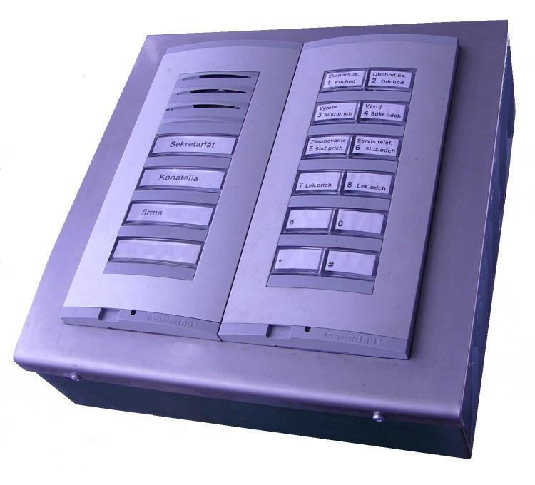
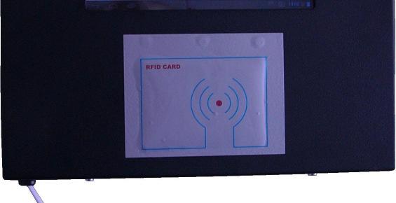
4 1. Popis Produkt GSM/Analóg. Vrátnik plne uspokojí vašu komunikačnú potrebu s návštevníkmi pri vchode budovy, podniku alebo vášho domu. Nepotrebujete žiadne káble (pre GSM verziu), len externé napájanie 12 V DC. 1.1 Funkcia ITX GSM/Analóg. vrátnik je zariadenie s týmito rozhraniami: - štvor-pásmový GSM modul pre pripojenie k mobilnej sieti - analógová linka pre pripojenie k pobočkovej ústredni pozn: v súčasnosti dostupná iba DTMF voľba - externá analóg VoIP (SIP) brána - rádio rozhranie v pásme 433 alebo 868 MHz na prenos obrázkov, údajov o dochádzke alebo konfiguráciu zariadenia cez externý rádio/ethernet prevodník pozn: pásmo rádia je výrobne nastavené, je možné voliť iba kanály - USB V2.0 (1.5 alebo 12 Mbps) rozhranie pre konfiguráciu zariadenia - čítačka bezkontaktných Mifare kariet (ISO-14443A) pozn.: aktívna zóna je medzi tlačidlami 15, Využitie GSM/Analóg. vrátnik môže byť využitý na: - hlasovú komunikáciu medzi užívateľom a návštevníkom volaním z GSM vrátnika na mobilný telefón, pevnú linku alebo PbÚ - hovor môže byť uskutočnený cez GSM alebo analógovú linku alebo VoIP (SIP) - pri volaní cez GSM GSM je možná dvojstupňová voľba s dtmf voľbou pri volaní účastníka pobočkovej ústredne ( priamy prístup do systému - DISA ) - z bezpečnostných dôvodov (ak ethernet je mimo budovy) je použitá externá brána analóg (FXS) - VoIP (SIP) k vrátniku je pripojená analógovou linkou - otváranie dverí (2 relé pre otváranie 2 elektrických zámkov dverí): - po prijatí prednastaveného dtmf kódu pre hlasovú komunikáciu - volaním vrátnika zo zadaného čísla mobilného telefónu - po zadaní prístupového kódu použitím tlačidiel vrátnika - rádiovým diaľkovým ovládačom - po zoskenovaní zadaných RFID Mifare bezkontaktných kariet - softwarovou aplikáciou v mobilnom telefóne s OS Android cez WiFi - automatickou kontrolou externej brány (otváranie, zatváranie) externým infračerveným skenerom - evidenciu dochádzky zamestnancov - po zadaní prístupového kódu stlačením tlačidiel vrátnika a tlačidla typu dochádzky (príchod, odchod, atď...) - po zoskenovaní zadaných RFID Mifare bezkontaktných kariet a stlačení tlačidla typu dochádzky


5 - volaním vrátnika zo zadaného čísla mobilného telefónu a stlačením tlačidla typu dochádzky - po stlačení programovateľného tlačidla na rádiovom diaľkovom ovládači - softwarovou aplikáciou v mobilnom telefóne s OS Android cez WiFi - kontrolu návštevníkom použitím zabudovanej kamery - diaľkovú kontrolu kontaktu kontrola relé cez SMS - signalizáciu alarmu - po zosnímaní zapnutia kontaktu Prevodník USB/GSM INTERNET TCP/IP SERVER MOBILNÁ SIEŤ GSM/Analóg. vrátnik PbÚ Budova 434/868 MHz 434/868 MHz REPEATER Prevodník Radio/Ethernet LAN SERVER RFID USB FXS Dvere/Vchod


6 Budova USB MOBILNÁ SIEŤ 434/868 MHz RFID INFRA RED
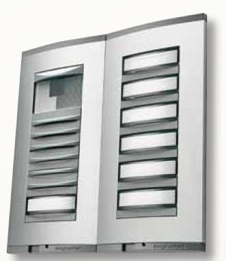
7 2. Hardwarová konfigurácia GSM / ANALÓG. VRÁTNIK štvorpásmový GSM modul SIM 900D (850/900/1800/1900 MHz) integrovaná anténa, možnosť pripojenia externej antény (SMA konektor) držiak SIM karty integrovaný mikrofón, reproduktor a zosilňovač maximálna kapacita 16 tlačidiel (4 tlačidlá základného modulu je možné rozšíriť prídavným modulom s 12 tlačidlami druhá krabička) EEPROM pamäť pre konfiguráciu dát zariadenia (dynamická veľkosť dátových tabuliek) 2 x relé s konfigurovateľnou funkciou 1 x senzor zatvorených dverí alebo kontaktový senzor alarmu USB V2.0 rozhranie pre konfiguráciu zariadenia hodiny reálneho času so záložnou batériou (v GSM verzii) zvuková signalizácia stlačenia tlačidiel, skenovania karty a iných funkcií LED pre podsvietenie tlačidiel (návštevné karty), kamera Externé napájanie 12V DC, 2A voliteľné: analógová linka pre pripojenie k pobočkovej ústredni LION batéria pre zálohovanie zariadenia kamera pre prenos statických obrázkov čítačka Mifare bezkontaktných kariet ISO-14443A automatický ohrev dosky plošného spoja v prípade inštalácie v chladnom prostredí radio v pásme 433 alebo 868 MHz externý prevodník rádio/10bt Ethernet na prenos fotiek, údajov o dochádzke alebo diaľkový prístup diaľkový rádiový ovládač v pásme 433 alebo 868 MHz so 4 programovateľnými tlačidlami pre otváranie/zatváranie dveríalebo evidenciu dochádzky
8 3. Vlastnosti 3.1 Hlasová komunikácia Vrátnik umožňuje hlasovú komunikáciu volaním prostredníctvom mobilnej siete na mobilný telefón alebo PbÚ. Dostupná je aj dvojstupňová voľba, t.z. potom ako ústredňa s GSM rozhraním prijme hovor, zariadenia volí prednastavené číslo účastníka cez dtmf voľbu (DISA). Ďalšia možnosť hlasovej komunikácie je volaním cez analógovú linku pripojenú k PbÚ. Každé zo 16 tlačidiel môže mať naprogramované špecifické číslo (max. 14 číslic) alebo skupinu čísiel (max. 3 čísla). Pre každé číslo je nastavený spôsob akým je hovor uskutočnený - cez GSM sieť, analógovú linku, dvojstupňovú voľbu cez GSM alebo mobility extension. V prípade dvojstupňovej voľby, fixne zadané PbÚ GSM číslo sa volí ako prvé. Je možný preliv medzi skupinami. Systém umožňuje naprogramovať dve tabuľka pre tlačidlá pre denný a pre nočný režim to znamená, že k dispozícii je 16 tabuliek pre denný a 16 tabuliek pre nočný režim. Prepínanie medzi denným a nočným režimom je automatické (na základe nastaveného času) alebo manuálne (po zadaní kódu). Nočný režim je signalizovaný meniacim sa stavom LED (1 sekundu svieti, 1 sekundu nesvieti) in 1 min intervals. Je možné zadať dve časové pásma. Next feature is mobility extension function. It is possible to set calling group with two numbers. One for analogue line (PbX number) and second for GSM network (mobile phone number). After the pushbuttons (with this group programmed) is pressed, system make a call trough these interfaces in the same time. First pick up answer the call from device and second one is cancelled. System does not dial the programmed number automatically after pressing the pushbutton, but waits the specified time whether next pushbutton will be pressed and only then it evaluates the code. The reason is that pushbuttons can be use as numeric keypad for entering the code. Each code (max 5 digits) must be ended by *. If only one pushbutton was pressed and specified time expires, system dials the number. If called subscriber is busy, then, if pushbutton has the group of number programmed, another number is dialed. The same procedure is executed if called party does not answer the call in preset time - that means next number from group of numbers is dialed. Each pushbutton press is signalized by acoustic signal. For analog line, the call release can not be reliably evaluated and therefore the call is ended either if preset max. time expires or door is opened or dtmf code representing the call end is received. The door is opened, meaning relay 1 or 2 is switched on, after receiving the set dtmf code from called party. When dial is initialized next pressing of pushbutton is ignored. The call can be sttopped by twice speed pressing of any pushbutton. Max. call duration is timed. Call time overflow is signalized 4 seconds before end by short beep (500ms). Call can be prolongated by 20 seconds if any pushbutton is pressed.system can to call next 100 numbers (*00,,*99) by using Tabuľka of speed dial and pushbuttons as numeric keypad. In this case user name Tabuľka (without pushbuttons) is necessary with gsm door entry station.
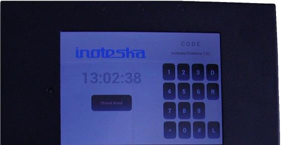
9 In the next device status the pushbuttons have different function, device is waiting for entering attendance type. This state is acoustic signalized. Each pushbutton can has set one of attendance type. 3.2 Door opening Vrátnik umožňuje otvorenie dverí (t.j. zopnutie relé1 alebo relé2) po: - prijatí prednastaveného DTMF kódu zo strany volaného - zadaní kódu (max. 5 číslic) použitím tlačidiel zariadenia (kód je ukončený znakom * ) - stlačení prednastaveného externého tlačidla (jedného zo 16 tlačidiel zariadenia, napr. na vnútornej strane dverí) - prečítaní pred-programovanej bezkontaktnej Mifare karty - prijatí hovoru zo zadaného mobilného telefónu (CLIP číslo) - prijatí platného kódu z diaľkového rádiového ovládača - po prijatí platného príkazu z rádio Ethernet prevodníka (je generovaný z mobilného telefónu s OS Android cez WiFi a WiFi- Ethernet switchu) Pre-programmed relay is switched on for set time. It can be switched off sooner, when door is open and if door open sensing mode is used. Device enables gate remote control (car entry) using relay1, relay2 and contact sensor. In this mode, relay1 opens the gate and relay2 closes the gate. There are two ways of control. It is possible to open and close the gate (switch on relay1 or relay2) using radio remote control in band 433 or 868 MHz with 4 programmable pushbuttons (if GSM door entry phone station is embedded with radio interface). Another option is to open the gate by calling from preset mobile phone. Gate can be closed (relay2 is switched on) after connection of external infrared sensor to device sensor which is used to detect the car passing through the gate. Gate can be closed automatically also when radio remote control is used. 3.3 Attendance evidence Vrátnik umožňuje aj evidenciu dochádzky po: - zadaní kódu (max. 5-miestneho) použitím tlačidiel zariadenia - prečítaní pred-programovanej bezkontaktnej Mifare karty - prijatí hovoru zo zadaného mobilného telefónu (CLIP číslo) - prijatí platného kódu z diaľkového rádiového ovládača zmena firmware lokálne alebo diaľkovo diagnostika zariadenia jednoduchá inštalácia Device can be also used as attendance system. It is possible to set the codes, contactless cards or mobile phones whose attendance must be recorded. Then, after identification, system waits for pressing the appropriate attendance type pushbutton. Pushbuttons have multiple functions. Its meaning depends on the state when the pushbutton is pressed. For attendance evidence, following meaning of pushbuttons can be programmed: 0 - attendance departure
10 1 - attendance arrival 2 - interruption departure 3 - interruption arrival 4 - business departure 5 - business arrival 6 - doctor departure 7 - doctor arrival or other customer codes (max. total number of types is 12). Only after pressing the pushbutton, if it is programmed as arrival, the particular relay is switched on and door is opened. Each code, contactless card and mobile phone number has the employee registration number set. This number together with attendance type, date and time, is sent by radio interface and radio or RS485 / Ethernet converter to server where the data is saved and processed. Resulting from this, attendance evidence for one employee can be carried out in several ways. Special application software on server is necessary for function of receive and save the attendance data. Attendance evidence and door opening can be performed also using the radio remote control with 4 programmable pushbuttons of attendance type. It is the most speed way. The door is opened and no next pushbuttons need to be pressed. Another possibility for attendance evidence is use software application in mobile phone with Android by WiFi. 3.4 Persons control If device is equipped with integrated color camera, then it is possible to control the visitors at the door entrance by sending the static images in JPEG format over radio interface and external radio/ethernet converter to server. To display the images on PC or mobile phone, special application software must be used. After pressing the pushbutton, illumination leds are activated and image transfer starts. Transfer is stopped if person starts to enter the code. Voice call is delayed, device waits the specified time whether next pushbutton is pressed. Image can be transferred automatically if this function is activated for contact switch on evaluation. 3.5 Additional functions Device senses one input contact which can be used for sensing the door opening or as alarm contact. It is possible to set various modes of relay number 2 control: - automatic switch on/off based on time settings (e.g. control of outdoor light) - always switch on when pushbutton is pressed (e.g. for external camera) - always switch on when pushbutton in night mode is pressed - switch on when contact is switched on (e.g. for external alarm) - switch off when door is open - switch on when external gate is being closed Another additional function is switching between day and night modes and switching on the pushbuttons led illumination based on set time. Moreover, it is possible to set automatic device identification after turning on by sending its serial number and mobile phone number to server, over some of above mentioned interfaces.
11 GSM door entry phone station can transmit also various alarm messages, when: - door is open for long time - entrance without identification is observed - incorrect identification, code is recorded - power supply drop-out - contact is switched on It is possible to set which alarm types have to be signalized and then the interface type for each alarm type alert. To send alarm alerts by SMS or calls to mobile numbers, separate Tabuľka of called numbers is programmed. Optional firmware change - locally or remotely. Device diagnostics is also available. 4. Configuration Device can be configured using configuration SW on PC: - locally: - by USB interface - remotely (central): - manually: - over USB / GSM converter by data connection (M2M) to GSM door entry phone station over mobile network - over Internet network using TCP / IP protocol in application client-server, where GSM door entry phone station, after receiving the specified number (using CLIP service) or receiving SMS, activates TCP connection to specified server over mobile network - by SMS sent to GSM door entry phone station - over radio or RS485 / Ethernet converter using TCP / IP protocol in application client - server - setting of programming mode, programming of RFID cards using device pushbuttons! Caution! If USB cable is connected to PC and than the power is on, device is in change firmware state (bootloader is running) and wait some ten seconds. In this state firmware can be changed by using another software in PC. If the remote upgrade firmware by GSM network is unsuccessful only locally way by USB after turn off is able. Configuration SW uses graphic mode. Configurations data can be saved to PC. Configuration SW contains the file with default production configuration. Structure of
12 configuration Tabuľkas is dynamic, that means their size and location in EEPROM memory is variable. Total capacity of configuration data depends on type of EEPROM memory used. Basic type capacity is 8kB and can be increased without need to change PCB. For easier programmed of some parameters (codes, contactless cards,...), e.g. by SMS, configuration SW enables to generate the size of individual Tabuľkas in accordance with customer requirements without obligation to change complete memory content (that is time-consuming process and can not be executed by configuration by SMS, that means the Tabuľka size is not extended automatically after its overload). 4.1 Číslovanie tlačidiel Krabička 1 Krabička 2 Príklad: Ekonomický úsek 1 Príchod Výrobný úsek 3 Príchod-súkrom. Nákupný úsek 5 Príchod-služobne Obchodný úsek 2 Odchod Úsek vývoja 4 Odchod-súkrom. Servisný úsek 6 Odchod-služobne 7 Príchod-lekár 8 Odchod-lekár 9 0
13 * # 5. Structure of configuration data Configuration data consist of following Tabuľkas: 5.1 Tabuľka of production configuration - serial number - production date - device type - hardware configuration - radio band (433 or 868 MHz) 5.2 Tabuľka of basic configuration 0. - waiting time period for between individual presses of pushbuttons - [100 ms] 1. - max. switch-on time of relay 1 - [100 ms] 2. - max. switch-on time of relay 2 - [100 ms] 3. - max. ringing time - waiting for called party answer - [s] 4. - call rerouting time - for group call - [s] 5. - max. door opening time - [s] 6. - max. call duration time - for analog line - [s] 7. - device mode (1..8 = x - parameter number):
14 1. - active sensing of closing the door 2. - day/night mode switching 3. - send image if contact is switched on / automatic gate control 4. - relay 2 switch off when door opening 5. - time switching mode of relay 2 control 6. - always switch off relay 2 when pushbutton is pressed 7. - always switch on relay 2 when pushbutton in night mode is pressed 8. - always switch on relay 2 when contact is switched on 8. - device identification (x - parameter number): 1. active connection to server over IP 2. send door status to server 3. - send attendance data to server over radio 4. - send attendance data to server over RS232/RS device identification after turn on over IP 6. - device identification after turn on over data call 7. - device identification after turn on over SMS 8. - active connection to server over IP 9. - type of mode (day / night) in Sunday and Saturday (x - parameter number): 1. - night mode 2. - fixed setting (if not - setting is by switching time) relay 2 switch-on time - hour : minute relay 2 switch-off time - hour : minute led pushbuttons turn-on time zone1 - hour : minute led pushbuttons turn-off time zone1 - hour : minute led pushbuttons turn-on time zone2 - hour : minute led pushbuttons turn-off time zone2 - hour : minute day mode switching time zone1 - hour : minute night mode switching time zone1 - hour : minute day mode switching time zone2 - hour : minute night mode switching time zone2 - hour : minute server IP address server port IP provider APN - for internet access own telephone GSM number GSM tel. number of PbX (two - step dial) GSM tel. number of server (CLIP) - IP connection to server after incoming call GSM tel. number of server - for data call to server 5.3 Tabuľka of GSM parameters 0. - speaker volume (value: 0-100) 1. - ringing volume (value: 0-4) 2. - microphone sensitivity (value: 0-15) 3. - echo suppression (value: 0 8) 4. - selective echo suppression (value: 0 6) 5. - echo suppression on/off SIM pin code number of digits of identification prefix in international format
15 5.4 Tabuľka of analogue line parameters 0. type of tone detection (ringing, call, ) 1. - level of DTMF signals (value: 0-12 = -16dBm.. -4dBm) 2. - DTMF-settings (preempahsis and confidence level) 3. - softclip-settings, noise monitoring 4. - hands free receive endgain level 5. - hands free switching characteristic 6. - level of transmitted audio signal 7. - level of received audio signal 8. line voltage, line loss compensation setting 5.5 Tabuľka of radio parameters 0. - object number - domain - for radio packets 1. - device address - for radio packets 2. - nominal frequency (channel - value: 0-7) 3. - data baud rate (value: 0-13 = 35kbps..100kbps step 5kbps) 4. - radio output power (value: 0-7 = -1dB..+20dB step 3dB) 5.6 Tabuľka of RFID parameters 0. - contactless card reader mode (only ISO-14443A available now) 5.7 Tabuľka of camera parameters 0. - parameter of camera image resolution (value: 1,3,5,7) 1-80 x x x x Tabuľka of pushbutton codes 1. - code - max. 5 digits 2. - parameters 1. - switch on relay switch on relay send registration number 4. - attendance evidence 5. - contactless RFID cards programming 6. - day/night mode switching reset RFID 3. - employee registration number ( )
16 5.9 Tabuľka of numbers for 16 pushbuttons - day mode 1. - tel. number (max. 14 digits) or group number or mobility extension group 2. - parameters + attendance type value 1. - switch on relay switch on relay two-step dial 4. - call over analog line - attendance type (value: 0-13, 15 - no attendance access) 0 - attendance departure 1 - attendance arrival 2 - interruption departure 3 - interruption arrival 4 - business departure 5 - business arrival 6 - doctor departure 7 - doctor arrival 8,9,A.B.C - customer codes (9,B = arrival) D - door opening F - unused 5.10 Tabuľka of numbers for 16 pushbuttons - night mode The same as for day mode Tabuľka of calling groups - day mode 1. - max. 3 numbers (one number max. 14 digits) - number can also represent number of overflow group 2. - parameters for each number 3. - two-step dial for GSM call 4. - call over analog line 5.12 Tabuľka of calling groups - night mode The same as for day mode Tabuľka of identification (CLIP)-incoming call over GSM for relay switch on 1. - CLIP - max. 14 digits 2. - parameters 1. - switch on relay switch on relay send registration number 4. - attendance evidence 3. - employee registration number ( )
17 5.14 Tabuľka of identification (CLIP) - data call or SMS from GSM - configuration enabled 1. - CLIP - max. 14 digits 2. - parameters 1. - authorization - numbers change 2. - authorization - all parameters change 5.15 Tabuľka of DTMF codes 1. - code - max. 3 digits 2. - parameters 1. - switch on relay switch on relay connection release - on hook 4. - prolong the call by 20 sec 5.16 Tabuľka of valid RFID codes (contactless cards) 1. - RFID UID - max.14 digits 2. - parameters 1. - switch on relay switch on relay send registration number 4. - attendance evidence 3. - employee registration number ( ) 5.17 Tabuľka of alarm alerts 1. - alarm type 0. - door opened for long time 1. - entrance without identification 2. - incorrect identification, code 3. - power supply drop-out 4. - contact switched on 5. - SIM is removed 2. - interface type for each alarm type sending (TCP/IP, M2M, radio, SMS, voice call) or specified alarm type is not signalized 3. - text for alarm message 5.18 Tabuľka of GSM number for alarm alerts 1. - GSM tel. number - max. 14 digits 5.19 Tabuľka of valid employee registration number for radio remote access 1. - employee registration number ( )
18 5.20 Tabuľka of direct speed dial (*00.. *99) 1. - tel. number or group number - max. 14 digits 2. - parameters 1. - two-step dial 2. - call over analog line 3. - code (index) - 2 digits 5.21 Tabuľka of password for configuration 6. Device configuration over SMS Each SMS must begin with character "/". Then number of function and ",". All parameters, values are separated by ",". Other characters which are used: "#","*", ">" and ":". Value and parameters, using SMS functions, correspond to the particular Tabuľka in configuration data structure. Parameter can be one of these parameters. Following functions are available by SMS: FUNC1 - change of pushbutton number - day mode /1, pushbutton number (1..16), tel. number or #group number, *parameters note: parameters = attendance type value "," parameter for example: /1,16, ,*01 (set number for pushbutton 16 in day mode, attendance departure, switch on relay 1) FUNC2 - change of pushbutton number - night mode /2, pushbutton number (1..16), tel. number or #group number, *parameters note: parameters = attendance type value "," parameter
19 for example: /2,8,#4 (set group 4 for pushbutton 8 in night mode) FUNC3 - change of numbers of group - day mode /3, group number, tel. number, *parameter, tel. number, *parameter,...(max. 3) note: tel. number can be also # and number of overflow group for example: /3,4, ,201,*4, (set two numbers for group 4 in day mode: and call over analog line) FUNC4 - change of numbers of group - night mode /4, group number, tel. number, *parameter, tel. number, *parameter,...(max. 3) note: tel. number can be also #number of overflow group FUNC5 - change of code of pushbuttons /5, old code, new code (max. 5), *parameter, #employee registration number note: if new one is blank -> only old one is deleted FUNC6 - setting of new code of pushbuttons /6, code (max. 5), *parameter, #employee registration number FUNC7 - change of CLIP (in Tabuľka of identification - call from GSM for relay switch on) /7, old clip, new clip, *parameter, #employee registration number note: if new clip is blank -> only old one is deleted FUNC8 - setting of new CLIP (in Tabuľka of identification - call from GSM for relay switch on) /8, clip, *parameter, #employee registration number FUNC9 - CLIP for device configuration /9, old clip, new clip, *parameter note: if new clip is blank -> only old one is deleted FUNC10 - setting of new CLIP for device configuration /10, clip, *parameter FUNC11 - deleting of RFID code for employee registration number /11, #employee registration number FUNC12 - setting of RFID code for employee registration number /12, #employee registration number, *parameter FUNC13 - setting of general parameters - Tabuľka of basic configuration /13, number of parameter (0..20), #value (0..255) or >value ( ) or *parameter or :time (hour, minute e.g. :hhmm) FUNC14 - device reset /14

20 FUNC15 - connection to server (device will connect to server by TCP/IP protocol) /15 FUNC16 - relay 2 control /16, 1 (switch on) or 0 (switch off) FUNC17 - radio reset /17 FUNC18 - rfid reset /18 FUNC19 - set night mode /19 FUNC20 - set day mode /20 7. Programming of contactless Mifare RFID cards Contactless cards can be programmed to the device in programming mode. This mode is set by entering the valid pushbutton code or by option in configuration software and is signalized by flashing of pushbuttons leds. In programming mode, the card is attached to the device. Scanning the unique UID number is signalized by acoustic signal. In this state, it is possible to set the parameters and employee
21 registration number for this card. As mentioned above, pushbuttons have multiple meaning. Expanded case consists of 12 pushbuttons which, in this mode, represent a numeric keyboard that means digits 0 to 9 and characters "*", "#". After pressing *, list of parameters in accordance with above described Tabuľka is entered. After pressing #, employee registration number is entered. If other than numeric pushbutton is pressed, data is saved to the EEPROM memory (if there is free Tabuľka capacity). If no card is scanned and other than numeric pushbutton is pressed, programming mode is exited. Another option how to set the registration numbers or parameters, after first programming of cards, is to edit this data using configuration software, in the same order as individual cards were scanned. This procedure is necessary if expanded case with 12 pushbuttons is not used. Other changes of contactless cards can be performed only using configuration SW or by SMS according to employee registration number. Note: active area is between pushbuttons number 15, 16 Easier way of programming is using external reader. It is connected to PC via USB. Operating system detects it as HID USB keyboard. In configuration SW window Settings of RFID cards, if cursor is set to UID code, this code is automatically scanned after card is attached to USB RFID reader. 8. Configuration software

22 9. Firmware upgrade - locally:
23 - by USB interface HIDBootLoader.exe has to be use on PC After turn on the device and USB is connected to PC, bootloader is running, (short time) and firmware can to be changed. In this state it is not possible to configure the device only after time is overflow. - by Ethernet / RS232 (RS485) converter (in power supply ITZ ) - remotely (central): - over USB / GSM converter by data connection (M2M) to GSM door entry phone station over mobile network by using configuration software If remote software upgrade was not successful, next attempt can be performed only locally (by USB) after switching the device off and on. If PC is connected to device by USB, then each time the device is turned on, it is in status upgrade firmware. To configure the device only, connect PC to device after it is turned on. 10. Installation and setting up

24 1. Unpack and open the box. Then take out PCB. Beware of mechanical damage and electrostatic discharge. 2. After mechanical mounting of unit, connect the cables: power supply +12V DC, relay contacts, contact sensors, expander box with 12 pushbuttons. Before connecting the power supply, as well as each inserting/removing SIM card, jumpers PR6 (battery disconnecting/connecting) and PR8 (12V power supply disconnecting/connecting) must be disconnected. 3. Insert and secure PCB. 4. Insert SIM card.
25 5. Check feeding voltage tolerance and polarity. 6. Connect jumper PR8 or PR6. 7. Connect PC by USB. 8. Run configuration software and configure the device. Almost all the parameters can be set using configuration software. The only mechanical element, which can be changed, is trimmer R12. It is used to suppress the acoustic restraint when communication is performed over analog line (FXS). 9. Check the proper device function using basic case pushbuttons. 10. Disconnect PC and mount the cover with pushbuttons. 11. Diagnostics It is possible to set automatic device identification to centre after its turning on (power supply connection) by sending its serial number and mobile phone number to server, over pre-set interface. Device enables the diagnostics - that means by USB interface to find out the statuses from main memory, print out transmitted and received packets of each interface. This can be performed only after personnel training or consultation with producer. 12. Technical parameters
26 12.1 Electrical parameters Power supply: Battery: 12VDC ± 2V, 2A Lion polymer 3.7V, 800mAh mah Max. consumption: Relay: GSM: Analog: RFID: - max. switching current - 2A - max. switching voltage - 250VAC / 220VDC - max. switching power - 62,5VA / 30W - Quad-Band 850/900/1800/1900 MHz - GPRS multi-slot class 10/8 - GPRS mobile station class B - compliant to GSM phase 2/2+ - class 4 850/900 MHz) - class /1900 MHz) - line current - from 15mA to 100mA (down to 5mA with reduced performance) - voltage on line while off hook (VA characteristics): 3.5V or 4.5V - impedance of line termination: complex or 600 Ohm - bandwidth: Hz - valid dtmf input signal levels: min= -31dBm, max= 2dBm - DTMF twist = High Tone/Low Tone: min= -10dB, max= 10dB - DTMF frequency detect bandwidth: ± 2.2% - DTMF detect response time: 40ms - DTMF pause length detected: 30ms MHz HF RFID reader - ISO 14443A and B (in this firmware only 14443A) - output power up to 500mW Radio: - frequency range MHz

27 Camera: GSM / ANALÓG. VRÁTNIK - sensitivity: -121 dbm - output power range: +20 dbm max - power consumption: ma receive dbm transmit dbm transmit - data rate: to 256 kbps - FSK, GFSK, and OOK modulation - JPEG format - resolution: - 80 x x x x Mechanical parameters Material: anodized aluminium Dimensions: IP54 protection Weight: x g H = 207mm L = 99mm D = 28mm (one case) 13. Operating environment Temperature: -20 to +50 C
28 Humidity: 10% / 80% at 30 C GSM / ANALÓG. VRÁTNIK 14. HW configuration and ordering DEPS - G Ax I Rx C B T H E Mx Door entry phone station GSM Analog x=6 (600 Ohm) x= 9 (complex) RFID Radio x=4 (433 MHz) x=8 (868MHz) Camera Lion battery Battery for real time Heating PCB Expander box with 12 buttons Configuration memory capacity x=8 or 32 or 64 kb (default 8kB) 15. Converter Ethernet / Radio

29 Ethernet / Radio converter is used for transmission of attendance data, images and device configuration over radio network in band 433 or 868 MHz. It uses TCP/IP protocol in application client - server. With another firmware, it can also be used as radio repeater. To process attendance data and images from camera, external application software is used Technical parameters Ethernet: 10 Base T, IEEE Power over Ethernet IEEE 802.3af or external power supply VDC, 200 ma Radio: MHz, FSK, GFSK, and OOK modulation, max +20 dbm Internal or external antenna (SMA connector) Dimensions: 90x65x22 mm 15.2 Configuration Ethernet / Radio converter is configured over Telnet protocol by PC or by configuration software as external device function. Default settings: IP address: Mask: Login: admin Password: inoteska It is possible to set: "LOGIN : " "PASSWORD : " "RADIO DOMAIN (0..99) : " "RADIO BAND (19 OR 43 e.g. 433 or 868) : " "RADIO BAUD RATE (0..13) : " "RADIO OUTPUT POWER (0..7) : " "RADIO CHANNEL (0..7) : " "IP ADDRESS : " "SUBNET MASK : "
30 "GATEWAY : " "DNS SERVER : " "SERVER IP ADDRESS : " (*) "SERVER PORT : " (*) "CONFIGURATION PORT : (**) ATTENDAN PORT : (***) GSM / ANALÓG. VRÁTNIK Note: * - remote server parameters for attendance data sending ** - port for configuration door entry phone station *** - port for mobile phone software application! radio parameters have to be same as in the door entry phone station! Firmware can to be changed by using TFTP protocol. After turn on the device or after press X in telnet monitor, bootloader is running (short time), led on RJ45 is blinking and firmware can to be changed. Command line (from command prompt): tftp IP address put (path) prev_eth_radio.hex For example: tftp put C:\prev_eth_radio.hex Default configuration can be set by shorting two pins in connector on PCB before turn on the device (consult this with producer) HW configuration and ordering COER - P E Bx R Converter Ethernet/Radio Power over Ethernet External antenna Radio band x=4 (433 MHz) x=8 (868MHz) Repeater 16. Remote radio control unit

31 Remote radio control unit is used for remote door opening and attendance evidence. It communicates with door entry station over radio network in band 433 or 868 MHz. It has 4 programmable pushbuttons or if one pushbutton is configured as shift, then three others has double function that means max. 6 different codes can be set. Remote radio control unit is programmed by configuration software trough USB adapter. The same domain (object), channel and baud rate has to be set as in GSM door entry station. Remote radio control unit is powered by internal 3V LION battery Technical parameters Battery: 3V CR2032 Radio: MHz, FSK, GFSK, and OOK modulation, max +20 dbm 4 rubber buttons Dimensions: 52x36x13 mm 16.2 Configuration Remote radio control unit can be configured by external USB adapter using configuration software as external device function.. It is possible to set: "RADIO DOMAIN (0..99) : " "DEVICE ADRESS (1..255) : " "RADIO BAND (19 OR 43 e.g. 433 or 868) : " "RADIO BAUD RATE (0..13) : " "RADIO OUTPUT POWER (0..7) : " "RADIO CHANNEL (0..7) : " "ADDRESS OF DOOR STATION FOR BUTTON 1 (1..255) : " "ADDRESS OF DOOR STATION FOR BUTTON 2 (1..255) : " "ADDRESS OF DOOR STATION FOR BUTTON 3 (1..255) : " "ADDRESS OF DOOR STATION FOR BUTTON 4 (1..255) : " "1. FUNCTION FOR BUTTON 1 : " "1. FUNCTION FOR BUTTON 2 : " "1. FUNCTION FOR BUTTON 3 : " "1. FUNCTION FOR BUTTON 4 : " "2. FUNCTION FOR BUTTON 1 : " "2. FUNCTION FOR BUTTON 2 : " "2. FUNCTION FOR BUTTON 3 : " "2. FUNCTION FOR BUTTON 4 : "
32 "EMPLOYEE REGISTRATION NUMBER ( ) :" Pushbutton function can be following : Switch on relay 1 Switch on relay 2 shift button attendance evidence (set arrival or departure, ) attendance type: 0 - attendance departure 1 - attendance arrival 2 - interruption departure 3 - interruption arrival 4 - business departure 5 - business arrival 6 - doctor departure 7 - doctor arrival Function, attendance type and employee registration number is transmitted after pressing the pushbutton. Note:radio parameters have to be same as in door entry phone station 16.3 HW configuration and ordering RRCU - Bx Remote radio control unit Radio band x=4 (433 MHz) x=8 (868MHz) 17. Converter USB / GSM (data modem) The door entry phone station with the different firmware can be use as USB / GSM converter for remote configuration a lot of devices trough GSM network. The
33 configuration software allows setting type of connection. In this type of communication data call (M2M) is using but transfer speed is low. 18. Analog / VoIP (SIP) gateway For safety reasons (ethernet is outside of building), external analog (FXS) VoIP (SIP) gateway is used. It is connected to the station by analog line. The configuration depends on type of gateway used. 19. Software application for mobile phone with Android Software Porter is an application in Java. It is designed for mobile phones and it is running under OS Android version 2.1 and higher. Application Porter is used to open

34 the door and to record employee attendance. It is a complementary utility to the product GSM door entry phone station. The application replaces the remote radio control unit used for door entry phone station. Android device must have a WiFi interface. At least 3.2" touch screen is recommended. For connection to attendance evidence server and door entry station WiFi LAN and Ethernet radio converter are used. Description of operation: Application Porter (as Porter) communicates with the device GSM door entry phone station (as Door station) by WiFi network using TCP / IP protocol. Porter can operate only with one Door station at the same time. Total number of Door stations which Porter operates with, is not limited. Basic Porter screen: Screen portrait mode: On the Porter basic screen, there are six buttons for attendance records, two status lines with text listings, Open Door attribute button when using attendance buttons, Settings button, apply button for selection of particular Door station device and Open the door button without the attendance recording. 1. Attendance recording buttons Six basic buttons for attendance recording. By pressing the button, a command is sent to Door station. Door station sends a message to the attendance system. If


35 Door station system uses the electronic door control and the attribute for door opening (Door) is on, then door will be opened after pressing the button Open door. Use of Long button press can be set in Porter Settings. Porter settings allow to set a response for pressing the attendance buttons by either vibration and also by playing the sound. 2. Status lines First status line displays the service availability. Application can be used if Porter is connected to the correct WiFi network with sufficient signal level. After pressing the attendance button and its execution, the description of last executed command is displayed in the first line. Second line displays the name of WiFi network used by Android device and Porter. 3. Settings button Porter settings are divided into the sections: - User user s Personal number is set It's a personal number of employee whoese attendace will be recorded after pressing the attendance recording buttons.
36 - Devices Count of door keepers is set. Number of used devices which Porter currently operates with, is selected on the basic screen - selection of Door station. - Network settings it is necessary to set: IP address for ETH/radio converter, Port used for TCP/IP communication, WiFi Network name in which Porter can be used. It is possible to set Switch off WiFi for automatic disabling of WiFi interface in Android device after closing the Porter application. - Tones and Sounds - the response for pressing the buttons is set: Vibrate 1 (2) - vibration response, Tone 1 (2) - sound is played. - Buttons use of long button press s is set 4. Door atribute button when using attendance buttons If Door station system uses the function of electronic door control, it is possible to enable/disable the attribute of door opening while using attendance buttons. 5. Door station selection button Possibility to select Door station from list of stations which Porter communicates with. 6. Open door button After pressing the button, door is opened without recording the employee arrival or departure. It is used e.g. to allow the visitors to access the building. Installation: Load the latest version of Porter.APK and istall it to Anroid OS using standard procedure. After istallation, icon named Porter is displayed among the applications. 20. Power supply ITZ
37 Power supply ITZ is recommended for power supply of GSM, analog door entry phone station. Primary voltage : 230V, 30VA Secondary voltage: V AC for door lock V DC 2A for door entry station power supply ITZ is equipped with: 1. connector RJ45 for connection of analog line and RS232 or RS485 in door phone station. 2. connector RJ11 for connection of analog line to PbX or to FXS/VoIP gateway. 3. Ethernet 10BT connector RJ45 converting RS232/RS485 to Ethernet. It can be used and configured as Ethernet / radio converter. 4. Relay for door lock control. 5. connector for power, relay and electric lock connection. 21. Warranty conditions
38 The product was shop-checked. The producer guarantees that this product will keep the features described in these operating instructions in the course of guarantee provided that the user will be handled with it as described in the operating manual. The guarantee will be extended by period of possible guarantee repair. When claiming in guarantee period please contact your dealer. The producer only will make the guarantee repairs. Attach the description of claim reason, proof of purchase and your exact address to the product. The guarantee does not include: * mechanical, thermal, chemical and other damages caused by user s activities * defects caused by natural disasters * defects caused by repair or changes carried out by user or other unauthorized person * willful damage of product * incorrect use of product caused by other use than specified in operating manual (e.g. installation, programming) * damages caused during product transport to customer and from supplier
GPRS-T2. GPRS/SMS Reporting Module. SATEL sp. z o.o. ul. Schuberta Gdańsk POLAND tel
 GPRS/SMS Reporting Module GPRS-T2 Program version 1.0 gprs-t2_en 11/08 SATEL sp. z o.o. ul. Schuberta 79 80-172 Gdańsk POLAND tel. + 48 58 320 94 00 info@satel.pl www.satel.pl WARNINGS The module should
Lynx. RoIP Gateway DISPATCH LYNX MOBILE. Optional serial ports provide remote control of radio configuration over the VoIP network.
 LYNX MOBILE Lynx DISPATCH RoIP TM SYSTEM Gateway LYNX TM ROIP GATEWAY OVERVIEW The Lynx system provides Radio over IP (RoIP) communications interoperability between radio base stations and VoIP networked
Hytera DMR Conventional Series
 Hytera DMR Conventional Series SIP Phone Gateway to Simultaneous Calls Application Notes Document version: 3.0 Date: 02-2015 Copyright Information Hytera is the trademark or registered trademark of Hytera
QUICK GUIDE for multiguard Light. Installation
 QUICK GUIDE for multiguard Light Installation 1. Prepare a SIM card so that the PIN code is 1234 or is deactivated. Mount the card in the unit. The unit has now 1234 as password or runs without a password.
Four Simple Steps to Get Started
 Four Simple Steps to Get Started This guide provides an overview of the important features and instructions for how to set up and operate the Spectra Precision SP90m GNSS receiver. 1. Unpack and check
SOUTHERN AVIONICS COMPANY. SE125 Transmitter. SE125 Transmitter 1-1
 1-1 1 Introduction The SE Series transmitters are computer controlled systems designed around an embedded microprocessor. These systems are capable of remote monitoring and maintenance via Ethernet (optional).
ASTRO/Intercom System
 ASTRO/Intercom System SISTEMA QUALITÀ CERTIFICATO ISO 9001 ISO 9001 CERTIFIED SYSTEM QUALITY F I T R E S.p.A. 20142 MILANO ITALIA via Valsolda, 15 tel.: +39.02.8959.01 fax: +39.02.8959.0400 e-mail: fitre@fitre.it
TSA 6000 System Features Summary
 2006-03-01 1. TSA 6000 Introduction... 2 1.1 TSA 6000 Overview... 2 1.2 TSA 6000 Base System... 2 1.3 TSA 6000 Software Options... 2 1.4 TSA 6000 Hardware Options... 2 2. TSA 6000 Hardware... 3 2.1 Signal
Above All. The most sophisticated unit for tracking containers in real time for security and management.
 * The most sophisticated unit for tracking containers in real time for security and management. The French comedian Pierre Dac once said, To see into the distance, you simply need to get closer. That applies
INSTRUCTION MANUAL IP REMOTE CONTROL SOFTWARE RS-BA1
 INSTRUCTION MANUAL IP REMOTE CONTROL SOFTWARE RS-BA FOREWORD Thank you for purchasing the RS-BA. The RS-BA is designed to remotely control an Icom radio through a network. This instruction manual contains
"Terminal RG-1000" Customer Programming Software. User Guide. August 2016 R4.3
 "Terminal RG-1000" Customer Programming Software User Guide August 2016 R4.3 Table of Contents Table of Contents Introduction 2 3 1.1 Software installation 3 1.2 Connecting the RG-1000 GATEWAYs to the
P2P 2 YEAR PL-VDIO-05. Smartphone Connect IP VIDEO DOOR PHONE QUICK START GUIDE 7 VIDEO DOOR PHONE SYSTEM WITH SMARTPHONE CONNECT
 PL-VDIO-05 IP VIDEO DOOR PHONE QUICK START GUIDE Smartphone Connect 2 YEAR RR T SERVICES WA P2P Y Receive calls, remote monitor and remote unlock with your smart phone AN 7 VIDEO DOOR PHONE SYSTEM WITH
A-MUX 32P DOCUMENTATION
 A-MUX 32P DOCUMENTATION CONTENTS 1. General description 2 2. Applications 3 3. A-MUX specifications 5 4. Connectors of E1 and Ethernet interface 7 5. Connectors of analog interfaces 8 6. Modules FXS, FXO,
SpeedTouch 190. Setup and User s Guide. SIP Gateway. Release R1.0
 SpeedTouch 190 SIP Gateway Setup and User s Guide Release R1.0 SpeedTouch 190 Setup and User s Guide Release R1.0 Status v1.0 Reference E-DOC-CTC-20040401-0004 Short Title Setup and User s Guide ST190
GSM-4 (program version 4.02)
") COMMUNICATION MODULE GSM-4 (program version 4.02) OPERATING INSTRUCTION GDAŃSK, POLAND gsm4_e 11/03 WARNING For safety reasons, the module should only be installed by qualified personnel. In order to avoid
COMMUNICATION MODULE GSM-4 (program version 4.02) OPERATING INSTRUCTION GDAŃSK, POLAND gsm4_e 11/03 WARNING For safety reasons, the module should only be installed by qualified personnel. In order to avoid
TMR880i technical details
 SCS / Terminals Jan 2013 1(8) TMR880i technical details SCS / Terminals Jan 2013 2(8) TETRA Terminals from CASSIDIAN fulfill the following specifications for TETRA radio equipment in the temperature range
----STAR S86 GPS Receiver. User Guide. SOUTH CO., Ltd.
 ----STAR S86 GPS Receiver User Guide SOUTH CO., Ltd. www.southsurveying.com Sales@SOUTHsurveying.com 2 CONTENTS Chapter 1 Introduction... 1 STAR S86 GPS - System Summary... 1 Technical Specification...
GPS Vehicle tracker. GT06F User Manual (Version V1.1)
") GPS Vehicle tracker GT06F User Manual (Version V1.1) This user manual has been specially designed to guide you through the functions and features of your GPS vehicle tracker. 1.Start Guide 1.1 Accessories
GPS Vehicle tracker GT06F User Manual (Version V1.1) This user manual has been specially designed to guide you through the functions and features of your GPS vehicle tracker. 1.Start Guide 1.1 Accessories
Interface Genius Modem Instruction Manual v1.2.4
 Interface Genius Modem Instruction Manual v1.2.4 Interface Genius Modem is a USB / LAN controlled SO2R radio interface remote radio modem. It is designed to be controlled by a Windows application, and
GPS&GPRS TRACKING SYSTEM GT3100
 GPS&GPRS TRACKING SYSTEM GT3100 OPERATION/INSTALLER MANUAL REV: 2.0 (GT3100-special, V1.51, GT500-SIM340.C1) I. INTRODUCTION PORTMAN GPS GPRS tracking system GT3100 utilize the GPS tracking function and
IX Series 2. Description. IX Series 2 System Features
 IX Series 2 Description The IX Series 2 is a network-based video intercom platform. It is designed for access entry, internal communication, audio paging, and emergency calling applications. The IX Series
ADDENDUM 1. Bid# , Radio Interoperability System for the Sheriff's Office
 County of El Paso Purchasing Department 500 East San Antonio, Room 500 El Paso, Texas 79901 (915) 546-2048 / Fax: (915) 546-8180 ADDENDUM 1 To: From: All Interested Proposers Claudia Sepulveda, Bid Clerk/Buyer
This is by far the most ideal method, but poses some logistical problems:
 NXU to Help Migrate to New Radio System Purpose This Application Note will describe a method at which NXU Network extension Units can aid in the migration from a legacy radio system to a new, or different
GPRS-A. Universal monitoring module. Firmware version 1.00 gprs-a_en 04/18
 GPRS-A Universal monitoring module Firmware version 1.00 gprs-a_en 04/18 SATEL sp. z o.o. ul. Budowlanych 66 80-298 Gdańsk POLAND tel. +48 58 320 94 00 www.satel.eu WARNINGS The module should be installed
TABLE OF CONTENTS. Keypad Programming Manual 1
 TABLE OF CONTENTS How To Program Radios...2 Keypad Programming...2 A. Navigation...3 1. Group Parameters (CH 00)...4 2. Channel Parameters (CH 01 - CH20)...4 3. Global Parameters (GRP 00)...5 B. Group
RF Wireless Serial Device Server
 RF-SDS RF Wireless Serial Device Server The RF-SDS subassembly is a radio transceiver acting as a Serial Device Server, which externally connects a remote serial RF transceiver to an Ethernet network (TCP/IP).
TRBOnet Enterprise. IP Site Connect. Deployment Guide. Internet. US Office Neocom Software Jog Road, Suite 202 Delray Beach, FL 33446, USA
 TRBOnet Enterprise IP Site Connect Deployment Guide World HQ Neocom Software 8th Line 29, Vasilyevsky Island St. Petersburg, 199004, Russia US Office Neocom Software 15200 Jog Road, Suite 202 Delray Beach,
TRBOnet Enterprise. Extended Range Direct Mode. Deployment Guide. Internet
 TRBOnet Enterprise Extended Range Direct Mode Deployment Guide World HQ Neocom Software 8th Line 29, Vasilyevsky Island St. Petersburg, 199004, Russia US Office Neocom Software 15200 Jog Road, Suite 202
Version 8.8 Linked Capacity Plus. Configuration Guide
 Version 8.8 Linked Capacity Plus February 2016 Table of Contents Table of Contents Linked Capacity Plus MOTOTRBO Repeater Programming 2 4 MOTOTRBO Radio Programming 14 MNIS and DDMS Client Configuration
Video Intercom System Introduction
 Video Intercom System Introduction CONTENTS Application Products Installation Operation Video Intercom System Service for residential area, Provide two-way video/audio call between visitors and residents,
TRBOnet Enterprise. Capacity Plus. Deployment Guide. Internet. US Office Neocom Software Jog Road, Suite 202 Delray Beach, FL 33446, USA
 TRBOnet Enterprise Capacity Plus Deployment Guide World HQ Neocom Software 8th Line 29, Vasilyevsky Island St. Petersburg, 199004, Russia US Office Neocom Software 15200 Jog Road, Suite 202 Delray Beach,
MEGAPLEX-2100 MODULE VC-16A. 16-Channel PCM/ADPCM Voice Module Installation and Operation Manual. Notice
 MEGAPLEX-2100 MODULE VC-1A 1-Channel PCM/ADPCM Voice Module Installation and Operation Manual Notice This manual contains information that is proprietary to RAD Data Communications No part of this publication
IDA 4 XM V 1.X. Installation and configuration of IDA 4 XM User Manual
 IDA 4 XM V 1.X Installation and configuration of IDA 4 XM User Manual IMPORTANT SAFETY INSTRUCTIONS - Switch the device s power off before any maintenance operation (changing the CU card, etc.) - The 24V
1. INTEROPERABILITY GATEWAY DEVICES
 1. INTEROPERABILITY GATEWAY DEVICES Category Definition: Devices that interface multiple radios, of multiple makes and models, to analog telephones, to IP telephone networks, and to other devices; allowing
NetSDR. Wideband Digital Radio User s Guide Firmware Revision 1.07 & 1.08 FPGA Revision 3 & 4. Type to enter text
 1 NetSDR Wideband Digital Radio User s Guide Firmware Revision 1.07 & 1.08 FPGA Revision 3 & 4 Type to enter text 2 Table of Contents Legal Notices 3 Supplied Accessories 4 Precautions 5 Hardware 6 Introduction
JOINT STOCK COMPANY. MULTICHANNEL RECEIVER RI-4010M (version RM ) User guide
 User guide") JOINT STOCK COMPANY MULTICHANNEL RECEIVER RI-4010M (version RM1-60619) User guide Safety requirements Before using the multichannel receiver RI-4010M read this user guide and follows safety requirements!
JOINT STOCK COMPANY MULTICHANNEL RECEIVER RI-4010M (version RM1-60619) User guide Safety requirements Before using the multichannel receiver RI-4010M read this user guide and follows safety requirements!
!!!!!!!!!!!!!!!!!!!!!!!!!!!!!!!!!!!!!!!!!!!!!!!"
 !!!!!!!!!!!!!!!!!!!!!!!!!!!!!!!!!!!!!!!!!!!!!!!" A624 Feature / Programming Overview The A624 has many new and changed features compared with the 30810 / 61610 This Guide is intended to assist installers
Contents 1. FEATURES EQUIPMENT DESCRIPTION INSTALLATION OPERATION TROUBLESHOOTING SPECIFICATIONS...
 Contents 1. FEATURES... 3 2. EQUIPMENT DESCRIPTION... 3 3. INSTALLATION... 5 4. OPERATION... 5 5. TROUBLESHOOTING... 7 6. SPECIFICATIONS... 8 2 1. FEATURES Telephone Foreign Exchange Subscriber (FXS) Service:
WPE 48N USER MANUAL Version1.1
 Version1.1 Security instructions 1. Read this manual carefully. 2. Follow all instructions and warnings. 3. Only use accessories specified by WORK PRO. 4. Follow the safety instructions of your country.
WIRES-X Portable Digital Node Function. Instruction Manual
 Wide-Coverage Internet Repeater Enhancement System WIRES-X Portable Digital Node Function Instruction Manual Please read this Instruction Manual carefully for appropriate procedure. Preparation Procedure
SETTOPSURVEY, S.L. Bofarull 14, Barcelona (Spain) Phone: (+34) Fax: (+34)
 Phone: (+34) Fax: (+34)") USER MANUAL v.5 Settop Repeater 2 Index SETTOP Repeater... 3 Control Software... 5 SETTINGS: Configuration... 7 RADIO... 8 INTERNET SETUP: Configuration of the internet protocols... 10 CELLULAR MODEM:
USER MANUAL v.5 Settop Repeater 2 Index SETTOP Repeater... 3 Control Software... 5 SETTINGS: Configuration... 7 RADIO... 8 INTERNET SETUP: Configuration of the internet protocols... 10 CELLULAR MODEM:
PRODUCT LEAFLET AUGIER-BOX. Remote Monitoring Unit for Street Lighting /07/2011
 PRODUCT LEAFLET AUGIER-BOX Remote Monitoring Unit for Street Lighting 1 60 11432-04/07/2011 Put a TECHNICIAN in each street lighting cabinet, and control them 24H per day! The Augier-Box Programmable Logic
Hytera DMR Conventional Series Release Notes
 Hytera DMR Conventional Series Release Notes DMR Conventional Software Version: 6.00 Release Notes Version: 6.00.02 Software Release Date: 31-03-2014 Date: 31-03-2014 Copyright Information Hytera is the
DAA AES/EBU Digital Audio Distribution Amplifier. User Manual. I.R.T. Communications Pty Ltd
 AES/EBU Digital Audio Distribution Amplifier User Manual Revision 02 AES/EBU DIGITAL AUDIO DISTRIBUTION AMPLIFIER Revision History: Revision Date By Change Description Applicable to: 00 15/03/2005 AL Original
USER'S MANUAL. Model : K
 USER'S MANUAL Model : 2000-64K TM GINA MODEL 2000-64K Overview GINA Model 2000-64K is a stand-alone, high frequency data transceiver using spread spectrum technology. GINA 2000-64K capabilities include
SMACSM Frequency Agile Pilot Carrier Redundancy Source
 SM by Status Monitoring And Control Solutions (HMS Compliant, SNMP Based) SMACSM Frequency Agile Pilot Carrier Redundancy Source INSTALLATION & OPERATION MANUAL www.atxnetworks.com www.atxnetworks.com
SIP Trunking Service Configuration Guide for XO
 Notice Note that when converting this document from its original format to a.pdf file, some minor font and format changes may occur. When viewing and printing this document, we cannot guarantee that your
AW2400iTR USER S MANUAL 2.4 GHz Indoor Wireless Ethernet Radio
 USER S MANUAL 2.4 GHz Indoor Wireless Ethernet Radio Industrial-grade, long-range wireless Ethernet systems AvaLAN W I R E L E S S Thank you for your purchase of the AW2400iTR Indoor Wireless Ethernet
Pulse Communication Systems Pvt. Ltd. PRODUCT CATALOG
 Pulse Communication Systems Pvt. Ltd. PRODUCT CATALOG MANUFACTURERS OF TWO WAY RADIO GATEWAYS AND TELECOM SOLUTIONS SINCE 1992 ABOUT THE COMPANY (ISO 9001:2015 Certified Organization) 1 Hello! We Are Pulse
TK-D740 TK-D740H TK-D740HV TK-D840 TK-D840H TK-D840HU
 TK-D740 TK-D740H TK-D740HV TK-D840 TK-D840H TK-D840HU VHF DIGITAL TRANSCEIVER UHF DIGITAL TRANSCEIVER USER MANUAL B5A 0925-00/01 Contents PREPARATION... 4 Connecting the power cable... 4 Installing the
Vehicle GPS Tracker AT07 protocol version 1.0
 Vehicle GPS Tracker AT07 protocol version 1.0 Hardware Spec MCU GSM GPS G-sensor/3-axis sensor GSM antenna GPS antenna PIN IO interface Dimension Firmware feature Firmware upgrade Working parameter Communication
MOTOTRBO R1.8 Training Overview
 MOTOTRBO R1.8 Training Overview MOTOTRBO System Training Release1.8 MOTOROLA, MOTO, MOTOROLA SOLUTIONS and the Stylized M Logo are trademarks or registered trademarks of Motorola Trademark Holdings, LLC
Hytera. PD41X Patrol Management System. Installation and Configuration Guide
 Hytera PD41X Patrol Management System Installation and Configuration Guide Documentation Version: 01 Release Date: 03-2015 Copyright Information Hytera is the trademark or registered trademark of Hytera
VBRC 4. Radio Communicator. Installer Manual
 VBRC 4 Radio Communicator Installer Manual 17 December 2014 CONTENT 1. INTRODUCTION...3 2. SYSTEM STRUCTURE...3 3. SYSTEM PROGRAMMING WITH PC SOFTWARE...5 4. TROUBLESHOOTING...6 5. FIRMWARE UPGRADE...7
Micro Fox PicCon Manual
 Micro Fox PicCon Manual Version 0.61 The Micro Fox PicCon (MF PC) is a 700mW fox hunting/hidden transmitter hunt transceiver. It can be configured and remotely controlled via DTMF tones, and also be configured
Multi-Channel RS-232 Serial RF Transceiver
 RF-232 Multi-Channel RS-232 Serial RF Transceiver The RF-232 subassembly is a multi-channel serial radio transceiver. This device accepts and outputs standard serial data at one of three selectable data
EOS 80D (W) Wireless Function Instruction Manual ENGLISH INSTRUCTION MANUAL
 Wireless Function Instruction Manual ENGLISH INSTRUCTION MANUAL") EOS 80D (W) Wireless Function Instruction Manual ENGLISH INSTRUCTION MANUAL Introduction What You Can Do Using the Wireless Functions This camera s wireless functions let you perform a range of tasks wirelessly,
EOS 80D (W) Wireless Function Instruction Manual ENGLISH INSTRUCTION MANUAL Introduction What You Can Do Using the Wireless Functions This camera s wireless functions let you perform a range of tasks wirelessly,
AUTOMATIC WEATHER AND HYDROLOGICAL STATIONS
 AUTOMATIC WEATHER AND HYDROLOGICAL STATIONS METEODATA/HYDRODATA-3000C SERIES Brochure nº 9722.0044 GEONICA, S.A. - Alejandro Rodríguez, nº 22-28039 Madrid - Spain Tel. +34 91 450 51 18 Fax +34 91 459 46
Solutions ADVANCED SOLUTIONS FOR SMART COMMUNICATIONS. RADIO DISPATCHER FLEET PHONE APP BRIDGE
 ADVANCED SOLUTIONS FOR SMART COMMUNICATIONS IP2AIR Bridge VHF/HF IP2AIR is an advanced solution for professional two-way radios developed by ICOM FRANCE. The IP2AIR solutions enhances your experience of
CTI Products. RadioPro IP Gateway. Installation Guide. Document # S For Version 8 Software
 CTI Products RadioPro IP Gateway Installation Guide Document # S2-61781-809 For Version 8 Software A newer version of this document may be available. Please check the accompanying CD or www.ctiproducts.com
TACT TA-4800 RACK MOUNT VERSION USER HANDBOOK. Issue 2, Dec, 2009 ACMA SUPPLIER S CODE N468 NEW ZEALAND TELEPERMIT PTC 210/96/003
 TACT TA-4800 MAN ALONE PERSONAL SAFETY ALARM RADIO / TELEPHONE INTERCONNECT RACK MOUNT VERSION USER HANDBOOK Issue 2, Dec, 2009 ACMA SUPPLIER S CODE N468 NEW ZEALAND TELEPERMIT PTC 210/96/003 DESIGNED
INSTALLATION MANUAL FOR RADIO CONTROL SESAM 6099 TRANSMITTER
 1 (12) MANUAL FOR RADIO CONTROL SESAM 6099 TRANSMITTER 2 (12) Revision History Document ID Version Date Reason A0 2008-01-14 First edition Minor reformatting 3 (12) Table of Contents Revision History...2
Customer Programming Software RG-1000e (CPS RG-1000e) User Guide. October 2017 R2.0
 User Guide. October 2017 R2.0") Customer Programming Software RG-1000e (CPS RG-1000e) User Guide October 2017 R2.0 Table of Contents Table of Contents Foreword 2 Revision history 3 Introduction 4 5 1.1 Software installation 5 1.2 Connecting
Customer Programming Software RG-1000e (CPS RG-1000e) User Guide October 2017 R2.0 Table of Contents Table of Contents Foreword 2 Revision history 3 Introduction 4 5 1.1 Software installation 5 1.2 Connecting
Connecting Mains Electrical Power
 Tide Level Monitoring Instrumentation The following documentation details the electrical installation for the tide level monitoring instrumentation and also a summary of the logger configurations required
2W UHF MHz Radio Transceiver
 2W UHF410-470 MHz Radio Transceiver Specification Copyright Javad Navigation Systems, Inc. February, 2006 All contents in this document are copyrighted by JNS. All rights reserved. The information contained
SYSTEM ADMINISTRATOR S USER GUIDE
 DV SERIES SYSTEM ADMINISTRAT S USER GUIDE Aristel networks System Administrator s Manual Issued December 2004 Page 1 MANUAL INDEX Icons Used... 4,5 A Specifications... 7 B Key Telephone Station Operation...
DragonLink Advanced Transmitter
 DragonLink Advanced Transmitter A quick introduction - to a new a world of possibilities October 29, 2015 Written by Dennis Frie Contents 1 Disclaimer and notes for early release 3 2 Introduction 4 3 The
G3P-R232. User Manual. Release. 2.06
 G3P-R232 User Manual Release. 2.06 1 INDEX 1. RELEASE HISTORY... 3 1.1. Release 1.01... 3 1.2. Release 2.01... 3 1.3. Release 2.02... 3 1.4. Release 2.03... 3 1.5. Release 2.04... 3 1.6. Release 2.05...
Chapter 4. Multicom Administrative Communication System. Operating Instructions
 Chapter 4 Multicom 2000 Administrative Communication System Operating Instructions 4-1 4-2 Compliance Warning: Changes or modifications to this unit not expressly approved by the party responsible for
Telalarm HF-2 Handsfree Emergency Autodial Telephone
 Telalarm HF-2 Handsfree Emergency Autodial Telephone INSTALLATION and OPERATIONAL INSTRUCTIONS (Firmware revision #020700 Rev. A HF2XTRA) with 10 number rollover 255 Glider Circle Corona, CA 92880 (800)
INSTRUCTION MANUAL FOR ULTRASONIC/MICROWAVE SENSORS
 INSTRUCTION MANUAL FOR ULTRASONIC/MICROWAVE SENSORS 1)Install PROBE_GatewayPC Software on PC.Remove previous installation. In Windows Control Panel go to the Programs and Features, select Probe_GatewayPC_Net
Instruction Manual Model Ka-Band Block Upconverter
 Instruction Manual Model 4115-300 Ka-Band Block Upconverter Weather Resistant Unit November 2015, Rev. H Data, drawings, and other material contained herein are proprietary to Cross Technologies, Inc.,
ICS REPEATER CONTROLLERS
 ICS REPEATER CONTROLLERS BASIC CONTROLLER USER MANUAL INTEGRATED CONTROL SYSTEMS 1076 North Juniper St. Coquille, OR 97423 Email support@ics-ctrl.com Website www.ics-ctrl.com Last updated 5/07/15 Basic
LincView OPC USER GUIDE. Enhanced Diagnostics Utility INDUSTRIAL DATA COMMUNICATIONS
 USER GUIDE INDUSTRIAL DATA COMMUNICATIONS LincView OPC Enhanced Diagnostics Utility It is essential that all instructions contained in the User Guide are followed precisely to ensure proper operation of
MULTI-TONE GENERATOR V
 PagePac by Issue 1 V-5335500 INTRODUCTION The Multi-Tone Generator (MTG) is a compact, versatile multi-tone generator as well as a Night Bell for a Telephone System. Six different information tones plus
NZQA unit standard version 1 Page 1 of 6. Demonstrate knowledge of the installation of electrotechnology systems on customer premises
 Page 1 of 6 Title Demonstrate knowledge of the installation of electrotechnology systems on customer premises Level 3 Credits 10 Purpose This unit standard covers basic principles and concepts and is intended
EULAMBIA ADVANCED TECHNOLOGIES LTD. User Manual EAT-EOM-CTL-2. Alexandros Fragkos
 EULAMBIA ADVANCED TECHNOLOGIES LTD User Manual Alexandros Fragkos (alexandros.fragkos@eulambia.com) 11/28/2016 28/11/2016 User Manual User Manual 28/11/2016 Electro-Optic Modulator Bias Control Unit v2.0
CAD-MF. PC-Based Multi-Format ANI & Emergency ANI Display Decoder. Manual Revision: Covers Firmware Revisions: CAD-MF: 1.
 CAD-MF PC-Based Multi-Format ANI & Emergency ANI Display Decoder Manual Revision: 2010-05-25 Covers Firmware Revisions: CAD-MF: 1.0 & Higher Covers Software Revisions: CAD: 3.21 & Higher Covers Hardware
VC-4/4A, VC-8/8A, VC-16
 Data Sheet Megaplex-4, Megaplex-2100/2104 VC-4/4A, VC-8/8A, VC-16 E&M, FXS or FXO options Caller ID A-law or µ-law companding Optional inband signaling with A-law encoded channels PCM (64 kbps) and ADPCM
Remote Switching. Remote Gates. Paging.
 Features Miniature RF Receiver and Decoder. Advanced Keeloq Decoding Advanced Laser Trimmed Ceramic Module AM Range up to 100 Metres FM Range up to 150 Metres Easy Learn Transmitter Feature. Outputs, Momentary
KCS TraceME TM-203 / R9F4 GPS / GPRS / SMS / RFID module, OEM Version
 KCS TraceME TM-203 / R9F4 GPS / GPRS / SMS / RFID module, OEM Version The KCS GPRS/GPS range of modules enables you to remotely track & trace people, animals and a variety of objects, e.g. cars, trucks,
This document is the property of Teleco Automation Srl who reserves all reproduction and copying rights
 1- GENERAL DESCRIPTION Electronic for the remote control of tubular motors for roller blinds, rolling shutters, doors with limit switch inside or outside the motor, radio receiver section with transmitter
Datasheet. Octadrive DSP-CN * Applies to Part Number: *This unit has a CobraNet interface installed
 OCTADRIVE DSP-CN Datasheet Applies to Part Number: 391030 Octadrive DSP-CN * *This unit has a CobraNet interface installed User Notice: No part of this document including the software described in it may
CamFi TM. CamFi User Guide. CamFi Remote Camera Controller. CamFi Limited Copyright 2015 CamFi. All Rights Reserved.
 CamFi TM CamFi User Guide CamFi Remote Camera Controller CamFi Limited Copyright 2015 CamFi. All Rights Reserved. Contents Chapter 1:CamFi at glance 1 Packaging List 1 CamFi Overview 1 Chapter 2:Getting
AKR-1. Digital Keyless Entry System With Built-in Wireless Receiver. Installation and Programming Instructions
 AKR-1 Digital Keyless Entry System With Built-in Wireless Receiver Installation and Programming Instructions (760) 438-7000 FAX (760) 438-7043 USA & Canada (800) 421-1587 & (800) 392-0123 Toll Free FAX
Endurance R/C Wi-Fi Servo Controller 2 Instructions
 Endurance R/C Wi-Fi Servo Controller 2 Instructions The Endurance R/C Wi-Fi Servo Controller 2 allows you to control up to eight hobby servos, R/C relays, light controllers and more, across the internet
Mikado LT. Phone Gateway. Option boards & Beacons. Portable Equipment. Software. Accessories
 Modular System: - Alarm report - Phone - Intercom - Telemetry - BMS - Lone worker -... Mikado LT Phone Gateway MOTOTRBO Mobile or Repeater with PhonePatch licence Analog Repeaters Radio/phone gateway MOTOTRBO
CCR24T CCR24R. User s Guide WIRELESS TRANSMITTER SYSTEM WARRANTY SERVICE CARD WARRANTY CARD
 WARRANTY SERVICE CARD WARRANTY CARD PRODUCT NAME Wireless Transceiver System PERIOD MODEL NAME CCR24GEN YEAR PURCHASE DATE.. 200_ From the date of WARRANTY PERIOD.. 200_ purchase. CUSTOMER S ADDRESS :
Shaping the future. ... in FIELD COMMUNICATIONS
 Shaping the future... in FIELD COMMUNICATIONS Integration of Analogue, ISDN and IP/VoIP Terminals Radio Equipment Analogue and Digital Trunks Connectivity to ISDN and IP Networks CD-116/IP Field Digital
HURRICANE Radio Modem. FULL DUPLEX Radio MODEM
 FULL DUPLEX Radio MODEM Direct Cable Replacement Range 2KM RS232 / RS485 / USB Host Data Rates up to 38,400 Baud RF Data Rates to 115200Kbps Waterproof IP68 Enclosure 8 User Selectable Channels CE Compliant
Teleterm D3G Remote Terminal Unit
 Monitor and control your remote assets securely via any web browser. Compatible with the Data2Desktop web service. ISaGRAF 611313 ready (order CC030A URTT to activate) 4 hour integrated battery backup
DIGICELL ANYNET NETWORK ACCESS MODULE
 Comm Activity Network Status Service DigiCell Any NET Network Access Module Network Interface Network Service AMPS Cellemetry GSM SMS CDMA GPRS Ethernet 1xRTT RS-232 TCP/IP Input 1 Standard S3 off, S4
CONNECT SYSTEMS INCORPORATED 5321 Derry Ave., Suite B Agoura Hills, CA FLEX SERIES UNIVERSAL CONTROLLER
 CONNECT SYSTEMS INCORPORATED 5321 Derry Ave., Suite B Agoura Hills, CA 91301 Phone (805) 642-7184 Fax (805) 642-7271 FLEX SERIES UNIVERSAL CONTROLLER FLEX IIIA CTCSS COMMUNITY TONE PANEL User s Instruction
PROFESSIONAL DIGITAL TWO-WAY RADIO SYSTEM MOTOTRBO DP 3600/DP 3601 DISPLAY PORTABLE QUICK REFERENCE GUIDE
 PROFESSIONAL DIGITAL TWO-WAY RADIO SYSTEM MOTOTRBO DP 3600/DP 3601 DISPLAY PTABLE QUICK REFERENCE GUIDE m DP 3600/3601 Portables Quick Reference Guide Important Safety Information Product Safety and RF
1825 Duet Plus Installation Guide
 1825 Duet Plus Installation Guide Algo Communication Products Ltd. www.algosolutions.com 90-00046B - 1 - Table of Contents Release 2 Updates - Feb. 2012... 3 Quick Install for Dry Contact Ringing... 4
GEONICA, S.A. - Alejandro Rodríguez, nº Madrid - Spain Tel Fax
 A U T O M A T I C W E A T H E R A N D H Y D R O L O G I C A L S T A T I O N S M E T E O D A T A / H Y D R O D A T A - 2 0 0 0 C S E R I E S The type Automatic Meteorological and Hydrological Stations are
DRG-Series. Digital Radio Gateway. Kenwood NXDN Donor Radio (Tier-2) Interfacing Omnitronics DRG with Kenwood NXDN Donor Digital Radios (Tier-2)
 Interfacing Omnitronics DRG with Kenwood NXDN Donor Digital Radios (Tier-2)") DRG-Series Digital Radio Gateway Kenwood NXDN Donor Radio (Tier-2) Interfacing Omnitronics DRG with Kenwood NXDN Donor Digital Radios (Tier-2) Digital Radio Supplement DRG-Series Supplement Kenwood NXDN
DRG-Series Digital Radio Gateway Kenwood NXDN Donor Radio (Tier-2) Interfacing Omnitronics DRG with Kenwood NXDN Donor Digital Radios (Tier-2) Digital Radio Supplement DRG-Series Supplement Kenwood NXDN
LBI Installation & Operation
 Installation & Operation EDACS Power Monitor Unit ericssonz CONTENTS TABLE OF CONTENTS Page INTRODUCTION... 6 DESCRIPTION... 6 APPLICATION NOTES... 7 VAX SITE CONTROLLER COMPUTER... 7 APPLICATION SOFTWARE
Remote Site Monitoring
 Remote Site Monitoring FEATURES AT A GLANCE Codan Radio Communications now offers Remote Site Monitoring options that provide live site information, giving you the power to respond intelligently to communications
RF4432 wireless transceiver module
 1. Description www.nicerf.com RF4432 RF4432 wireless transceiver module RF4432 adopts Silicon Lab Si4432 RF chip, which is a highly integrated wireless ISM band transceiver. The features of high sensitivity