CHAPTER 2 ELECTROMECHANICAL INSTRUMENTS
|
|
|
- Garry Houston
- 6 years ago
- Views:
Transcription
1 CHAPTE 2 ELECTOMECHANCAL NSTUMENTS
2
3
4
5 Learning Outcoes At the end of the chapter, students should be able to: Understand construction and operation of peranent agnet oving-coil (PMMC) instruent. Describe how PMMC instruents are used as galvanoeters, dc aeters, dc volteters, ac aeters, and ac volteters.
6 ntroduction PMMC instruent consists basically of a lightweight coil of copper wire suspended in the field of a peranent agnet. Current in the wire causes the coil to produce a agnetic field that interacts with the field fro the agnet, resulting in partial rotation of the coil. A pointer connected to the coil deflects over a calibrated scale, indicating the level of current flowing in the wire. The PMMC instruent is essentially a low-level dc aeter.
7
8 ntroduction t can be eployed to easure a wide range of direct current dc levels with the use of parallel-connected resistors.
9 The instruent ay also be used as a dc volteter by connecting appropriate-value resistors in series with the coil. Oheters can be ade fro precision resistors, PMMC instruent, and batteries.
10 Multirange eters are available that cobine aeter, volteter, and oheter functions in one instruent Mutlirange olteter Mutlirange Aeter
11 Ac aeters and volteters can be constructed by using rectifier circuits with PMMC instruents. The Half wave rectifier
12 Deflection nstruent Fundaentals A deflection instruent uses a pointer that oves over a calibrated scale to indicate a easured quantity. Three forces are operating in the electroechanical echanis inside the instruent: Deflecting force Controlling force Daping force
13 Deflecting Force The deflecting force causes the pointer to ove fro its zero position when a current flows. n the PMMC instruent, the deflecting force is agnetic. The pointer is fixed to the coil So, it oves over the scale as The coil rotates

14 The deflecting force in the PMMC instruent is provided by A current-carrying coil pivoted in a agnetic field.
15 Controlling Force The controlling force in the PMMC instruent is provided by spiral springs. The springs retain the coil & pointer at their zero position when no current is flowing. The coil and pointer stop rotating when the controlling force becoes equal to the deflecting force. The spring aterial ust be nonagnetic to avoid any agnetic field influence on the controlling force. The controlling force fro the springs balances the deflecting force. The springs are also used to ake electrical connection to the coil, they ush a low resistance( Phosphor bronze is the aterial usually eployed).
16 Daping Force The daping force is required to iniize (or dap out) oscillations of the pointer and coil before settling down at their final position. The daping force ust be present only when the coil is in otion; thus it ust be generated by the rotation of the coil. n PMMC instruents, the daping force is norally provided by eddy currents. Eddy currents induced in the coil set up a agnetic flux that opposes the coil otion, thus daping the oscillations of the coil.
17 Daping Force The daping force in a PMMC instruent is provided by eddy currents induced in the aluinu coil forer as it oves through the agnetic field.
. low possible friction.")
18 The ethods of supporting the oving syste of a deflection instruent 1. Jeweled-bearing suspension Cone-shaped cuts in jeweled ends of shafts or pivots (at be broken by shocks). low possible friction. Soe jewel bearings are spring supported to absorb such shocks.
19 2. Taut-band ethod Much tougher than jeweled-bearing. Two flat etal ribbons (phosphor bronze or platinu alloy) are held under tension by spring to support the coil. Because of the spring, the etal ribbons behave like rubber under tension. Thus, the ribbons also exert a controlling force as they twist. The etal ribbons can be used as electrical connections to the oving coil. Much ore sensitive than the jeweled-bearing type because there is less friction. Extreely rugged, not easily be shattered.
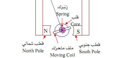
20 PMMC Construction The ain feature is a peranent agnet with two soft-iron pole shoes. A cylindrical soft-iron core is positioned between the core and the faces of the pole shoes. The lightweight oving coil pivoted to ove within these narrow air gaps. The air gaps are ade as narrow as possible in order to have the strongest possible level of agnetic flux crossing the gaps. The current in the coil of a PMMC instruent ust flow in one particular direction to cause the pointer to ove (positively) fro the zero position over the scale. Because the PMMC is polarized, it can be used directed to easure alternating current.


21 PMMC Construction D Arsonval or horseshoe agnet Core-agnet 21
 N D ( N.")
22 Torque Equation and Scale When a current flows through a one-turn coil situated in a agnetic field, a force F is exerted on each side of the coil F ( Bl ) N newtons where N is the nuberof turns Total force on each side of the coil of N turns: F 2 B l N newtons The force on each side acts at a radius r, producing a deflecting torque: T T D D 2 B l B l B l N r N (2r) N D ( N. )
23 T BlN 2r BlND BA N D A=l.D, Where D is the coil diaeter The controlling torque exerted by the spiral springs is directly proportional to the deforation or windup of the springs. Thus, the controlling torque is proportional to the actual angle of deflection of the pointer. T K where K C is a constant
24 For a given deflection, the controlling and deflecting torques are equal: K BlND BlND C where C K is a constant This equation shows that the pointer deflection is always proportional to the coil current. Consequently, the scale of the instruent is linear, or uniforly divided.
25 Exaple 1 v A PMMC instruent with a 100-turn coil has a agnetic flux density in its air gaps of B = 0.2 T. The coil diensions are D = 1 c and l = 1.5 c. Calculate the torque on the coil for a current of 1 A. Solution: T T D D B l N D 0.2 ( N. 2 ) (110 2 )


26 Galvanoeter t is a PMMC instruent designed to be sensitive to extreely low current levels. The siplest galvanoeter is a very sensitive instruent with the type of center-zero scale. Galvanoeters are often eployed to detect zero current or voltage in a circuit rather than to easure the actual level of current or voltage. The ost sensitive oving-coil galvanoeter use tautband suspension, and the controlling torque is generated by the twist in the suspension ribbon. For the for greatest sensitivity, the weight of the pointer can create a proble. The solution is by ounting a sall irror on the oving coil instead of a pointer Basic deflection syste of a galvanoeter using a light bea
27 An adjustable shunt resistor is eployed to protect the coil of a galvanoeter fro destructively excessive current levels. The shunt resistance is initially set to zero, then gradually increased to divert current through the galvanoeter. 27
28 Exaple 2 v A galvanoeter has a current sensitivity of 1 A/ and a critical daping resistance of 1 k. Calculate (a) the voltage sensitivity and (b) the egaoh sensitivity. Solution: oltage sensitivity 1kΩ1 A 1/ For a voltage sensitivity of 1/, 1/ egoh sensitivity 1MΩ 1 A
29 DC Aeter An aeter is always connected in series with a circuit in which current is to be easured. To avoid affecting the current level in the circuit, the aeter ust have a resistance uch lower than the circuit resistance. For larger currents, the instruent ust be odified so that ost of the current to be easured is shunted (a very low shunt resister) around the coil of the eter. Only a sall portion of oving coil. the current passes through the

30 A dc aeter consists of a PMMC instruent and a lowresistance shunt. sh sh sh sh sh sh sh
31 Exaple 3 A PMMC instruent has FSD of 100 A and a coil resistance of 1 k. Calculate the required shunt resistance value to convert the instruent into an aeter with (a) FSD = 100 A and (b) FSD = 1 A. Solution: (a) FSD = 100 A s s s s 100 (b) FSD = 1 A s s s μ A 1 kω 100 A μ Ω 99.9 A A A μ A A Ω A A
32 Exaple: An aeter has a PMMC instruent with a coil resistance of = 99 and FSD current of 0.1 A. Shunt resistance s = 1. Deterine the total current passing through the aeter at : a) FSD, b) 0.5 FSD, and c) 0.25 FSD Solution (a) At FSD eter voltage and 0.1A 99Ω 9.9 s s s A 1Ω s totalcurrent 9.9A 0.1A s 10A 32
33 (b) At 0.5 FSD (c) At 0.25 FSD A A A 0.05 A 0.05 A s A 1 s total current 4.95 A 0.5 A 5 A s A s A 1 s total current A A 2.5 A s Thus, the aeter scale ay be calibrated linearly fro zero to 10A
34 Aeter Swaping esistance The oving coil in a PMMC instruent is wound with thin copper wire, and its resistance can change significantly when its teperature changes. The heating effect of the coil current ay be enough to produce a resistance change, which will introduce an error. To iniize this error, a swaping resistance ade of anganin or constantan is connected in series with the coil: (anganin and constantan have resistance teperature coefficients very close to zero). The aeter shunt ust also be ade of anganin or constantan to avoid shunt resistance variations with teperature.
35 Multirange Aeters Make-before-break switch The instruent is not left without a shunt in parallel with it even for a brief instant. f this occurred, the high resistance of the instruent would affect the current flowing in the circuit. During switching there are actually two shunts in parallel with the instruent. 35

36 Ayrton Shunt The figure shows another ethod of protecting the deflection instruent of an aeter fro excessive current flow when switching between shunts. esistors 1, 2, and 3 constitute an Ayrton Shunts sh nternal Aeter esistance: in in / / s * in sh * * sh sh sh 36
37 Exaple: A PMMC instruent has a three-resistor Ayrton shunt connected across it to ake an aeter as shown in the figure. The resistance values are 1 = 0.05, 2 = 0.45 and 3 = 4.5. The eter has = 1k and FSD = 50A. Calculate the three ranges of the aeter. Solution Switch at contact B 50μA 1kΩ 50 s s s 50 10A 0.05Ω 0.45Ω 4.5Ω μA 10A s 10.05A 37
38 Switch at contact C s s 1 50 μa1kω 4.5 Ω s A s A 0.05 Ω0.45 Ω 50 μa100a 50 Switch at contact D s s s 1 50μ01kΩ 4.5Ω 0.45Ω 50 1A 0.05Ω A s μ0 1A 50
39 Accuracy and Aeter Loading Effects nternal resistance of ideal aeter is zero Oh, but in practice, the internal resistance has soe values which affect the easureent results. This error can be reduced by using higher range of easureent. Let us calculate the relationship between the true value and the easured value T Th ( true value ) Th ( easured value ) Th Th in dc circuit with source and resistors T th th T Accuracy T h T T h in % Acc 100% T T h T h in 100% dc circuit with source and resistors A th th A 39
40 Exaple: For a DC Circuit as shown in the figure, given 1 =2k, 2 =2k with voltage of 2. By easuring the current flow through 3 with a dc aeter with internal resistance of in = 100Ω, calculate percentage of accuracy and percentage of error. Solution Th / / 2 kω Th Th T E kω kω 2 kω Th 1 500μA 2kΩ Th Th μA 2 kω100ω Th in Th μa % Error 1 % A cc % 4.76% 500 μa % Acc 100% 95.24% T 40
41 DC olteter The deflection of a PMMC instruent is proportional to the current flowing through the oving coil. The coil current is directly proportional to the voltage across the coil. The coil resistance is norally quite sall, and thus the coil voltage is also usually very sall. Without any additional series (ultiplier resistance) resistance the PMMC instruent would only easure very low voltage. The volteter range is easily increased by connecting a resistance in series with the instruent. The eter current is directly proportional to the applied voltage, so that the eter scale can be calibrated to indicate the voltage.
 for certain voltage range (FSD).")

42 The volteter range is increased by connecting a ultiplier resistance with the instruent (single or individual type of extension of range). s s 1 s Last equation can be used to select the ultiplier resistance value ( s ) for certain voltage range (FSD). n this case will be the full scale current. A ultiplier resistance that is nine ties the coil resistance will increase the volteter range by a factor of 10 (ultiplier resistance + coil resistance) The volteter sensitivity (S) is defined as the total volteter resistance (internal resistance in ) divided by the voltage range (full scale)
43 Exaple: A PMMC instruent with FSD of 100 A and a coil resistance of 1k is to be converted into a volteter. Deterine the required ultiplier resistance if the volteter is to easure 50 at full scale and olteter sensitivity. Also calculate the applied voltage when the instruent indicate 0.8, 0.5, and 0.2 of FSD. Solution At 50 FSD s s μa s 1kΩ 499 kω 100 μa
44 Since the volteter has a total resistance of v = s + = 500k, then its resistance per volt or sensitivity is 500k / 50 =10 k /. At 0.8 of FSD μa 80 μa s 80 μa 499 kω1kω 40 At 0.5 of FSD At 0.2 of FSD 50μA 50μA 499 kω1kω 25 20μA 20μA 499 kω 1kΩ 10 Thus, the volteter scale ay be calibrated linearly fro zero to 50
45 olteter Swaping esistance As in the case of aeter, the change in coil resistance ( ) with teperature change can introduce errors in a PMMC volteter. The presence of the volteter ultiplier resistance ( s ) tends to swap coil resistance changes, except for low voltage ranges where s is not very uch larger than. n soe cases it ight be necessary to construct the ultiplier resistance for anganin or constantan. Multirange olteters ndividual or series connected resistors ay be used as shown in the following configurations Multirange volteter with ranges = ( +) where can be 1, 2, or 3 Multirange series volteter with ranges = ( +), where can be 1, 1 + 2, or
46 Exaple: A PMMC instruent with FSD = 50A and = 1700 is to be eployed as a volteter with ranges of 10, 50, and 100. Calculate the required values of ultiplier resistors for the two circuits shown in the previous slides. Solution For the circuit shown Switch contact at + 1 = = Ω 200 kω 1.7 kω 50 μa kω Switch contact at A k 1700Ω Switch contact at Ω 50 A M 46
47 For the circuit shown Switch contact at Ω kω 50 μa Switch contact at kω 1700 Ω 800 kω 50 μa Switch contact at kω kω 1700 Ω 1 M Ω 50 μa
48 Accuracy and olteter Loading Effect Let us calculate the relationship between the true value ( T ) and the easured value ( ) T T T Th Th in Th in Accuracy in T in Th % Acc 100% T in % Acc 100% in Th 48
49 Exaple: A volteter with sensitivity of 20kΩ/ is used for easuring a voltage across 2 with range of 50 as shown in the figure below. Calculate a) reading voltage. b) accuracy of easureent. c) error of easureent Solution E 100 Th T 2 200k k 200k / / 200 k / / 200 k 100 k Th k a) in S ange 50 1M in 1M T in Th 1M 100k b ) A ccuracy or % A cc 90.9% 50 T Th Th c ) Error 1 A cc or % Error 9.1%
50 AC olteter Full-Wave ectifier olteter Half-Wave ectifier olteter Half-Wave Full Bridge ectifier olteter
51 AC Aeter and olteter When an alternating current (sinusoidal ) with a very low frequency (0.1 Hz or lower) is passed through a PMMC instruent, the pointer tends to follow the instantaneous level of the AC. As the current grows positively, the pointer deflection increases to a axiu at the peak of the ac. Then as the instantaneous current level falls, the pointer deflection decreases towards zero. When the ac goes negative, the pointer is deflected (off-scale) to the left of zero. With the noral 50 Hz or higher supply frequencies, the daping echaniss and the inertia of the eter oveent prevent the pointer fro following the changing instantaneous levels of the signal. The instruents pointer settles at the average value of the current flowing through the oving coil which is zero. PMMC instruent can be odified by one of the following circuits to easure AC signals
52 1. Full-Wave Bridge ectifier olteter When the input is positive, diodes D 1 and D 4 conduct, causing current to flow through the eter fro top to botto ( red solid path). When the input goes negative, diodes D 2 and D 3 conduct, current flows through the eter fro the positive to the negative terinal ( blue dashed path). The ac volteter uses a series-connected ultiplier resistor ( s ) to liit the current flow through the p instruent. av The eter deflection is proportional to the average current ( av ), which is peak current ( p or ). But the actual current (or voltage) to be indicated in ac easureent is norally the rs = p (or ). ( note rs = 1.11 av p (or ) = rs ) When other than pure sine waves are applied, the volteter will not indicate the rs voltage. rs
53 s D 2 D 4 D 3 applied peak voltage( ) - rectifiers voltage drop rs 2 totat circuit resistance p rs F s F is rectifier voltage drops for D 1 and D 2 or D 3 and D 4 Peak current = av /0.637 = FSD /0.637 Exaple: A PMMC instruent with FSD = 100 µa and = 1 kω is to be eployed as an ac volteter with FSD = 200 (rs). Silicon diodes with F = 0.7 are used in the bridge rectifier circuit of shown above. Calculate: (a) the ultiplier resistance value required, (b) the pointer indications the rs input voltage is (i)100 and (ii) 50.
54 Solution At FSD, the average current flowing through the PMMC instruent is 100µA av 157 A p rs olt p 2 F (a) (b) s i-for the rs input voltage is 100 s p 2 F ( ) 1k k 3 (15710 ) A \ 2 \ p F A ( ) k s A 50 A 0.5FSD \ \ av ii- Siilarly, for the rs input voltage is 50 25A 0.25FSD \\ av
55 2. Half-Wave ectifier olteter SH shunting the eter is included to cause a relatively large current to flow through diode D 1 (larger than the eter current) when the diode is forward biased. This is ensure that the diode is biased beyond the knee and will into the linear range of its characteristics. Diode D 2 conducts during the negative half-cycles of the input. When conducting, D 2 cause a sall voltage drop across D 1 and the eter, thus preventing the flow of any significant reverse leakage current ( and reverse voltage) through the eter via D 1. n the half wave rectifier
56 Half-Bridge Full-Wave ectifier olteter During the positive half-cycle of the input, diode D 1 is forward biased and D 2 is reverse biased. Current flows fro terinal 1 through D 1 and the eter and then through 2 to terinal 2. but 1 is in parallel with the eter and 2. Therefore, uch of the current flowing in D 1 pass through 1 while only part of it flows through the eter and 2 During the negative half-cycle, diode D 2 is forward biased and D 1 is reverse biased. Current flows fro terinal 2 through 1 and the eter and then through D 2 to terinal 1. New, 2 is in parallel with the series connected eter and 1 This arrangeent forces the diodes to operate beyond the knee of their characteristics and helps to copensate for differences that ight occur in the characteristics of D 1 and D 2.
57 AC Aeter Like a dc aeter, an ac aeter ust have a very low resistance because it is always connected in series with the circuit in which current is to be easured. This low-resistance requireent eans that the voltage drop across the aeter ust be very sall, typically not greater than The voltage drop across a diode is 0.3 to 0.7. The use of a current transforer gives the aeter a low terinal resistance and low voltage drop.
 is connected across terinal A and B.")
58 A. Series Oheter Oheter Basic Circuit and Scale The siplest circuit consists of a voltage source (E b ) connected in series with a pair of terinals (A & B), a standard resistance ( 1 ), and a low-current PMMC instruent. The resistance to be easured ( x ) is connected across terinal A and B. The eter current E ( + + ) b x 1 When the oheter terinals are shorted ( x = 0) eter full-scale deflection occurs. FSD = E b / ( 1 + ) At half-scale deflection x = 1 + At zero deflection the terinals are open-circuited ( x = ).
59 Exaple : The series oheter shown in Figure is ade up of a 1.5 battery, a 100 µa eter, and a resistance 1 which akes ( 1 + ) =15kΩ. a) Deterine the instruent indication when x = 0. b) Deterine how the resistance scale should be arked at 0.75 FSD, 0.5 FSD and 0.25 FSD Solution E b 1.5 a) 100 A FS D 0 15k x 1 b ) A t 0.75 FSD : 3100A E b 75 A & x 1 4 Eb x k 5k 75A 100A 1.5 At 0.5 FSD : 50 A & x 15k 15k 2 50A
60 100A 1.5 At 0.25 FSD : 25 A & x 15k 45k 4 25A The oheter scale is now arked as shown in the figure. t is clear that the oheter scale is nonlinear. Coents: disadvantages of siple series oheter The siple oheter described in last exaple will operate satisfactorily as long as the battery voltage reains exactly at 1.5. When the battery voltage falls, the instruent scale is no longer correct. Although ๑ were adjusted to give FSD when terinals A and B are shortcircuited, the scale would still be in error because now id-scale would represent a resistance equal to the new value of 1 +.
61 Oheter with Zero Adjust Falling battery voltage can be taken care by an adjustable resistor ( 2 ) connected in parallel with the eter. With terinals A and B short-circuited, the total circuit resistance is 1 + ( 2 // ). Since 1 is always very uch larger than 2 //, the total circuit resistance can be assued to equal 1 E b b = E b x \\ if 2 \\ << 1 then b + A lso, the eter voltage is = \\ which give eter current as = x 1 b 2 When x equal to 1 the circuit resistance is doubled and the circuit current is halved. This cause both 2 and to be reduced to half of their previous level. Thus the id-scale easured resistance is again equal to 1. \\ b 2 Each tie the oheter is used, terinals A and B are first short circuited, and 2 is adjusted for zero-oh indication on the scale
 would have to be ade every tie the resistance range ( 1 ) is")
62 The series oheter can be converted to a ulti-range oheter by eploying several values of standard resistance 1 and a rotatory switch The ajor inconvenience of such a circuit is that a large adjustent of the zero control ( 2 ) would have to be ade every tie the resistance range ( 1 ) is changed.
63 Exaple: An oheter as shown in the figure with E b = 1.5, 1 = 15kΩ, = 2 = 50Ω and FSD = 50µA. Calculate, (a) x at 0.5FSD, (b) when E b = 1.3 what is the value of 2 to get full-scale current and (c) when E b = 1.3 what is the value of x at halfscale current. Solution Since ( // 2 ) = 25 << 1 then at half scale x = 1 = 15k independent of E b (a) 25 A A 25 A 25 A 50 A b E 1.5 x 1 30k 50 A b E x 1 30k 15k 15k b
64 (b) (c) b 2 2 Eb A 0 15k x A 50A 36.67A b FSD 50A FSD A 2 5 A A A 2 5 A A b E 1.3 x k A 3 0 k 3 0 k 1 5 k x x 1 5 k b 1 Since ( // 2 ) = << 1 then at half scale x = 1 = 15k independent of E b
65 B. Shunt Oheter Basic Circuit and Scale The siplest circuit consists of a voltage source (E) connected with an adjusted esistor ( Adj ) and a low-current PMMC instruent. The resistance to be easured ( x ) is connected across terinal A and B. When x = 0, short circuit between A and B, there will be no current flow in the coil branch and the scale point at zero on the left hand side. When x =, open circuit between A and B. Then adjust Adj to get FSD. The eter will point infinity at the right of the scale. E FS D A dj For any x we have, E x Adj x Adj Scale of shunt oheter is opposite to the scale of series oheter when connecting with x

66 THANK YOU FO YOU ATTENTON!!
Part 9: Basic AC Theory
 Part 9: Basic AC Theory 9.1 Advantages Of AC Systes Dealing with alternating current (AC) supplies is on the whole ore coplicated than dealing with DC current, However there are certain advantages of AC
Sine waves by far the most important form of alternating quantity important properties are shown below
 AC DC METERS 1 Sine waves by far the most important form of alternating quantity important properties are shown below 2 Average value of a sine wave average value over one (or more) cycles is clearly zero
Unit-02 Basic Electricity I
 Unit-0 Basic Electricity Objective: n this experient, we would like to get you ailiar with the theore, structure and use o ultieter and learn the easureent o Alternating Current (AC) / Direct Current (DC)
UNIT - II CONTROLLED RECTIFIERS (Line Commutated AC to DC converters) Line Commutated Converter
 Line Commutated Converter") UNIT - II CONTROLLED RECTIFIERS (Line Coutated AC to DC converters) INTRODUCTION TO CONTROLLED RECTIFIERS Controlled rectifiers are line coutated ac to power converters which are used to convert a fixed
UNIT - II CONTROLLED RECTIFIERS (Line Coutated AC to DC converters) INTRODUCTION TO CONTROLLED RECTIFIERS Controlled rectifiers are line coutated ac to power converters which are used to convert a fixed
ELECTRICAL ENGINEERING [UKSSSC (JE) ELECTRICAL/ELECTRONICS]
![ELECTRICAL ENGINEERING [UKSSSC (JE) ELECTRICAL/ELECTRONICS]](/thumbs/90/103893232.jpg "ELECTRICAL ENGINEERING [UKSSSC (JE) ELECTRICAL/ELECTRONICS]") Class Centre-Pithuwala Karanpur; HO: Shila bypass road near Governent polytechnic Pithuwala Dehradun Mob:084495973,0943406 Web: www.engineeringacadey.co.in E-ail:engineeringacadeyddn@gail.co. How uch energy
Class Centre-Pithuwala Karanpur; HO: Shila bypass road near Governent polytechnic Pithuwala Dehradun Mob:084495973,0943406 Web: www.engineeringacadey.co.in E-ail:engineeringacadeyddn@gail.co. How uch energy
A.C. FUNDA- MENTALS. Learning Objectives
 C H A P T E R Learning Objectives Generation of Alternating Voltages and Currents Alternate Method for the Equations of Alternating Voltages and currents Siple Wavefors Cycle Different Fors of E.M.F. Equation
AC Fundamental. Simple Loop Generator: Whenever a conductor moves in a magnetic field, an emf is induced in it.
 A Fundaental Siple oop Generator: Whenever a conductor oves in a agnetic field, an ef is induced in it. Fig.: Siple oop Generator The aount of EMF induced into a coil cutting the agnetic lines of force
Question & its Answer
 Iportant Instructions to exainers: 1) The answers should be exained by keywords and not as word-to-word as given in the odel answer schee. 2) The odel answer and the answer written by candidate ay vary
Secondary-side-only Simultaneous Power and Efficiency Control in Dynamic Wireless Power Transfer System
 069060 Secondary-side-only Siultaneous Power and Efficiency Control in Dynaic Wireless Power Transfer Syste 6 Giorgio ovison ) Daita Kobayashi ) Takehiro Iura ) Yoichi Hori ) ) The University of Tokyo,
ALTERNATING CURRENT (A.C. CIRCUITS)
") AENANG UEN (SHO) 3-4 PAGE: AENANG UEN (A.. US) Alternating current An electrical current, agnitude of which changes with tie and polarity reverses periodically is called alternating current (A.) he sinusoidal
AENANG UEN (SHO) 3-4 PAGE: AENANG UEN (A.. US) Alternating current An electrical current, agnitude of which changes with tie and polarity reverses periodically is called alternating current (A.) he sinusoidal
Chapter 6. POWER AMPLIFIERS
 hapter 6. OWER AMFERS An aplifying syste usually has several cascaded stages. The input and interediate stages are sall signal aplifiers. Their function is only to aplify the input signal to a suitable
Analog Multimeter. household devices.
 1 Analog Multimeter A multimeter or a multitester, a.k.a.vom (volt-ohmmilliammeter), is an electronic measuring instrument that combines several measurement functions in one unit. A typical multimeter
Einstein Classes, Unit No. 102, 103, Vardhman Ring Road Plaza, Vikas Puri Extn., Outer Ring Road New Delhi , Ph. : ,
 AENAING CUEN PAC 7. Introduction : Q. What is direct current? Solution : Direct current does not change direction with tie. Q. What is alternating current? Solution : Alternating currents and voltages
The sensor must not be placed behind a panel or any other material.
 EAGLE THREE - N USER S GUIDE SELFMONITORED MOTION SENSOR FOR AUTOMATIC ESCAPE DOORS* TECHNICAL SPECIFICATION Technology : icrowave and icroprocessor Transitter frequency : 24.150 GHz Transitter radiated
Compensated Single-Phase Rectifier
 Copensated Single-Phase Rectifier Jānis DoniĦš Riga Technical university jdonins@gail.co Abstract- Paper describes ethods of rectified DC pulsation reduction adding a ensation node to a single phase rectifier.
SAMPLE OF THE STUDY MATERIAL PART OF CHAPTER 2 Measurements of Basic Electrical Quantities 1 (Current Voltage, Resistance)
") SAMPLE OF THE STUDY MATERIAL PART OF CHAPTER 2 Measurements of Basic Electrical Quantities 1 (Current Voltage, Resistance) 2.1 Indicating Instruments Analog Instruments: An analog device is one in which
SAMPLE OF THE STUDY MATERIAL PART OF CHAPTER 2 Measurements of Basic Electrical Quantities 1 (Current Voltage, Resistance) 2.1 Indicating Instruments Analog Instruments: An analog device is one in which
Experiment 7: Frequency Modulation and Phase Locked Loops October 11, 2006
 Experient 7: Frequency Modulation and Phase ocked oops October 11, 2006 Frequency Modulation Norally, we consider a voltage wave for with a fixed frequency of the for v(t) = V sin(ω c t + θ), (1) where
On the field of view of a Galilean telescope
 Transactions of the Optical Society On the field of view of a Galilean telescope To cite this article: H A Hughes and P F Everitt 1920 Trans. Opt. Soc. 22 15 View the article online for updates and enhanceents.
WIPL-D Pro: What is New in v12.0?
 WIPL-D Pro: What is New in v12.0? Iproveents/new features introduced in v12.0 are: 1. Extended - Extree Liits a. Extreely LOW contrast aterials b. Extended resolution for radiation pattern c. Extreely
Chapter 10 Threaded Fasteners and Power Screws
 Chapter 10 Threaded Fasteners and Power Screws 10.1 Introduction A layan ight consider threaded fasteners (screws, nuts, and bolts) to be the ost undane and uninteresting of all achine eleents. In fact
Half-wave Rectifier AC Meters
 Note-4 1 Half-wave Rectifier AC Meters Disadvantages: 1. In negative half-cycle, reverse current flows through the circuit reduces average value of current meter reads lower than actual. 2. High peak inverse
OTC Statistics of High- and Low-Frequency Motions of a Moored Tanker. sensitive to lateral loading such as the SAL5 and
 OTC 61 78 Statistics of High- and Low-Frequency Motions of a Moored Tanker by J.A..Pinkster, Maritie Research Inst. Netherlands Copyright 1989, Offshore Technology Conference This paper was presented at
MEASUREMENTS & INSTRUMENTATION ANALOG AND DIGITAL METERS
 MEASUREMENTS & INSTRUMENTATION ANALOG AND DIGITAL METERS ANALOG Metering devices Provides monotonous (continuous) movement. ELECTRICAL MEASURING INSTRUMENTS ANALOG METERS A d Arsonval galvanometer (Moving
Power Electronics Lecture No. 7 Dr. Mohammed Tawfeeq. (a) Circuit (b) Waveform Fig.7.1
 Circuit (b) Waveform Fig.7.1") 7. Single-phase Half Controlled ( Seiconverter) Rectifier Fig. 7.1 (a) shows a single-phase half-controlled (seiconverter) rectifier. This configuration consists of a cobination of thyristors and diodes
7. Single-phase Half Controlled ( Seiconverter) Rectifier Fig. 7.1 (a) shows a single-phase half-controlled (seiconverter) rectifier. This configuration consists of a cobination of thyristors and diodes
Acoustic Doppler Current Profiler (ADCP): Principles of Operation and Setup
: Principles of Operation and Setup") SMARTSkills Workshop for Vessel Users and Researchers, Marine Institute, Galway 29th April 2016 Acoustic Doppler Current Profiler (ADCP): Principles of Operation and Setup Christian Mohn & Martin White
SMARTSkills Workshop for Vessel Users and Researchers, Marine Institute, Galway 29th April 2016 Acoustic Doppler Current Profiler (ADCP): Principles of Operation and Setup Christian Mohn & Martin White
Relation between C/N Ratio and S/N Ratio
 Relation between C/N Ratio and S/N Ratio In our discussion in the past few lectures, we have coputed the C/N ratio of the received signals at different points of the satellite transission syste. The C/N
ELEC2202 Communications Engineering Laboratory Frequency Modulation (FM)
") ELEC Counications Engineering Laboratory ---- Frequency Modulation (FM) 1. Objectives On copletion of this laboratory you will be failiar with: Frequency odulators (FM), Modulation index, Bandwidth, FM
ELEC Counications Engineering Laboratory ---- Frequency Modulation (FM) 1. Objectives On copletion of this laboratory you will be failiar with: Frequency odulators (FM), Modulation index, Bandwidth, FM
ANALOGUE & DIGITAL COMMUNICATION
 1 ANALOGUE & DIGITAL COMMUNICATION Syed M. Zafi S. Shah & Uair Mujtaba Qureshi Lectures 5-6: Aplitude Modulation Part 1 Todays topics Recap of Advantages of Modulation Analog Modulation Defining Generation
AccuBridge TOWARDS THE DEVELOPMENT OF A DC CURRENT COMPARATOR RATIO STANDARD
 AccuBridge TOWARD THE DEVELOPMENT OF A DC CURRENT COMPARATOR RATO TANDARD Duane Brown,Andrew Wachowicz, Dr. hiping Huang 3 Measureents nternational, Prescott Canada duanebrown@intl.co, Measureents nternational,
Torsion System. Encoder #3 ( 3 ) Third encoder/disk for Model 205a only. Figure 1: ECP Torsion Experiment
 Third encoder/disk for Model 205a only. Figure 1: ECP Torsion Experiment") Torsion Syste Introduction This lab experient studies dynaics of a torsional syste with single and ultiple degrees of freedo. The effects of various control configurations are studied in later part of
Torsion Syste Introduction This lab experient studies dynaics of a torsional syste with single and ultiple degrees of freedo. The effects of various control configurations are studied in later part of
Unit 9. Alternating current
 nit 9 Alternating current 9. ntroduction 9. Features of an A.C. 9.3 Behaviour of basic dipoles facing an A.C. 9.4 RLC series circuit. pedance and phase lag. 9.5 Power on A.C. 9.6 Questions and probles
Mutual Inductance. L (1) l
 l") Mutual Inductance Developers Objectives Preparation Background JD Mitchell, AB Overby and K Meehan The objectives of this experient are to design and construct a transforer and deterine its losses as well
Mutual Inductance Developers Objectives Preparation Background JD Mitchell, AB Overby and K Meehan The objectives of this experient are to design and construct a transforer and deterine its losses as well
HIGH FREQUENCY LASER BASED ACOUSTIC MICROSCOPY USING A CW GENERATION SOURCE
 HIGH FREQUENCY LASER BASED ACOUSTIC MICROSCOPY USING A CW GENERATION SOURCE T.W. Murray, O. Balogun, and N. Pratt Departent of Aerospace and Mechanical Engineering, Boston University, Boston MA 0225 Abstract:
UNIT II MEASUREMENT OF POWER & ENERGY
 UNIT II MEASUREMENT OF POWER & ENERGY Dynamometer type wattmeter works on a very simple principle which is stated as "when any current carrying conductor is placed inside a magnetic field, it experiences
EXPERIMENTATION FOR ACTIVE VIBRATION CONTROL
 CHPTER - 6 EXPERIMENTTION FOR CTIVE VIBRTION CONTROL 6. INTRODUCTION The iportant issues in vibration control applications are odeling the sart structure with in-built sensing and actuation capabilities
Eddy-Current-Based Contactless Speed Sensing of Conductive Surfaces
 1 IEEE Proceedings of the Southern Power Electronics Conference (SPEC 1), Auckland, New Zealand, Deceber 5-, 1 Eddy-Current-Based Contactless Speed Sensing of Conductive Surfaces A. Tüysüz, M. Flankl,
Modeling and Parameter Identification of a DC Motor Using Constraint Optimization Technique
 IOSR Journal of Mechanical and Civil Engineering (IOSR-JMCE) e-issn: 2278-684,p-ISSN: 2320-334X, Volue 3, Issue 6 Ver. II (Nov. - Dec. 206), PP 46-56 www.iosrjournals.org Modeling and Paraeter Identification
XII PHYSICS INSTRUMENTS] CHAPTER NO. 15 [ELECTRICAL MEASURING MUHAMMAD AFFAN KHAN LECTURER PHYSICS, AKHSS, K
![XII PHYSICS INSTRUMENTS] CHAPTER NO. 15 [ELECTRICAL MEASURING MUHAMMAD AFFAN KHAN LECTURER PHYSICS, AKHSS, K](/thumbs/80/81415743.jpg "XII PHYSICS INSTRUMENTS] CHAPTER NO. 15 [ELECTRICAL MEASURING MUHAMMAD AFFAN KHAN LECTURER PHYSICS, AKHSS, K") XII PHYSICS MUHAMMAD AFFAN KHAN LECTURER PHYSICS, AKHSS, K affan_414@live.com https://promotephysics.wordpress.com [ELECTRICAL MEASURING INSTRUMENTS] CHAPTER NO. 15 MOVING COIL GALVANOMETER An electrical
XII PHYSICS MUHAMMAD AFFAN KHAN LECTURER PHYSICS, AKHSS, K affan_414@live.com https://promotephysics.wordpress.com [ELECTRICAL MEASURING INSTRUMENTS] CHAPTER NO. 15 MOVING COIL GALVANOMETER An electrical
ELECTRICAL MEASUREMENTS
 R10 Set No: 1 1. a) Derive the expression for torque equation for a moving iron attraction type instrument and comment up on the nature of scale [8] b) Define the terms current sensitivity, voltage sensitivity
Camera 2 Lens 4 Filters 7 Film Image Sensor 9 Flash Units 12 Film v. Digital 17 Equipment Selection Guidelines 21 SAMPLE. Resource List.
 Basic Evidence Photography Contents Table of Contents Equipent Considerations. 2 Caera 2 Lens 4 Filters 7 Fil Iage Sensor 9 Flash Units 12 Fil v. Digital 17 Equipent Selection Guidelines 21 Scene Photography
POWER QUALITY ASSESSMENT USING TWO STAGE NONLINEAR ESTIMATION NUMERICAL ALGORITHM
 POWER QUALITY ASSESSENT USING TWO STAGE NONLINEAR ESTIATION NUERICAL ALGORITH Vladiir Terzia ABB Gerany vadiir.terzia@de.abb.co Vladiir Stanoevic EPS Yugoslavia vla_sta@hotail.co artin axiini ABB Gerany
LOW COST PRODUCTION PHASE NOISE MEASUREMENTS ON MICROWAVE AND MILLIMETRE WAVE FREQUENCY SOURCES
 Page 1 of 10 LOW COST PRODUCTION PHASE NOISE MEASUREMENTS ON MICROWAVE AND MILLIMETRE WAVE FREQUENCY SOURCES Hugh McPherson Spectral Line Systes Ltd, Units 1,2&3 Scott Road, Tarbert, Isle of Harris. www.spectral-line-systes.co.uk
Design of a Microcontroller Based Automatic Voltage Stabilizer with Toroidal Transformer
 Design of a Microcontroller Based utoatic Voltage Stabilizer with Toroidal Transforer Thet Htun ung Departent of Electrical Power Engineering Mandalay Technological University Myanar bstract- Every electrical
Additive Synthesis, Amplitude Modulation and Frequency Modulation
 Additive Synthesis, Aplitude Modulation and Frequency Modulation Pro Eduardo R Miranda Varèse-Gastproessor eduardo.iranda@btinternet.co Electronic Music Studio TU Berlin Institute o Counications Research
Amplifiers and Feedback
 6 A Textbook of Operational Transconductance Aplifier and AIC Chapter Aplifiers and Feedback. INTRODUCTION Practically all circuits using Operational Transconductance Aplifiers are based around one of
Lesson 1: Introduction to Control Systems Technology
 8/7/05 Lesson : Introduction to ontrol Systes Technology ET 48a Autoatic ontrol Systes Technology lessonet48a.pptx Learning Objectives After this presentation you will be able to: Explain the function
SIG: Signal-Processing
 TH Köln - Technology, Arts, Sciences Prof. Dr. Rainer Bartz SIG: Signal-Processing Copendiu (6) Prof. Dr.-Ing. Rainer Bartz rainer.bartz@th-koeln.de Contact: eail: website: office: rainer.bartz@th-koeln.de
Green Laser 8 times better visibility
 P Mk2 Docuenting Portable Infrared Theroeters Cutting Edge Technology for Maintenance Technicians INFRARED Teperature Range up to 3 C Green Laser 8 ties better visibility Rugged with Protective Rubber
Electrical Engineering / Electromagnetics
 Electrical Engineering / Electromagnetics. Plot voltage versus time and current versus time for the circuit with the following substitutions: A. esistor B. Capacitor C. Inductor t = 0 A/B/C A. I t t B.
EE Chapter 7 Measuring Instruments
 EE 2145230 Chapter 7 Measuring Instruments 7.1 Meter Movements The basic principle of many electric instruments is that of the galvanometer. This is a device which reacts to minute electromagnetic influences
Chapter 4. Junction Field Effect Transistor Theory and Applications
 Chapter 4 Junction Field Effect Transistor Theory and Applications 4.0 ntroduction Like bipolar junction transistor, junction field effect transistor JFET is also a three-terinal device but it is a unipolar
Robust Acceleration Control of Electrodynamic Shaker Using µ Synthesis
 Proceedings of the 44th IEEE Conference on Decision and Control, and the European Control Conference 5 Seville, Spain, Deceber -5, 5 WeIC8. Robust Acceleration Control of Electrodynaic Shaker Using µ Synthesis
EXPERIMENTAL VERIFICATION OF SINUSOIDAL APPROXIMATION IN ANALYSIS OF THREE-PHASE TWELVE-PULSE OUTPUT VOLTAGE TYPE RECTIFIERS
 th INTERNATIONAL SYPOSIU on POWER ELECTRONICS - Ee 9 XV eđunarodni sipoziju Energetska elektronika Ee 9 NOVI SAD, REPUBLIC OF SERBIA, October 8 th - th, 9 EXPERIENTAL VERIFICATION OF SINUSOIDAL APPROXIATION
Research Article Novel Design for Reduction of Transformer Size in Dynamic Voltage Restorer
 Research Journal of Applied Sciences, Engineering and Technology 8(19): 057-063, 014 DOI:10.1906/rjaset.8.1198 ISSN: 040-7459; e-issn: 040-7467 014 Maxwell Scientific Publication Corp. Subitted: April
] (1) Problem 1. University of California, Berkeley Fall 2010 EE142, Problem Set #9 Solutions Prof. Jan Rabaey
![] (1) Problem 1. University of California, Berkeley Fall 2010 EE142, Problem Set #9 Solutions Prof. Jan Rabaey](/thumbs/81/84143587.jpg "] (1) Problem 1. University of California, Berkeley Fall 2010 EE142, Problem Set #9 Solutions Prof. Jan Rabaey") University of California, Berkeley Fall 00 EE4, Proble Set #9 Solutions Ain Arbabian Prof. Jan Rabaey Proble Since the ixer is a down-conversion type with low side injection f LO 700 MHz and f RF f IF
University of California, Berkeley Fall 00 EE4, Proble Set #9 Solutions Ain Arbabian Prof. Jan Rabaey Proble Since the ixer is a down-conversion type with low side injection f LO 700 MHz and f RF f IF
Department of Mechanical and Aerospace Engineering, Case Western Reserve University, Cleveland, OH, 2
 Subission International Conference on Acoustics, Speech, and Signal Processing (ICASSP ) PARAMETRIC AND NON-PARAMETRIC SIGNAL ANALYSIS FOR MAPPING AIR FLOW IN THE EAR-CANALTO TONGUE MOVEMENT: A NEW STRATEGY
Real Time Etch-depth Measurement Using Surface Acoustic Wave Sensor
 Australian Journal of Basic and Applied Sciences, (8): -7, 1 ISSN 1991-8178 Real Tie Etch-depth Measureent Using Surface Acoustic Wave Sensor 1 Reza Hosseini, Navid Rahany, 3 Behrad Soltanbeigi, Rouzbeh
Exercise MM About the Multimeter
 Exercise MM About the Multimeter Introduction Our world is filled with devices that contain electrical circuits in which various voltage sources cause currents to flow. Electrical currents generate heat,
ACCURATE DISPLACEMENT MEASUREMENT BASED ON THE FREQUENCY VARIATION MONITORING OF ULTRASONIC SIGNALS
 XVII IMEKO World Congress Metrology in 3rd Millenniu June 22 27, 2003, Dubrovnik, Croatia ACCURATE DISPLACEMENT MEASUREMENT BASED ON THE FREQUENCY VARIATION MONITORING OF ULTRASONIC SIGNALS Ch. Papageorgiou
MODERN ACADEMY FOR ENGINEERING & TECHNOLOGY IN MAADI
 MODERN ACADEMY FOR ENGINEERING & TECHNOLOGY IN MAADI 1 2/25/2018 ELECTRONIC MEASUREMENTS ELC_314 2 2/25/2018 Text Books David A. Bell, A. Foster Chin, Electronic Instrumentation & Measurements, 2 nd Ed.,
A Decoupling Structure of Controllable Reactor of Transformer Type
 TELKOMNIKA Indonesian Journal of Electrical Engineering Vol., No., January 5, pp. ~ 5 DOI:.59/telkonika.vi.67 A Decoupling Structure of Controllable Reactor of Transforer Type Yu He*, Huatai Chen Power
Design and Development Considerations of Voltage Controlled Crystal Oscillator (VCXO) Networks
 Networks") Design and Developent Considerations of Voltage Controlled Crystal Oscillator (VCXO) Networks David Green & Tony Scalpi, Cypress Seiconductor Corporation 2003 1.0 Overview The concept of placing piezoelectric
Design and Developent Considerations of Voltage Controlled Crystal Oscillator (VCXO) Networks David Green & Tony Scalpi, Cypress Seiconductor Corporation 2003 1.0 Overview The concept of placing piezoelectric
Determination of Typical Operating Conditions for
 1 1 ( A PUB.LICATION,OF THE RCA TUBE DIVISION Vol. 1, No. 3 Deceber, 195 Deterination of Typical Operating Conditions for RCA Tubes Used as Linear If Power Aplifiers During the past several years, there
PREDICTING SOUND LEVELS BEHIND BUILDINGS - HOW MANY REFLECTIONS SHOULD I USE? Apex Acoustics Ltd, Gateshead, UK
 PREDICTING SOUND LEVELS BEHIND BUILDINGS - HOW MANY REFLECTIONS SHOULD I USE? W Wei A Cooke J Havie-Clark Apex Acoustics Ltd, Gateshead, UK Apex Acoustics Ltd, Gateshead, UK Apex Acoustics Ltd, Gateshead,
CHAPTER 2 POSITION SERVO DRIVE OF BLDC MOTOR FOR SINGLE LINK ROBOTIC ARM
 22 CHAPTER 2 POSITION SERVO DRIVE OF BLDC MOTOR FOR SINGLE LINK ROBOTIC ARM 2.1 INTRODUCTION An industrial autoation involves robotic to handle aterials in different environents with different pay loads
INSTITUTE OF AERONAUTICAL ENGINEERING (Autonomous) Dundigal, Hyderabad
 Dundigal, Hyderabad") I INSTITUTE OF AERONAUTICAL ENGINEERING (Autonomous) Dundigal, Hyderabad-500043 CIVIL ENGINEERING TUTORIAL QUESTION BANK Course Name : BASIC ELECTRICAL AND ELECTRONICS ENGINEERING Course Code : AEE018
I INSTITUTE OF AERONAUTICAL ENGINEERING (Autonomous) Dundigal, Hyderabad-500043 CIVIL ENGINEERING TUTORIAL QUESTION BANK Course Name : BASIC ELECTRICAL AND ELECTRONICS ENGINEERING Course Code : AEE018
Characteristics of a Stand-Alone Induction Generator in Small Hydroelectric Plants
 Characteristics of a Stand-Alone nduction Generator in Sall Hydroelectric Plants M. H. Haque School of Electrical and Electronic Engineering Nanyang Technological University Singapore 69798 Abstract-This
Three Component Time-domain Electromagnetic Surveying: Modeling and Data Analysis
 PIERS ONLINE, VOL., NO., 75 Three Coponent Tie-doain Electroagnetic Surveying: Modeling and Data Analysis Chow-Son Chen 1, Wei-Hsuan Chiu 1, and Ching-Ren Lin 1 Institute of Geophysics, National Central
Diode Applications Half-Wave Rectifying
 Lab 5 Diode Applications Half-Wave ectifying Objectives: Study the half-wave rectifying and smoothing with a capacitor for a simple diode circuit. Study the use of a Zener diode in a circuit with an AC
presented on yfra.,- /4/,'d)
") AN ABSTRACT OF THE THESIS OF in Jaes Willia Walker for the MSEE (Nae) (Degree) Electrical Engineering presented on yfra.,- /4/,'d) (Date) Title: A PROGRAMMED INTRODUCTION TO MODULATION TECHNIQUES Abstract
AN ABSTRACT OF THE THESIS OF in Jaes Willia Walker for the MSEE (Nae) (Degree) Electrical Engineering presented on yfra.,- /4/,'d) (Date) Title: A PROGRAMMED INTRODUCTION TO MODULATION TECHNIQUES Abstract
Exploring the Electron Tunneling Behavior of Scanning Tunneling Microscope (STM) tip and n-type Semiconductor
 tip and n-type Semiconductor") Page 110 Exploring the of Scanning Tunneling Microscope (STM) tip and n-type Seiconductor M. A. Rahan * and J. U. Ahed Departent of Applied Physics, Electronics & Counication Engineering, University of
Page 110 Exploring the of Scanning Tunneling Microscope (STM) tip and n-type Seiconductor M. A. Rahan * and J. U. Ahed Departent of Applied Physics, Electronics & Counication Engineering, University of
Notes on Orthogonal Frequency Division Multiplexing (OFDM)
") Notes on Orthogonal Frequency Division Multiplexing (OFDM). Discrete Fourier ransfor As a reinder, the analytic fors of Fourier and inverse Fourier transfors are X f x t t, f dt x t exp j2 ft dt (.) where
Notes on Orthogonal Frequency Division Multiplexing (OFDM). Discrete Fourier ransfor As a reinder, the analytic fors of Fourier and inverse Fourier transfors are X f x t t, f dt x t exp j2 ft dt (.) where
INSTITUTE OF AERONAUTICAL ENGINEERING (AUTONOMOUS)
") Name Code Class Branch INSTITUTE OF AERONAUTICAL ENGINEERING (AUTONOMOUS) Dundigal, Hyderabad -500 043 CIVIL ENGINEERING TUTORIAL QUESTION BANK : ELECTRICAL AND ELECTRONICS ENGINEERING : A30203 : II B.
Name Code Class Branch INSTITUTE OF AERONAUTICAL ENGINEERING (AUTONOMOUS) Dundigal, Hyderabad -500 043 CIVIL ENGINEERING TUTORIAL QUESTION BANK : ELECTRICAL AND ELECTRONICS ENGINEERING : A30203 : II B.
Precise Indoor Localization System For a Mobile Robot Using Auto Calibration Algorithm
 Precise Indoor Localization Syste For a Mobile Robot Using Auto Calibration Algorith Sung-Bu Ki, JangMyung Lee, and I.O. Lee : Pusan National University, http://robotics.ee.pusan.ac.r, : Ninety syste Abstract:
DIGITAL Communications
 DIGITAL Counications Contents Introduction to Counication Systes Analogue Modulation AM, DSBSC, SB, SSB, FM, PM, Narrow band FM, PLL Deodulators, and FLL Loops Sapling Systes Tie and Frequency Division
Practical 2.1 BASIC ELECTRICAL MEASUREMENTS AND DATA PROCESSING
 Practical 2.1 BASIC ELECTRICAL MEASUREMENTS AND DATA PROCESSING September 6, 2017 1 Introduction To measure electrical quantities one uses electrical measuring instruments. There are three main quantities
INTERNATIONAL TELECOMMUNICATION UNION
 INTERNATIONAL TELECOMMUNICATION UNION ITU-T J.133 TELECOMMUNICATION STANDARDIZATION SECTOR OF ITU (07/2002) SERIES J: CABLE NETWORKS AND TRANSMISSION OF TELEVISION, SOUND PROGRAMME AND OTHER MULTIMEDIA
Session Eleven: An On-Line Technique to Detect Winding Deformation within Power Transformers
 Session Eleven: An On-Line Technique to Detect Winding Deforation within Power Transforers A. Abu-Siada Senior Lecturer, Curtin University Abstract Frequency Response Analysis (FRA) has been growing in
Parameter Identification of Transfer Functions Using MATLAB
 Paraeter Identification of Transfer Functions Using MATLAB Mato Fruk, Goran Vujisić, Toislav Špoljarić Departent of Electrical Engineering The Polytechnic of Zagreb Konavoska, Zagreb, Croatia ato.fruk@tvz.hr,
INSTITUTE OF AERONAUTICAL ENGINEERING Dundigal, Hyderabad
 Course Name Course Code Class Branch INSTITUTE OF AERONAUTICAL ENGINEERING Dundigal, Hyderabad -500 043 AERONAUTICAL ENGINEERING TUTORIAL QUESTION BANK : ELECTRICAL AND ELECTRONICS ENGINEERING : A40203
A HIGH POWER FACTOR THREE-PHASE RECTIFIER BASED ON ADAPTIVE CURRENT INJECTION APPLYING BUCK CONVERTER
 9th International onference on Power Electronics Motion ontrol - EPE-PEM Košice A HIGH POWER FATOR THREE-PHASE RETIFIER BASE ON AAPTIVE URRENT INJETION APPYING BUK ONVERTER Žarko Ja, Predrag Pejović EE
RADIO AMATEUR EXAM GENERAL CLASS
 RAE-Lessons by 4S7VJ 1 CHAPTER-7 RADIO AMATEUR EXAM GENERAL CLASS MEASURMENTS By 4S7VJ 7.1 TEST EQUIPMENT & MEASUREMENTS Correct operation of amateur radio equipment involves measurements to ensure optimum
CH 24 SLOPE. rise = run. Ch 24 Slope. Introduction
 9 CH SLOPE Introduction A line has any attributes, or characteristics. Two of the ost iportant are its intercepts and its slope. The intercepts (previous chapter) tell us where the line crosses the x-axis
UNIT II MEASUREMENT OF POWER AND ENERGY PART-A
 UNIT II MEASUREMENT OF POWER AND ENERGY PART-A 1. A 3 500 V motor load has a pf of 0.4. Two wattmeters connected to measure the input. They show the input to be 30 kw. Find the reading of each instrument
A 1.2V rail-to-rail 100MHz amplifier.
 University of Michigan, EECS413 Final project. A 1.2V rail-to-rail 100MHz aplifier. 1 A 1.2V rail-to-rail 100MHz aplifier. Mark Ferriss, Junghwan Han, Joshua Jaeyoung Kang, University of Michigan. Abstract
Adaptive Harmonic IIR Notch Filter with Varying Notch Bandwidth and Convergence Factor
 Journal of Counication and Coputer (4 484-49 doi:.765/548-779/4.6. D DAVID PUBLISHING Adaptive Haronic IIR Notch Filter with Varying Notch Bandwidth and Convergence Factor Li Tan, Jean Jiang, and Liango
Switching Transients of Low Cost Two Speed Drive for Single-Phase Induction Machine
 Switching Transients of Low Cost Two Speed Drive for Single-Phase Induction Machine L. Woods, A. Hoaifar, F. Fatehi M. Choat, T. Lipo CA&T State University University of Wisconsin-Madison Greensboro, C
L It indicates that g m is proportional to the k, W/L ratio and ( VGS Vt However, a large V GS reduces the allowable signal swing at the drain.
 Field-Effect Transistors (FETs) 3.9 MOSFET as an Aplifier Sall-signal equivalent circuit odels Discussions about the MOSFET transconductance W Forula 1: g = k n ( VGS Vt ) L It indicates that g is proportional
Lab 5: Differential Amplifier.
 epartent of Electrical and oputer Engineering Fall 1 Lab 5: ifferential plifier. 1. OBJETIVES Explore the operation of differential FET aplifier with resistive and active loads: Measure the coon and differential
1. A battery has an emf of 12.9 volts and supplies a current of 3.5 A. What is the resistance of the circuit?
 1. A battery has an emf of 12.9 volts and supplies a current of 3.5 A. What is the resistance of the circuit? (a) 3.5 Ω (b) 16.4 Ω (c) 3.69 Ω (d) 45.15 Ω 2. Sign convention used for potential is: (a) Rise
Impact of the Reactive Power Compensation on Harmonic Distortion Level
 pact of the Reactive Power Copensation on Haronic Distortion Level J. A. M. eto,. C. Jesus, L. L. Piesanti Departaento de Tecnologia Universidade Regional do oroeste do Estado do Rio Grande do Sul juí
Fundamental study for measuring microflow with Michelson interferometer enhanced by external random signal
 Bulletin of the JSME Journal of Advanced Mechanical Design, Systes, and Manufacturing Vol.8, No.4, 2014 Fundaental study for easuring icroflow with Michelson interferoeter enhanced by external rando signal
CHAPTER 2. Transformers. Dr Gamal Sowilam
 CHAPTER Transformers Dr Gamal Sowilam Introduction A transformer is a static machine. It is not an energy conversion device, it is indispensable in many energy conversion systems. A transformer essentially
Chapter 33. Alternating Current Circuits
 Chapter 33 Alternating Current Circuits C HAP T E O UTLI N E 33 1 AC Sources 33 2 esistors in an AC Circuit 33 3 Inductors in an AC Circuit 33 4 Capacitors in an AC Circuit 33 5 The L Series Circuit 33
ES 442 Homework #8 Solutions (Spring 2018 Due April 16, 2018 ) Print out homework and do work on the printed pages.. Problem 1 ASCII Code (20 points)
 Print out homework and do work on the printed pages.. Problem 1 ASCII Code (20 points)") Hoework 8 NAME olutions E 44 Hoework #8 olutions (pring 018 Due April 16, 018 ) Print out hoework and do work on the printed pages.. Proble 1 ACII Code (0 points) he Aerican tandard Code for Inforation
Hoework 8 NAME olutions E 44 Hoework #8 olutions (pring 018 Due April 16, 018 ) Print out hoework and do work on the printed pages.. Proble 1 ACII Code (0 points) he Aerican tandard Code for Inforation
Fundamentals of Electric Circuits Chapter 2. Copyright The McGraw-Hill Companies, Inc. Permission required for reproduction or display.
 Fundamentals of Electric Circuits Chapter 2 Copyright The McGraw-Hill Companies, Inc. Permission required for reproduction or display. Overview This chapter will introduce Ohm s law: a central concept
INSTITUTE OF AERONAUTICAL ENGINEERING (AUTONOMOUS) Dundigal, Hyderabad
 Dundigal, Hyderabad") INSTITUTE OF AERONAUTICAL ENGINEERING (AUTONOMOUS) Dundigal, Hyderabad - 500 043 CIVIL ENGINEERING ASSIGNMENT Name : Electrical and Electronics Engineering Code : A30203 Class : II B. Tech I Semester Branch
INSTITUTE OF AERONAUTICAL ENGINEERING (AUTONOMOUS) Dundigal, Hyderabad - 500 043 CIVIL ENGINEERING ASSIGNMENT Name : Electrical and Electronics Engineering Code : A30203 Class : II B. Tech I Semester Branch
New Adaptive Linear Combination Structure for Tracking/Estimating Phasor and Frequency of Power System
 28 Journal of Electrical Engineering & echnology Vol. 5, No., pp. 28~35, 2 New Adaptive Linear Cobination Structure for racking/estiating Phasor and Frequency of Power Syste Choowong-Wattanasakpubal and
Aligarh College of Engineering & Technology (College Code: 109) Affiliated to UPTU, Approved by AICTE Electrical Engg.
 Affiliated to UPTU, Approved by AICTE Electrical Engg.") Aligarh College of Engineering & Technology (College Code: 19) Electrical Engg. (EE-11/21) Unit-I DC Network Theory 1. Distinguish the following terms: (a) Active and passive elements (b) Linearity and
Aligarh College of Engineering & Technology (College Code: 19) Electrical Engg. (EE-11/21) Unit-I DC Network Theory 1. Distinguish the following terms: (a) Active and passive elements (b) Linearity and
Allocation of Multiple Services in Multi-Access Wireless Systems
 Allocation of Multiple Serices in Multi-Access Wireless Systes Anders Furuskär Wireless@KTH, Royal Institute of Technology, Sweden and Ericsson Research anders.furuskar@era.ericsson.se Abstract This paper