Akiyama-Probe (A-Probe) simple DIY controller This technical guide presents: simple and low-budget DIY controller
|
|
|
- Lee Hoover
- 6 years ago
- Views:
Transcription

1 Akiyama-Probe (A-Probe) simple DIY controller This technical guide presents: simple and low-budget DIY controller Version: 2.0

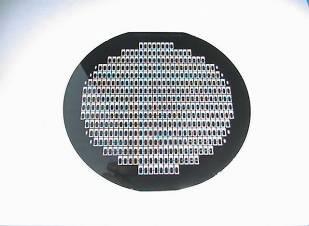
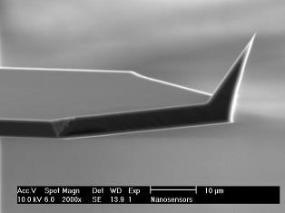
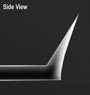
2 Introduction NANOSENSORS has developed a simple and low-budget controller for operation of Akiyama-Probe. In this document, detailed information of the controller is disclosed for those who would like to make an own setup by themselves. This is an additional customer service and only the technical information is provided. NANOSENSORS does not provide any of the products mentioned in this guide. Some contents in this guide may not apply to your specific setup. Please use this guide as a general reference only. Akiyama-Probe Since 2006 Preamp + Probe holder Akiyama-Probe is a patented technology. Self-oscillation + PLL board
3 to Microscope Self-oscillation and simple PLL circuit Preamp All resistors and capacitors may have to be trimmed accordingly. Self-Oscillation Simple PLL 2008, 7, 9 Please use this information on your own responsibility. NANOSENSORS cannot/ will not guarantee or support this setup.


4 Configuration of preamp Sine 1Vp-p IN Attenuation 10:1 20k R1 C1 180p - + 2k R2 A phase shift appears at the resonance frequency if the parasitic capacitance was correctly compensated. A large ground plane directly connected to the positive input of the amp is effective against noise Shorter is Guarding better Connected* 20k VR - + R3 10k C2 1.0p 22M - R4 10k-20k R OPamp: AD8512 Parasitic capacitance compensation C4 100p 10k R6 OUT *The silicon cantilever and tip is electrically connected to the left pad of the ceramic plate. In this configuration, the cantilever and tip should have the virtual ground potential. The output amplitude should be about a half, or a bit less, of the input at the resonance frequency. If not, R5 (or R6) should be adjusted. This is also a trimming point when a stable self-oscillation cannot be obtained. 200 mv /div.


5 Prototype amplifier boards For NanoScope Multimode AFM (Veeco/Bruker) with a custom made holder E.g., CONNECTOR, SMARTCARD, 8WAY CCM LFT ITT CANNON For various applications Spring-pins from a memory card connector, which can be easily pulled out, are used. The metal pieces are soldered on a patterned PCB after cutting off excessive parts. As a stopper, a small solder bump is created. It is recommended to have a large ground plane to improve stability of the oscillation.
6 Functions of self-oscillation circuit Preamp Self-Oscillation to PLL Simple PLL


7 Test of self-oscillation module (1) 10 µs/div, 2 V/div A sine wave of 1Vp-p at 50 khz from function generator x8 amplification (polarity reversed) Half wave If C11 is removed or inserted Sine generator If C11 inserted, C12 removed, C14 short circuit, and R1 ~1.1kΩ, the output signal can be changed +10~-10V DC by R9.


8 Test of self-oscillation module (2) AD633 R13 changes Phase. Amplitude is not changed. The figure below shows a tunable range. The output is the same signal as X1 when Y1 = 10 V. x8 amplified signal Set signal +10V DC by changing R9. Phase shifter 10 µs/div, 2 V/div


9 Test of PLL module 10 µs/div, 2 V/div No good x8 amplified signal As changing R27, the signal wave form changes. It should be like this. No good Square wave 5 V If the signal wave form looks correct and the output at BU2 can be tuned to 0 V by R27, the PLL is correctly set. To measure frequency sensitivity (V/Hz), change the input frequency a little bit, e.g., from khz to khz.
 Frequency shift Df (to microscope)")

 are available")
10 Overview of the DIY controller Oscilloscope (monitor of different signals) Frequency shift Df (to microscope) Amplitude feedback gain: R1 Phase: R13 Amplitude: R9 PLL: R27 This controller was designed in 2008 and only bulky components are used. Today, various SMD (Surface Mount Device) are available and the PCB can be much more compact.
11 Adjustment of the setup (1) Mount a probe and adjust the trimmer (VR) on the preamp as described in the following slides. Make sure that C11, C12, C14 of the main board are all correctly placed. Connect the amplifier board to the main board. Monitor the terminal BU1 by oscilloscope. Select the TF driving signal line (output of IC13a). Amplitude feedback-loop gain: Set R1 2.5 kω, Phase controller : Set R kω, Turn on the power. Amplitude: set the line between R23 and R9 1.5 V. A sin wave should appear on the monitor. Fine-tune the phase adjustment (R13) so that the sin wave has a minimum amplitude. The amplitude feedback-loop gain (R1) should be set as high as possible, but low enough to keep the signal stable. The tip vibration amplitude can be changed by the amplitude adjustment (R9). BU1: Oscilloscope (monitor of different signals)
12 Adjustment of the setup (2) BU1: Oscilloscope (monitor of different signals) BU2: Frequency shift Df (to microscope) Select DET/OUT terminal of XR2212 to appear on BU1. Simultaneously monitor BU2 on oscilloscope. Turn PLL (R27) until a small triangular wave appears at BU1 and 0V DC appears at BU2. The PLL is now correctly set. If the resonance frequency increases, the signal at BU2 also increases. If the signal is not stable, change values of the amplitude feedback-loop gain (R1) and/or the amplitude adjustment (R9) and try again. The self-oscillation frequency should be approximately the same value as the one obtained in the tuning step of the preamp board. Please also consult the other guides from Akiyama- Probe website for successful operation.
 on the board so that the peak becomes almost symmetric.")
13 Adjustment of amplifier board (1) Gain/Phase, Lock-in, etc. Ref. Test If a parameter analyzer (Gain-phase, Lock-in amplifier, etc.) is available. Find a peak by sweeping the frequency. Adjust the VR (or VC) on the board so that the peak becomes almost symmetric. In this condition, the parasitic capacitance around the probe is mostly compensated and only the piezoelectric current is amplified. Sine generator Oscilloscope If a sine wave generator with frequency sweep function and an oscilloscope are available. Start a frequency sweep of the sine wave generator: e.g., center frequency = resonance frequency of the probe, bandwidth = 2 khz, amplitude = 1 V peakpeak, sweeping time = 5 seconds. Set the time axis of the oscilloscope, e.g., 500 ms/div, so that one cycle of the frequency sweep can be monitored. If a peak is found, make the sweep range narrower, e.g., 1 khz, if not, slightly change the center frequency. Adjust the VR (or VC) on the board.
14 amplitude Adjustment of amplifier board (2) Sine generator optimum (symmetric) Multimeter DC V If a sine wave generator with NO frequency sweep function and a multimeter (or an oscilloscope) are available. Set the frequency from the generator at the expected sensor resonance. Precisely adjust the frequency to obtain a maximum amplitude (measure on the multimeter). Take a note of the frequency and the amplitude. Slightly turn the VR (or VC) on the board to one direction. Adjust the frequency and find a maximum amplitude again. Repeat this step if you obtain a smaller amplitude than before. If the amplitude is increased, turn the trimmer to the other direction. The optimum setting is at the point where the amplitude is at its minimum (see the figure below). Note that the amplitude change is usually very small. frequency Each time when a probe is exchanged, it is advised to readjust the tuning to obtain the best performance.


15 Commercial controller If a completed controller is desired, please consider to purchase Tuning Fork Sensor Controller, commercialized by NanoAndMore. Only the preamp + probe holder board (picture below) is also available. Other comanies are also selling high performance contollers and PLLs. Please check Akiyama-Probe website.
16 THANK YOU FOR YOUR INTEREST


17 NANOSENSORS NANOSENSORS Neuchatel Switzerland NANOSENSORS is a NANOSENSORS trademark of NanoWorld is a trademark AG - Copyright of NanoWorld by NanoWorld AG -AG Copyright by NanoWorld AG
Akiyama-Probe (A-Probe) technical guide This technical guide presents: how to make a proper setup for operation of Akiyama-Probe.
 technical guide This technical guide presents: how to make a proper setup for operation of Akiyama-Probe.") Akiyama-Probe (A-Probe) technical guide This technical guide presents: how to make a proper setup for operation of Akiyama-Probe. Version: 2.0 Introduction To benefit from the advantages of Akiyama-Probe,
Akiyama-Probe (A-Probe) technical guide This technical guide presents: how to make a proper setup for operation of Akiyama-Probe. Version: 2.0 Introduction To benefit from the advantages of Akiyama-Probe,
Akiyama-Probe (A-Probe) guide
 guide") Akiyama-Probe (A-Probe) guide This guide presents: what is Akiyama-Probe, how it works, and what you can do Dynamic mode AFM Version: 2.0 Introduction NANOSENSORS Akiyama-Probe (A-Probe) is a self-sensing
Akiyama-Probe (A-Probe) guide This guide presents: what is Akiyama-Probe, how it works, and what you can do Dynamic mode AFM Version: 2.0 Introduction NANOSENSORS Akiyama-Probe (A-Probe) is a self-sensing
Akiyama-Probe (A-Probe) guide
 guide") Akiyama-Probe (A-Probe) guide This guide presents: what is Akiyama-Probe, how it works, and its performance. Akiyama-Probe is a patented technology. Version: 2009-03-23 Introduction NANOSENSORS Akiyama-Probe
Akiyama-Probe (A-Probe) guide This guide presents: what is Akiyama-Probe, how it works, and its performance. Akiyama-Probe is a patented technology. Version: 2009-03-23 Introduction NANOSENSORS Akiyama-Probe
DIY Function Generator XR2206
 DIY Function Generator XR2206 20Hz 100KHz http://radiohobbystore.com Components List: Resistors: R1, R2 1% Metal Film 5K1 R4 1% Metal Film 10K R5 1% Metal Film 3K R10 5% Carbon Film 10R R3, R9 Potentiometer
Sapphire Instruments Co., Ltd. Calibration Procedure of SI-9101
 Sapphire Instruments Co., Ltd. Calibration Procedure of SI-9101 1. How to open the case, please follow the steps. 1.1 Remove the battery lid. 1.2 You will see the two screws and loosen them. Fig. 1 1.3
UNIVERSITY OF NORTH CAROLINA AT CHARLOTTE Department of Electrical and Computer Engineering
 UNIVERSITY OF NORTH CAROLINA AT CHARLOTTE Department of Electrical and Computer Engineering EXPERIMENT 7 PHASE LOCKED LOOPS OBJECTIVES The purpose of this lab is to familiarize students with the operation
Chapter 9: Operational Amplifiers
 Chapter 9: Operational Amplifiers The Operational Amplifier (or op-amp) is the ideal, simple amplifier. It is an integrated circuit (IC). An IC contains many discrete components (resistors, capacitors,
Application Note. ACT5028 Resolver-To-Digital Converter (RDC) Evaluation Board. Application Note AN5028-1
 Evaluation Board. Application Note AN5028-1") Application Note ACT5028 Resolver-To-Digital Converter (RDC) Evaluation Board Scope: This application note is to aid in the support of testing and evaluation of the ACT5028 Resolver to Digital (RDC) Converter
Application Note ACT5028 Resolver-To-Digital Converter (RDC) Evaluation Board Scope: This application note is to aid in the support of testing and evaluation of the ACT5028 Resolver to Digital (RDC) Converter
Experiment 8 Frequency Response
 Experiment 8 Frequency Response W.T. Yeung, R.A. Cortina, and R.T. Howe UC Berkeley EE 105 Spring 2005 1.0 Objective This lab will introduce the student to frequency response of circuits. The student will
WESTREX RA-1712 PHOTOGRAPHIC SOUND RECORD ELECTRONICS
 INTRODUCTION The RA-1712 solid state Record Electronics is an integrated system for recording photographic sound tracks on a Westrex photographic sound recorder. It accepts a 600Ω input signal level from
User s Manual ISL71218MEVAL1Z. User s Manual: Evaluation Board. High Reliability Space
 User s Manual ISL71218MEVAL1Z User s Manual: Evaluation Board High Reliability Space Rev. Aug 217 USER S MANUAL ISL71218MEVAL1Z Evaluation Board UG139 Rev.. 1. Overview The ISL71218MEVAL1Z evaluation platform
Optimal Preamp for Tuning Fork signal detection Scanning Force Microscopy. Kristen Fellows and C.L. Jahncke St. Lawrence University
 Optimal Preamp for Tuning Fork signal detection Scanning Force Microscopy Kristen Fellows and C.L. Jahncke St. Lawrence University H. D. Hallen North Carolina State University Abstract In scanning probe
Characteristics of Crystal. Piezoelectric effect of Quartz Crystal
 Characteristics of Crystal Piezoelectric effect of Quartz Crystal The quartz crystal has a character when the pressure is applied to the direction of the crystal axis, the electric change generates on
Exercise 2: FM Detection With a PLL
 Phase-Locked Loop Analog Communications Exercise 2: FM Detection With a PLL EXERCISE OBJECTIVE When you have completed this exercise, you will be able to explain how the phase detector s input frequencies
Experiment Topic : FM Modulator
 7-1 Experiment Topic : FM Modulator 7.1: Curriculum Objectives 1. To understand the characteristics of varactor diodes. 2. To understand the operation theory of voltage controlled oscillator (VCO). 3.
1) Consider the circuit shown in figure below. Compute the output waveform for an input of 5kHz
 Consider the circuit shown in figure below. Compute the output waveform for an input of 5kHz") ) Consider the circuit shown in figure below. Compute the output waveform for an input of 5kHz Solution: a) Input is of constant amplitude of 2 V from 0 to 0. ms and 2 V from 0. ms to 0.2 ms. The output
) Consider the circuit shown in figure below. Compute the output waveform for an input of 5kHz Solution: a) Input is of constant amplitude of 2 V from 0 to 0. ms and 2 V from 0. ms to 0.2 ms. The output
Lab Exercise # 9 Operational Amplifier Circuits
 Objectives: THEORY Lab Exercise # 9 Operational Amplifier Circuits 1. To understand how to use multiple power supplies in a circuit. 2. To understand the distinction between signals and power. 3. To understand
FFP-C Fiber Fabry-Perot Controller OPERATING INSTRUCTIONS. Version 1.0 MICRON OPTICS, INC.
 FFP-C Fiber Fabry-Perot Controller OPERATING INSTRUCTIONS Version 1.0 MICRON OPTICS, INC. 1852 Century Place NE Atlanta, GA 30345 USA Tel (404) 325-0005 Fax (404) 325-4082 www.micronoptics.com Page 2 Table
Summer 2015 Examination
 Summer 2015 Examination Subject Code: 17445 Model Answer Important Instructions to examiners: 1) The answers should be examined by key words and not as word-to-word as given in the model answer scheme.
ECE 203 LAB 6: INVERTED PENDULUM
 Version 1.1 1 of 15 BEFORE YOU BEGIN EXPECTED KNOWLEDGE Basic Circuit Analysis EQUIPMENT AFG Oscilloscope Programmable Power Supply MATERIALS Three 741 Opamps TIP41 NPN power transistor TIP42 PNP power
University of Michigan EECS 311: Electronic Circuits Fall 2009 LAB 2 NON IDEAL OPAMPS
 University of Michigan EECS 311: Electronic Circuits Fall 2009 LAB 2 NON IDEAL OPAMPS Issued 10/5/2008 Pre Lab Completed 10/12/2008 Lab Due in Lecture 10/21/2008 Introduction In this lab you will characterize
VC528 ST2+ RV1 CMRR Trimmer
 VC528 ST2+ RV1 CMRR Trimmer Now that you have completed the build of your VC528 ST2+ module, we need to calibrate and adjust the RV1 trimmer potentiometer for optimum CMRR. This must be done before you
TOP VIEW REFERENCE VOLTAGE ADJ V OUT
 Rev 1; 8/6 EVALUATION KIT AVAILABLE Electronically Programmable General Description The is a nonvolatile (NV) electronically programmable voltage reference. The reference voltage is programmed in-circuit
150mA, Low-Dropout Linear Regulator with Power-OK Output
 9-576; Rev ; /99 5mA, Low-Dropout Linear Regulator General Description The low-dropout (LDO) linear regulator operates from a +2.5V to +6.5V input voltage range and delivers up to 5mA. It uses a P-channel
12kHz LIF Converter V2.43 9Mhz version
 12kHz LIF Converter V2.43 9Mhz version Please Note: This document supersedes all previously released documents and drawings on the LIF subject. This is the latest and most up-to-date document at this time.
Chapter 14 FSK Demodulator
 Chapter 14 FSK Demodulator 14-1 : Curriculum Objectives 1. To understand the operation theory of FSK demodulator. 2. To implement the FSK detector circuit by using PLL. 3. To understand the operation theory
Low Cost, Precision JFET Input Operational Amplifiers ADA4000-1/ADA4000-2/ADA4000-4
 Low Cost, Precision JFET Input Operational Amplifiers ADA-/ADA-/ADA- FEATURES High slew rate: V/μs Fast settling time Low offset voltage:.7 mv maximum Bias current: pa maximum ± V to ±8 V operation Low
MK VCXO-BASED FRAME CLOCK FREQUENCY TRANSLATOR. Features. Description. Block Diagram DATASHEET. Pullable Crystal
 DATASHEET MK2059-01 Description The MK2059-01 is a VCXO (Voltage Controlled Crystal Oscillator) based clock generator that produces common telecommunications reference frequencies. The output clock is
PCI-EXPRESS CLOCK SOURCE. Features
 DATASHEET ICS557-01 Description The ICS557-01 is a clock chip designed for use in PCI-Express Cards as a clock source. It provides a pair of differential outputs at 100 MHz in a small 8-pin SOIC package.
10 Things to Consider when Acquiring a Nanopositioning System
 10 Things to Consider when Acquiring a Nanopositioning System There are many factors to consider when looking for nanopositioning piezo stages. This article will help explain some items that are important
Project Report Designing Wein-Bridge Oscillator
 Abu Dhabi University EEN 360 - Electronic Devices and Circuits II Project Report Designing Wein-Bridge Oscillator Author: Muhammad Obaidullah 03033 Bilal Arshad 0929 Supervisor: Dr. Riad Kanan Section
easypll UHV Preamplifier Reference Manual
 easypll UHV Preamplifier Reference Manual 1 Table of Contents easypll UHV-Pre-Amplifier for Tuning Fork 2 Theory... 2 Wiring of the pre-amplifier... 4 Technical specifications... 5 Version 1.1 BT 00536
Amplification. Objective. Equipment List. Introduction. The objective of this lab is to demonstrate the basic characteristics an Op amplifier.
 Amplification Objective The objective of this lab is to demonstrate the basic characteristics an Op amplifier. Equipment List Introduction Computer running Windows (NI ELVIS installed) National Instruments
Operational Amplifiers
 Questions Easy Operational Amplifiers 1. Which of the following statements are true? a. An op-amp has two inputs and three outputs b. An op-amp has one input and two outputs c. An op-amp has two inputs
PB63 PB63A. Dual Power Booster Amplifier PB63
 Dual Power Booster Amplifier A FEATURES Wide Supply Range ± V to ±75 V High Output Current Up to 2 A Continuous Programmable Gain High Slew Rate 1 V/µs Typical Programmable Output Current Limit High Power
MK LOW PHASE NOISE T1/E1 CLOCK GENERATOR. Features. Description. Block Diagram DATASHEET. Pullable Crystal
 DATASHEET LOW PHASE NOISE T1/E1 CLOCK ENERATOR MK1581-01 Description The MK1581-01 provides synchronization and timing control for T1 and E1 based network access or multitrunk telecommunication systems.
77 GHz VCO for Car Radar Systems T625_VCO2_W Preliminary Data Sheet
 77 GHz VCO for Car Radar Systems Preliminary Data Sheet Operating Frequency: 76-77 GHz Tuning Range > 1 GHz Output matched to 50 Ω Application in Car Radar Systems ESD: Electrostatic discharge sensitive
TOP VIEW. OUTPUT PRESET 2.5V TO 5V 200mA SHDN 3 4 BP GND. Maxim Integrated Products 1
 19-2584; Rev ; 1/2 Low-Noise, Low-Dropout, 2mA General Description The low-noise, low-dropout linear regulator operates from a 2.5V to 6.5V input and delivers up to 2mA. Typical output noise is 3µV RMS,
Enpirion EN6360QI 8A DC/DC Converter w/integrated Inductor Evaluation Board
 January 0 Enpirion EN660QI 8 DC/DC Converter w/integrated Inductor Evaluation Board Introduction Thank you for choosing Enpirion, the source for Ultra small foot print power converter products! The EN660QI
PS MHz 75dB Logarithmic/Limiting Amplifier
 500MHz 75dB Logarithmic/Limiting Amplifier FEATURES 75dB Dynamic Range Surface Mount SO Package Adjustable Log Slope and Offset 0dBm RF Limiting Output 60dBm Limiting Range 2V Video Output Range Low Power
Analog Circuits and Systems
 Analog Circuits and Systems Prof. K Radhakrishna Rao Lecture 31: Waveform Generation 1 Review Phase Locked Loop (self tuned filter) 2 nd order High Q low-pass output phase compared with the input 90 phase
Single-Phase Grid-Tied Inverter (PWM Rectifier/Inverter)
") Exercise 2 Single-Phase Grid-Tied Inverter (PWM Rectifier/Inverter) EXERCISE OBJECTIVE When you have completed this exercise, you will be familiar with the singlephase grid-tied inverter. DISCUSSION OUTLINE
Exercise 2 Single-Phase Grid-Tied Inverter (PWM Rectifier/Inverter) EXERCISE OBJECTIVE When you have completed this exercise, you will be familiar with the singlephase grid-tied inverter. DISCUSSION OUTLINE
Not Recommended for New Designs
 Not Recommended for New Designs This product was manufactured for Maxim by an outside wafer foundry using a process that is no longer available. It is not recommended for new designs. The data sheet remains
SG1524/SG2524/SG3524 REGULATING PULSE WIDTH MODULATOR DESCRIPTION FEATURES HIGH RELIABILITY FEATURES - SG1524 BLOCK DIAGRAM
 SG54/SG54/SG54 REGULATING PULSE WIDTH MODULATOR DESCRIPTION This monolithic integrated circuit contains all the control circuitry for a regulating power supply inverter or switching regulator. Included
Faculty of Engineering, Thammasat University
 Faculty of Engineering, Thammasat University Experiment 6: Oscilloscope (For room 506) Objectives: 1. To familiarize you with the Oscilloscope and Function Generator User Manual: Oscilloscope 1 5 9 4 7
30 V, High Speed, Low Noise, Low Bias Current, JFET Operational Amplifier ADA4627-1/ADA4637-1
 3 V, High Speed, Low Noise, Low Bias Current, JFET Operational Amplifier /ADA4637- FEATURES Low offset voltage: 2 µv maximum Offset drift: µv/ C typical Very low input bias current: 5 pa maximum Extended
ML12561 Crystal Oscillator
 ML56 Crystal Oscillator Legacy Device: Motorola MC56 The ML56 is the military temperature version of the commercial ML06 device. It is for use with an external crystal to form a crystal controlled oscillator.
Quadrature Oscillator (Part 1) An active inductor
 An active inductor") Quadrature Oscillator (Part 1) A quadrature oscillator produces two sinewaves with 90 phase difference between them. These are useful to pan signals (particularly in a quadraphonic environment), or to
Quadrature Oscillator (Part 1) A quadrature oscillator produces two sinewaves with 90 phase difference between them. These are useful to pan signals (particularly in a quadraphonic environment), or to
PHYS 536 The Golden Rules of Op Amps. Characteristics of an Ideal Op Amp
 PHYS 536 The Golden Rules of Op Amps Introduction The purpose of this experiment is to illustrate the golden rules of negative feedback for a variety of circuits. These concepts permit you to create and
Exp. #2-6 : Measurement of the Characteristics of,, and Circuits by Using an Oscilloscope
 PAGE 1/14 Exp. #2-6 : Measurement of the Characteristics of,, and Circuits by Using an Oscilloscope Student ID Major Name Team No. Experiment Lecturer Student's Mentioned Items Experiment Class Date Submission
DATASHEET HA Features. Applications. Ordering Information. Pinout. 400MHz, Fast Settling Operational Amplifier. FN2897 Rev.5.
 DATASHEET MHz, Fast Settling Operational Amplifier The Intersil is a wideband, very high slew rate, monolithic operational amplifier featuring superior speed and bandwidth characteristics. Bipolar construction
Chapter 9: Operational Amplifiers
 Chapter 9: Operational Amplifiers The Operational Amplifier (or op-amp) is the ideal, simple amplifier. It is an integrated circuit (IC). An IC contains many discrete components (resistors, capacitors,
HF Amateur SSB Receiver
 HF Amateur SSB Receiver PCB Set for radio club project http://rhelectronics.net PCB for DIY HF Amateur SSB Receiver 20M The receiver is a simple syperheterodyne type with quartz crystal filter. The circuit
HMC4069LP4E FREQUENCY DIVIDERS AND DETECTORS - SMT. Typical Applications. General Description. Functional Diagram
 Typical Applications The HMC4069LPE is ideal for: Point-to-Point Radios Satellite Communication Systems Military Applications Sonet Clock Generation General Description Functional Diagram Features Ultra
Exercise 2: Demodulation (Quadrature Detector)
") Analog Communications Angle Modulation and Demodulation Exercise 2: Demodulation (Quadrature Detector) EXERCISE OBJECTIVE When you have completed this exercise, you will be able to explain demodulation
Analog Communications Angle Modulation and Demodulation Exercise 2: Demodulation (Quadrature Detector) EXERCISE OBJECTIVE When you have completed this exercise, you will be able to explain demodulation
Description of a Function Generator Instrument
 Description of a Function Generator Instrument A function generator is usually a piece of electronic test equipment that is used to generate different types of electrical waveforms over a wide range of
Electronics I. laboratory measurement guide
 Electronics I. laboratory measurement guide Andras Meszaros, Mark Horvath 2015.02.01. 5. Measurement Basic circuits with operational amplifiers 2015.02.01. In this measurement you will need both controllable
Lab Equipment EECS 311 Fall 2009
 Lab Equipment EECS 311 Fall 2009 Contents Lab Equipment Overview pg. 1 Lab Components.. pg. 4 Probe Compensation... pg. 8 Finite Instrumentation Impedance. pg.10 Simulation Tools..... pg. 10 1 - Laboratory
HMC3716LP4E FREQUENCY DIVIDERS AND DETECTORS - SMT. Typical Applications. General Description. Functional Diagram
 Typical Applications The HMC3716LPE is ideal for: Point-to-Point Radios Satellite Communication Systems Military Applications Sonet Clock Generation General Description Functional Diagram Features Ultra
ECE Lab #4 OpAmp Circuits with Negative Feedback and Positive Feedback
 ECE 214 Lab #4 OpAmp Circuits with Negative Feedback and Positive Feedback 20 February 2018 Introduction: The TL082 Operational Amplifier (OpAmp) and the Texas Instruments Analog System Lab Kit Pro evaluation
FSK DEMODULATOR / TONE DECODER
 FSK DEMODULATOR / TONE DECODER GENERAL DESCRIPTION The is a monolithic phase-locked loop (PLL) system especially designed for data communications. It is particularly well suited for FSK modem applications,
MHz 58 db 1 KW RF Amplifier (EDA 00097)
") EUROPEAN ORGANIZATION FOR NUCLEAR RESEARCH CERN A&B DEPARTMENT AB-Note-2004-029 RF 0.2-10 58 1 KW RF Amplifier (EDA 00097) M. Paoluzzi 25 th March 2004 Geneva, Switzerland 1 1. DESCRIPTION 1.1. GENERAL
EUROPEAN ORGANIZATION FOR NUCLEAR RESEARCH CERN A&B DEPARTMENT AB-Note-2004-029 RF 0.2-10 58 1 KW RF Amplifier (EDA 00097) M. Paoluzzi 25 th March 2004 Geneva, Switzerland 1 1. DESCRIPTION 1.1. GENERAL
The Tuned Circuit. Aim of the experiment. Circuit. Equipment and components. Display of a decaying oscillation. Dependence of L, C and R.
 The Tuned Circuit Aim of the experiment Display of a decaying oscillation. Dependence of L, C and R. Circuit Equipment and components 1 Rastered socket panel 1 Resistor R 1 = 10 Ω, 1 Resistor R 2 = 1 kω
Table of Contents Lesson One Lesson Two Lesson Three Lesson Four Lesson Five PREVIEW COPY
 Oscillators Table of Contents Lesson One Lesson Two Lesson Three Introduction to Oscillators...3 Flip-Flops...19 Logic Clocks...37 Lesson Four Filters and Waveforms...53 Lesson Five Troubleshooting Oscillators...69
AVL-10000T AUDIO VIDEO LINK TRANSMITTER TECHNICAL MANUAL
 AVL-10000T AUDIO VIDEO LINK TRANSMITTER TECHNICAL MANUAL Document : AVL-10000T Version: 1.00 Author: Henry S Date: 25 July 2008 This module contains protection circuitry to guard against damage due to
nanopower Op Amp in a Tiny 6-Bump WLP
 EVALUATION KIT AVAILABLE MAX4464 General Description The MAX4464 is an ultra-small (6-bump WLP) op amp that draws only 75nA of supply current. It operates from a single +.8V to +5.5V supply and features
Application Note 5525
 Using the Wafer Scale Packaged Detector in 2 to 6 GHz Applications Application Note 5525 Introduction The is a broadband directional coupler with integrated temperature compensated detector designed for
KM4110/KM mA, Low Cost, +2.7V & +5V, 75MHz Rail-to-Rail Amplifiers
 + + www.fairchildsemi.com KM411/KM41.5mA, Low Cost, +.7V & +5V, 75MHz Rail-to-Rail Amplifiers Features 55µA supply current 75MHz bandwidth Power down to I s = 33µA (KM41) Fully specified at +.7V and +5V
When you have completed this exercise, you will be able to relate the gain and bandwidth of an op amp
 Op Amp Fundamentals When you have completed this exercise, you will be able to relate the gain and bandwidth of an op amp In general, the parameters are interactive. However, in this unit, circuit input
An Analog Phase-Locked Loop
 1 An Analog Phase-Locked Loop Greg Flewelling ABSTRACT This report discusses the design, simulation, and layout of an Analog Phase-Locked Loop (APLL). The circuit consists of five major parts: A differential
XR-2206 Monolithic Function Generator
 ...the analog plus company TM XR-0 Monolithic Function Generator FEATURES Low-Sine Wave Distortion 0.%, Typical Excellent Temperature Stability 0ppm/ C, Typical Wide Sweep Range 000:, Typical Low-Supply
PART MAX4144ESD MAX4146ESD. Typical Application Circuit. R t IN- IN+ TWISTED-PAIR-TO-COAX CABLE CONVERTER
 9-47; Rev ; 9/9 EVALUATION KIT AVAILABLE General Description The / differential line receivers offer unparalleled high-speed performance. Utilizing a threeop-amp instrumentation amplifier architecture,
First Time User Manual
 Fiber Fabry-Perot Tunable Filter FFP-TF2 First Time User Manual Micron Optics Inc. 1852 Century Place NE Atlanta, GA 30345 USA phone 404 325 0005 fax 404 325 4082 www.micronoptics.com Copyright 2009 Micron
PACS Nos v, Fc, Yd, Fs
 A Shear Force Feedback Control System for Near-field Scanning Optical Microscopes without Lock-in Detection J. W. P. Hsu *,a, A. A. McDaniel a, and H. D. Hallen b a Department of Physics, University of
MEMS for RF, Micro Optics and Scanning Probe Nanotechnology Applications
 MEMS for RF, Micro Optics and Scanning Probe Nanotechnology Applications Part I: RF Applications Introductions and Motivations What are RF MEMS? Example Devices RFIC RFIC consists of Active components
Electronics II. 3. measurement : Tuned circuits
 Electronics II. 3. measurement : Tuned circuits This laboratory session involves circuits which contain a double-t (or TT), a passive RC circuit: Figure 1. Double T passive RC circuit module The upper
ICS CLOCK MULTIPLIER AND JITTER ATTENUATOR. Description. Features. Block Diagram DATASHEET
 DATASHEET ICS2059-02 Description The ICS2059-02 is a VCXO (Voltage Controlled Crystal Oscillator) based clock multiplier and jitter attenuator designed for system clock distribution applications. This
Discrete Op-Amp Kit MitchElectronics 2019
 Discrete Op-Amp Kit MitchElectronics 2019 www.mitchelectronics.co.uk CONTENTS Introduction 3 Schematic 4 How It Works 5 Materials 9 Construction 10 Important Information 11 Page 2 INTRODUCTION Even if
ELC224 Final Review (12/10/2009) Name:
 Name:") ELC224 Final Review (12/10/2009) Name: Select the correct answer to the problems 1 through 20. 1. A common-emitter amplifier that uses direct coupling is an example of a dc amplifier. 2. The frequency
ELC224 Final Review (12/10/2009) Name: Select the correct answer to the problems 1 through 20. 1. A common-emitter amplifier that uses direct coupling is an example of a dc amplifier. 2. The frequency
XR-2211 FSK Demodulator/ Tone Decoder
 ...the analog plus company TM XR- FSK Demodulator/ Tone Decoder FEATURES APPLICATIONS June 997-3 Wide Frequency Range, 0.0Hz to 300kHz Wide Supply Voltage Range, 4.5V to 0V HCMOS/TTL/Logic Compatibility
Making Invasive and Non-Invasive Stability Measurements
 Making Invasive and Non-Invasive s Using the Bode 1 and the PICOTEST J2111A Current Injector By Florian Hämmerle & Steve Sandler 21 Picotest.com Visit www.picotest.com for more information. Contact support@picotest.com
 Distributed by: www.jameco.com -00-3- The content and copyrights of the attached material are the property of its owner. ...the analog plus company TM XR-0 Monolithic Function Generator FEATURES Low-Sine
11. Audio Amp. LM386 Low Power Amplifier:
 EECE208 INTRO TO EE LAB Dr. Charles Kim 11. Audio Amp Objectives: The main purpose of this laboratory exercise is to design an audio amplifier based on the LM386 Low Voltage Audio Power Amplifier chip
ECE ECE285. Electric Circuit Analysis I. Spring Nathalia Peixoto. Rev.2.0: Rev Electric Circuits I
 ECE285 Electric Circuit Analysis I Spring 2014 Nathalia Peixoto Rev.2.0: 140124. Rev 2.1. 140813 1 Lab reports Background: these 9 experiments are designed as simple building blocks (like Legos) and students
10: AMPLIFIERS. Circuit Connections in the Laboratory. Op-Amp. I. Introduction
 10: AMPLIFIERS Circuit Connections in the Laboratory From now on you will construct electrical circuits and test them. The usual way of constructing circuits would be to solder each electrical connection
Optimizing Feedforward Compensation In Linear Regulators
 Optimizing Feedforward Compensation In Linear Regulators Introduction All linear voltage regulators use a feedback loop which controls the amount of current sent to the load as required to hold the output
XR-215A Monolithic Phase Locked Loop
 ...the analog plus company TM XR-21A Monolithic Phase Locked Loop FEATURES APPLICATIONS June 1997-3 Wide Frequency Range: 0.Hz to 2MHz Wide Supply Voltage Range: V to 26V Wide Dynamic Range: 300V to 3V,
PART MAX2605EUT-T MAX2606EUT-T MAX2607EUT-T MAX2608EUT-T MAX2609EUT-T TOP VIEW IND GND. Maxim Integrated Products 1
 19-1673; Rev 0a; 4/02 EVALUATION KIT MANUAL AVAILABLE 45MHz to 650MHz, Integrated IF General Description The are compact, high-performance intermediate-frequency (IF) voltage-controlled oscillators (VCOs)
DEPARTMENT OF ELECTRICAL ENGINEERING LAB WORK EE301 ELECTRONIC CIRCUITS
 DEPARTMENT OF ELECTRICAL ENGINEERING LAB WORK EE301 ELECTRONIC CIRCUITS EXPERIMENT : 3 TITLE : Operational Amplifier (Op-Amp) OUTCOME : Upon completion of this unit, the student should be able to: 1. Gain
Single-Supply 42 V System Difference Amplifier AD8205
 Single-Supply 42 V System Difference Amplifier FEATURES Ideal for current shunt applications High common-mode voltage range 2 V to +65 V operating 5 V to +68 V survival Gain = 50 Wide operating temperature
Single-Supply, 42 V System Difference Amplifier AD8206
 Single-Supply, 42 V System Difference Amplifier FEATURES Ideal for current shunt applications High common-mode voltage range 2 V to +65 V operating 25 V to +75 V survival Gain = 20 Wide operating temperature
Bioelectric Signal Analog Front-End Module Electrocardiograph
 ***LOGO*** Bioelectric Signal Analog Front-End Module Electrocardiograph Features Single or Dual Supply Operation Quiescent Current: 220µA at 3.3v Internal Reference Generator with External Override Option
Spectrum analyzer for frequency bands of 8-12, and MHz
 EE389 Electronic Design Lab Project Report, EE Dept, IIT Bombay, November 2006 Spectrum analyzer for frequency bands of 8-12, 12-16 and 16-20 MHz Group No. D-13 Paras Choudhary (03d07012)
MAX8863T/S/R, MAX8864T/S/R. Low-Dropout, 120mA Linear Regulators. General Description. Benefits and Features. Ordering Information.
 General Description The MAX8863T/S/R and low-dropout linear regulators operate from a +2.5V to +6.5V input range and deliver up to 12mA. A PMOS pass transistor allows the low, 8μA supply current to remain
SG2524 SG3524 REGULATING PULSE WIDTH MODULATORS
 SG2524 SG3524 REGULATING PULSE WIDTH MODULATORS COMPLETE PWM POWER CONTROL CIR- CUITRY UNCOMMITTED OUTPUTS FOR SINGLE- ENDED OR PUSH PULL APPLICATIONS LOW STANDBY CURRENT 8mA TYPICAL OPERATION UP TO 300KHz
Chapter 11 ASK Modulator
 Chapter 11 ASK Modulator 11-1 : Curriculum Objectives 1. To understand the operation theory of the amplitude shift keying (ASK) modulation. 2. To understand the signal waveform of the ASK modulation. 3.
Integrated Dual-Axis Gyro IDG-1004
 Integrated Dual-Axis Gyro NOT RECOMMENDED FOR NEW DESIGNS. PLEASE REFER TO THE IDG-25 FOR A FUTIONALLY- UPGRADED PRODUCT APPLICATIONS GPS Navigation Devices Robotics Electronic Toys Platform Stabilization
PDu150CL Ultra-low Noise 150V Piezo Driver with Strain Gauge Feedback
 PDu1CL Ultra-low Noise 1V Piezo Driver with Strain auge Feedback The PDu1CL combines a miniature high-voltage power supply, precision strain conditioning circuit, feedback controller, and ultra-low noise
PDu150CL Ultra low Noise 150V Piezo Driver with Strain Gauge Feedback
 PDu15CL Ultra low Noise 15V Piezo Driver with Strain auge Feedback The PDu15CL combines a miniature high voltage power supply, precision strain conditioning circuit, feedback controller, and ultra low
Enpirion EP5357xUI DC/DC Converter Module Evaluation Board
 Enpirion EP5357xUI DC/DC Converter Module Evaluation Board Introduction Thank you for choosing Altera Enpirion power products! This application note describes how to test the EP5357xUI (EP5357LUI, EP5357HUI)