Synchronization control of DC motors through adaptive disturbance cancellation
|
|
|
- Colleen Holly Gilbert
- 6 years ago
- Views:
Transcription

1 University of Rome Tor Vergata Department of Industrial Engineering Bachelor's Degree in Engineering Sciences Synchronization control of DC motors through adaptive disturbance cancellation -Implementation issuescandidate: C. Valentini Supervisor: C.M. Verrelli Thesis Advisor: M. Tiberti July, the 26th, 2016
2 A brief abstract... A different interpretation of a mater/slave controller Description of the implementation of the algorithm Presentation of the experimental results 1
3 The model of the DC motor 2
4 The model of the DC motor The current control input... 2
5 The model of the DC motor The current control input... Stabilizing action Reconstruction action 2
6 The control signal in the Laplace domain... 3
7 The control signal in the Laplace domain... Block diagram of the controller 3
8 The control signal in the Laplace domain... Block diagram of the controller 3
9 The control signal in the Laplace domain... Block diagram of the controller 3
10 The control signal in the Laplace domain... Block diagram of the controller 3
11 Stabilizing action: a PD-like interpretation... 4
12 Stabilizing action: a PD-like interpretation... 4
13 Stabilizing action: a PD-like interpretation... Dynamics of the reduced order observer 4
14 From the mathematical description of the algorithm to its actual implementation 5


15 From the mathematical description of the algorithm to its actual implementation 5 4
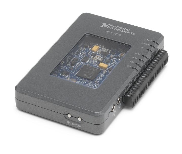
16 NI myrio device 6

17 NI myrio device The FPGA chip 6
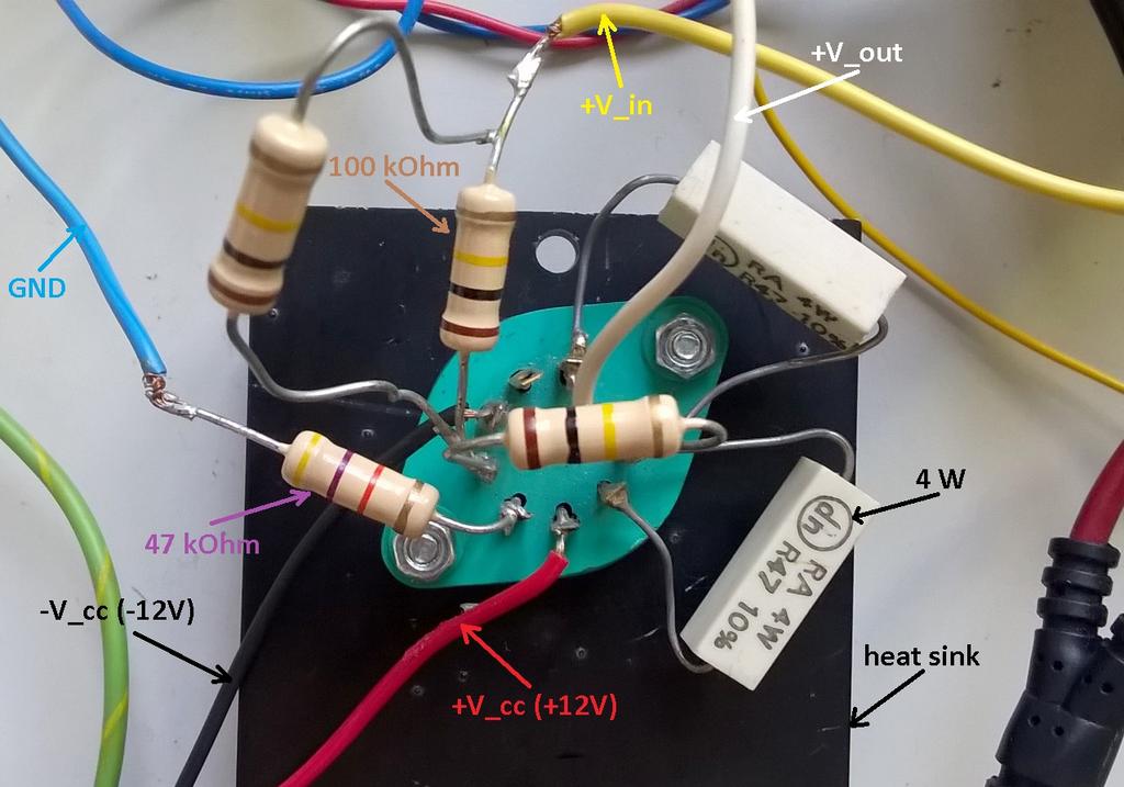
18 The DC motor used in the experiments 7
19 The DC motor used in the experiments HP rotary encoder GND +V in RS
20 Flow of the experiment 8
21 Flow of the experiment 8
22 Flow of the experiment 8
23 Flow of the experiment 8
24 Flow of the experiment 8
25 Flow of the experiment 8

26 Flow of the experiment 8
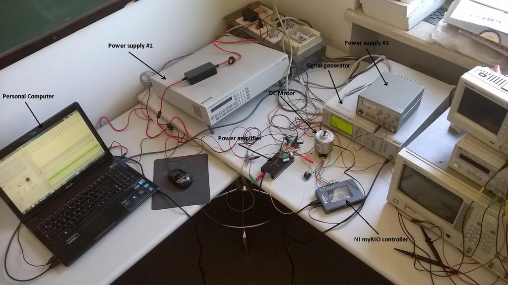
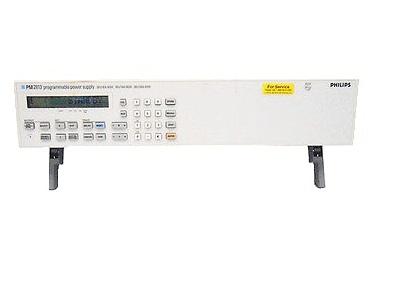
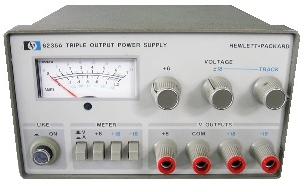
27 Experimental set-up 9
28 Main LabVIEW program loaded on the controller 10
29 Main LabVIEW program loaded on the controller Control subsystems: Subsystem for the conversion of the reference signal, from Volts to radiants 10
30 Main LabVIEW program loaded on the controller Control subsystems: Subsystem for the conversion of the reference signal, from Volts to radiants Subsystem for the acquisition of the encoder steps and their conversion to an angle (in radiants) 10
31 Main LabVIEW program loaded on the controller Control subsystems: Subsystem for the conversion of the reference signal, from Volts to radiants Subsystem for the acquisition of the encoder steps and their conversion to an angle (in radiants) Subsystem implementing the whole controller 10
32 Main LabVIEW program loaded on the controller Control subsystems: Subsystem for the conversion of the reference signal, from Volts to radiants Subsystem for the acquisition of the encoder steps and their conversion to an angle (in radiants) Subsystem implementing the whole controller Subsystem containing the PI control block generating the voltage input for the power amplifier 10


33 An exploded overview of the program modules Control subsystems: Subsystem for the conversion of the reference signal, from Volts to radiants Subsystem for the acquisition of the encoder steps and their conversion to an angle (in radiants) Subsystem implementing the whole controller Subsystem containing the PI control block generating the voltage input for the power amplifier 11
34 Computation of the parameters through trial and error method PD-like control block (the position tracking) 12
35 Computation of the parameters through trial and error method PD-like control block (the position tracking) PI control block (the current feedback) 12
36 Computation of the parameters through trial and error method PD-like control block (the position tracking) PI control block (the current feedback) Frequency observer 12
37 Computation of the parameters through trial and error method PD-like control block (the position tracking) PI control block (the current feedback) Frequency observer Gain of the internal model 12
38 Experimental results Position tracking (initial transient) Reference waveform (freq. = 0.25Hz) Tracking waveform Frequency reconstruction error 13
39 Experimental results Position tracking (initial transient) Reference waveform (freq. = 0.25Hz) Tracking waveform 0 Frequency reconstruction error 13
40 Experimental results Position tracking (initial transient) Reference waveform (freq. = 0.25Hz) Tracking waveform 0 Frequency reconstruction error 13
41 Experimental results Reaction to frequency changes Reference waveform (freq. = 0.25 to 0.5 to 0.35 Hz) Tracking waveform Position tracking error Frequency reconstruction error 14
 Tracking waveform Position tracking error 0 0 Frequency reconstruction error 14")
42 Experimental results Reaction to frequency changes 0.02 rad 1 rad Reference waveform (freq. = 0.25 to 0.5 to 0.35 Hz) Tracking waveform Position tracking error 0 0 Frequency reconstruction error 14
43 Practical demonstration Control of an actual DC motor 15
44 Conclusions The algorithm is easily implementable The algorithm structure is flexible and it can be adapted to the control of any DC motor (with a relatively easy tuning of the parameters) The controller performance in terms of velocity of the reference signal frequency reconstruction action is satisfactory The combined action of the frequency reconstruction and the PD-like position control is an extremely efficient strategy for the removal of a sinusoidal disturbance characterized by a single frequency 16
45 Thank you for your attention!
Figure 1.1: Quanser Driving Simulator
 1 INTRODUCTION The Quanser HIL Driving Simulator (QDS) is a modular and expandable LabVIEW model of a car driving on a closed track. The model is intended as a platform for the development, implementation
DEGREE: Biomedical Engineering YEAR: TERM: 1
 COURSE: Control Engineering DEGREE: Biomedical Engineering YEAR: TERM: 1 La asignatura tiene 14 sesiones que se distribuyen a lo largo de 7 semanas. Los dos laboratorios puede situarse en cualquiera de
Digital Control of MS-150 Modular Position Servo System
 IEEE NECEC Nov. 8, 2007 St. John's NL 1 Digital Control of MS-150 Modular Position Servo System Farid Arvani, Syeda N. Ferdaus, M. Tariq Iqbal Faculty of Engineering, Memorial University of Newfoundland
ME375 Lab Project. Bradley Boane & Jeremy Bourque April 25, 2018
 ME375 Lab Project Bradley Boane & Jeremy Bourque April 25, 2018 Introduction: The goal of this project was to build and program a two-wheel robot that travels forward in a straight line for a distance
Enhanced performance of delayed teleoperator systems operating within nondeterministic environments
 University of Wollongong Research Online University of Wollongong Thesis Collection 1954-2016 University of Wollongong Thesis Collections 2010 Enhanced performance of delayed teleoperator systems operating
Laboratory set-up for Real-Time study of Electric Drives with Integrated Interfaces for Test and Measurement
 Laboratory set-up for Real-Time study of Electric Drives with Integrated Interfaces for Test and Measurement Fong Mak, Ram Sundaram, Varun Santhaseelan, and Sunil Tandle Gannon University, mak001@gannon.edu,
Experiment 1. Speed control of a DC motor with an inner current loop
 he University of New South Wales School of Electrical Engineering & elecommunications ELEC463 - ELECRIC RIVE SYSEMS Experiment. Speed control of a C motor with an inner current loop. Introduction In this
Controlling an AC Motor
 Controlling an AC Motor Elias Badillo Ibarra James Smith December 7, 2010 EE 554 Embedded Control Systems Abstract The goal of this project was to implement a PID motor controller to control velocity in
DC SERVO MOTOR CONTROL SYSTEM
 DC SERVO MOTOR CONTROL SYSTEM MODEL NO:(PEC - 00CE) User Manual Version 2.0 Technical Clarification /Suggestion : / Technical Support Division, Vi Microsystems Pvt. Ltd., Plot No :75,Electronics Estate,
Motor Modeling and Position Control Lab 3 MAE 334
 Motor ing and Position Control Lab 3 MAE 334 Evan Coleman April, 23 Spring 23 Section L9 Executive Summary The purpose of this experiment was to observe and analyze the open loop response of a DC servo
 EC6405 - CONTROL SYSTEM ENGINEERING Questions and Answers Unit - II Time Response Analysis Two marks 1. What is transient response? The transient response is the response of the system when the system
Rotary Motion Servo Plant: SRV02. Rotary Experiment #02: Position Control. SRV02 Position Control using QuaRC. Student Manual
 Rotary Motion Servo Plant: SRV02 Rotary Experiment #02: Position Control SRV02 Position Control using QuaRC Student Manual Table of Contents 1. INTRODUCTION...1 2. PREREQUISITES...1 3. OVERVIEW OF FILES...2
Figure 1: Unity Feedback System. The transfer function of the PID controller looks like the following:
 Islamic University of Gaza Faculty of Engineering Electrical Engineering department Control Systems Design Lab Eng. Mohammed S. Jouda Eng. Ola M. Skeik Experiment 3 PID Controller Overview This experiment
High-speed and High-precision Motion Controller
 High-speed and High-precision Motion Controller - KSMC - Definition High-Speed Axes move fast Execute the controller ( position/velocity loop, current loop ) at high frequency High-Precision High positioning
5 Lab 5: Position Control Systems - Week 2
 5 Lab 5: Position Control Systems - Week 2 5.7 Introduction In this lab, you will convert the DC motor to an electromechanical positioning actuator by properly designing and implementing a proportional
GE 320: Introduction to Control Systems
 GE 320: Introduction to Control Systems Laboratory Section Manual 1 Welcome to GE 320.. 1 www.softbankrobotics.com 1 1 Introduction This section summarizes the course content and outlines the general procedure
Application of Gain Scheduling Technique to a 6-Axis Articulated Robot using LabVIEW R
 Application of Gain Scheduling Technique to a 6-Axis Articulated Robot using LabVIEW R ManSu Kim #,1, WonJee Chung #,2, SeungWon Jeong #,3 # School of Mechatronics, Changwon National University Changwon,
Fundamentals of Servo Motion Control
 Fundamentals of Servo Motion Control The fundamental concepts of servo motion control have not changed significantly in the last 50 years. The basic reasons for using servo systems in contrast to open
PYKC 7 March 2019 EA2.3 Electronics 2 Lecture 18-1
 In this lecture, we will examine a very popular feedback controller known as the proportional-integral-derivative (PID) control method. This type of controller is widely used in industry, does not require
The Discussion of this exercise covers the following points: Angular position control block diagram and fundamentals. Power amplifier 0.
 Exercise 6 Motor Shaft Angular Position Control EXERCISE OBJECTIVE When you have completed this exercise, you will be able to associate the pulses generated by a position sensing incremental encoder with
Project Proposal. Low-Cost Motor Speed Controller for Bradley ECE Department Robots L.C.M.S.C. By Ben Lorentzen
 Project Proposal Low-Cost Motor Speed Controller for Bradley ECE Department Robots L.C.M.S.C. By Ben Lorentzen Advisor Dr. Gary Dempsey Bradley University Department of Electrical Engineering December
Closed Loop Magnetic Levitation Control of a Rotary Inductrack System. Senior Project Proposal. Students: Austin Collins Corey West
 Closed Loop Magnetic Levitation Control of a Rotary Inductrack System Senior Project Proposal Students: Austin Collins Corey West Advisors: Dr. Winfred Anakwa Mr. Steven Gutschlag Date: December 18, 2013
of harmonic cancellation algorithms The internal model principle enable precision motion control Dynamic control
 Dynamic control Harmonic cancellation algorithms enable precision motion control The internal model principle is a 30-years-young idea that serves as the basis for a myriad of modern motion control approaches.
Control Design for Servomechanisms July 2005, Glasgow Detailed Training Course Agenda
 Control Design for Servomechanisms 12 14 July 2005, Glasgow Detailed Training Course Agenda DAY 1 INTRODUCTION TO SYSTEMS AND MODELLING 9.00 Introduction The Need For Control - What Is Control? - Feedback
Effective Teaching Learning Process for PID Controller Based on Experimental Setup with LabVIEW
 Effective Teaching Learning Process for PID Controller Based on Experimental Setup with LabVIEW Komal Sampatrao Patil & D.R.Patil Electrical Department, Walchand college of Engineering, Sangli E-mail :
Lab 23 Microcomputer-Based Motor Controller
 Lab 23 Microcomputer-Based Motor Controller Page 23.1 Lab 23 Microcomputer-Based Motor Controller This laboratory assignment accompanies the book, Embedded Microcomputer Systems: Real Time Interfacing,
Lab 11. Speed Control of a D.C. motor. Motor Characterization
 Lab 11. Speed Control of a D.C. motor Motor Characterization Motor Speed Control Project 1. Generate PWM waveform 2. Amplify the waveform to drive the motor 3. Measure motor speed 4. Estimate motor parameters
Industrial Control Equipment. ACS-1000 Analog Control System
 Analog Control System, covered with many technical disciplines, explicates the central significance of Analog Control System. This applies particularly in mechanical and electrical engineering, and as
Automatic Control Motion control Advanced control techniques
 Automatic Control Motion control Advanced control techniques (luca.bascetta@polimi.it) Politecnico di Milano Dipartimento di Elettronica, Informazione e Bioingegneria Motivations (I) 2 Besides the classical
Design of a Simulink-Based Control Workstation for Mobile Wheeled Vehicles with Variable-Velocity Differential Motor Drives
 Design of a Simulink-Based Control Workstation for Mobile Wheeled Vehicles with Variable-Velocity Differential Motor Drives Kevin Block, Timothy De Pasion, Benjamin Roos, Alexander Schmidt Gary Dempsey
Lecture 9. Lab 16 System Identification (2 nd or 2 sessions) Lab 17 Proportional Control
 Lab 17 Proportional Control") 246 Lecture 9 Coming week labs: Lab 16 System Identification (2 nd or 2 sessions) Lab 17 Proportional Control Today: Systems topics System identification (ala ME4232) Time domain Frequency domain Proportional
246 Lecture 9 Coming week labs: Lab 16 System Identification (2 nd or 2 sessions) Lab 17 Proportional Control Today: Systems topics System identification (ala ME4232) Time domain Frequency domain Proportional
ECE 5670/ Lab 5. Closed-Loop Control of a Stepper Motor. Objectives
 1. Introduction ECE 5670/6670 - Lab 5 Closed-Loop Control of a Stepper Motor Objectives The objective of this lab is to develop and test a closed-loop control algorithm for a stepper motor. First, field
International Journal of Research in Advent Technology Available Online at:
 OVERVIEW OF DIFFERENT APPROACHES OF PID CONTROLLER TUNING Manju Kurien 1, Alka Prayagkar 2, Vaishali Rajeshirke 3 1 IS Department 2 IE Department 3 EV DEpartment VES Polytechnic, Chembur,Mumbai 1 manjulibu@gmail.com
Synchronization in Digital Communications
 Synchronization in Digital Communications Volume 1 Phase-, Frequency-Locked Loops, and Amplitude Control Heinrich Meyr Aachen University of Technology (RWTH) Gerd Ascheid CADIS GmbH, Aachen WILEY A Wiley-lnterscience
UNIVERSITY OF NORTH CAROLINA AT CHARLOTTE Department of Electrical and Computer Engineering
 UNIVERSITY OF NORTH CAROLINA AT CHARLOTTE Department of Electrical and Computer Engineering EXPERIMENT 1 INTRODUCTION TO THE EMONA SIGEX BOARD FOR NI ELVIS OBJECTIVES The purpose of this experiment is
ME451: Control Systems. Course roadmap
 ME451: Control Systems Lecture 20 Root locus: Lead compensator design Dr. Jongeun Choi Department of Mechanical Engineering Michigan State University Fall 2008 1 Modeling Course roadmap Analysis Design
Optimizing Performance Using Slotless Motors. Mark Holcomb, Celera Motion
 Optimizing Performance Using Slotless Motors Mark Holcomb, Celera Motion Agenda 1. How PWM drives interact with motor resistance and inductance 2. Ways to reduce motor heating 3. Locked rotor test vs.
EE 300W 001 Lab 2: Optical Theremin. Cole Fenton Matthew Toporcer Michael Wilson
 EE 300W 001 Lab 2: Optical Theremin Cole Fenton Matthew Toporcer Michael Wilson March 8 th, 2015 2 Abstract This document serves as a design review to document our process to design and build an optical
Chapter 5. Tracking system with MEMS mirror
 Chapter 5 Tracking system with MEMS mirror Up to now, this project has dealt with the theoretical optimization of the tracking servo with MEMS mirror through the use of simulation models. For these models
GE420 Laboratory Assignment 8 Positioning Control of a Motor Using PD, PID, and Hybrid Control
 GE420 Laboratory Assignment 8 Positioning Control of a Motor Using PD, PID, and Hybrid Control Goals for this Lab Assignment: 1. Design a PD discrete control algorithm to allow the closed-loop combination
Hydraulic Actuator Control Using an Multi-Purpose Electronic Interface Card
 Hydraulic Actuator Control Using an Multi-Purpose Electronic Interface Card N. KORONEOS, G. DIKEAKOS, D. PAPACHRISTOS Department of Automation Technological Educational Institution of Halkida Psaxna 34400,
Further Control Systems Engineering
 Unit 54: Unit code Further Control Systems Engineering Y/615/1522 Unit level 5 Credit value 15 Introduction Control engineering is usually found at the top level of large projects in determining the engineering
Latest Control Technology in Inverters and Servo Systems
 Latest Control Technology in Inverters and Servo Systems Takao Yanase Hidetoshi Umida Takashi Aihara. Introduction Inverters and servo systems have achieved small size and high performance through the
High Airflow Pressure Loading Actuator
 Instruction Manual August 22, 2016 Powell Family Structures & Materials Laboratory Professor: David O. Prevatt, PhD TABLE OF CONTENTS 1 Background... 1 1.1 EQUIPMENT SPECIFICATIONS AND CAPABILITIES...
SHOCK RESPONSE SPECTRUM SYNTHESIS VIA DAMPED SINUSOIDS Revision B
 SHOCK RESPONSE SPECTRUM SYNTHESIS VIA DAMPED SINUSOIDS Revision B By Tom Irvine Email: tomirvine@aol.com April 5, 2012 Introduction Mechanical shock can cause electronic components to fail. Crystal oscillators
Variable Frequency AC Source
 Variable Frequency AC Source Functional Requirements List and Performance Specifications Students: Kevin Lemke Matthew Pasternak Advisor: Steven D. Gutschlag Date: November 15, 2013 1 Introduction: Variable
Experiment 3. Performance of an induction motor drive under V/f and rotor flux oriented controllers.
 University of New South Wales School of Electrical Engineering & Telecommunications ELEC4613 - ELECTRIC DRIVE SYSTEMS Experiment 3. Performance of an induction motor drive under V/f and rotor flux oriented
Design of PID Control System Assisted using LabVIEW in Biomedical Application
 Design of PID Control System Assisted using LabVIEW in Biomedical Application N. H. Ariffin *,a and N. Arsad b Department of Electrical, Electronic and Systems Engineering, Faculty of Engineering and Built
MTE 360 Automatic Control Systems University of Waterloo, Department of Mechanical & Mechatronics Engineering
 MTE 36 Automatic Control Systems University of Waterloo, Department of Mechanical & Mechatronics Engineering Laboratory #1: Introduction to Control Engineering In this laboratory, you will become familiar
ABB Automation World 2012, V. Knazkins, 6 June 2012 Countermeasure of PSS4B for Low Frequency Oscillations PSS4B. ABB Group June 4, 2012 Slide 1
 ABB Automation World 2012, V. Knazkins, 6 June 2012 Countermeasure of PSS4B for Low Frequency Oscillations PSS4B June 4, 2012 Slide 1 Agenda Introduction Basic definitions: power system stability : The
Speed control of three phase induction motor drive using SVPWM control scheme
 Speed control of three phase induction motor drive using SVPWM control scheme 1 Gajjar Jahnavibahen B., 2 Mr.Ghanshyam Gajjar 1 MEPEED Student, Dept. of Electrical Engineering, MEFGI, Rajkot, 2 SR. Engineer,
Modelling and Control of Hybrid Stepper Motor
 I J C T A, 9(37) 2016, pp. 741-749 International Science Press Modelling and Control of Hybrid Stepper Motor S.S. Harish *, K. Barkavi **, C.S. Boopathi *** and K. Selvakumar **** Abstract: This paper
Glossary of terms. Short explanation
 Glossary Concept Module. Video Short explanation Abstraction 2.4 Capturing the essence of the behavior of interest (getting a model or representation) Action in the control Derivative 4.2 The control signal
Laboratory PID Tuning Based On Frequency Response Analysis. 2. be able to evaluate system performance for empirical tuning method;
 Laboratory PID Tuning Based On Frequency Response Analysis Objectives: At the end, student should 1. appreciate a systematic way of tuning PID loop by the use of process frequency response analysis; 2.
Relay Feedback based PID Controller for Nonlinear Process
 Relay Feedback based PID Controller for Nonlinear Process I.Thirunavukkarasu, Dr.V.I.George, * and R.Satheeshbabu Abstract This work is about designing a relay feedback based PID controller for a conical
Sfwr Eng/TRON 3DX4, Lab 4 Introduction to Computer Based Control
 Announcements: Sfwr Eng/TRON 3DX4, Lab 4 Introduction to Computer Based Control First lab Week of: Mar. 10, 014 Demo Due Week of: End of Lab Period, Mar. 17, 014 Assignment #4 posted: Tue Mar. 0, 014 This
Introduction to Servo Control & PID Tuning
 Introduction to Servo Control & PID Tuning Presented to: Agenda Introduction to Servo Control Theory PID Algorithm Overview Tuning & General System Characterization Oscillation Characterization Feed-forward
BECAUSE OF their low cost and high reliability, many
 824 IEEE TRANSACTIONS ON INDUSTRIAL ELECTRONICS, VOL. 45, NO. 5, OCTOBER 1998 Sensorless Field Orientation Control of Induction Machines Based on a Mutual MRAS Scheme Li Zhen, Member, IEEE, and Longya
EE 300W Lab 2: Optical Theremin Critical Design Review
 EE 300W Lab 2: Optical Theremin Critical Design Review Team Drunken Tinkers: S6G8 Levi Nicolai, Harvish Mehta, Justice Lee October 21, 2016 Abstract The objective of this lab is to create an Optical Theremin,
DEPARTMENT OF ELECTRICAL AND ELECTRONIC ENGINEERING BANGLADESH UNIVERSITY OF ENGINEERING & TECHNOLOGY EEE 402 : CONTROL SYSTEMS SESSIONAL
 DEPARTMENT OF ELECTRICAL AND ELECTRONIC ENGINEERING BANGLADESH UNIVERSITY OF ENGINEERING & TECHNOLOGY EEE 402 : CONTROL SYSTEMS SESSIONAL Experiment No. 1(a) : Modeling of physical systems and study of
Implementation and position control performance of a position-sensorless IPM motor drive system based on magnetic saliency
 Engineering Electrical Engineering fields Okayama University Year 1998 Implementation and position control performance of a position-sensorless IPM motor drive system based on magnetic saliency Satoshi
MAE106 Laboratory Exercises Lab # 5 - PD Control of DC motor position
 MAE106 Laboratory Exercises Lab # 5 - PD Control of DC motor position University of California, Irvine Department of Mechanical and Aerospace Engineering Goals Understand how to implement and tune a PD
Master of Science in Electrical and Electronics Engineering Department of Electrical and Computer Engineering
 Master of Science in Electrical and Electronics Engineering Department of Electrical and Computer Engineering Program Components The program requirements for the MSEEE program comprise of 9 credits of
Status of the Electron Beam Transverse Diagnostics with Optical Diffraction Radiation at FLASH
 Status of the Electron Beam Transverse Diagnostics with Optical Diffraction Radiation at FLASH M. Castellano, E. Chiadroni, A. Cianchi, K. Honkavaara, G. Kube DESY FLASH Seminar Hamburg, 05/09/2006 Work
The DC Machine Laboration 3
 EIEN25 - Power Electronics: Devices, Converters, Control and Applications The DC Machine Laboration 3 Updated February 19, 2018 1. Before the lab, look through the manual and make sure you are familiar
A COMPARISON STUDY OF THE COMMUTATION METHODS FOR THE THREE-PHASE PERMANENT MAGNET BRUSHLESS DC MOTOR
 A COMPARISON STUDY OF THE COMMUTATION METHODS FOR THE THREE-PHASE PERMANENT MAGNET BRUSHLESS DC MOTOR Shiyoung Lee, Ph.D. Pennsylvania State University Berks Campus Room 120 Luerssen Building, Tulpehocken
 15-8 1/31/2014 PRELAB PROBLEMS 1. Why is the boundary condition of the cavity such that the component of the air displacement χ perpendicular to a wall must vanish at the wall? 2. Show that equation (5)
Device Detection and Monitoring of Unintentional Radiated Emissions
 Clemson Vehicular Electronics Laboratory Automotive EMC Workshop Capable and Reliable Electronic Systems Design October 5, 212 Device Detection and Monitoring of Unintentional Radiated Emissions Todd Hubing
EES42042 Fundamental of Control Systems Bode Plots
 EES42042 Fundamental of Control Systems Bode Plots DR. Ir. Wahidin Wahab M.Sc. Ir. Aries Subiantoro M.Sc. 2 Bode Plots Plot of db Gain and phase vs frequency It is assumed you know how to construct Bode
Design and Implementation of Fractional order controllers for DC Motor Position servo system
 American. Jr. of Mathematics and Sciences Vol. 1, No.1,(January 2012) Copyright Mind Reader Publications www.journalshub.com Design and Implementation of Fractional order controllers for DC Motor Position
Design and Implement of a Frequency Response Analysis System
 University of Manitoba Department of Electrical & Computer Engineering ECE 4600 Group Design Project Progress Report Design and Implement of a Frequency Response Analysis System by Group 02 Alan Mark Naima
Phase-Locked Loops. Roland E. Best. Me Graw Hill. Sixth Edition. Design, Simulation, and Applications
 Phase-Locked Loops Design, Simulation, and Applications Roland E. Best Sixth Edition Me Graw Hill New York Chicago San Francisco Lisbon London Madrid Mexico City Milan New Delhi San Juan Seoul Singapore
Control Strategies for BLDC Motor
 Control Strategies for BLDC Motor Pritam More 1, V.M.Panchade 2 Student, Department of Electrical Engineering, G. H. Raisoni Institute of Engineering and Technology, Pune, Savitribai Phule Pune University,
Power Quality in Metering
 Power Quality in Metering Ming T. Cheng Directory of Asian Operations 10737 Lexington Drive Knoxville, TN 37932 Phone: (865) 218.5885 PQsynergy2012 www.powermetrix.com Focus of this Presentation How power
HIL Simulation Lab Work
 2017.03.09 HIL Simulation Lab Work with Step by Step Exercises that you can do in your own Pace http://home.hit.no/~hansha/?lab=hilsim Hans-Petter Halvorsen Introduction to HIL Lab Work Hans-Petter Halvorsen
Effective Harmonic Mitigation with Active Filters
 Advancing Power Quality White Paper Effective Harmonic Mitigation with Active Filters Written by: Ian Wallace Variable Speed Drive with no Harmonic Mitigation Industry standard variable speed drives, with
Students: Andrew Fouts Kurtis Liggett. Advisor: Dr. Dempsey
 Students: Andrew Fouts Kurtis Liggett Advisor: Dr. Dempsey Presentation Overview Project Summary Observer-based control Previous Work Project Goals System Block Diagram Functional Requirements Preliminary
An Incremental Measurements and Data Acquisition Project
 An Incremental Measurements and Data Acquisition Project Lawrence G. Boyer Aerospace and Mechanical Engineering Department Saint Louis University Abstract In the junior level Measurements course for Mechanical
EE 370/L Feedback and Control Systems Lab Section Post-Lab Report. EE 370L Feedback and Control Systems Lab
 EE 370/L Feedback and Control Systems Lab Post-Lab Report EE 370L Feedback and Control Systems Lab LABORATORY 10: LEAD-LAG COMPENSATOR DEPARTMENT OF ELECTRICAL AND COMPUTER ENGINEERING UNIVERSITY OF NEVADA,
This manuscript was the basis for the article A Refresher Course in Control Theory printed in Machine Design, September 9, 1999.
 This manuscript was the basis for the article A Refresher Course in Control Theory printed in Machine Design, September 9, 1999. Use Control Theory to Improve Servo Performance George Ellis Introduction
FPGA Based Sine-Cosine Encoder to Digital Converter using Delta-Sigma Technology
 FPGA Based Sine-Cosine Encoder to Digital Converter using Delta-Sigma Technology Dipl.-Ing. Heiko Schmirgel, Danaher Motion GmbH, Germany Prof. Dr.-Ing. Jens Onno Krah, Cologne University of Applied Sciences,
Design of Controllers for Single-Input Dual-Output Synchronous DC-DC Buck Converter
 Design of Controllers for Single-Input Dual-Output Synchronous DC-DC Buck Converter S.Augustilindiya #, S.Palani *, K.ijayarekha # and.sreenath # # Department of Electrical and Electronics Engineering,
Rotary Motion Servo Plant: SRV02. Rotary Experiment #03: Speed Control. SRV02 Speed Control using QuaRC. Student Manual
 Rotary Motion Servo Plant: SRV02 Rotary Experiment #03: Speed Control SRV02 Speed Control using QuaRC Student Manual Table of Contents 1. INTRODUCTION...1 2. PREREQUISITES...1 3. OVERVIEW OF FILES...2
Borut Baricevic. Libera LLRF. 17 September 2009
 Borut Baricevic Libera LLRF borut.baricevic@i-tech.si 17 September 2009 Outline Libera LLRF introduction Libera LLRF system topology Signal processing structure GUI and signal acquisition RF system diagnostics
CDS 101/110: Lecture 9.1 Frequency DomainLoop Shaping
 CDS /: Lecture 9. Frequency DomainLoop Shaping November 3, 6 Goals: Review Basic Loop Shaping Concepts Work through example(s) Reading: Åström and Murray, Feedback Systems -e, Section.,.-.4,.6 I.e., we
Automated Industrial Wind Tunnel Network Control with LabVIEW. Matt Draear
 Automated Industrial Wind Tunnel Network Control with LabVIEW Matt Draear Advisor: Dr. Malinowski 1 Presentation Outline Overview of Old Hardware Overview of New Hardware Details of New Hardware FPGA LabVIEW
FPGA Implementation of a PID Controller with DC Motor Application
 FPGA Implementation of a PID Controller with DC Motor Application Members Paul Leisher Christopher Meyers Advisors Dr. Stewart Dr. Dempsey This project aims to implement a digital PID controller by means
Fast and Accurate RF component characterization enabled by FPGA technology
 Fast and Accurate RF component characterization enabled by FPGA technology Guillaume Pailloncy Senior Systems Engineer Agenda RF Application Challenges What are FPGAs and why are they useful? FPGA-based
USB QICii Laboratory Workbook. DC Motor Control Trainer (DCMCT) Student Workbook. Karl Johan Åström And Jacob Apkarian, Hervé Lacheray
 Student Workbook. Karl Johan Åström And Jacob Apkarian, Hervé Lacheray") Quanser Engineering Trainer (QET) Series: USB QICii Laboratory Workbook DC Motor Control Trainer (DCMCT) Karl Johan Åström And Jacob Apkarian, Hervé Lacheray Student Workbook DCMCT Laboratories Table of
Quanser Engineering Trainer (QET) Series: USB QICii Laboratory Workbook DC Motor Control Trainer (DCMCT) Karl Johan Åström And Jacob Apkarian, Hervé Lacheray Student Workbook DCMCT Laboratories Table of
Lecture Schedule: Week Date Lecture Title
 http://elec3004.org Sampling & More 2014 School of Information Technology and Electrical Engineering at The University of Queensland Lecture Schedule: Week Date Lecture Title 1 2-Mar Introduction 3-Mar
Application Note #2442
 Application Note #2442 Tuning with PL and PID Most closed-loop servo systems are able to achieve satisfactory tuning with the basic Proportional, Integral, and Derivative (PID) tuning parameters. However,
Load Observer and Tuning Basics
 Load Observer and Tuning Basics Feature Use & Benefits Mark Zessin Motion Solution Architect Rockwell Automation PUBLIC INFORMATION Rev 5058-CO900E Questions Addressed Why is Motion System Tuning Necessary?
Rectilinear System. Introduction. Hardware
 Rectilinear System Introduction This lab studies the dynamic behavior of a system of translational mass, spring and damper components. The system properties will be determined first making use of basic
AERO2705 Space Engineering 1 Week 7 The University of Sydney
 AERO2705 Space Engineering 1 Week 7 The University of Sydney Presenter Mr. Warwick Holmes Executive Director Space Engineering School of Aerospace, Mechanical and Mechatronic Engineering The University
Chapter 1. Electronics and Semiconductors
 Chapter 1. Electronics and Semiconductors Tong In Oh 1 Objective Understanding electrical signals Thevenin and Norton representations of signal sources Representation of a signal as the sum of sine waves
Brushed DC Motor PWM Speed Control with the NI myrio, Optical Encoder, and H-Bridge
 Brushed DC Motor PWM Speed Control with the NI myrio, Optical Encoder, and H-Bridge Motor Controller Brushed DC Motor / Encoder System K. Craig 1 Gnd 5 V OR Gate H-Bridge 12 V Bypass Capacitors Flyback
A P + M Phasor Measurement Unit
 Carlo Muscas University of Cagliari, Italy A P + M Phasor Measurement Unit Workshop Synchrophasor estimation processes for Phasor Measurement Units: algorithms and metrological characterization December
DESIGN AND IMPLEMENTATION OF TWO PHASE INTERLEAVED DC-DC BOOST CONVERTER WITH DIGITAL PID CONTROLLER
 DESIGN AND IMPLEMENTATION OF TWO PHASE INTERLEAVED DC-DC BOOST CONVERTER WITH DIGITAL PID CONTROLLER H. M. MALLIKARJUNA SWAMY 1, K.P.GURUSWAMY 2, DR.S.P.SINGH 3 1,2,3 Electrical Dept.IIT Roorkee, Indian
LABORATORY #3 QUARTZ CRYSTAL OSCILLATOR DESIGN
 LABORATORY #3 QUARTZ CRYSTAL OSCILLATOR DESIGN OBJECTIVES 1. To design and DC bias the JFET transistor oscillator for a 9.545 MHz sinusoidal signal. 2. To simulate JFET transistor oscillator using MicroCap
Optimal Control System Design
 Chapter 6 Optimal Control System Design 6.1 INTRODUCTION The active AFO consists of sensor unit, control system and an actuator. While designing the control system for an AFO, a trade-off between the transient