Subject: Aeronautical Telecommunications Digital Data Communication and Voice Communication System
|
|
|
- Roger Floyd
- 6 years ago
- Views:
Transcription

1 GOVERNMENT OF INDIA OFFICE OF DIRECTOR GENERAL OF CIVIL AVIATION TECHNICAL CENTRE, OPP SAFDARJANG AIRPORT, NEW DELHI CIVIL AVIATION REQUIREMENTS SECTION 9 AIR SPACE AND AIR TRAFFIC MANAGEMENT SERIES 'D', PART IV ISSUE III, 18 th NOVEMBER 2016 EFFECTIVE: FORTHWITH F. No. AV27088/03/2015-ANS Subject: Aeronautical Telecommunications Digital Data Communication and Voice Communication System INTRODUCTION In pursuant to Article 28 of the Convention on International Civil Aviation each contracting State undertakes to provide in its territory, air navigation facilities to facilitate air navigation and also adopt and put into operation the appropriate standard systems for communication procedures, codes, markings, signals etc., in accordance with standards which may be recommended or established from time to time, pursuant to the Convention. International Civil Aviation Organization adopts and amends from time to time, as may be necessary, international standards and recommended practices and procedures for Aeronautical Telecommunications Digital Data Communication and Voice Communication System in Annex 10 Volume III. This CAR is issued under the provisions of Rule 29C and Rule 133A of the Aircraft Rules, 1937 for the requirements to be followed in respect of Aeronautical Telecommunications Digital Data Communication and Voice Communication System. This CAR is issued in supersession of CAR Section 4 Series D Part IV, Issue I dated 27th July SECTION I - DIGITAL DATA COMMUNICATION SYSTEMS 1. DEFINITIONS Aeronautical telecommunication network (ATN). An internetwork architecture that allows ground, air-ground and avionic data subnetworks to interoperate by adopting common interface services and protocols based on the International 1
2 Organization for Standardization (ISO) Open Systems Interconnection (OSI) reference model. Aircraft address. A unique combination of twenty-four bits available for assignment to an aircraft for the purpose of air-ground communications, navigation and surveillance. Aircraft earth station (AES). A mobile earth station in the aeronautical mobilesatellite service located on board an aircraft (see also GES ). Bit error rate (BER). The number of bit errors in a sample divided by the total number of bits in the sample, generally averaged over many such samples. Carrier-to-multipath ratio (C/M). The ratio of the carrier power received directly, i.e. without reflection, to the multipath power, i.e. carrier power received via reflection. Carrier-to-noise density ratio (C/No). The ratio of the total carrier power to the average noise power in a 1 Hz bandwidth, usually expressed in dbhz. Channel rate. The rate at which bits are transmitted over the RF channel. These bits include those bits used for framing and error correction, as well as the information bits. For burst transmission, the channel rate refers to the instantaneous burst rate over the period of the burst. Channel rate accuracy. This is relative accuracy of the clock to which the transmitted channel bits are synchronized. For example, at a channel rate of 1.2 kbits/s, maximum error of one part in 106 implies the maximum allowed error in the clock is ± Hz. Circuit mode. A configuration of the communications network which gives the appearance to the application of a dedicated transmission path. Doppler shift. The frequency shift observed at a receiver due to any relative motion between transmitter and receiver. End-to-end. Pertaining or relating to an entire communication path, typically from (1) the interface between the information source and the communication system at the transmitting end to (2) the interface between the communication system and the information user or processor or application at the receiving end. End-user. An ultimate source and/or consumer of information. Energy per symbol to noise density ratio (Es/No). The ratio of the average energy transmitted per channel symbol to the average noise power in a 1 Hz bandwidth, usually expressed in db. For A-BPSK and A-QPSK, one channel symbol refers to one channel bit. 2
3 Equivalent isotropically radiated power (e.i.r.p). The product of the power supplied to the antenna and the antenna gain in a given direction relative to an isotropic antenna (absolute or isotropic gain). Forward error correction (FEC). The process of adding redundant information to the transmitted signal in a manner which allows correction, at the receiver, of errors incurred in the transmission. Gain-to-noise temperature ratio. The ratio, usually expressed in db/k, of the antenna gain to the noise at the receiver output of the antenna subsystem. The noise is expressed as the temperature that a 1 ohm resistor must be raised to produce the same noise power density. Ground earth station (GES). An earth station in the fixed satellite service, or, in some cases, in the aeronautical mobile-satellite service, located at a specified fixed point on land to provide a feeder link for the aeronautical mobile-satellite service. Mode S subnetwork. A means of performing an interchange of digital data through the use of secondary surveillance radar (SSR) Mode S interrogators and transponders in accordance with defined protocols. Packet. The basic unit of data transfer among communications devices within the network layer. Packet layer protocol (PLP). A protocol to establish and maintain a connection between peer level entities at the network layer, and to transfer data packets between them. In the context of this standard, the term refers to the protocol defined by the ISO 8208 standard used in this document. Point-to-point. Pertaining or relating to the interconnection of two devices, particularly end-user instruments. A communication path of service intended to connect two discrete end-users; as distinguished from broadcast or multipoint service. Slotted aloha. A random access strategy whereby multiple users access the same communications channel independently, but each communication must be confined to a fixed time slot. The same timing slot structure is known to all users, but there is no other coordination between the users. Switched virtual circuit (SVC). The primary circuit management technique provided within the ISO 8208 protocol. The network resources are dynamically allocated when needed and released when no longer required. Time division multiplex (TDM). A channel sharing strategy in which packets of information from the same source but with different destinations are sequenced in time on the same channel. 3
 discrete contiguous time slots as the fundamental shared resource; and (2) a set of operating protocols that allows")
4 Time division multiple access (TDMA). A multiple access scheme based on timeshared use of an RF channel employing: (1) discrete contiguous time slots as the fundamental shared resource; and (2) a set of operating protocols that allows users to interact with a master control station to mediate access to the channel. Transit delay. In packet data systems, the elapsed time between a request to transmit an assembled data packet and an indication at the receiving end that the corresponding packet has been received and is ready to be used or forwarded. VHF digital link (VDL). A constituent mobile subnetwork of the aeronautical telecommunication network (ATN), operating in the aeronautical mobile VHF frequency band. In addition, the VDL may provide non-atn functions such as, for instance, digitized voice. 2. Intentionally left blank 3. Intentionally left blank 4. Intentionally left blank 5. Intentionally left blank 6. Intentionally left blank 7. Intentionally left blank 8. AFTN Network 8.1 Definitions Data signalling rate. Data signalling rate refers to the passage of information per unit of time, and is expressed in bits/ second. Data signalling rate is given by the formula: where m is the number of parallel channels, Ti is the minimum interval for the ith channel expressed in seconds, ni is the number of significant conditions of the modulation in the ith channel. Degree of standardized test distortion. The degree of distortion of the restitution measured during a specific period of time when the modulation is perfect and corresponds to a specific text. Effective margin. That margin of an individual apparatus which could be measured under actual operating conditions. Low modulation rates. Modulation rates up to and including 300 bauds. Margin. The maximum degree of distortion of the circuit at the end of which the apparatus is situated which is compatible with the correct translation of all the signals 4
5 which it may possibly receive. Medium modulation rates. Modulation rates above 300 and up to and including bauds. Modulation rate. The reciprocal of the unit interval measured in seconds. This rate is expressed in bauds. Synchronous operation. Operation in which the time interval between code units is a constant. 8.2 Technical Provisions Relating To Teletypewriter Apparatus And Circuits Used In The AFTN In international teletypewriter circuits of the AFTN, using a 5-unit code, the International Telegraph Alphabet No. 2 (see Table 8-1) shall be used only to the extent prescribed in CAR SECTION-9 Series D Part III, Para The modulation rate shall be determined by bilateral or multilateral agreement between administrations concerned, taking into account primarily traffic volume The nominal duration of the transmitting cycle shall be at least 7.5 units, the stop element lasting for at least 1.5 units The receiver shall be able to translate correctly in service the signals coming from a transmitter with a nominal transmitting cycle of 7 units Apparatus in service shall be maintained and adjusted in such a manner that its net effective margin is never less than 35 per cent The number of characters which the textual line of the page-printing apparatus may contain shall be fixed at In start-stop apparatus fitted with automatic time delay switches, the disconnection of the power supply to the motor shall not take place before the lapse of at least 45 seconds after the reception of the last signal Arrangements shall be made to avoid the mutilation of signals transmitted at the head of a message and received on start-stop reperforating apparatus If the reperforating apparatus is provided with local means for feeding the paper, not more than one mutilated signal shall be tolerated. 5
6 8.2.8 Complete circuits shall be so engineered and maintained that their degree of standardized test distortion does not exceed 28 per cent on the standardized text: THE QUICK BROWN FOX JUMPS OVER THE LAZY DOG The degree of isochronous distortion on the standardized text of each of the parts of a complete circuit shall be as low as possible, and in any case shall not exceed 10 per cent. 6
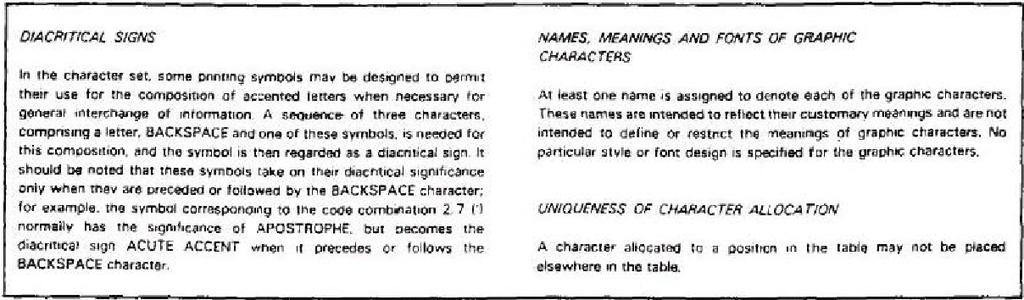
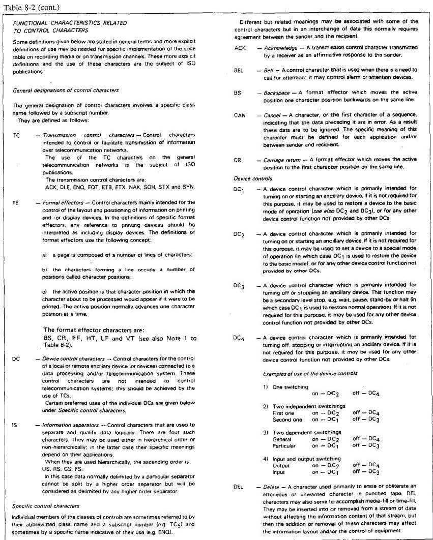
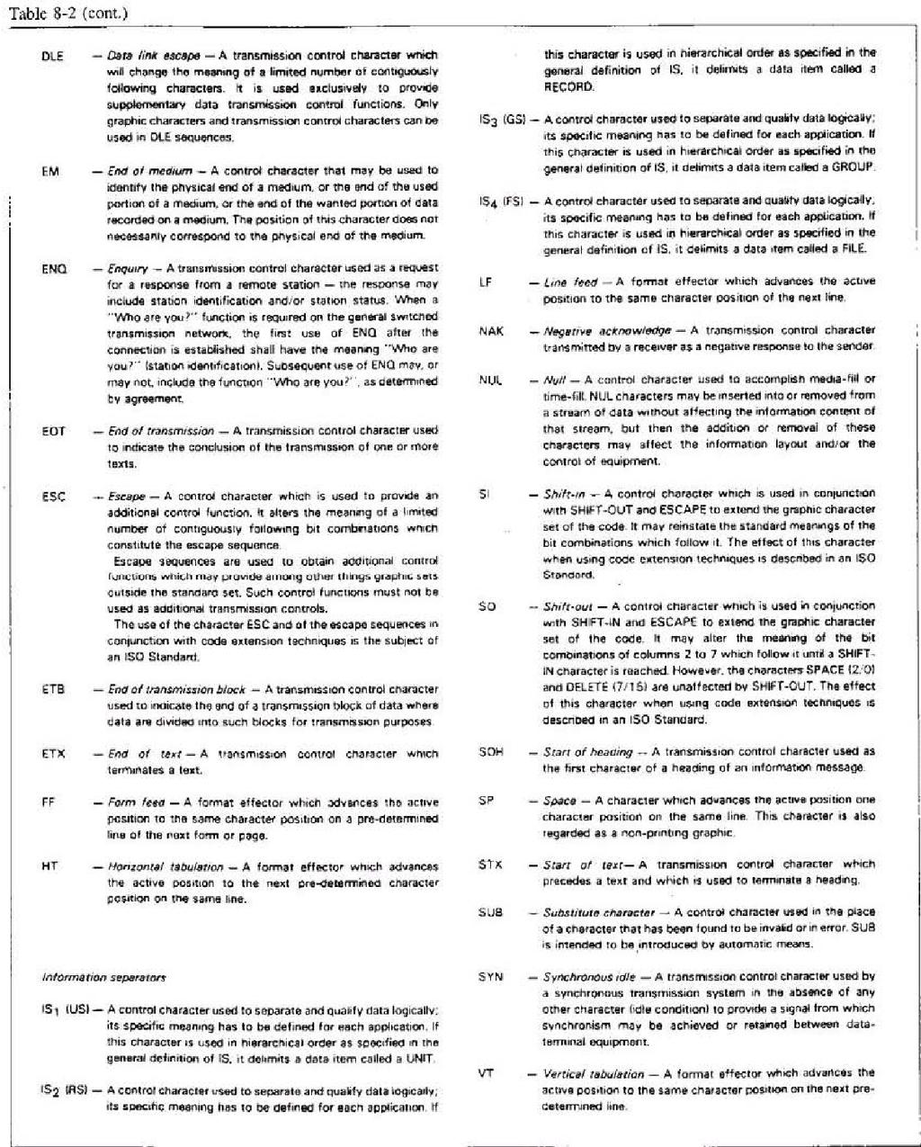
7 The over-all distortion in transmitting equipment used on teletypewriter channels shall not exceed 5 per cent AFTN circuits shall be equipped with a system of continuous check of channel condition. Additionally, controlled circuit protocols shall be applied. 8.3 Intentionally left blank 8.4 Characteristics Of Interregional AFS Circuits Interregional AFS circuits being implemented or upgraded shall employ high quality telecommunications service. Modulation rate shall take into account traffic volumes expected under both normal and alternate route conditions. 8.5 Technical Provisions Relating To ATS Message Transmission Interconnection by direct oromnibus channels low modulation rates - 5- unit code AFTN techniques (cf. 8.2 above) shall be used. 8.6 Technical Provisions Relating To International Ground-Ground Data Interchange At Medium And Higher Signalling Rates General In international data interchange of characters, a 7-unit coded character set providing a repertoire of 128 characters and designated as International Alphabet No. 5 (IA -5) shall be used. Compatibility with the 5-unit coded character set of International Telegraph Alphabet No. 2 (ITA-2) shall be ensured where applicable When the provisions of above are applied, International Alphabet No. 5 (IA -5) contained in Table 8-2 shall be used The serial transmission of units comprising an individual character of IA-5 shall be with the low order unit (b1) transmitted first When IA -5 is used, each character shall include an additional unit for parity in the eighth level position When the provisions of above are applied, the sense of the character parity bit shall produce even parity in links which operate on the start-stop principle, and odd parity in links using end-to-end synchronous operations Character-for-character conversion shall be as listed in Tables 8-3 and 8-4 for all characters which are authorized in the AFTN format for transmission on the AFS in both IA -5 and ITA-2. 7

8 Characters which appear in only one code set, or which are not authorized for transmission on the AFS shall be as depicted in the code conversion tables. 8
9 9
10 10
11 11
12 12
13 8.6.2 Data transmission characteristics The data signalling rate should be chosen from among the following: 600 bits/s bits/s bits/s bits/s bits/s 13
14 The type of transmission for each data signalling rate should be chosen as follows: Data signalling rate Type of transmission 600 bits/s Synchronous or asynchronous serial transmission bits/s Synchronous or asynchronous serial transmission bits/s Synchronous serial transmission bits/s Synchronous serial transmission bits/s Synchronous serial transmission The type of modulation for each data signalling rate should be chosen as follows: Data signalling rate Type of modulation 600 bits/s Frequency bits/s Frequency bits/s Phase bits/s Phase bits/s Phase-amplitude Character Structure On Data Links Intentionally left blank Characters of less than eight bits in length shall be padded out to eight bits in length before transmission over any octet based or bit-oriented communications network. The padding bits shall occupy the higher order end of the octet, i.e. bit 8, bit 7 as required, and shall have the binary values Intentionally left blank Intentionally left blank Ground-ground character-oriented data link control procedures Descriptions. The following descriptions shall apply to data link applications: a) A master station is that station which has control of the data link at a given 14
15 instant. b) A slave station is one that has been selected to receive a transmission from the master station. c) A control station is the single station on a multipoint link that is permitted to assume master status and deliver messages to one or more individually selected (non-control) tributary stations, or it is permitted to assign temporary master status to any of the other tributary stations Message Composition a) A transmission shall consist of characters from IA -5 transmitted in accordance with above and shall be either an information message or a supervisory sequence. b) An information message used for the exchange of data shall take one of the following forms: c) A supervisory sequence shall be composed of either a single transmission control character (EOT, ENQ, ACK, or NAK) or a single transmission control (ENQ) preceded by a prefix of up to 15 non- control characters, or the character DLE used in conjunction with other graphic and control characters to provide additional communication control functions Three system categories are specified in terms of their respective circuit characteristics, terminal configurations, and message transfer procedures as follows: 15
16 System category A: two-way alternate, multipoint allowing either centralized or noncentralized operation and single or multiple message-oriented information transfers without replies (but with delivery verification). System category B: two-way simultaneous, point-to-point employing message associated blocking and modulo 8 numbering of blocks and acknowledgements. System category C: two-way alternate, multipoint allowing only centralized (computer-to-terminal) operation, single or multiple message transfers with replies In addition to the characteristics prescribed in the paragraphs that follow for both system categories A and B, other parameters that shall be accounted for in order to ensure viable, operationally reliable communications include: a) the number of SYN characters required to establish and maintain synchronization; Note: Normally the transmitting station sends three contiguous SYN characters and the receiving station detects atleast two before any action is taken. b) the values of system time-outs for such functions as idle line and no response as well as the number of automatic retries that are to be attempted before manual intervention is signalled; c) the composition of prefixes within a 15 character maximum For multipoint implementations designed to permit only centralized (computer-to-terminal) operations, the provisions of should be employed Block Check Character Both system category A and B shall utilize a block check character to determine the validity of a transmission The block check character shall be composed of 7 bits plus a parity bit Each of the first 7 bits of the block check character shall be the module 2 binary sum of every element in the same bit 1 to bit 7 column of the successive characters of the transmitted block The longitudinal parity of each column of the block, including the block check character, shall be even The sense of the parity bit of the block check character shall be the same as for the information characters (see above) Summation 16
17 The summation to obtain the block check character shall be started by the first appearance of either SOH (start of heading) or STX (start of text) The starting character shall not be included in the summation If an STX character appears after the summation has been started by SOH, then the STX character shall be included in the summation as if it were a text character With the exception of SYN (synchronous idle), all the characters which are transmitted after the zstart of block checks summation shall be included in the summation, including ETB (end of transmission / block) or ETX (end of text) control characters which signals that the following characters is the block check character No character, SYN or otherwise, shall be inserted between the ETB or ETX character and the block check character Description of system category A. System category A is one in which a number of stations are connected by a multipoint link and one station is permanently designated as the control station which monitors the link at all times to ensure orderly operation Link Establishment Procedure To establish the link for transmission, the control station shall either: a) poll one of the tributary stations to assign it master status; or b) assume master status and select one or more tributary (slave) stations to receive a transmission Polling shall be accomplished by the control station sending a polling supervisory sequence consisting of a prefix identifying a single tributary station and ending in ENQ A tributary station detecting its assigned polling supervisory sequence shall assume master status and respond in one of two ways: a) if the station has a message to send, it shall initiate a selection supervisory sequence as described in below; b) if the station has no message to send, it shall send EOT, and master status shall revert to the control station If the control station detects an invalid or no response resulting from a 17
18 poll, it shall terminate by sending EOT prior to resuming polling or selection Selection shall be accomplished by the designated master station sending a selection supervisory sequence consisting of a prefix identifying a single station and ending in ENQ A station detecting its assigned selection supervisory sequence shall assume slave status and send one of two replies: a) if the station is ready to receive, it shall send a prefix followed by ACK. Upon detecting this reply, the master station shall either select another station or proceed with message transfer; b) if the station is not ready to receive, it shall send a prefix followed by NAK and thereby relinquish slave status. If the master station receives NAK, or no reply, it shall either select another or the same tributary station or terminate; c) it shall be permissible for N retries (N _ 0) to be made to select a station for which NAK, an invalid reply, or no response has been received If one or more stations have been selected and have properly responded with ACK, the master station shall proceed with message transfer Message Transfer Procedure The master station shall send a message or series of messages, with or without headings to the selected slave station(s) The transmission of a message shall: a) begin with: - SOH if the message has a heading, - STX if the message has no heading; b) be continuous, ending with ETX, immediately followed by a block check character (BCC) After transmitting one or more messages, the master station shall verify successful delivery at each selected slave station. 18
19 Delivery Verification Procedure The master station shall send a delivery verification supervisory sequence consisting of a prefix identifying a single slave station and ending in ENQ A slave station detecting its assigned delivery verification supervisory sequence shall send one of two replies: a) if the slave station properly received all of the transmission, it shall send an optional prefix followed by ACK; b) if the slave station did not receive all of the transmission properly, it shall send an optional prefix followed by NAK If the master station receives no reply or an invalid reply, it shall request a reply from the same or another slave station until all selected stations have been properly accounted for If the master station receives a negative reply (NAK) or, after N 0 repeat attempts, no reply, it shall repeat that transmission to the appropriate slave stations at a later opportunity After all messages have been sent and delivery verified, the master station shall proceed with link termination Link Termination Procedure The terminate function, negating the master or slave status of all stations and returning master status to the control station, shall be accomplished by the master station transmitting EOT Description of system category B. System category B is one in which two stations are on a point-to-point, full-duplex link and each station has the capability to maintain concurrent master and slave status, i.e. master status on its transmit side and slave status on its receive side and both stations can transmit simultaneously Link Establishment Procedure To establish the link for message transfers (from the calling to the called station), the calling station shall request the identity of the called station by sending an identification supervisory sequence consisting of a DLE character followed by a colon character, an optional prefix, and ENQ The called station, upon detecting ENQ, shall send one of two replies: a) if ready to receive, it shall send a sequence consisting of a DLE 19
20 followed by a colon, a prefix which includes its identity and ended by ACK0 (see below). This establishes the link for message transfers from the calling to the called station; b) if not ready to receive, it shall send the above sequence with the ACK0 replaced by NAK Establishment of the link for message transfers in the opposite direction can be initiated at any time following circuit connection in a similar manner to that described above Message Transfer Procedure System category B message transfer provides for message associated blocking with longitudinal checking and modulo 8 numbered acknowledgements It is permissible for a transmission block to be a complete message or a portion of a message. The sending station shall initiate the transmission with SOTB N followed by: a) SOH if it is the beginning of a message that contains a heading; b) STX if it is the beginning of a message that has no heading; c) SOH if it is an intermediate block that continues a heading; d) STX if it is an intermediate block that continues a text A block which ends at an intermediate point within a message shall be ended with ETB; a block which ends at the end of a message shall be ended with ETX It shall be permissible for each station to initiate and continue to send messages to the other concurrently according to the following sequence. a) It shall be permissible for the sending station (master side) to send blocks, containing messages or parts of messages, continuously to the receiving station (slave side) without waiting for a reply. b) It shall be permissible for replies, in the form of slave responses, to be transmitted by the receiving station while the sending station is sending subsequent blocks. c) If a negative reply is received, the sending station (master side) shall start retransmission with the block following the last block for which the proper affirmative acknowledgement was received Slave responses shall be according to one of the following: a) if a transmission block is received without error and the station is ready to 20
21 receive another block, it shall send DLE, a colon, an optional prefix, and the appropriate acknowledgement ACKN (referring to the received block beginning with SOTB N, e.g. ACK0, transmitted as DLE0 is used as the affirmative reply to the block numbered SOTB0, DLE1 for SOTB1, etc.); b) if a transmission block is not acceptable, the receiving station shall send DLE, a colon, an optional prefix, and NAK Slave responses should be interleaved between message blocks and transmitted at the earliest possible time Link Termination Procedure If the link has been established for message transfers in either or both directions, the sending of EOT by a station shall signal the end of message transfers in that direction. To resume message transfers after sending EOT, the link shall be re-established in that direction EOT shall only be transmitted by a station after all outstanding slave responses have been received or otherwise accounted for Circuit Disconnection On switched connections, the data links in both directions shall be terminated before the connection is cleared. In addition, the station initiating clearing of the connection shall first announce its intention to do so by transmitting the twocharacter sequence DLE EOT, followed by any other signals required to clear the connection Description of system category C (centralized). System category C (centralized) is one (like system category A) in which a number of stations are connected by a multipoint link and one station is designated as the control station but (unlike system category A) provides only for centralized (computer-toterminal) operations where message interchange (with replies) shall be constrained to occur only between the control and a selected tributary station Link Establishment Procedure To establish the link for transmission the control station shall either: a) poll one of the tributary stations to assign it master status; or b) assume master status and select a tributary station to assume slave status and receive a transmission according to either of two prescribed selection procedures: 1) selection with response (see below); or 21
22 2) fast select (see below) Polling is accomplished by the control station sending a polling supervisory sequence consisting of a prefix identifying a single tributary station and ending in ENQ A tributary station detecting its assigned polling supervisory sequence shall assume master status and respond in one of two ways: a) if the station has a message to send, it shall initiate message transfer. The control station assumes slave status; b) if the station has no message to send, it shall send EOT and master status shall revert to the control station If the control station detects an invalid or no response resulting from a poll, it shall terminate by sending EOT prior to resuming polling or selection Selection with response is accomplished by the control station assuming master status and sending a selection supervisory sequence consisting of a prefix identifying a single tributary station and ending in ENQ A tributary station detecting its assigned selection supervisory sequence shall assume slave status and send one of two replies: a) if the station is ready to receive, it shall send an optional prefix followed by ACK. Upon detecting this reply, the master station shall proceed with message transfer; b) if the station is not ready to receive, it shall send an optional prefix followed by NAK. Upon detecting NAK, it shall be permissible for the master station to again attempt selecting the same tributary station or initiate termination by sending EOT Fast select is accomplished by the control station assuming master status and sending a selection supervisory sequence, and without ending this transmission with ENQ or waiting for the selected tributary to respond, proceeding directly to message transfer Message Transfer Procedure The station with master status shall send a single message to the station with slave status and wait for a reply The message transmission shall: a) begin with: - SOH if the message has a heading, 22
23 - STX if the message has no heading; and b) be continuous, ending with ETX, immediately followed by BCC The slave station, upon detecting ETX followed by BCC, shall send one of two replies: a) if the messages were accepted and the slave station is ready to receive another message, it shall send an optional prefix followed by ACK. Upon detecting ACK, the master station shall be permitted either to transmit the next message or initiate termination; b) if the message was not accepted and the slave station is ready to receive another message, it shall send an optional prefix followed by NAK. Upon detecting NAK, the master station may either transmit another message or initiate termination. Following the NAK reply, the next message transmitted need not be a retransmission of the message that was not accepted If the master station receives an invalid or no reply to a message, it shall be permitted to send a delivery verification supervisory sequence consisting of an optional prefix followed by ENQ. Upon receipt of a delivery verification supervisory sequence, the slave station repeats its last reply N retries (N 0) may be made by the master station in order to get a valid slave reply. If a valid reply is not received after N retries, the master station exits to a recovery procedure Link Termination Procedure The station with master status shall transmit EOT to indicate that it has no more messages to transmit. EOT shall negate the master/slave status of both stations and return master status to the control station Ground-ground bit-oriented data link control procedures The following descriptions shall apply to data link applications contained in this section: a) Bit-oriented data link control procedures enable transparent transmission that is independent of any encoding. b) A data link is the logical association of two interconnected stations, including the communication control capability of the interconnected 23
24 stations. c) A station is a configuration of logical elements, from or to which messages are transmitted on a data link, including those elements which control the message flow on the link via communication control procedures. d) A combined station sends and receives both commands and responses and is responsible for control of the data link. e) Data communication control procedures are the means used to control and protect the orderly interchange of information between stations on a data link. f) A component is defined as a number of bits in a prescribed order within a sequence for the control and supervision of the data link. g) An octet is a group of 8 consecutive bits. h) A sequence is one or more components in prescribed order comprising an integral number of octets. i) A field is a series of a specified number of bits or specified maximum number of bits which performs the functions of data link or communications control or constitutes data to be transferred. j) A frame is a unit of data to be transferred over the data link, comprising one or more fields in a prescribed order Bit-Oriented Data Link Control Procedures For Point-To-Point, Ground-Ground Data Interchange Applications Employing Synchronous Transmission Facilities Frame format. Frames shall contain not less than 32 bits, excluding the opening and closing flags, and shall conform to the following format: A frame shall consist of an opening flag (F), an address field (A), a control field (C), an optional information field (I), a frame check sequence (FCS), and a closing flag sequence (F), and shall be transmitted in that order The flag (F) shall be the 8-bit sequence which delimits the 24
25 beginning and ending of each frame. It shall be permissible for the closing flag of a frame to also serve as the opening flag of the next frame The address (A) field shall consist of one octet, excluding 0 bits added to achieve transparent transmission, which shall contain the link address of the combined station The control (C) field shall consist of one octet, excluding 0 bits added to achieve transparent transmission, and shall contain the commands, responses, and frame sequence number components for the control of the data link The information (I) field shall contain digital data which may be presented in any code or sequence but shall not exceed a maximum of 259 octets, excluding 0 bits added to achieve transparent transmission. The I field shall always be a multiple of 8 bits in length The frame check sequence (FCS) shall consist of two octets, excluding 0 bits added to achieve transparent transmission, and shall contain the error detecting bits A frame check sequence (FCS) shall be included in each frame for the purpose of error checking The error checking algorithm shall be a cyclic redundancy check (CRC) The CRC polynomial (P(x)) shall be The FCS shall be a 16-bit sequence. This FCS shall be the ones complement of the remainder, R(x), obtained from the modulo 2 division of by the CRC polynomial, P(x). G(x) shall be the contents of the frame existing between, but including neither, the final bit of the opening flag nor the first bit of the FCS, excluding bits inserted for transparent transmission. K shall be the length of G(x) (number of bits) The generation and checking of the FCS accumulation shall be as follows: a) the transmitting station shall initiate the FCS accumulation with the first (least significant) bit of the address (A) field and shall include all bits up to and including the last bit preceding the FCS sequence, but shall exclude all 0 bits (if any) inserted to achieve transparent transmission; 25
 the receiving station shall carry out the cyclic redundancy check (CRC) on the content of the frame commencing with the first bit received following the opening flag, and shall include all bits up")
26 b) upon completion of the accumulation the FCS shall be transmitted, starting with bit b1 (highest order coefficient) and proceeding in sequence to bit b16 (lowest order coefficient) as shown below; c) the receiving station shall carry out the cyclic redundancy check (CRC) on the content of the frame commencing with the first bit received following the opening flag, and shall include all bits up to and including the last bit preceding the closing flag, but shall exclude all 0 bits (if any) deleted according to the rules for achievement of transparency; d) upon completion of the FCS accumulation, the receivingstation shall examine the remainder. In the absence of transmission error, the remainder shall be (x0 through x15, respectively). Achievement of transparency. The frame format contents (A, C, link data field, and FCS) shall be capable of containing any bit configuration. The following rules shall apply to all frame contents, except flag sequences: a) the transmitting station shall examine the frame contents before transmission, and shall insert a single 0 bit immediately following each sequence of 5 consecutive 1 bits; b) the receiving station shall examine the received frame contents for patterns consisting of 5 consecutive 1 bits immediately followed by one (or more) 0 bit(s) and shall remove the 0 bit which directly follows 5 consecutive 1 bits Special transmission sequences and related link states. In addition to employing the prescribed repertoire of commands and responses to manage the interchange of data and control information, stations shall use the following conventions to signal the indicated conditions: a) Abort is the procedure by which a station in the process of sending a frame ends the frame in an unusual manner such that the receiving station shall ignore the frame. The conventions for aborting a frame shall be: 26
27 1) transmitting at least seven, but less than fifteen, one bits (with no inserted zeros); 2) receiving seven one bits. b) Active link state. A link is in an active state when a station is transmitting a frame, an abort sequence, or interframe time fill. When the link is in the active state, the right of the transmitting station to continue transmission shall be reserved. c) Interframe time fill. Interframe time fill shall be accomplished by transmitting continuous flags between frames. There is no provision for time fill within a frame. d) Idle link state. A link is in an idle state when a continuous one condition is detected that persists for 15 bit times, or longer. Idle link time fill shall be a continuous one condition on the link. e) Invalid frame. An invalid frame is one that is not properly bounded by two flags or one which is shorter than 32 bits between flags Modes Operational mode. The operational mode shall be the asynchronous balanced mode (ABM) It shall be permissible for a combined station in ABM to transmit without invitation from the associated station A combined station in ABM shall be permitted to transmit any command or response type frame except DM Non-operational mode. The non-operational mode shall be the asynchronous disconnected mode (ADM) in which a combined station is logically disconnected from the data link It shall be permissible for a combined station in ADM to transmit without invitation from the associated station A combined station in ADM shall transmit only SABM, DISC, UA and DM frames. (See below for a description of the commands and responses to which these frame types refer.) A combined station in ADM shall transmit a DM when a DISC is received, and shall discard all other received command frames except SABM. If a discarded command frame has the P bit set to 1, the combined station shall transmit a DM with the F bit set to Control field functions and parameters. Control fields contain a 27
28 command or a response and sequence numbers where applicable. Three types of control fields shall be used to perform: a) numbered information transfer (I-frames); b) numbered supervisory functions (S-frames); and c) unnumbered control functions (U-frames). The control field formats shall be as shown in Table 8-5. The functional frame designation associated with each type control field as well as the control field parameters employed in performing these functions shall be described in the following paragraphs The I-frame type is used to perform information transfers. Except for some special cases it is the only format which shall be permitted to contain an information field The S-frame type is used for supervisory commands and responses that perform link supervisory control functions such as acknowledge information frames, request transmission or retransmission of information frames, and to request a temporary suspension of transmission of I-frames. No information field shall be contained in the S-frame The U-frame type is used for unnumbered commands and responses that provide additional link control functions. One of the U-frame responses, the frame reject (FRMR) response, shall contain an information field; all other frames of the U-frame type shall not contain an information field The station parameters associated with the three control field types shall be as follows: a) Modulus. Each I-frame shall be sequentially numbered with a send sequence count, N(S), having value 0 through modulus minus one (where modulus is the modulus of the sequence numbers). 28
29 The modulus shall be 8. The maximum number of sequentially numbered I- frames that a station shall have outstanding (i.e. unacknowledged) at any given time shall never exceed one less than the modulus of the sequence numbers. This restriction on the number of outstanding frames is to prevent any ambiguity in the association of transmission frames with sequence numbers during normal operation and/or error recovery. b) The send state variable V(S) shall denote the sequence number of the next in-sequence I-frame to be transmitted. 1) The send state variable shall take on the value 0 through modulus minus one (modulus is the modulus of the sequence numbering and the numbers cycle through the entire range). 2) The value of V(S) shall be incremented by one with each successive in-sequence I-frame transmission, but shall not exceed the value of N(R) contained in the last received frame by more than the maximum permissible number of outstanding I frames (k). See i) below for the definition of k. c) Prior to transmission of an in-sequence I-frame, the value of N(S) shall be updated to equal the value of V(S). d) The receive state variable V(R) shall denote the sequence number of the next in-sequence I-frame to be received. 1) V(R) shall take on the values 0 through modulus minus one. 2) The value of V(R) shall be incremented by one after the receipt of an error-free, in-sequence I-frame whose send sequence number N(S), equals V(R). e) All I-frames and S-frames shall contain N(R), the expected sequence number of the next received frame. Prior to transmission of either an I or an S type frame, the value of N(R) shall be updated to equal the current value of the receive state variable. N(R) indicates that the station transmitting the N(R) has correctly received all I-frames numbered up to and including N(R) - 1. f) Each station shall maintain an independent send state variable, V(S), and receive state variable, V(R), on the I-frames it sends and receives. That is, each combined station shall maintain a V(S) count on the I - frames it transmits and a V(R) count on the received from the remote combined station. -Iframes it has correctly g) The poll (P/F) bit shall be used by a combined station to solicit (poll) a response or sequence of responses from the remote combined station. 29
30 h) The final (P/F) bit shall be used by the remote combined station to indicate the response frame transmitted as the result of a soliciting (poll) command. i) The maximum number (k) of sequentially numbered I-frames that a station may have outstanding (i.e. unacknowledged) at any given time is a station parameter which shall never exceed the modulus Commands and responses. It shall be permissible for a combined station to generate either commands or responses. A command shall contain the remote station address while a response shall contain the sending station address. The mnemonics associated with all of the commands and responses prescribed for each of the three frame types (I, S, and U) and the corresponding encoding of the control field are as shown in Table The I-frame command provides the means for transmitting sequentially numbered frames, each of which shall be permitted to contain an information field The S-frame commands and responses shall be used to perform numbered supervisory functions (such as acknowledgement, polling, temporary suspension of information transfer, or error recovery) The receive ready command or response (RR) shall be used by a station to: a) indicate that it is ready to receive an I-frame; b) acknowledge previously received I-frames numbered up to and including N(R) - 1; 30
31 c) clear a busy condition that was initiated by the transmission of RNR It shall be permissible to issue a reject command or response (REJ) to request retransmission of frames starting with the I-frame numbered N(R) where: a) I-frames numbered N(R) - 1 and below are acknowl-edged; b) additional I-frames pending initial transmission are to be transmitted following the retransmitted I-frame(s); c) only one REJ exception condition, from one given station to another station, shall be established at any given time: another REJ shall not be issued until the first REJ exception condition has been cleared; d) the REJ exception condition is cleared (reset) upon the receipt of an I- frame with an N(S) count equal to the N(R) of the REJ command/ response The receive not ready command or response (RNR) shall be used to indicate a busy condition, i.e. temporary inability to accept additional incoming I frames, where: a) frames numbered up to and including N(R) - 1 are acknowledged; b) frame N(R) and any subsequent I-frames received, if any, are not acknowledged (the acceptance status of these frames shall be indicated in subsequent exchanges); c) the clearing of a busy condition shall be indicated by the transmission of an RR, REJ, SABM, or UA with or without the P/F bit set to a) A station receiving an RNR frame when in the process of transmitting should stop transmitting I-frames at the earliest possible time. b) Any REJ command or response which was received prior to the RNR should be actioned before the termination of transmission. c) It should be permissible for a combined station to use the RNR command with the poll bit set to 1 to obtain a supervisory frame with the final bit set to 1 from the remote combined station. 31
32 It shall be permissible for the selective reject command or response -Iframe (SREJ) to be used to request retransmission of the single numbered N(R) where: a) frames numbered up to N(R) - 1 are acknowledged; frame N(R) is not accepted; the only I-frames accepted are those received correctly and in sequence following the I-frame requested; the specific I-frame to be retransmitted is indicated by the N(R) in the SREJ command/response; b) the SREJ exception condition is cleared (reset) upon receipt of an I- frame with an N(S) count equal to the N(R) of the SREJ; c) after a station transmits a SREJ it is not permitted to transmit SREJ or REJ for an additional sequence error until the first SREJ error condition has been cleared; d) I-frames that have been permitted to be transmitted following the I- frame indicated by the SREJ are not retransmitted as the result of receiving a SREJ; and e) it is permissible for additional I-frames pending initial transmission to be transmitted following the retransmission of the specific I-frame requested by the SREJ The U-frame commands and responses shall be used to extend the number of link control functions. Transmitted U-frames do not increment the sequence counts at either the transmitting or receiving station. a) The U-frame mode-setting commands (SABM, and DISC) shall be used to place the addressed station in the appropriate response mode (ABM or ADM) where: 1) upon acceptance of the command, the station send and receive state variables, V(S) and V(R), are set to zero; 2) the addressed station confirms acceptance at the earliest possible time by transmission of a single unnumbered acknowledgement, UA; 3) previously transmitted frames that are unacknowl-edged when the command is actioned remain unacknowledged; 4) the DISC command is used to perform a logical disconnect, i.e. to inform the addressed combined station that the transmitting combined station is suspending operation. No information field shall be permitted with the DISC command. 32
33 b) The unnumbered acknowledge response (UA) shall be used by a combined station to acknowledge the receipt and acceptance of an unnumbered command. Received unnumbered commands are not actioned until the UA response is transmitted. No information field shall be permitted with the UA response. c) The frame reject response (FRMR), employing the information field described below, shall be used by a combined station in the operational mode (ABM) to report that one of the following conditions resulted from the receipt of a frame without an FCS error: 1) a command/response that is invalid or not implemented; 2) a frame with an information field that exceeds the size of the buffer available; 3) a frame having an invalid N(R) count. Note.- An invalid N(R) is a count which points to an -Iframe which has previously been transmitted and acknowledged or to an I-frame which has not been transmitted and is not the next sequential I-frame pending transmission d) The disconnected mode response (DM) shall be used to report a nonoperational status where the station is logically disconnected from the link. No information field shall be permitted with the DM response Exception condition reporting and recovery. This section specifies the procedures that shall be employed to effect recovery following the detection or occurrence of an exception condition at the link level. Exception conditions described are those situations that may occur as the result of transmission errors, station malfunction, or operational situations Busy condition. A busy condition occurs when a station temporarily cannot receive or continue to receive I-frames due to internal constraints, e.g. due to buffering limitations. The busy condition shall be reported to the remote combined station by the transmission of an RNR frame with the N(R) number of the next I frame that is expected. It shall be permissible for traffic pending transmission at the busy station to be transmitted prior to or following the RNR Upon receipt of an RNR, a combined station in ABM shall cease transmitting I-frames at the earliest possible time by completing or aborting the frame in process. The combined station receiving an RNR shall perform a time-out operation before resuming asynchronous transmission of I-frames unless the busy condition is reported as cleared by the remote combined station. If the RNR was received as a command with the P bit set to 1, the receiving station shall respond with an S-frame with the F bit set to The busy condition shall be cleared at the station which transmitted the 33
34 RNR when the internal constraint ceases. Clearance of the busy condition shall be reported to the remote station by transmission of an RR, REJ, SABM, or UA frame (with or without the P/F bit set to 1 ) N(S) sequence error. An N(S) sequence exception shall be established in the receiving station when an FCS error) contains an N(S) sequence number that is not equal to the receive variable V(R) at the receiving station. The receiving station shall not acknowledge (shall not increment its receive variable V(R)) the frame causing the sequence error, or any -Iframes which may follow, until an -Iframe with the correct N(S) number is received. A station that receives one or more I-frames having sequence errors, but which are otherwise error free, shall accept the control information contained in the N(R) field and the P/F bit to perform link control functions, e.g. to receive acknowledgement of previously transmitted I-frames (via the N(R)), to cause the station to respond (P bit set to 1 ) The means specified in and below shall be available for initiating the retransmission of lost or errored I-frames following the occurrence of a sequence error Where the REJ command/response is used to initiate an exception recovery following the detection of a sequence error, only one sent REJ exception condition, from one station to another station, shall be established at a time. A sent REJ exception shall be cleared when the requested I-frame is received. A station receiving REJ shall initiate sequential (re)transmission of I-frames starting with the I- frame indicated by the N(R) contained in the REJ frame In the event a receiving station, due to a transmission error, does not receive (or receives and discards) a single I-frame or the last I-frame(s) in a sequence of I-frames, it shall not detect an out-of-sequence exception and, therefore, shall not transmit REJ. The station which transmitted the unacknowledged I-frame(s) shall, following the completion of a system-specified time-out period, take appropriate recovery action to determine the sequence number at which retransmission must begin A combined station which has timed out waiting for a response should not retransmit all unacknowledged frames immediately. The station may enquire about status with a supervisory frame FCS error. Any frame with an FCS error shall not be accepted by the receiving station and will be discarded. No action shall be taken by the receiving station as the result of that frame Frame reject exception condition. A frame reject exception condition shall be established upon the receipt of an error-free frame which contains an invalid or unimplemented control field, an invalid N(R), or an information field which has exceeded the maximum established storage capability. If a frame reject exception condition occurs in a combined station, the station shall either: a) take recovery action without reporting the condition to the remote combined station; or 34
35 b) report the condition to the remote combined station with a FRMR response. The remote station will then be expected to take recovery action; if, after waiting an appropriate time, no recovery action appears to have been taken, the combined station reporting the frame reject exception condition may take recovery action. Recovery action for balanced operation includes the transmission of an implemented mode-setting command. Higher level functions may also be involved in the recovery Mode-setting contention. A mode-setting contention situation exists when a combined station issues a mode-setting command and, before receiving an appropriate response (UA or DM), receives a mode-setting command from the remote combined station. Contention situations shall be resolved in the following manner: a) when the send and receive mode-setting commands are the same, each combined station shall send a UA response at the earliest respond opportunity. Each combined station shall either enter the indicated mode immediately or defer entering the indicated mode until receiving a UA response. In the latter case, if the UA response is not received: 1) the mode may be entered when the response timer expires; or 2) the mode-setting command may be reissued; b) when the mode-setting commands are different, each combined station shall enter ADM and issue a DM response at the earliest respond opportunity. In the case of DISC contention with a different mode-setting command, no further action is required Time-out functions. Time-out functions shall be used to detect that a required or expected acknowledging action or response to a previously transmitted frame has not been received. Expiration of the time-out function shall initiate appropriate action, e.g. error recovery or reissuance of the P bit. The duration of the following time-out functions is system dependent and subject to bilateral agreement: a) combined stations shall provide a time-out function to determine that a response frame with F bit set to 1 toa command frame with the P bit set to 1 has not been received. The time-out function shall automatically cease upon receipt of a valid frame with the F bit set to 1 ; b) a combined station which has no P bit outstanding, andwhich has transmitted one or more frames for which responses are anticipated shall start a time-out 35
36 function to detect the no-response condition. The time-out function shall cease when an I- or S-frame is received with the N(R) higher than the last received N(R) (actually acknowledging one or more I-frames) Intentionally left blank 9. AIRCRAFT ADDRESSING SYSTEM 9.1 The aircraft address shall be twenty-four-bit aircraft address allocated by ICAO to India and assigned in accordance with CAR Section 2 Series R Part IV Non-aircraft transponders that are installed on aerodrome surface vehicles, obstacles or fixed Mode S target detection devices for surveillance and/ or radar monitoring purposes shall be assigned 24-bit aircraft addresses. The 24-bit aircraft address for non-aircraft transponders may be obtained from DGCA (Attn. Director of Airworthiness, O/o DGCA, Opp. Safdarjung Airport, New Delhi ). Note 1. Under such specific conditions, the term aircraft can be understood as aircraft (or pseudo-aircraft) or vehicle (A/V) where a limited set of data is generally sufficient for operational purposes. Note 2. Each non-aircraft transponder used on aerodrome surface vehicle shall have a unique address Mode S transponders used under specific conditions stated in should not have any negative impact on the performance of existing ATS surveillance systems and ACAS. SECTION II - VOICE COMMUNICATION SYSTEM 1. Definitions Note : Material on secondary power supply and guidance material concerning reliability and availability for communications systems is contained in CAR SECTION-9, Series D Part II, para Aeronautical Mobile Service 2.1 Air-Ground VHF Communication System Characteristics The characteristics of the air-ground VHF communication system used in the International Aeronautical Mobile Service shall be in conformity with the following specifications: Radiotelephone emissions shall be double sideband (DSB) amplitude modulated (AM) carriers. The designation of emission is A3E, as specified in the ITU Radio Regulations Spurious emissions shall be kept at the lowest value which the state of 36
37 technique and the nature of the service permit The radio frequencies used shall be selected from the radio frequencies in the band MHz. The separation between assignable frequencies (channel spacing) and frequency tolerances applicable to elements of the system shall be as specified in CAR SECTION-9 Series D Part VI The design polarization of emissions shall be vertical. 2.2 System Characteristics Of The Ground Installation Transmitting function Frequency stability. The radio frequency of operation shall not vary more than plus or minus per cent from the assigned frequency. Where 25 khz channel spacing is introduced, the radio frequency of operation shall not vary more than plus or minus per cent from the assigned frequency. Where 8.33 khz channel spacing is introduced, the radio frequency of operation shall not vary more than plus or minus per cent from the assigned frequency Offset carrier systems in 25 khz, 50 khz and 100 khz channel spaced environments. The stability of individual carriers of an offset carrier system shall be such as to prevent first-order heterodyne frequencies of less than 4 khz and, additionally, the maximum frequency excursion of the outer carrier frequencies from the assigned carrier frequency shall not exceed 8 khz. Offset carrier systems shall not be used on 8.33 khz spaced channels Power: On a high percentage of occasions, the effective radiated power should be such as to provide a field strength of a least 75 microvolts per metre (minus 109 dbw/m2) within the defined operational coverage of the facility, on the basis of free space propagation Modulation. A peak modulation factor of at least 0.85 shall be achievable Means should be provided to maintain the average modulation factor at the highest practicable value without overmodulation Receiving function Frequency stability. Where 8.33 khz channel spacing is introduced in accordance with CAR SECTION-9 Series D Part VI, the radio frequency of operation shall not vary more than plus or minus per cent from the assigned frequency Sensitivity. After due allowance has been made for feeder loss and antenna polar diagram variation, the sensitivity of the receiving function shall be such as to provide on a high percentage of occasions an audio output signal with a wanted/unwanted ratio of 15 db, with a 50 per cent amplitude modulated (A3E) radio 37
38 signal having a field strength of 20 microvolts per metre (minus 120 dbw/m2) or more Effective acceptance bandwidth. When tuned to a channel having a width of 25 khz, 50 khz or 100 khz, the receiving system shall provide an adequate and intelligible audio output when the signal specified at above has a carrier frequency within plus or minus per cent of the assigned frequency. When tuned to a channel having a width of 8.33 khz, the receiving system shall provide an adequate and intelligible audio output when the signal specified at above has a carrier frequency within plus or minus per cent of the assigned frequency Adjacent channel rejection. The receiving system shall ensure an effective rejection of 60 db or more at the next assignable channel. 2.3 System Characteristics Of The Airborne Installation Transmitting function Frequency stability. The radio frequency of operation shall not vary more than plus or minus per cent from the assigned frequency. Where 25 khz channel spacing is introduced, the radio frequency of operation shall not vary more than plus or minus per cent from the assigned frequency. Where 8.33 khz channel spacing is introduced, the radio frequency of operation shall not vary more than plus or minus per cent from the assigned frequency Power: On a high percentage of occasions, the effective radiated power shall be such as to provide a fieldstrength of at least 20 microvolts per metre (minus 120 dbw/m2) on the basis of free space propagation, at ranges and altitudes appropriate to the operational conditions pertaining to the areas over which the aircraft is operated Adjacent channel power. The amount of power from a 8.33 khz airborne transmitter under all operating conditions when measured over a 7 khz channel bandwidth centred on the first 8.33 khz adjacent channel shall not exceed - 45 db below the transmitter carrier power. The above adjacent channel power shall take into account the typical voice spectrum Modulation. A peak modulation factor of at least 0.85 shall be achievable. Means should be provided to maintain the average modulation factor at the highest practicable value without overmodulation Receiving function Frequency stability. Where 8.33 khz channel spacing is introduced, the radio frequency of operation shall not vary more than plus or minus per cent from the assigned frequency Sensitivity After due allowance has been made for aircraft feeder mismatch, attenuation loss 38
39 and antenna polar diagram variation, the sensitivity of the receiving function should be such as to provide on a high percentage of occasions an audio output signal with a wanted/unwanted ratio of 15 db, with a 50 per cent amplitude modulated (A3E) radio signal having a field strength of 75 microvolts per metre (minus 109 dbw/m2) Effective acceptance bandwidth for 100 khz, 50 khz and 25 khz channel spacing receiving installations. When tuned to a channel as having a width of 25 khz, 50 khz or 100 khz, the receiving function shall ensure an effective acceptance bandwidth as follows: a) in areas where offset carrier systems are employed, the receiving function shall provide an adequate audio output when the signal specified at above has a carrier frequency within 8 khz of the assigned frequency; b) in areas where offset carrier systems are not employed, the receiving function shall provide an adequate audio output when the signal specified at above has a carrier frequency of plus or minus per cent of the assigned frequency Effective acceptance bandwidth for 8.33 khz channel spacing receiving installations. When tuned to a channel, as having a width of 8.33 khz, the receiving function shall provide an adequate audio output when the signal specified at above has a carrier frequency within plus or minus per cent of the assigned frequency. Note: The effective acceptance band width includes Dopler shift Adjacent channel rejection. The receiving function shall ensure an effective adjacent channel rejection as follows: a) 8.33 khz channels: 60 db or more at plus or minus 8.33 khz with respect to the assigned frequency, and 40 db or more at plus or minus 6.5 khz; b) 25 khz channel spacing environment: 50 db or more at plus or minus 25 khz with respect to the assigned frequency and 40 db or more at plus or minus 17 khz; c) 50 khz channel spacing environment: 50 db or more at plus or minus 50 khz with respect to the assigned frequency and 40 db or more at plus or minus 35 khz; d) 100 khz channel spacing environment: 50 db or more at plus or minus 100 khz with respect to the assigned frequency Whenever practicable, the receiving system should ensure an effective adjacent channel rejection characteristic of 60 db or more at plus or minus 25 khz, 50 khz and 100 khz from the assigned frequency for receiving systems intended to operate in channel spacing environments of 25 khz, 50 khz and 100 khz 39
40 respectively In the case of receivers complying with above used in areas where offset carrier systems are in force, the characteristics of the receiver should be such that: a) the audio frequency response precludes harmful levels of audio heterodynes resulting from the reception of two or more offset carrier frequencies; b) the receiver muting circuits, if provided, operate satisfactorily in the presence of audio heterodynes resulting from the reception of two or more offset carrier frequencies VDL - Interference Immunity Performance For equipment intended to be used in independent operations of services applying DSB-AM and VDL technology on board the same aircraft, the receiving function shall provide an adequate and intelligible audio output with a desired signal field strength of not more than 150 microvolts per metre (minus 102 dbw/m2) and with an undesired VDL signal field strength of at least 50 db above the desired field strength on any assignable channel 100 khz or more away from the assigned channel of the desired signal, subject to the conditions of Intentionally left blank Intentionally left blank Requirements for mandatory compliance of the provisions of shall be made on the basis of regional air navigation agreements which specify the airspace of operation and the implementation timescales The agreement indicated in shall provide at least two years notice of mandatory compliance of airborne systems Interference immunity performance The VHF communications receiving system shall provide satisfactory performance in the presence of two signal, third-order intermodulation products caused by VHF FM broadcast signals having levels at the receiver input of minus 5 dbm The VHF communications receiving system shall not be desensitized in the presence of VHF FM broadcast signals having levels at the receiver input of minus 5 dbm All installations of airborne VHF communications receiving systems shall meet the provisions of and above. 40
41 Intentionally left blank 2.4 Single Sideband (SSB) HF Communication System Characteristics For Use In The Aeronautical Mobile Service The characteristics of the air-ground HF SSB system, where used in the Aeronautical Mobile Service, shall be in conformity with the following specifications Frequency Range HF SSB installations shall be capable of operation at any SSB carrier (reference) frequency available to the Aeronautical Mobile (R) Service in the band 2.8 MHz to 22 MHz and necessary to meet the approved assignment plan for the region(s) in which the system is intended to operate, and in compliance with the relevant provisions of the Radio Regulations The equipment shall be capable of operating on integral multiples of 1 khz Sideband Selection The sideband transmitted shall be that on the higher frequency side of its carrier (reference) frequency Carrier (Reference) Frequency Channel utilization shall be in conformity with the table of carrier (reference) frequencies at 27/16 and the Allotment Plan at 27/186 to 27/207 inclusive (or frequencies established on the basis of 27/21, as may be appropriate) of International Telecommunication Union (ITU) Appendix S Classes Of Emission And Carrier Suppression The system shall utilize the suppressed carrier class of emission J3E (also J7B and J9B as applicable). When SELCAL is employed as specified in Para 3 of this Part, the installation shall utilize class H2B emission. Class A3E and H3E emission shall be utilised in accordance with below Intentionally left blank Intentionally left blank For stations directly involved in co-ordinated search and rescue operations using the frequencies khz and khz, the class of emission J3E should be used; however, since maritime mobile and land mobile services may be involved, A3E and H3E classes of emission may be used After 1 April 1981 no new DSB equipment shall be installed Aircraft station transmitters shall be capable of at least 26 db carrier 41
42 suppression with respect to peak envelope power (Pp) for classes of emission J3E, J7B or J9B Aeronautical station transmitters shall be capable of 40 db carrier suppression with respect to peak envelope power (Pp) for classes of emission J3E, J7B or J9B Audio Frequency Bandwidth For radiotelephone emissions the audio frequencies shall be limited to between 300 and Hz and the occupied bandwidth of other authorized emissions shall not exceed the upper limit of J3E emissions. In specifying these limits, however, no restriction in their extension shall be implied in so far as emissions other than J3E are concerned, provided that the limits of unwanted emissions are met (see below) For other authorized classes of emission the modulation frequencies shall be such that the required spectrum limits of below will be met Frequency Tolerance The basic frequency stability of the transmitting function for classes of emission J3E, J7B or J9B shall be such that the difference between the actual carrier of the transmission and the carrier (reference) frequency shall not exceed: - 20 Hz for airborne installations; - 10 Hz for ground installations The basic frequency stability of the receiving function shall be such that, with the transmitting function stabilities specified in above, the over-all frequency difference between ground and airborne functions achieved in service and including Doppler shift, does not exceed 45 Hz. However, a greater frequency difference shall be permitted in the case of supersonic aircraft Spectrum Limits For aircraft station transmitter types and for aeronautical station transmitters first installed before 1 February 1983 and using single sideband classes of emission H2B, H3E, J3E, J7B or J9B the mean power of any emission on any discrete frequency shall be less than the mean power (Pm) of the transmitter in accordance with the following: - on any frequency removed by 2 khz or more up to 6 khz from the assigned frequency: at least 25 db; - on any frequency removed by 6 khz or more up to 10 khz from the assigned frequency: at least 35 db; 42
43 - on any frequency removed from the assigned frequency by 10 khz or more: a) aircraft station transmitters: 40 db; b) aeronautical station transmitters: For aircraft station transmitters first installed after 1 February 1983 and for aeronautical station transmitters in use as of 1 February 1983 and using single sideband classes of emission H2B, H3E, J3E, J7B or J9B, the peak envelope power (Pp) of any emission on any discrete frequency shall be less than the peak envelope power (Pp) of the transmitter in accordance with the following: - on any frequency removed by 1.5 KHz or more up to 4.5 KHz from the assigned frequency: at least 30 db; - on any frequency removed by 4.5 KHz or more up to 7.5 KHz from the assigned frequency: at least 38 db; - on any frequency removed from the assigned frequency by 7.5 KHz or more: a) aircraft station transmitters: 43 db; b) aeronautical station transmitters: for transmitter power up to and including 50 W: For transmitter power more than 50 W: 60 db. Note: See Figures 2 1 and
44 44
45 Power Aeronautical station installations. Except as permitted by the relevant provisions of ITU Appendix S27/68 and S27/60 as given below, the peak envelope power (Pp) supplied to the antenna transmission line for H2B, H3E, J3E, J7B or J9B classes of emissions shall not exceed a maximum value of 6 KW Aircraft station installations. The peak envelope power supplied to the antenna transmission line for H2B, H3E, J3E, J7B or J9B classes of emission shall not exceed 400 W except as provided below: S27/68 It is recognized that the power employed by aircraft transmitters may, in practice, exceed the limits specified in No. 27/60. However, the use of such increased power (which normally should not exceed 600 W Pp) shall not cause harmful interference to stations using frequencies in accordance with the technical principles on which the Allotment Plan is based. S27/60 Unless otherwise specified in Part II of this Appendix, the peak envelope 45
 system characteristics Note.")
46 powers supplied to the antenna transmission line shall not exceed the maximum values indicated in the table below; the corresponding peak effective radiated powers being assumed to be equal to two-thirds of these values: *A3E and H3E to be used only on khz and khz Method of operation. Single channel simplex shall be employed. 2.5 Satellite voice communication (SATVOICE) system characteristics Note. Guidance material for the implementation of the aeronautical mobile satellite service is contained in the Manual on the Aeronautical Mobile Satellite (Route) Service (Doc 9925). Additional guidance for SATVOICE systems is contained in the Satellite Voice Operations Manual (Doc 10038), and the Performance-based Communication and Surveillance (PBCS) Manual (Doc 9869) For ground-to-air calls, the SATVOICE system shall be capable of contacting the aircraft and enabling the ground party/system to provide, as a minimum, the following: a) secure calling; b) priority level as defined in Table 2-1; and c) aircraft SATVOICE number, which is the aircraft address expressed as an 8-digit octal number For ground-to-air calls, the SATVOICE system shall be capable of locating the aircraft in the appropriate airspace regardless of the satellite and ground earth station (GES) to which the aircraft is logged on For air-to-ground calls, the SATVOICE system shall be capable of: a) contacting the aeronautical station via an assigned SATVOICE number, which is a unique 6-digit number or public switched telephone network (PSTN) number; and b) allowing the flight crew and/or aircraft system to specify the priority level for the call as defined in Table
INTERNATIONAL TELECOMMUNICATION UNION DATA COMMUNICATION NETWORK: INTERFACES
 INTERNATIONAL TELECOMMUNICATION UNION CCITT X.21 THE INTERNATIONAL (09/92) TELEGRAPH AND TELEPHONE CONSULTATIVE COMMITTEE DATA COMMUNICATION NETWORK: INTERFACES INTERFACE BETWEEN DATA TERMINAL EQUIPMENT
SECTION 4 CHANNEL FORMAT TYPES AND RATES. 4.1 General
 SECTION 4 CHANNEL FORMAT TYPES AND RATES 4.1 General 4.1.1 Aircraft system-timing reference point. The reference timing point for signals generated and received by the AES shall be at the antenna. 4.1.2
) IGNALLING LINK. SERIES Q: SWITCHING AND SIGNALLING Specifications of Signalling System No. 7 Message transfer part. ITU-T Recommendation Q.
 IGNALLING LINK. SERIES Q: SWITCHING AND SIGNALLING Specifications of Signalling System No. 7 Message transfer part. ITU-T Recommendation Q.") INTERNATIONAL TELECOMMUNICATION UNION )454 1 TELECOMMUNICATION STANDARDIZATION SECTOR OF ITU (07/96) SERIES Q: SWITCHING AND SIGNALLING Specifications of Signalling System. 7 Message transfer part 3IGNALLING
INTERNATIONAL TELECOMMUNICATION UNION )454 1 TELECOMMUNICATION STANDARDIZATION SECTOR OF ITU (07/96) SERIES Q: SWITCHING AND SIGNALLING Specifications of Signalling System. 7 Message transfer part 3IGNALLING
ROM/UDF CPU I/O I/O I/O RAM
 DATA BUSSES INTRODUCTION The avionics systems on aircraft frequently contain general purpose computer components which perform certain processing functions, then relay this information to other systems.
Subject: Aeronautical Telecommunications Aeronautical Radio Frequency Spectrum Utilization
 GOVERNMENT OF INDIA OFFICE OF DIRECTOR GENERAL OF CIVIL AVIATION TECHNICAL CENTRE, OPP SAFDARJANG AIRPORT, NEW DELHI CIVIL AVIATION REQUIREMENTS SECTION 4 - AERODROME STANDARDS & AIR TRAFFIC SERVICES SERIES
Superseded by a more recent version INTERNATIONAL TELECOMMUNICATION UNION
 INTERNATIONAL TELECOMMUNICATION UNION ITU-T V.24 TELECOMMUNICATION STANDARDIZATION SECTOR OF ITU (10/96) SERIES V: DATA COMMUNICATION OVER THE TELEPHONE NETWORK Interfaces and voiceband modems List of
RECOMMENDATION ITU-R BT *
 Rec. ITU-R BT.656-4 1 RECOMMENDATION ITU-R BT.656-4 * Interfaces for digital component video signals in 525-line and 625-line television systems operating at the 4:2:2 level of Recommendation ITU-R BT.601
MYANMAR CIVIL AVIATION REQUIREMENTS
 Civil Aviation Requirements THE REPULBIC OF THE UNION OF MYANMAR MINISTRY OF TRANSPORT DEPARTMENT OF CIVIL AVIATION MYANMAR CIVIL AVIATION REQUIREMENTS MCAR Part-5 ANS Section 9 Volume-V Aeronautical Telecommunications
Disclosure to Promote the Right To Information
 इ टरन ट म नक Disclosure to Promote the Right To Information Whereas the Parliament of India has set out to provide a practical regime of right to information for citizens to secure access to information
A PPENDIX Q A LPHABET T HE I NTERNATIONAL R EFERENCE. William Stallings Copyright 2010
 A PPENDIX Q T HE I NTERNATIONAL R EFERENCE A LPHABET William Stallings Copyright 2010 Supplement to Cryptography and Network Security, Fifth Edition William Stallings Prentice Hall 2010 ISBN-10: 0136097049
RECOMMENDATION ITU-R BT.1302 *
 Rec. ITU-R BT.1302 1 RECOMMENDATION ITU-R BT.1302 * Interfaces for digital component video signals in 525-line and 625-line television systems operating at the 4:2:2 level of Recommendation ITU-R BT.601
INTERNATIONAL TELECOMMUNICATION UNION DATA COMMUNICATION OVER THE TELEPHONE NETWORK
 INTERNATIONAL TELECOMMUNICATION UNION ITU-T V.24 TELECOMMUNICATION (03/93) STANDARDIZATION SECTOR OF ITU DATA COMMUNICATION OVER THE TELEPHONE NETWORK LIST OF DEFINITIONS FOR INTERCHANGE CIRCUITS BETWEEN
) #(2/./53 $!4! 42!.3-)33)/.!4! $!4! 3)'.!,,).' 2!4% ()'(%2 4(!. KBITS 53).' K(Z '2/50 "!.$ #)2#5)43
 #(2/./53 $!4! 42!.3-)33)/.!4! $!4! 3)'.!,,).' 2!4% ()'(%2 4(!. KBITS 53).' K(Z '2/50 !.$ #)2#5)43") INTERNATIONAL TELECOMMUNICATION UNION )454 6 TELECOMMUNICATION STANDARDIZATION SECTOR OF ITU $!4! #/--5.)#!4)/. /6%2 4(% 4%,%(/.%.%47/2+ 39.#(2/./53 $!4! 42!.3-)33)/.!4! $!4! 3)'.!,,).' 2!4% ()'(%2 4(!.
INTERNATIONAL TELECOMMUNICATION UNION )454 6 TELECOMMUNICATION STANDARDIZATION SECTOR OF ITU $!4! #/--5.)#!4)/. /6%2 4(% 4%,%(/.%.%47/2+ 39.#(2/./53 $!4! 42!.3-)33)/.!4! $!4! 3)'.!,,).' 2!4% ()'(%2 4(!.
EUROPEAN pr ETS TELECOMMUNICATION February 1996 STANDARD
 FINAL DRAFT EUROPEAN pr ETS 300 118 TELECOMMUNICATION February 1996 STANDARD Second Edition Source: ETSI TC-TE Reference: RE/TE-05049 ICS: 33.020 Key words: PSTN, modems Public Switched Telephone Network
CHAPTER 8 DIGITAL DATA BUS ACQUISITION FORMATTING STANDARD TABLE OF CONTENTS. Paragraph Subject Page
 CHAPTER 8 DIGITAL BUS ACQUISITION FORMATTING STANDARD TABLE OF CONTENTS Paragraph Subject Page 8.1 General... 8-1 8.2 Word Structure... 8-1 8.3 Time Words... 8-3 8.4 Composite Output... 8-4 8.5 Single
- 1 - Rep. ITU-R M.2009 REPORT ITU-R M.2009 DIRECT-DIAL TELEPHONE SYSTEMS FOR THE MARITIME MOBILE SERVICE
 - 1 - REPORT ITU-R M.2009 DIRECT-DIAL TELEPHONE SYSTEMS FOR THE MARITIME MOBILE SERVICE (1995) General Although the DSC system may be used to establish fully automatic systems in the directions ship-to-shore,
RECOMMENDATION ITU-R F (Question ITU-R 158/9) b) that it is desirable to specify the requirements of HF packet radio systems,
 b) that it is desirable to specify the requirements of HF packet radio systems,") Rec. ITU-R F.764-1 1 RECOMMENDATION ITU-R F.764-1 MINIMUM REQUIREMENTS FOR HF RADIO SYSTEMS USING A PACKET TRANSMISSION PROTOCOL (Question ITU-R 158/9) (1992-1994) Rec. ITU-R F.764-1 The ITU Radiocommunication
Rec. ITU-R F.764-1 1 RECOMMENDATION ITU-R F.764-1 MINIMUM REQUIREMENTS FOR HF RADIO SYSTEMS USING A PACKET TRANSMISSION PROTOCOL (Question ITU-R 158/9) (1992-1994) Rec. ITU-R F.764-1 The ITU Radiocommunication
Rep. ITU-R BO REPORT ITU-R BO SATELLITE-BROADCASTING SYSTEMS OF INTEGRATED SERVICES DIGITAL BROADCASTING
 Rep. ITU-R BO.7- REPORT ITU-R BO.7- SATELLITE-BROADCASTING SYSTEMS OF INTEGRATED SERVICES DIGITAL BROADCASTING (Questions ITU-R 0/0 and ITU-R 0/) (990-994-998) Rep. ITU-R BO.7- Introduction The progress
)454 6 TELECOMMUNICATION STANDARDIZATION SECTOR OF ITU
454 6 TELECOMMUNICATION STANDARDIZATION SECTOR OF ITU") INTERNATIAL TELECOMMUNICATI UNI )454 6 TELECOMMUNICATI STANDARDIZATI SECTOR OF ITU $!4! #/--5.)#!4)/. /6% 4(% 4%,%0(/.%.%47/+,//0 4%34 $%6)#%3 &/ -/$%-3 )454 Recommendation 6 (Extract from the "LUE "OOK)
INTERNATIAL TELECOMMUNICATI UNI )454 6 TELECOMMUNICATI STANDARDIZATI SECTOR OF ITU $!4! #/--5.)#!4)/. /6% 4(% 4%,%0(/.%.%47/+,//0 4%34 $%6)#%3 &/ -/$%-3 )454 Recommendation 6 (Extract from the "LUE "OOK)
GOVERNMENT OF INDIA OFFICE OF DIRECTOR GENERAL OF CIVIL AVIATION TECHNICAL CENTRE, OPP SAFDARJANG AIRPORT, NEW DELHI
 GOVERNMENT OF INDIA OFFICE OF DIRECTOR GENERAL OF CIVIL AVIATION TECHNICAL CENTRE, OPP SAFDARJANG AIRPORT, NEW DELHI CIVIL AVIATION REQUIREMENTS SECTION 9 AIR SPACE AND AIR TRAFFIC MANAGEMENT SERIES 'D',
RECOMMENDATION ITU-R M.541-8*
 Rec. ITU-R M.541-8 1 RECOMMENDATION ITU-R M.541-8* OPERATIONAL PROCEDURES FOR THE USE OF DIGITAL SELECTIVE-CALLING EQUIPMENT IN THE MARITIME MOBILE SERVICE (Question ITU-R 9/8) (1978-1982-1986-1990-1992-1994-1995-1996-1997)
MULTIPLE CHOICE QUESTIONS
 CHAPTER 7 2. Guided and unguided media 4. Twisted pair, coaxial, and fiber-optic cable 6. Coaxial cable can carry higher frequencies than twisted pair cable and is less sus-ceptible to noise. 8. a. The
TECHNICAL CONDITIONS FOR RADIO EQUIPMENT OF INMARSAT SHIP EARTH STATIONS, etc
 TECHNICAL CONDITIONS FOR RADIO EQUIPMENT OF INMARSAT SHIP EARTH STATIONS, etc (Article 7 paragraph 21, Article 14 paragraph 3, Article 40.4 paragraph 1 item 5, Article 40.4 paragraph 2 item 4, Article
RECOMMENDATION ITU-R BT.1362 * Interfaces for digital component video signals in 525- and 625-line progressive scan television systems
 Rec. ITU-R BT.6 RECOMMENDATION ITU-R BT.6 * Interfaces for digital component video signals in 55- and 65-line progressive scan television systems (Question ITU-R 4/6) (998) The ITU Radiocommunication Assembly,
RECOMMENDATION ITU-R M *, **
 Rec. ITU-R M.589-3 1 RECOMMENDATION ITU-R M.589-3 *, ** Technical characteristics of methods of data transmission and interference protection for radionavigation services in the frequency bands between
)454 ' ).4%27/2+).' "%47%%..%47/2+3 "!3%$ /. $)&&%2%.4 $)')4!, ()%2!2#()%3!.$ 30%%#( %.#/$).',!73 $)')4!,.%47/2+3. )454 Recommendation '
454 ' ).4%27/2+).' %47%%..%47/2+3 !3%$ /. $)&&%2%.4 $)')4!, ()%2!2#()%3!.$ 30%%#( %.#/$).',!73 $)')4!,.%47/2+3. )454 Recommendation '") INTERNATIONAL TELECOMMUNICATION UNION )454 ' TELECOMMUNICATION STANDARDIZATION SECTOR OF ITU $)')4!,.%47/2+3 ).4%27/2+).' "%47%%..%47/2+3 "!3%$ /. $)&&%2%.4 $)')4!, ()%2!2#()%3!.$ 30%%#( %.#/$).',!73 )454
INTERNATIONAL TELECOMMUNICATION UNION )454 ' TELECOMMUNICATION STANDARDIZATION SECTOR OF ITU $)')4!,.%47/2+3 ).4%27/2+).' "%47%%..%47/2+3 "!3%$ /. $)&&%2%.4 $)')4!, ()%2!2#()%3!.$ 30%%#( %.#/$).',!73 )454
RECOMMENDATION ITU-R S.1594 *
 Rec. ITU-R S.1594 1 RECOMMENDATION ITU-R S.1594 * Maximum emission levels and associated requirements of high density fixed-satellite service earth stations transmitting towards geostationary fixed-satellite
MYANMAR CIVIL AVIATION REQUIREMENTS
 Civil Aviation Requirements THE REPULBIC OF THE UNION OF MYANMAR MINISTRY OF TRANSPORT DEPARTMENT OF CIVIL AVIATION MYANMAR CIVIL AVIATION REQUIREMENTS MCAR Part-5 ANS Section 9 Volume-II Aeronautical
0.6 kbits/s, the modulation shall be aviation binary phase shift keying (A-BPSK).
.") SECTION 3 RF CHANNEL CHARACTERISTICS 3.1 Modulation 3.1.1 Modulation for channel rates 2.4 kbits/s and below. For channel rates of 2.4, 1.2 and 0.6 kbits/s, the modulation shall be aviation binary phase
SECTION 3 RF CHANNEL CHARACTERISTICS 3.1 Modulation 3.1.1 Modulation for channel rates 2.4 kbits/s and below. For channel rates of 2.4, 1.2 and 0.6 kbits/s, the modulation shall be aviation binary phase
CIVIL AVIATION REQUIREMENTS SECTION 4 - AERODROME STANDARDS & AIR TRAFFIC SERVICES SERIES 'D', PART III 20 TH JULY 2006 EFFECTIVE: FORTHWITH
 GOVERNMENT OF INDIA OFFICE OF DIRECTOR GENERAL OF CIVIL AVIATION TECHNICAL CENTRE, OPP SAFDARJANG AIRPORT, NEW DELHI CIVIL AVIATION REQUIREMENTS SECTION 4 - AERODROME STANDARDS & AIR TRAFFIC SERVICES SERIES
EESS 501 REVISION HISTORY
 Page i EESS 5 REVISION HISTORY Issue/Revision Revision Date Pages revised since the last version / 4 November 994 Original Issue 2/ 3 August 996 All 3/ March 24 All Page ii TABLE OF CONTENTS INTRODUCTION
Lecture 3 Data Link Layer - Digital Data Communication Techniques
 DATA AND COMPUTER COMMUNICATIONS Lecture 3 Data Link Layer - Digital Data Communication Techniques Mei Yang Based on Lecture slides by William Stallings 1 ASYNCHRONOUS AND SYNCHRONOUS TRANSMISSION timing
Wireless Communications
 3. Data Link Layer DIN/CTC/UEM 2018 Main Functions Handle transmission errors Adjust the data flow : Main Functions Split information into frames: Check if frames have arrived correctly Otherwise: Discard
SECTION 2 BROADBAND RF CHARACTERISTICS. 2.1 Frequency bands
 SECTION 2 BROADBAND RF CHARACTERISTICS 2.1 Frequency bands 2.1.1 Use of AMS(R)S bands Note.- Categories of messages, and their relative priorities within the aeronautical mobile (R) service, are given
GROUND ROUTING PROTOCOL FOR USE WITH AUTOMATIC LINK ESTABLISHMENT (ALE) CAPABLE HF RADIOS
 CAPABLE HF RADIOS") GROUND ROUTING PROTOCOL FOR USE WITH AUTOMATIC LINK ESTABLISHMENT (ALE) CAPABLE HF RADIOS October 2002 I FOREWORD 1. The Combined Communications-Electronics Board (CCEB) is comprised of the five member
GROUND ROUTING PROTOCOL FOR USE WITH AUTOMATIC LINK ESTABLISHMENT (ALE) CAPABLE HF RADIOS October 2002 I FOREWORD 1. The Combined Communications-Electronics Board (CCEB) is comprised of the five member
RECOMMENDATION ITU-R M.632-3*
 Rec. ITU-R M.632-3 1 RECOMMENDATION ITU-R M.632-3* TRANSMISSION CHARACTERISTICS OF A SATELLITE EMERGENCY POSITION-INDICATING RADIO BEACON (SATELLITE EPIRB) SYSTEM OPERATING THROUGH GEOSTATIONARY SATELLITES
745 Transformer Protection System Communications Guide
 Digital Energy Multilin 745 Transformer Protection System Communications Guide 745 revision: 5.20 GE publication code: GEK-106636E GE Multilin part number: 1601-0162-A6 Copyright 2010 GE Multilin GE Multilin
Other signalling CRs, GSM Phase 2/2+
 ETSI TC SMG TDoc SMG 331 /97 Meeting #22 Kristiansand, 9th - 13th June 1997 Source : SMG7 Other signalling CRs, GSM 11.10-1 Phase 2/2+ Introduction : This document contains CRs to GSM 11.10-1 for phase
Aeronautical Telecommunications
 International Standards and Recommended Practices Annex 10 to the Convention on International Civil Aviation Aeronautical Telecommunications Volume III Communication Systems (Part I Digital Data Communication
ETSI TS V1.1.2 ( )
") Technical Specification Satellite Earth Stations and Systems (SES); Regenerative Satellite Mesh - A (RSM-A) air interface; Physical layer specification; Part 3: Channel coding 2 Reference RTS/SES-25-3
Technical Specification Satellite Earth Stations and Systems (SES); Regenerative Satellite Mesh - A (RSM-A) air interface; Physical layer specification; Part 3: Channel coding 2 Reference RTS/SES-25-3
2320 cousteau court
 Technical Brief AN139 Rev C22 2320 cousteau court 1-760-444-5995 sales@raveon.com www.raveon.com RV-M7 GX with TDMA Data By John Sonnenberg Raveon Technologies Corporation Overview The RV-M7 GX radio modem
EUROPEAN ETS TELECOMMUNICATION July 1997 STANDARD
 EUROPEAN ETS 300 719-2 TELECOMMUNICATION July 1997 STANDARD Source: ETSI TC-RES Reference: DE/RES-04005-2 ICS: 33.020 Key words: Paging, private, radio Radio Equipment and Systems (RES); Private wide area
Table 7.1 The International Reference Alphabet (IRA) b b 5
 b b 5") Table 7.1 The International Reference Alphabet (IRA) bit position b 7 0 0 0 0 1 1 1 1 b 6 0 0 1 1 0 0 1 1 b 5 0 1 0 1 0 1 0 1 b 4 b 3 b 2 b 1 0 0 0 0 NUL DLE SP 0 @ P ` p 0 0 0 1 SOH DC1! 1 A Q a q 0 0
Table 7.1 The International Reference Alphabet (IRA) bit position b 7 0 0 0 0 1 1 1 1 b 6 0 0 1 1 0 0 1 1 b 5 0 1 0 1 0 1 0 1 b 4 b 3 b 2 b 1 0 0 0 0 NUL DLE SP 0 @ P ` p 0 0 0 1 SOH DC1! 1 A Q a q 0 0
Concept of Self-synchronized Automatic Dependent Surveillance using Satellite
 ACP WGC7/WP AERONAUTICAL COMMUNICATIONS PANEL (ACP) Working Group-C - 7 th meeting Montreal, Canada 19-23 April 2004 Agenda item : Concept of Self-synchronized Automatic Dependent Surveillance using Satellite
Chapter 7 GSM: Pan-European Digital Cellular System. Prof. Jang-Ping Sheu
 Chapter 7 GSM: Pan-European Digital Cellular System Prof. Jang-Ping Sheu Background and Goals GSM (Global System for Mobile Communications) Beginning from 1982 European standard Full roaming in Europe
RECOMMENDATION ITU-R BS
 Rec. ITU-R BS.1350-1 1 RECOMMENDATION ITU-R BS.1350-1 SYSTEMS REQUIREMENTS FOR MULTIPLEXING (FM) SOUND BROADCASTING WITH A SUB-CARRIER DATA CHANNEL HAVING A RELATIVELY LARGE TRANSMISSION CAPACITY FOR STATIONARY
Product Guide Verizon Delaware LLC. Section 11 Delaware LLC Original Sheet 1. Channels
 Delaware LLC Original Sheet 1 A. GENERAL A channel is defined as a transmission path between two points over which a single category of communications service is provided, usually furnished between different
STANAG 4529 CONFORMANCE TEST PROCEDURES
 DEFENSE INFORMATION SYSTEMS AGENCY JOINT INTEROPERABILITY TEST COMMAND FORT HUACHUCA, ARIZONA STANAG 4529 CONFORMANCE TEST PROCEDURES APRIL 2004 Downloaded from http://www.everyspec.com (This page intentionally
(Refer Slide Time: 2:23)
") Data Communications Prof. A. Pal Department of Computer Science & Engineering Indian Institute of Technology, Kharagpur Lecture-11B Multiplexing (Contd.) Hello and welcome to today s lecture on multiplexing
Data Communications Prof. A. Pal Department of Computer Science & Engineering Indian Institute of Technology, Kharagpur Lecture-11B Multiplexing (Contd.) Hello and welcome to today s lecture on multiplexing
BASIC PARAMETERS FOR THE MEASUREMENT OF ERROR PERFORMANCE AT BIT RATES BELOW THE PRIMARY RATE
 INTERNATIONAL TELECOMMUNICATION UNION CCITT O.153 THE INTERNATIONAL TELEGRAPH AND TELEPHONE CONSULTATIVE COMMITTEE (11/1988) SERIES O: SPECIFICATIONS FOR MEASURING EQUIPMENT Equipment for the measurement
RECOMMENDATION ITU-R M * DIRECT-PRINTING TELEGRAPH EQUIPMENT EMPLOYING AUTOMATIC IDENTIFICATION IN THE MARITIME MOBILE SERVICE **
 Rec. ITU-R M.65- RCOMMNDTION ITU-R M.65- * DIRCT-PRINTING TLGRPH QUIPMNT MPLOYING UTOMTIC IDNTIICTION IN TH MRITIM MOBIL RVIC ** (Question ITU-R 5/8) Rec. ITU-R M.65- (986-990-99-995) ummary The Recommendation
Telegraphic alphabet for data communication by phase shift keying at 31 Bd in the amateur and amateur-satellite services. Recommendation ITU-R M.
 Recommendation ITU-R M.2034 (02/2013) Telegraphic alphabet for data communication by phase shift keying at 31 Bd in the amateur and amateur-satellite services M Series Mobile, radiodetermination, amateur
CH 4. Air Interface of the IS-95A CDMA System
 CH 4. Air Interface of the IS-95A CDMA System 1 Contents Summary of IS-95A Physical Layer Parameters Forward Link Structure Pilot, Sync, Paging, and Traffic Channels Channel Coding, Interleaving, Data
RECOMMENDATION ITU-R F.756 * TDMA point-to-multipoint systems used as radio concentrators
 Rec. ITU-R F.756 1 RECOMMENDATION ITU-R F.756 * TDMA point-to-multipoint systems used as radio concentrators (Question ITU-R 125/9) (1992) The ITU Radiocommunication Assembly, considering a) that analogue
PHYSICAL/ELECTRICAL CHARACTERISTICS OF HIERARCHICAL DIGITAL INTERFACES. (Geneva, 1972; further amended)
") 5i Recommendation G.703 PHYSICAL/ELECTRICAL CHARACTERISTICS OF HIERARCHICAL DIGITAL INTERFACES (Geneva, 1972; further amended) The CCITT, considering that interface specifications are necessary to enable
5i Recommendation G.703 PHYSICAL/ELECTRICAL CHARACTERISTICS OF HIERARCHICAL DIGITAL INTERFACES (Geneva, 1972; further amended) The CCITT, considering that interface specifications are necessary to enable
ETSI TS V1.1.1 ( ) Technical Specification
 Technical Specification") TS 101 535 V1.1.1 (2010-12) Technical Specification VHF air-ground Digital Link (VDL) Mode 4 radio equipment; Technical characteristics and methods of measurement for ground-based equipment 2 TS 101 535
TS 101 535 V1.1.1 (2010-12) Technical Specification VHF air-ground Digital Link (VDL) Mode 4 radio equipment; Technical characteristics and methods of measurement for ground-based equipment 2 TS 101 535
Radiocommunications Licence Conditions (Amateur Licence) Determination No. 1 of 1997
 Determination No. 1 of 1997") Radiocommunications Licence Conditions (Amateur Licence) Determination No. 1 of 1997 as amended made under paragraph 107 (1) (f) and subsection 179 (1) of the Radiocommunications Act 1992 This compilation
Radiocommunications Licence Conditions (Amateur Licence) Determination No. 1 of 1997 as amended made under paragraph 107 (1) (f) and subsection 179 (1) of the Radiocommunications Act 1992 This compilation
Data and Computer Communications
 Data and Computer Communications Error Detection Mohamed Khedr http://webmail.aast.edu/~khedr Syllabus Tentatively Week 1 Week 2 Week 3 Week 4 Week 5 Week 6 Week 7 Week 8 Week 9 Week 10 Week 11 Week 12
)454 & 4%,%'2!- 2%42!.3-)33)/. 3934%- /0%2!4)/.3!.$ 15!,)49 /& 3%26)#% 4%,%'2!0( 3%26)#%3. )454 Recommendation & INTERNATIONAL TELECOMMUNICATION UNION
454 & 4%,%'2!- 2%42!.3-)33)/. 3934%- /0%2!4)/.3!.$ 15!,)49 /& 3%26)#% 4%,%'2!0( 3%26)#%3. )454 Recommendation & INTERNATIONAL TELECOMMUNICATION UNION") INTERNATIONAL TELECOMMUNICATION UNION )454 & TELECOMMUNICATION STANDARDIZATION SECTOR OF ITU /0%2!4)/.3!.$ 15!,)49 /& 3%26)#% 4%,%'2!0( 3%26)#%3 4%,%'2!- 2%42!.3-)33)/. 3934%- )454 Recommendation & (Extract
INTERNATIONAL TELECOMMUNICATION UNION )454 & TELECOMMUNICATION STANDARDIZATION SECTOR OF ITU /0%2!4)/.3!.$ 15!,)49 /& 3%26)#% 4%,%'2!0( 3%26)#%3 4%,%'2!- 2%42!.3-)33)/. 3934%- )454 Recommendation & (Extract
)454 1 TELECOMMUNICATION STANDARDIZATION SECTOR OF ITU
454 1 TELECOMMUNICATION STANDARDIZATION SECTOR OF ITU") INTERNATIONAL TELECOMMUNICATION UNION )454 1 TELECOMMUNICATION STANDARDIZATION SECTOR OF ITU 30%#)&)#!4)/.3 /& 3)'.!,,).' 3934%- 2 ).4%22%')34%2 3)'.!,,).' 3)'.!,,).' #/$% )454 Recommendation 1 (Extract
INTERNATIONAL TELECOMMUNICATION UNION )454 1 TELECOMMUNICATION STANDARDIZATION SECTOR OF ITU 30%#)&)#!4)/.3 /& 3)'.!,,).' 3934%- 2 ).4%22%')34%2 3)'.!,,).' 3)'.!,,).' #/$% )454 Recommendation 1 (Extract
HD Radio FM Transmission. System Specifications
 HD Radio FM Transmission System Specifications Rev. G December 14, 2016 SY_SSS_1026s TRADEMARKS HD Radio and the HD, HD Radio, and Arc logos are proprietary trademarks of ibiquity Digital Corporation.
,787, 35,0$5<5$7(86(51(7:25.,17(5)$&(±/$<(563(&,),&$7,21 ,17(*5$7('6(59,&(6',*,7$/ 1(7:25.,6'1,6'186(51(7:25.,17(5)$&(6 ,7875HFRPPHQGDWLRQ,
$&(±/$<(563(&,),&$7,21 ,17(*5$7('6(59,&(6',*,7$/ 1(7:25.,6'1,6'186(51(7:25.,17(5)$&(6 ,7875HFRPPHQGDWLRQ,") INTERNATIONAL TELECOMMUNICATION UNION,787, TELECOMMUNICATION (03/93) STANDARDIZATION SECTOR OF ITU,17(*5$7('6(59,&(6',*,7$/ 1(7:25.,6'1,6'186(51(7:25.,17(5)$&(6 35,0$5
INTERNATIONAL TELECOMMUNICATION UNION,787, TELECOMMUNICATION (03/93) STANDARDIZATION SECTOR OF ITU,17(*5$7('6(59,&(6',*,7$/ 1(7:25.,6'1,6'186(51(7:25.,17(5)$&(6 35,0$5
GENERAL CONSIDERATIONS ON TRANSMULTIPLEXING EQUIPMENTS. (Geneva, 1980; further amended)
") 5i 7.9 Other terminal equipments Recommendation G.791 GENERAL CONSIDERATIONS ON TRANSMULTIPLEXING EQUIPMENTS (Geneva, 1980; further amended) The CCITT, considering the advantages offered in some cases
5i 7.9 Other terminal equipments Recommendation G.791 GENERAL CONSIDERATIONS ON TRANSMULTIPLEXING EQUIPMENTS (Geneva, 1980; further amended) The CCITT, considering the advantages offered in some cases
Wireless Communication in Embedded System. Prof. Prabhat Ranjan
 Wireless Communication in Embedded System Prof. Prabhat Ranjan Material based on White papers from www.radiotronix.com Networked embedded devices In the past embedded devices were standalone Typically
Datacommunication I. Layers of the OSI-model. Lecture 3. signal encoding, error detection/correction
 Datacommunication I Lecture 3 signal encoding, error detection/correction Layers of the OSI-model repetition 1 The OSI-model and its networking devices repetition The OSI-model and its networking devices
Digital to Digital Encoding
 MODULATION AND ENCODING Data must be transformed into signals to send them from one place to another Conversion Schemes Digital-to-Digital Analog-to-Digital Digital-to-Analog Analog-to-Analog Digital to
Summary. Rec. ITU-R M RECOMMENDATION ITU-R M *
 Rec. ITU-R M.492-6 1 RECOMMENDATION ITU-R M.492-6 * Rec. ITU-R M.492-6 OPERATIONAL PROCEDURES FOR THE USE OF DIRECT-PRINTING TELEGRAPH EQUIPMENT IN THE MARITIME MOBILE SERVICE (Question ITU-R 5/8) (1974-1978-1982-1986-1990-1992-1995)
2 GHz Licence-exempt Personal Communications Service Devices (LE-PCS)
") RSS-213 Issue 2 December 2005 Spectrum Management and Telecommunications Radio Standards Specification 2 GHz Licence-exempt Personal Communications Service Devices (LE-PCS) Aussi disponible en français
RSS-213 Issue 2 December 2005 Spectrum Management and Telecommunications Radio Standards Specification 2 GHz Licence-exempt Personal Communications Service Devices (LE-PCS) Aussi disponible en français
AMCP WG-D/9 WP/2. EUROCAE Document ED-xx MINIMUM OPERATIONAL PERFORMANCE SPECIFICATION FOR VDL MODE 4 AIRCRAFT TRANSCEIVER
 AMCP WG-D/9 WP/2 EUROCAE Document ED-xx MINIMUM OPERATIONAL PERFORMANCE SPECIFICATION FOR VDL MODE 4 AIRCRAFT TRANSCEIVER Working DRAFT D August 1998 FOREWORD 1. This document, prepared by EUROCAE Working
INTERNATIONAL TELECOMMUNICATION UNION
 INTERNATIONAL TELECOMMUNICATION UNION CCITT G.703 THE INTERNATIONAL TELEGRAPH AND TELEPHONE CONSULTATIVE COMMITTEE (11/1988) SERIE G: TRANSMISSION SYSTEMS AND MEDIA, DIGITAL SYSTEMS AND NETWORKS General
PRIVATE LINE LOCAL CHANNEL SERVICES TARIFF
 Reissued PAGE NO. 1 CANCELS PAGE NO. 1 TARIFF RULE TABLE OF CONTENTS REVISION PAGE Table of Contents Reissued 1 I. General Reissued 2 Provisions of Service Reissued 2 Responsibility of the Customer Reissued
Basic Communications Theory Chapter 2
 TEMPEST Engineering and Hardware Design Dr. Bruce C. Gabrielson, NCE 1998 Basic Communications Theory Chapter 2 Communicating Information Communications occurs when information is transmitted or sent between
2. TELECOMMUNICATIONS BASICS
 2. TELECOMMUNICATIONS BASICS The purpose of any telecommunications system is to transfer information from the sender to the receiver by a means of a communication channel. The information is carried by
Superseded by a more recent version INTERNATIONAL TELECOMMUNICATION UNION GENERAL ASPECTS OF DIGITAL TRANSMISSION SYSTEMS
 INTERNATIONAL TELECOMMUNICATION UNION ITU-T G.74 TELECOMMUNICATION (7/95) STANDARDIZATION SECTOR OF ITU GENERAL ASPECTS OF DIGITAL TRANSMISSION SYSTEMS SYNCHRONOUS FRAME STRUCTURES USED AT 544, 632, 248,
6. FUNDAMENTALS OF CHANNEL CODER
 82 6. FUNDAMENTALS OF CHANNEL CODER 6.1 INTRODUCTION The digital information can be transmitted over the channel using different signaling schemes. The type of the signal scheme chosen mainly depends on
) ,4)0,%8 $4%$#% ).4%2&!#% &/2 53%2 #,!33%3 05",)# $!4!.%47/2+3 ).4%2&!#%3. )454 Recommendation 8 INTERNATIONAL TELECOMMUNICATION UNION
 ,4)0,%8 $4%$#% ).4%2&!#% &/2 53%2 #,!33%3 05,)# $!4!.%47/2+3 ).4%2&!#%3. )454 Recommendation 8 INTERNATIONAL TELECOMMUNICATION UNION") INTERNATIONAL TELECOMMUNICATION UNION )454 8 TELECOMMUNICATION STANDARDIZATION SECTOR OF ITU 05",)# $!4!.%47/2+3 ).4%2&!#%3-5,4)0,%8 $4%$#% ).4%2&!#% &/2 53%2 #,!33%3 )454 Recommendation 8 (Extract from
INTERNATIONAL TELECOMMUNICATION UNION )454 8 TELECOMMUNICATION STANDARDIZATION SECTOR OF ITU 05",)# $!4!.%47/2+3 ).4%2&!#%3-5,4)0,%8 $4%$#% ).4%2&!#% &/2 53%2 #,!33%3 )454 Recommendation 8 (Extract from
Footnotes to National Frequency Allocation of Japan (Column 4)
") Footnotes to National Frequency Allocation of Japan (Column 4) J1 In authorizing the use of frequencies below 8.3kHz, it shall be ensured that no harmful interference is thereby caused to the services
Footnotes to National Frequency Allocation of Japan (Column 4) J1 In authorizing the use of frequencies below 8.3kHz, it shall be ensured that no harmful interference is thereby caused to the services
DigiPoints Volume 1 SINE WAVES VA 3.1 SCTE
 SINE WAVES VA 3.1 Analog to Digital Conversion Steps Amplitude Time VA 3.2 Nyquist Frequency Sample Rate = 2 x Maximum Frequency Voice: Maximum Frequency: 4,000 Hz Nyquist Frequency: 8,000 samples/sec
DYNAMIC BANDWIDTH ALLOCATION IN SCPC-BASED SATELLITE NETWORKS
 DYNAMIC BANDWIDTH ALLOCATION IN SCPC-BASED SATELLITE NETWORKS Mark Dale Comtech EF Data Tempe, AZ Abstract Dynamic Bandwidth Allocation is used in many current VSAT networks as a means of efficiently allocating
Final draft ETSI EN V1.1.1 ( )
") Final draft EN 301 460-3 V1.1.1 (2000-08) European Standard (Telecommunications series) Fixed Radio Systems; Point-to-multipoint equipment; Part 3: Point-to-multipoint digital radio systems below 1 GHz
Final draft EN 301 460-3 V1.1.1 (2000-08) European Standard (Telecommunications series) Fixed Radio Systems; Point-to-multipoint equipment; Part 3: Point-to-multipoint digital radio systems below 1 GHz
CANopen Programmer s Manual Part Number Version 1.0 October All rights reserved
 Part Number 95-00271-000 Version 1.0 October 2002 2002 All rights reserved Table Of Contents TABLE OF CONTENTS About This Manual... iii Overview and Scope... iii Related Documentation... iii Document Validity
A GSM Simulation Platform using MATLAB
 A GSM Simulation Platform using MATLAB Mr. Suryakanth.B*, Mr. Shivarudraiah.B*, Mr. Sree Harsha H.N** *Asst Prof, Dept of ECE, BMSIT Bangalore, India **Asst Prof, Dept of EEE, CMR Institute of Technology,
Increasing Broadcast Reliability for Vehicular Ad Hoc Networks. Nathan Balon and Jinhua Guo University of Michigan - Dearborn
 Increasing Broadcast Reliability for Vehicular Ad Hoc Networks Nathan Balon and Jinhua Guo University of Michigan - Dearborn I n t r o d u c t i o n General Information on VANETs Background on 802.11 Background
ANNEX A.1. Pulse Amplitude Modulation Standards
 ANNEX A.1 Pulse Amplitude Modulation Standards Acronyms... A.1-iii 1. General... A.1.1 2. Frame and Pulse Structure... A.1.1 2.1. Commutation Pattern... A.1.2 2.2. In-Flight Calibration... A.1.2 2.3. Frame
Kongsberg Mesotech Ltd.
 Kongsberg Mesotech Ltd. Doc. No. : 974-00007904 Title : Digital Telemetry Notes elease : Version 1.4 Date : 2010-04-30 1. PUPOSE This document briefly describes the digital telemetry standards, formats
Telecommunications Recommendation extension "A" SPECIFICATION FOR COMMON CHANNEL SIGNALLING SYSTEM No. 7. Message Transfer Part /MTP/
 Telecommunications Recommendation extension "A" SPECIFICATION FOR COMMON CHANNEL SIGNALLING SYSTEM No. 7 Message Transfer Part /MTP/ ISSUE 1.0 02-2002 References References: -CCITT Blue Book Recommendation
ETSI EN V1.1.1 ( )
") EN 301 842-2 V1.1.1 (2002-08) European Standard (Telecommunications series) Electromagnetic compatibility and Radio spectrum Matters (ERM); VHF air-ground Data Link (VDL) Mode 4 radio equipment; Technical
EN 301 842-2 V1.1.1 (2002-08) European Standard (Telecommunications series) Electromagnetic compatibility and Radio spectrum Matters (ERM); VHF air-ground Data Link (VDL) Mode 4 radio equipment; Technical
Transmission Principles
 Transmission Principles Serialization, Bit synchronization, Framing, Error Checking Physical Aspects of Transmission, Modem Agenda Introduction Bit synchronization asynchronous synchronous Frame synchronization
Representation of Information. Transmission Principles. Agenda. Transmission of Information
 Representation of Information information is stored, processed and exchanged by computer systems in binary form bit (binary digit) values or Transmission Principles Serialization, Bit synchronization,
RECOMMENDATION ITU-R BS
 Rec. ITU-R BS.1194-1 1 RECOMMENDATION ITU-R BS.1194-1 SYSTEM FOR MULTIPLEXING FREQUENCY MODULATION (FM) SOUND BROADCASTS WITH A SUB-CARRIER DATA CHANNEL HAVING A RELATIVELY LARGE TRANSMISSION CAPACITY
TECHNICAL TBR 2 BASIS for January 1997 REGULATION
 TECHNICAL TBR 2 BASIS for January 1997 REGULATION Source: ETSI TC-TE Reference: DTBR/TE-005002 ICS: 33.020, 33.040.40 Key words: PDN, testing, type approval, X.25 Attachment requirements for Data Terminal
Module 3: Physical Layer
 Module 3: Physical Layer Dr. Associate Professor of Computer Science Jackson State University Jackson, MS 39217 Phone: 601-979-3661 E-mail: natarajan.meghanathan@jsums.edu 1 Topics 3.1 Signal Levels: Baud
RECOMMENDATION ITU-R M.1677 * International Morse code
 Rec. ITU-R M.1677 1 RECOMMENDATION ITU-R M.1677 * International Morse code The ITU Radiocommunication Assembly, (2004) considering a) that versions of the Morse code have been in use since 1844; b) that
RECOMMENDATION ITU-R M.825-3*, **
 Rec. ITU-R M.825-3 1 RECOMMENDATION ITU-R M.825-3*, ** CHARACTERISTICS OF A TRANSPONDER SYSTEM USING DIGITAL SELECTIVE CALLING TECHNIQUES FOR USE WITH VESSEL TRAFFIC SERVICES AND SHIP-TO-SHIP IDENTIFICATION
3-2 Configuration for Mobile Communication Satellite System and Broadcasting Satellite Systems
 3-2 Configuration for Mobile Communication Satellite System and Broadcasting Satellite Systems KOZONO Shin-ichi To realize S-band mobile satellite communications and broadcasting systems, onboard mission
APPENDIX K PULSE AMPLITUDE MODULATION STANDARDS. Paragraph Title Page
 APPENDIX K PULSE AMPLITUDE MODULATION STANDARDS Paragraph Title Page 1.0 General... K-1 2.0 Frame and Pulse Structure... K-1 3.0 Frame and Pulse Rate... K-3 4.0 Frequency Modulation... K-4 5.0 Premodulation
CH 5. Air Interface of the IS-95A CDMA System
 CH 5. Air Interface of the IS-95A CDMA System 1 Contents Summary of IS-95A Physical Layer Parameters Forward Link Structure Pilot, Sync, Paging, and Traffic Channels Channel Coding, Interleaving, Data
APPENDIX K. Pulse Amplitude Modulation Standards
 APPENDIX K Pulse Amplitude Modulation Standards Acronyms... K-iii 1.0 General... K-1 2.0 Frame and Pulse Structure... K-1 2.1 Commutation Pattern... K-1 2.2 In-Flight Calibration... K-1 2.3 Frame Synchronization
ETSI EN V1.4.1 ( )
") EN 301 842-1 V1.4.1 (2015-04) EUROPEAN STANDARD VHF air-ground Digital Link (VDL) Mode 4 radio equipment; Technical characteristics and methods of measurement for ground-based equipment; Part 1: EN for
EN 301 842-1 V1.4.1 (2015-04) EUROPEAN STANDARD VHF air-ground Digital Link (VDL) Mode 4 radio equipment; Technical characteristics and methods of measurement for ground-based equipment; Part 1: EN for
HD Radio FM Transmission System Specifications
 HD Radio FM Transmission System Specifications Rev. D February 18, 2005 Doc. No. SY_SSS_1026s TRADEMARKS The ibiquity Digital logo and ibiquity Digital are registered trademarks of ibiquity Digital Corporation.