Trace Elliot Great Folds Road Oakley Hay Corby Northamptonshire NN18 9ET England Phone +44 (0) Fax +44 (0)
|
|
|
- Gwen Lee
- 6 years ago
- Views:
Transcription


1
2
 HI/LO switch...8 (3) INPUT GAIN rotary control...8 (4) Signal level LEDs...8 (5) TUNER socket (7 Band)...9 (6) PRE SHAPE switch...9 (7) VALVE switch (12 Band).")
3 CONTENTS Warnings & Cautions...2 Important Safety Instructions...3 Introduction...4 Basic Comparison Of Features...5 Quick Start...5 In Depth Guide...7 Front Panel...7 (1) INPUT socket...8 (2) HI/LO switch...8 (3) INPUT GAIN rotary control...8 (4) Signal level LEDs...8 (5) TUNER socket (7 Band)...9 (6) PRE SHAPE switch...9 (7) VALVE switch (12 Band)...9 (8) DRIVE rotary control (12 Band)...9 (9) BLEND rotary control (12 Band)...9 (10) DI OUT XLR socket (7 Band)...10 (11) PRE/POST switch (7 Band)...10 (12) GRAPHIC EQUALIZER switch & sliders...10 (13) COMPRESSOR switch and rotary control (7 Band)...11 (14) COMPRESSOR switch (12 Band)...12 (15) LOW BAND rotary control (12 Band)...12 (16) HIGH BAND rotary control (12 Band)...13 (17) SEND socket (7 Band)...14 (18) RETURN socket (7 Band)...14 (19) LOOP switch (12 Band)...14 (20) MUTE switch...14 (21) OUTPUT LEVEL rotary control...14 (22) Multipurpose red LED above OUTPUT LEVEL...15 (23) LINE OUT socket (7 Band)...15 Rear Panel...16 (24) EXTERNAL CONTROL 8 pin DIN socket(s)...16 (25) DI EARTH LIFT switch...17 (26) SEND-LO PASS, FULL, HI PASS sockets (12 Band)...17 (27) SERIES/PARALLEL switch (12 Band)...17 (28) RETURN-LEFT, MONO, RIGHT/MONO sockets (12 Band)...17 (29) LOOP LEVEL rotary control (12 Band)...18 (30) TUNER socket (12 Band)...19 (31) BALANCED DI OUTPUTS-LEFT, RIGHT, PRE EQ XLR sockets (12 Band)...19 (32) OUTPUTS-LEFT & RIGHT sockets (12 Band)...20 (33) SPEAKER OUTPUT(S)...20 (34) FRONT PANEL BRIGHTNESS rotary control...21 (35) POWER switch...21 (36) IEC socket and fuse holder...21
4 ADDITIONAL INFORMATION...22 Power Amplifiers...22 Anti-clipping circuit...22 Combos...22 Help...23 Suggested Settings Band block diagram-basic signal flow Band block diagram-basic signal flow...26 Specifications...27 Glossary of terms...29 Trace Elliot Great Folds Road Oakley Hay Corby Northamptonshire NN18 9ET England Phone +44 (0) Fax +44 (0)
5 2
6 3

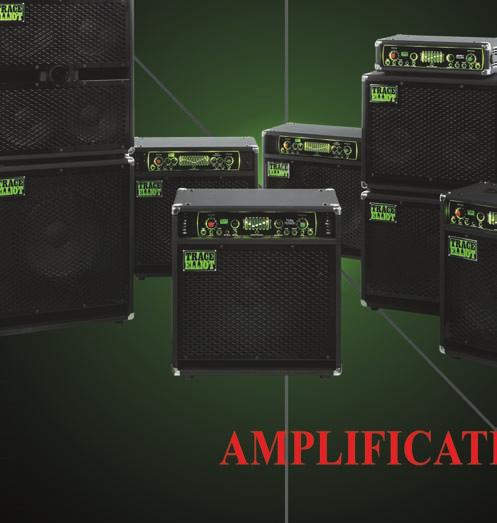
7 TRACE ELLIOT AMPLIFICATION Congratulations on your purchase of a Trace Elliot product. Our experience in design and quality of manufacturing will ensure that you will be able to rely on this product to deliver the solid professional sound you deserve, whether in the studio or on stage. This Trace Elliot range is the latest evolution of a line of products that were always known for their sophisticated features, high quality construction, use of state of the art technology and reliability. Many of the original ideas have become industry standards and are included within this range, however, around these are even more features to inspire musicians to create the music that they want to hear. The range features two types of preamp simply called 12 Band and 7 Band. This refers to the number of frequency bands of control within the graphic equalizer. There are several differences between the two preamp sections which are outlined below. In addition to the preamp, different models have different rear panel features, different power levels and, in the case of the combos, different speaker configurations. High quality parts have been used throughout. In keeping with traditional Trace Elliot amplifiers, the INPUT GAIN and OUTPUT LEVEL controls use parts that have detents to give a professional feel. All the switchable features on these amplifiers are split into two types: pre-set and performance. Pre-set functions are those which will be set at the start and are unlikely to be changed again during a performance. These all use latching type switches which means they have an in and an out setting and will click when changing settings. Performance functions are those which it is likely the user will want to switch on or off throughout a performance. These all use non-latching type switches which ultimately control FETs to switch the particular function on or off. The switching is extremely quiet and therefore will not be heard during a performance. The front panel switch does not click when pressed and only needs to be pressed lightly to operate. In all cases the appropriate LED for that function will be lit/unlit as it is switched. All these functions are also conveniently footswitchable using the supplied footcontroller. When a part of the circuitry is switched off then that particular part is completely bypassed, retaining signal integrity. Also, correct signal phase is maintained from all outputs regardless of which functions are switched on or off. Caution: Please look over this guide and read any caution or warning statements found within. Following these warnings is crucial to your personal safety and the safety of your Trace Elliot product. 4
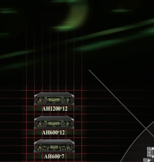
8 BASIC COMPARISON OF REATURES: 7 Band 12 Band LED level indication Yes Yes HI / LO sensitivity switch Yes Yes TUNER OUT Yes Yes PRE SHAPE circuit Yes Yes DI OUTPUT on front Yes No VALVE DRIVE circuit No Yes 7 BAND GRAPHIC EQUALIZER Yes No 12 BAND GRAPHIC EQUALIZER No Yes COMPRESSOR Yes No DUAL BAND COMPRESSOR No Yes SERIES EFFECTS LOOP Yes No MULTI OPTION EFFECTS LOOP No Yes DI OUTPUTS on rear No Yes MUTE switch Yes Yes 4 function footcontroller Yes No 6 function footcontroller No Yes Brightness Control for front panel Yes Yes QUICK START: This section is for people who are either too excited or too impatient to read the whole manual before using their new Trace Elliot. Please at least read this first section thoroughly and return to the rest of the manual later, lest you don t get the full potential out of your new amplifier. (1) Once you unpack your Trace Elliot, plug the power cord into the socket on the rear panel and connect to a mains socket supplying the proper AC line voltage for your unit. This is located on the rear of the unit, near the mains inlet and power switch. (2) If your unit is an amplifier head (e.g. AH600-7, AH , etc.) then connect the speaker output to your speaker cabinet(s). (More information on this is provided in the Owner s Guide for the cabinet). (3) Turn the OUTPUT LEVEL control to the 0 position. (4) Connect the footcontroller (included) to the EXTERNAL CONTROL socket on the rear panel using the eight-pin DIN cable (included). (5) Plug your instrument into the INPUT on the front panel using a high quality shielded instrument cable and turn the INPUT GAIN control to the 0 position. (6) Flip the power switch on the rear to the ON position to turn the unit on. (7) Set your instrument to your normal settings and while striking a string hard turn up the INPUT GAIN gradually. While doing this observe the level indication LEDs above the control. When the red LED starts to be lit, turn the INPUT GAIN control back one or two clicks so that it only lights up very occasionally. 5
9 (8) Now gradually turn up the OUTPUT LEVEL control. Do this slowly to avoid any sudden level changes that could damage your hearing; these are loud amps! Set this at the desired playing volume. (9) You will notice that the unit will have defaulted to a setting of everything off except the PRE SHAPE circuit. This is so that whenever the unit is turned on it will power up with a good basic tone. (10) Make music! Feel free to turn on and off the other features on the unit, either by the footcontroller or the front panel, and make adjustments to the other controls to get an idea of the flexibility of the unit. While making adjustments keep an eye on the level indication LEDs; some extreme settings of the Graphic Equalizer will increase the signal level into clip, if this happens simply re-adjust the INPUT GAIN control as mentioned above. 6

10 IN DEPTH GUIDE Well done! The very fact that you are reading this section means that you are serious about getting the most out of your Trace Elliot amplifier. Although fundamentally easy to use, this guide will hopefully explain the features of your amplifier in a way that will unlock all sorts of sonic potential that may have otherwise remained hidden. This operating guide covers the features of all the contemporary 12 Band and 7 Band range of amplifiers. If a feature is only applicable to particular units then these are shown in brackets next to the heading. Therefore, if (12 Band) is shown, this section applies to all 12 Band products and not to any 7 Band products. Where a specific model is shown in brackets, e.g. (AH ), then this applies only to that product. The feature being explained is shown in upper case, the type of control is shown in lower case. If there are any terms you do not fully understand then please refer to the glossary at the back of this manual. FRONT PANEL There are two different front panels used for the range. Aesthetically they are very similar, however closer inspection shows there are several differences. The 7 BAND has all its primary features on the front, with very little on the rear, whereas the 12 BAND has many of its features moved to the rear to make space for other features on the front. Basically the operation is very simple. The signal flow runs from left to right through the functions on the front panel. The status of each function is clearly shown by the corresponding controls and LEDs, which also match the LEDs on the footcontroller. 7
11 (1) INPUT socket This is to connect the 1/4 jack lead from your instrument. Alternatively, if any effect units are being used before the amplifier then the output from the last unit is connected here. When the INPUT is not in use the amplifier is automatically muted to prevent any unwanted noise. Experience has shown us that not all 1/4 jack plugs are made equal, therefore, we recommend the use of only high quality 1/4 jack leads for best sonic performance and reliable connection. (2) HI / LO switch This switch has two functions; to set the sensitivity and the impedance of the INPUT stage. In the out position it is set HI for high sensitivity and high impedance (1MΩ). The in position is the LO setting for lower sensitivity and lower impedance (100KΩ). The difference in sensitivity is 10dB. Actual sensitivity is dependent on the setting of the INPUT GAIN control. Generally, this switch should be set to HI for passive instruments, which are usually high impedance and have lower outputs, and LO for active instruments (those with batteries built in), which are low impedance and often have higher outputs. However, either can be used as long as the INPUT GAIN is set correctly. (3) INPUT GAIN rotary control This is to set the gain of the input stage of the amplifier. The setting of this control is the single most important on the whole unit, hence why the control knob has a red cap. (4) Signal level LEDs The level indication LEDs are included to help the user set the INPUT GAIN control. The circuitry monitors several strategic points throughout the preamp to determine if clipping (distortion) is occurring. The 7 Band units have 3 LEDs; green, yellow and red. Green will be lit for very low signal levels, yellow will also come on when higher levels are present, and the red will be lit when the level is clipping or close to clipping. The 12 Band units have 5 LEDs. An extra green LED shows low to medium signal levels and the additional red LED is a peak indicator that remains lit for a few seconds, even if the signal has dropped in level. This is to show where clipping is occurring momentarily and might otherwise be missed. Ideally, the INPUT GAIN control should be set as high as possible with the red LED(s) only lighting very occasionally when playing the instrument at its hardest. The basic procedure is as follows:- 1) Set the OUTPUT LEVEL to 0. Connect your instrument to the INPUT. 2) Set the HI / LO switch as appropriate for the particular bass being used. 3) Set the Volume control on the instrument to maximum. 4) Play the instrument as hard as it would be played during the performance. 5) While playing gradually turn up the INPUT GAIN. 6) The LEDs will begin to light up starting from the left. 7) Continue to turn up the INPUT GAIN until the (first) red LED is momentarily lit on the hardest strokes, then back off slightly one or two clicks on the control. 8
12 If an active bass is being used with the HI / LO switch set to LO and the INPUT GAIN control is turned fully clockwise without the red LED lighting at all, then switch to HI and follow the same procedure. This is because not all active basses have high enough outputs to require the LO setting to be used. While making adjustments to the rest of the controls keep an eye on the level indication LEDs. Some extreme settings of the graphic equalizer will increase the signal level into clip. If this happens simply readjust the INPUT GAIN control as mentioned above. (5) TUNER socket (7 Band) This is an output for connecting to a tuner. It is a buffered version of the input signal. Simply connect a 1/4 jack lead from this to a tuner and you will be able to tune up easily at any time without degradation to the tone. The signal from this socket is present all at times regardless of any other settings including MUTE. (6) PRE SHAPE switch This activates the circuit for the classic Trace Elliot Mid Pre-Shape that all users of previous Trace Elliot graphic style amplifiers will recognise immediately. As it is our signature sound, these amplifiers are designed to default to this setting when initially turned on. When this is activated the yellow LED is lit. The actual effect of this circuit is to boost the low and high frequencies (55Hz and 2kHz to 5kHz respectively) and to cut the mid frequencies (centred around 400Hz), giving an instant, clearly defined, punchy sound. It can be switched on and off using the front panel switch and also from the footcontroller. Both have a yellow LED to show its status. (7) VALVE switch (12 Band) This switches the VALVE circuit on or off. (8) DRIVE rotary control (12 Band) This sets the signal level that is sent into the VALVE circuit. (9) BLEND rotary control (12 Band) This controls the mix between the normal sound and the sound from the valve. The VALVE section uses both halves of an ECC83/12AX7 thermionic valve and is configured to be in parallel with the normal signal. Low settings of the DRIVE control will remain basically clean but with valve warmth added due to the harmonics generated by the valve. Higher settings will drive the valve harder and will result in overdrive sounds being created. The BLEND control can then be used to literally blend together the two parallel signals to achieve the desired effect. With the BLEND control fully anti-clockwise only the normal signal will be present; turning clockwise will reduce the normal signal and increase the valve sound until, with the control fully clockwise, only the valve sound is present. This means that in all positions, other than maximum and minimum, the sound of the valve is blended together with the normal, clean signal which prevents the bottom end losing definition. 9
13 By using the two controls a wide range of valve sounds can be dialled in, from vintage warmth to heavy overdrive. Bear in mind this is not simulation, this is a real valve doing a real job. We recommend experimenting with both the PRE SHAPE and GRAPHIC EQ in various settings while the VALVE circuit is switched on. With PRE SHAPE selected and a low to medium amount of DRIVE, the sound takes on the character of a vintage valve bass amp due to shaping the signal before the valve. With higher DRIVE settings the tone often benefits from some sound sculpting by the GRAPHIC, a little boost in the high mids helps the attack. Also the COMPRESSOR can be used to further shape the tone. The HIGH BAND is of particular use when lots of overdrive is being produced due to the extra high frequency content in the sound. Basically, this is a very versatile circuit that can produce various valve tones, from demurely subtle to wantonly filthy! Experiment and enjoy. Once a particular sound is found, the user can switch to the normal, clean sound and back again by pressing the associated switch on the front panel or by using the footcontroller, both of which have a red LED to show its status. Please note: to drive the valve hardest the INPUT GAIN control needs to be set correctly as described above. (10) DI OUT XLR socket (7 Band) This is a low impedance balanced output for connecting direct to a stage box or mixer for live or studio use. It gives the engineer a strong, clean signal without any overspill from other instruments. The XLR socket is wired as normal: pin 1 = Ground, pin 2 = Signal +, pin 3 = Signal (An Earth Lift switch is featured on the rear panel - see below). (11) PRE/POST switch (7 Band) This switches the signal that appears at the DI OUT from PRE with the switch out, to POST with the switch in. PRE is before any EQ is applied, therefore a higher level, buffered, version of the input signal. POST is after the EQ, COMPRESSOR and effects loop, but before the OUTPUT LEVEL control. Therefore, any sound shaping that is applied within the amplifier will be heard on the DI signal as well. Different applications will determine different settings. If in doubt choose POST as this will be basically the same sound that will be heard from the cabinet / combo speakers. Both settings should have similar general output levels. Neither will be affected by adjustments to the OUTPUT LEVEL, so turning up on stage will not overload the mixing desk once it is set. In either setting the output will be muted if the MUTE function is used. (12) GRAPHIC EQUALIZER switch & sliders When switched on the GRAPHIC EQUALIZER will be inserted into the signal chain. The green LED above the sliders shows its status. It can be switched on and off using the front panel switch and also from the footcontroller. The graphic equalizer is the centre piece, both functionally and quite literally, of a traditional Trace Elliot amplifier, so much so that the actual name for each part of the range is derived from the number of frequency bands within each one, i.e. 7 Band and 12 Band. Both types are very powerful tools for controlling the tone of your instrument. The design of a Trace Elliot graphic equalizer is very different from a standard sound reinforcement EQ. 15dB of cut or boost is available for each band, but instead of being spread mathematically over the frequency range they have been set at carefully selected frequencies of particular use for bass guitar. 10
14 Therefore, there is more control in the lower frequencies. Another difference is that each slider controls a much wider frequency range than normally found. These design differences are in common with traditional Trace Elliot amplifiers and are part of the sound. With the controls all set at 0dB (their mid click position), no change is made to the signal. Moving a slider up will progressively increase, or boost, the frequencies centred around the frequency marked above the slider. Moving a slider down will progressively decrease, or cut, the frequencies. Due to the flexibility and massive cut and boost available, it is important to know how to get the best from the circuit. Do not boost or cut all frequency bands. This will have the same effect as increasing or decreasing the overall volume level without affecting the tonal characteristic of the sound. Do not use excessive bottom (30Hz to 40Hz) boost on the graphic unless your speakers can handle it. Very few speaker systems are capable of handling frequencies as low as 30Hz and 40Hz with any degree of efficiency. Boosting at 30Hz, for instance, will not add to the perceived amount of bottom end in the sound, it will only make your speakers flap to no useful effect. In fact, boosting at 100Hz or 180Hz will have the apparent effect of adding far more bottom end than boosting at 30Hz, 40Hz or even 60Hz. The 30Hz slider has been provided on the 12 Band to allow precise tailoring at very low frequencies. This slider should be used to cut (not boost) the 30Hz to a level that allows the speaker system to work at its maximum efficiency. Do not use excessive top (10Hz to 15kHz) boost, this will add mostly hiss to the sound as there is very little signal output at this frequency from a bass. Try to keep the graphic sliders balanced around 0dB and in a smooth flowing curve from one slider to the next, and remember that after adjusting the graphic you may need to re-set the INPUT GAIN. The fundamental frequency range of a regular, 4-string bass guitar is from 41.2Hz (bottom E string) to around 392Hz (two octaves up on the G string) - not a very wide range. Obviously a lot of harmonics are produced when playing and these can extend up to 5kHz and more. The attack portion of the note also produces other high frequencies when the string is first struck. This attack can be emphasised by boosting the top end. However, because of the fairly small range of frequencies from a bass, by top end we mean between 2.5kHz and 5kHz. You will find that by boosting at 5kHz the attack will be emphasised, whereas boosting at 1.3kHz and 2.6kHz will bring out the harmonics in the note. Above this frequency range you will find it is better not to boost the signal as this will mainly emphasise any hiss present. If the VALVE circuit on a 12 Band unit is used at quite high DRIVE settings, you will find the GRAPHIC EQ extremely useful in shaping the overall tone due to having far more precise control than a simple bass, middle, treble arrangement found on many other amplifiers. (13) COMPRESSOR switch and rotary control (7 Band) Pressing this switch will add the COMPRESSOR to the signal chain. The blue LED above the switch shows its status. It can also be switched on and off using the supplied footcontroller. The rotary control adjusts the amount of compression applied to the signal; the further clockwise the control is set, the more the dynamic range will be squeezed. 11
15 The compressor in the 7 Band series uses studio quality, dedicated dynamics controller integrated circuits and has been specifically designed for bass guitar due to the common problems often experienced when using a normal, single band compressor in this application. With a standard compressor, the transition from non-compressed to compressed, i.e. crossing the threshold, can often be abrupt and unnatural sounding, especially at high ratio settings. Also, the normal pre-set attack and release times always have to be a compromise between having it work fast enough to catch rapidly changing signal levels (i.e. transients such as slapping techniques) or too fast which can cause low frequency distortion. To tackle these issues, the compressor on the 7 Band range has been designed as a soft-knee compressor with programme dependant adaptive attack and release times. Soft-knee means that, above the threshold, compression is applied gradually, with the ratio increasing as the input level goes up. The result is a smoother sounding compression than the normal hard-knee type. Adaptive attack and release means that these settings are automatically and constantly adjusted by the circuitry depending on what is being played. It will adjust to be slow to prevent distortion at low frequencies and then readjust to be fast to catch transients. It enables a bass player to switch between various playing styles such as finger style, slapping or plectrum, and the compressor will self-adjust its attack and release times accordingly. The simple single control makes setting the desired amount of compression easy as it is effectively controlling the threshold, ratio and make-up gain simultaneously. This is considerably less complicated than setting up a studio compressor from scratch as most of the hard work has been done by our engineers and incorporated into the circuitry. The circuit has been tuned so there should be little nominal signal level difference when switching the COMPRESSOR on and off, however this is dependant on the correct setting of the INPUT GAIN control. If you find that the level increases too much when switching the COMPRESSOR on, then slightly turn up the INPUT GAIN. The opposite applies if the compressed sound is too low. Compression is good for generally controlling the dynamic range and preventing distortion, and also as an effect. It sounds great for slapping techniques, for making harmonics more prominent, and for fattening up grooves or smoothing out notes in a run. Please be aware that due to the nature of any compression circuit that then adds make-up gain to bring the nominal level up, dialling in high levels of compression will increase high frequency hiss between notes. This is not hiss added by the compressor circuit, but hiss that is already present in the signal and then being amplified. However, as this is only really noticeable when not actually playing, if high levels of compression are desired it is possible to prevent the noise from being heard too much by using the footcontroller to turn off the compression or muting the signal when nothing is being played. (14) COMPRESSOR switch (12 Band) Pressing the switch will add the dual band COMPRESSOR to the signal chain. The blue LED above the switch shows its status. It can also be switched on and off using the supplied footcontroller. (15) LOW BAND rotary control (12 Band) This adjusts the amount of compression applied to the low frequencies in the signal; the further clockwise the control is set, the more the dynamic range of the low end will be squeezed. 12
16 (16) HIGH BAND rotary control (12 Band) This adjusts the amount of compression applied to the high frequencies in the signal; the further clockwise the control is set, the more the dynamic range of the high end will be squeezed. The compressor section of the 12 Band series uses two separate studio quality, dedicated dynamics controller integrated circuits, and has been specifically designed for bass guitar due to the common problems often experienced when using a normal, single band, compressor in this application. With a standard compressor, the transition from non-compressed to compressed, i.e. crossing the threshold, can often be abrupt and unnatural sounding, especially at high ratio settings. Also the normal pre-set attack and release times always have to be a compromise between having it work fast enough to catch rapidly changing signal levels (i.e. transients such as slapping techniques) or too fast which can cause low frequency distortion. To tackle these issues, the compressor on the 12 Band range has been designed as a dual band, soft-knee compressor, with different attack and release times pre-set for each of the high or low bands, and separate controls for the user to set the amount of compression applied to each band. Dual band means that the signal is split into the high and low frequencies, each of which then goes through separate compression circuits before being reconstructed. The amount of compression of each band can be set by adjusting the LOW BAND and HIGH BAND controls. This is similar to the sophisticated type of compression that is used for mastering whole tracks to prevent unwanted pumping and breathing effects. Soft-knee means that, above the threshold, compression is applied gradually, with the ratio increasing as the input level goes up. The result is a smoother sounding compression than the normal hard-knee type. Different attack and release times are pre-set for each band so that the low band works slow enough to prevent distortion at low frequencies and the high band works fast enough to catch transients. The simple single control for each band makes setting the desired amount of compression easy as it is effectively controlling the threshold, ratio and make-up gain simultaneously. This is considerably less complicated than setting up a studio compressor from scratch as most of the hard work has been done by our engineers and incorporated into the circuitry. The circuit has been tuned so there should be little nominal signal level difference when switching the COMPRESSOR on and off, however, this is dependent on the correct setting of the INPUT GAIN control. If you find that the level increases too much when switching the COMPRESSOR on then slightly turn up the INPUT GAIN. The opposite applies if the compressed sound is too low. In this application a dual band compressor has several uses. If used solely for controlling the dynamic range, it enables the bass player to switch between various playing styles, such as finger style, slapping or plectrum. The circuit will compress as directed without distortion to the bottom end, or transients taking hold of the whole signal level and causing pumping, which is very obtrusive on bass guitar. Applying compression to just the low band will fatten up the bottom end without losing the attack characteristics. It is a less processed sound than full range compression and works well in controlling the low frequencies, allowing higher volumes without stressing power amps or speakers. It can also help to add definition to notes within a run without loss of the attack dynamics. 13
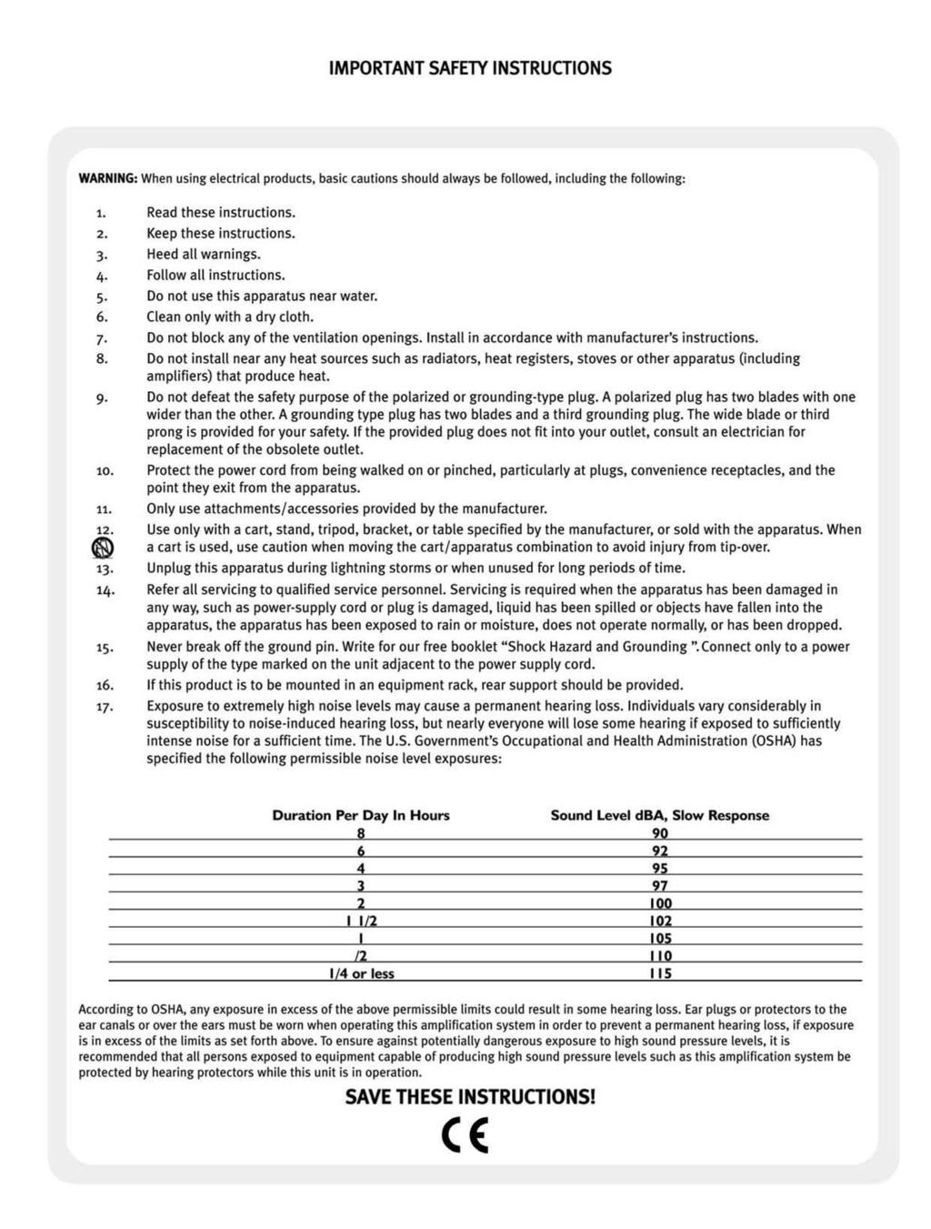
17 Compression applied to the high band will directly effect the attack portion of the note and should be used carefully. However, even extreme settings can produce some interesting effects for both slapping and fretless techniques and will help to make harmonics jump out in the mix. If the VALVE drive circuit is being used at high settings then the high band compressor can be used to control and smooth out the overdrive produced resulting in quite a processed, produced sound. Experimentation with many different settings of the compressor will help to get the most out of it. Please be aware that due to the nature of any compression circuit that then adds make-up gain to bring the nominal level up, dialling in high levels of compression will increase high frequency hiss between notes. This is not added by the compressor circuit, but is hiss that is already present in the signal and is then being amplified. However, as this is only really noticeable when not actually playing, if high levels of compression are desired it is possible to prevent the noise from being heard too much by using the footcontroller to turn off the compression or mute the signal when nothing is being played. (17) SEND socket (7 Band) This is a 1/4 jack socket for connecting to the input of effects units. (18) RETURN socket (7 Band) This is a 1/4 jack socket for connecting to the output of effects units. The effects loop on the 7 Band range is an easy to use, unity gain, series effects loop. The user can simply connect effects units between the SEND and RETURN sockets and the effect will be applied to the whole signal. The normal bypass on each effect unit can still be used to turn the effect on and off during a performance. The nominal level has been set to -10dBV to be able to drive most commonly used effects units. If the effects units have their own level controls, please ensure these are set correctly to prevent distortion occurring anywhere in the overall system. (19) LOOP switch (12 Band) Pressing the switch adds the EFFECTS LOOPS in to the signal chain. Its status is shown by the orange LED and it can also be controlled by the footcontroller. All the connections for EFFECTS LOOPS are on the rear panel. See below for a full description. (20) MUTE switch Pressing this switch will mute all outputs, (speaker, line and DI) except for the TUNER output. Its status is shown by the red LED above the OUTPUT LEVEL control which will flash when MUTE is selected. It can also be operated using the footcontroller. The MUTE function is useful for preventing unwanted noise between songs, when changing instruments or, if a tuner is connected to the TUNER output, for tuning up silently without needing to make adjustments to any other controls. The signal level indicators remain active when in mute so it is possible to change basses and set up the INPUT LEVEL silently without turning the OUTPUT LEVEL to zero and therefore risk forgetting the setting. (21) OUTPUT LEVEL rotary control This sets the signal level sent to the power output stage and the LINE OUT(s). It should be set at 0 when switching on the amplifier and turned up to the desired playing volume slowly to avoid any sudden level changes that could damage your hearing. 14
18 The actual power level produced from the amplifier will be dependent on the input signal and the settings of the other controls. Once set for a performance it can be left alone and the MUTE function can be used to turn the signal off between songs or sets. We also recommend turning the OUTPUT LEVEL control to 0 at the end of a session, before switching off. (22) Multi-purpose red LED above OUTPUT LEVEL This LED has several functions. Firstly, it will flash on and off if the MUTE function is selected. It will also light momentarily if maximum output from the power stage is reached. It also functions as a general protection warning light, illuminating if any of the following conditions occur: power amp over-temperature protection, short-circuit protection, over-current protection. If this LED remains lit please refer to the HELP section at the back of this manual. (23) LINE OUT socket (7 Band) This is an unbalanced jack output that can be used to send the output of the preamp section to another piece of equipment, such as a power amplifier, mixing desk or recording device. The actual level is dependent on the setting on the OUTPUT LEVEL control, which means that if it is used to expand the system with extra power amps and speakers, then the overall volume can still be set by a single control. 15
 EXTERNAL CONTROL 8 pin DIN socket(s) BFC-4 (7Band), BFC-6 (12 Band) The socket(s) are for connecting to the footcontroller supplied with the unit.")
19 REAR PANEL 7 BAND 12 BAND N.B. Within the 7 Band and 12 Band ranges the rear panels may vary slightly from those shown above. (24) EXTERNAL CONTROL 8 pin DIN socket(s) BFC-4 (7Band), BFC-6 (12 Band) The socket(s) are for connecting to the footcontroller supplied with the unit. It should be connected before the unit is switched on. Please ensure that the lead is inserted firmly and securely into the sockets on both the amplifier and the footcontroller. 7 Band units are supplied with a 4-function footcontroller (BFC-4) that enables the user to control PRE- SHAPE, GRAPHIC, COMPRESSOR and MUTE. The 12 Band units are supplied with a 6-function footcontroller (BFC-6) that enables the user to control PRE- SHAPE, VALVE, GRAPHIC, COMPRESSOR, LOOP and MUTE. The LEDs on both footcontrollers all correspond in colour and function to those on the front panel. If a footcontroller is disconnected from the amplifier while it is on and then reconnected, it may display different settings to the front panel. 16
20 To re-synchronize the switching simply turn the unit off for 5 seconds and then back on. Both the amplifier and footcontroller will power up in the normal default state of PRE-SHAPE on, all other functions off. The 12 Band units have been designed with two EXTERNAL CONTROL sockets. These make it possible to use two footcontrollers, either of which can control the amplifier. This is useful if performing on a large stage where each footcontroller can be placed in a different location for the performer s convenience. Alternatively, one of the controllers could be placed on stage as normal and the other placed at the side of the stage to enable a technician to control the musician s amplifier if necessary. Again, this is useful on particularly large stages. Another use for both sockets is if two amplifiers are being used. In this scenario the two amplifiers can be controlled by one footcontroller by connecting the spare EXTERNAL CONTROL socket on the first unit to one of the sockets on the second. (25) DI EARTH LIFT switch Pressing this switch in will disconnect the earth/ground connection from pin 1 on the DI output XLR socket(s). Usually this should be left in the out position however there may be certain situations when connecting from the DI socket(s) to another device that a hum is produced due to an earth/ground loop. If this happens then pressing the EARTH LIFT switch in should eliminate the problem. EFFECTS LOOPS (12 Band) (26) SEND LO PASS, FULL, HI PASS sockets (12 Band) These are all SEND outputs within the EFFECTS LOOPS section and are active at all times. The FULL SEND will output the full frequency range of the signal. The LO PASS SEND will output only the low frequencies and the HI PASS SEND will output only the high frequencies. The filters have been designed so that when the LO PASS and HI PASS signals are reconstructed they will be identical in both frequency response and phase. (27) SERIES / PARALLEL switch (12 Band) This configures the effects loops to be either SERIES, with the switch in where the whole signal passes through the effects loop, out of the sends and back in the returns, or PARALLEL with the switch out, where the signal is split, one part going through the effects loop and the other, dry, signal being unprocessed and mixed in with the effected signal. The PARALLEL setting ensures that a part of the overall signal remains pure and unaffected. If the PARALLEL setting is chosen it is recommended that the dry signal in the effects unit is turned to minimum if accessible. (28) RETURN LEFT, MONO, RIGHT/MONO sockets (12 Band) These are all RETURN inputs within the EFFECTS LOOPS section. The MONO socket will route the signal through both channels of the rest of the preamp. The LEFT socket will route the signal to the left channel. The RIGHT/MONO socket will route the signal to the right channel if the LEFT socket is also in use, or it will route the signal through both channels, i.e. in mono, if the LEFT socket is not used. 17
21 (29) LOOP LEVEL rotary control (12 Band) This sets the overall level of the signal while the LOOP is on. Therefore, if the LOOP is not selected this has no effect, but when the LOOP is selected this is a very important control for balancing the levels. The control has been calibrated so that if a simple loop is set up, SERIES, FULL RANGE, MONO, then with the control at the 12 o clock setting there will be unity gain when switching the LOOP on and off. Turning the control anti-clockwise will reduce the level when LOOP is selected, clockwise will increase the level. If the LOOP is selected and the LOOP LEVEL is at 0 then there will be no output. A wide range of level is available due to the many permutations of effects configuration. If in any doubt, set this to the 12 o clock setting and then adjust either way to balance the level with the dry signal. The EFFECTS LOOPS section is a highly sophisticated design with multiple sends, returns and other controls that allow myriad combinations of connection to external devices and, therefore, all sorts of sonic potential. The nominal level has been set to -10dBV to be able to work with most commonly used effects units. If the effects units have their own level controls please make sure these are set correctly to prevent distortion occurring anywhere in the overall system. Effects themselves aren t to everyone s taste, but that doesn t mean this feature won t be useful. These features have been designed for use as anything from a simple boost function to a means to connect to multiple different external devices. Here are some suggested uses/configurations, some using effects and others not:- Volume Boost: simply set the LOOP for PARALLEL setting and turn up the LOOP LEVEL. Switching the LOOP in will give up to 6dB of boost. Useful for solos. Simple Full Range Series Loop: connect FULL SEND to input of effects unit, MONO RETURN to output of effects unit, switch to SERIES with LOOP LEVEL at 12 o clock. Switching the LOOP in will route the signal through the effects unit at unity gain. Stereo Loop with Chorus on high frequencies: connect HI PASS SEND to input of Chorus unit, connect LEFT and RIGHT RETURNS to outputs of Chorus unit. Set dry signal on Chorus unit to minimum. Switch to PARALLEL and set LOOP LEVEL to 12 o clock. Switching LOOP on will apply stereo Chorus to the upper frequencies while keeping the low end mono and clear. Similar set up can be used for Flanging, Phasing, etc. Improved Octaver triggering: connect LO PASS SEND to input of Octaver, connect MONO RETURN to output of Octaver. Set dry signal on Octaver to minimum. Switch to PARALLEL with LOOP LEVEL at 12 o clock. Switching LOOP on will add the Octaver effect as expected but as the signal being sent to it has far less harmonics the Octaver will be able to produce a clearer more stable tone. Stereo Chorus on high frequencies, Octaver on low: connect both pedals as per the last two configurations. Switching LOOP on will add both effects in parallel therefore enabling both to work without interfering the other. 18
22 Overdrive/Distortion just on high frequencies: connect HI PASS SEND to input of Overdrive/Distortion unit, connect MONO RETURN to output of Overdrive/Distortion unit. Switch to PARALLEL, LOOP LEVEL to 12 o clock. Set effect as desired. Switching LOOP on will apply Overdrive/Distortion to the upper frequencies while keeping the low end clear. Envelope Filters: try using an envelope filter triggered from the HI PASS SEND, try again triggered from the LO PASS SEND, this will produce different results. Got two envelope filters? Try triggering one from HI PASS, the other from LO PASS, bring their outputs back into LEFT and RIGHT and set one to filter up the other to filter down, weird enough? Now switch on the VALVE drive circuit to really give them something to get their teeth into! Inserting external audio source: connect outputs of external unit (synth, CD, sequencer, drum machine, etc.) into LEFT and RIGHT RETURN. Set to PARALLEL with the LOOP LEVEL at 12 o clock. Switching the LOOP on will mix the external audio source with the bass signal. Use the output level on the external source to balance the two. Effects Loop as a crossover (requires unit with two power amplifiers): connect patch leads from HI SEND to RIGHT RETURN and LO SEND to LEFT RETURN. Set to SERIES with LOOP LEVEL at 12 o clock. With LOOP selected all left outputs will produce the low frequencies, all right outputs the high frequencies. Triggering of external devices such as synth: connect the LO PASS SEND to input of device to be triggered. Signal will be present at all times and will have high frequency content removed therefore making it easier for the external device to determine the fundamental frequency. These are just a few ways in which the EFFECTS LOOPS connections can be used. The configurations are only limited by the equipment that is available and your imagination. Stereo/Mono? The 12 Band preamp is stereo from the EFFECTS LOOPS through to the LINE OUTS. Units with two output stages (e.g. AH ) remain stereo through to the speaker outputs. Units with one output stage (e.g. 1215, 1210) have the two channels mixed into mono at the final preamp stage. Therefore although the signal from the speaker output will be mono, the DI and LINE OUTs retain stereo separation for recording or sound reinforcement purposes. (30) TUNER socket (12 Band) This is an output for connecting to a tuner. The signal here is a buffered version of the input signal before any processing has been applied. Simply connect a 1/4 jack lead from this socket to a tuner and you will be able to tune up easily any time without any degradation to the tone. (As the actual level is determined by the INPUT GAIN, if you wish to tune up silently use the MUTE function, which mutes all outputs except TUNER, rather than adjusting the INPUT GAIN.) (31) BALANCED DI OUTPUTS LEFT, RIGHT, PRE EQ XLR sockets (12 Band) These are separate low impedance balanced outputs for connecting direct to a stage box or mixer for live or studio use. This gives the engineer a strong, clean signal without any overspill from other instruments. The XLR socket is wired as normal: pin 1 = Ground, pin 2 = Signal +, pin 3 = Signal The PRE EQ output is taken before any EQ is applied, therefore a higher level, buffered, version of the input signal. The LEFT and RIGHT outputs are taken after the PRE SHAPE, VALVE, GRAPHIC, COMPRESSOR and EFFECTS LOOPS, but before the OUTPUT LEVEL control. 19
23 Therefore, any sound shaping that is applied within the amplifier will be heard on the DI signal as well. Both settings should have similar general signal levels. Neither will be affected by adjustments to the OUTPUT LEVEL control so turning up on stage will not overload the mixing desk once it is set. All outputs will be muted if the MUTE function is used. Different applications will determine which output(s) to use. For a pure bass sound at all times the PRE EQ should be used. Alternatively, if all the internal processing is required then the LEFT and/or RIGHT should be used. If in doubt choose these as the sound will be basically the same as the sound heard from the cabinet/ combo speakers. If you are not using any stereo effects then it will only be necessary to use either LEFT or RIGHT as both will produce the same signal. There may also be some occasions when it is desirable to use all outputs. This is particularly useful when recording as it allows both the dry and processed signals to be recorded at the same time on to separate channels. These can then be switched between or even mixed together at later stages of the recording session. As they are fundamentally the same performance they will track seamlessly in pitch and phrasing. (32) OUTPUTS LEFT & RIGHT sockets (12 Band) These are unbalanced 1/4 jack outputs that can be used to send the output of the preamp section to another piece of equipment, such as a power amplifier, mixing desk or recording device. The actual level is dependant on the setting on the OUTPUT LEVEL control which means that if these sockets are used to expand the system with extra power amps and speakers, then the overall volume can still be set by a single control. (33) SPEAKER OUTPUT(S) All units feature Neutrik Combination Speakon and 1/4 jack sockets and most feature an additional 1/4 jack socket depending on the specific model. (The 715 combo only has the Combination Speakon socket so that the internal speaker must be disconnected to be able to connect to an extension cabinet). Units with two power stages (e.g. AH ) have separate speaker outputs for the LEFT and RIGHT channels. These sockets are for connecting to speaker cabinets. Connections should be made before mains power is applied to the unit. When connecting to a speaker cabinet we recommend that the Speakon socket is used in preference to the 1/4 jack as it provides a far superior connection. 1/4 jack sockets have been added merely for the user s convenience when it is absolutely necessary to use them. Please ensure that if a jack lead is used that it is definitely a speaker cable rather than in instrument cable; the two are very different and should not be mixed for either application. If two extension cabinets are used with 1/4 jack leads we recommend that each cabinet is connected back to the amplifier separately instead of using the LINK socket on the cabinet. This will halve the current that each lead carries and provide a better connection. Trace Elliot amplifiers are designed to deliver their rated RMS output power into 4 ohm speaker loads. Therefore each amplifier can drive 1x 4 ohm cabinet or 2x 8 ohm cabinets (in parallel). Driving a single 8 ohm load will deliver between 50% and 60% of the rated power. Never connect your amplifier to a speaker load lower than the rated 4 ohms. This will result in over heating of the amplifier and it shutting down into protect mode. Please refer to the specification sheet for your cabinet for more information on its use. 20


24 (34) FRONT PANEL BRIGHTNESS rotary control This literally controls the brightness of the back lighting on the front panel. Fully anti-clockwise will turn it completely off. This does not affect the brightness of the small status LEDs. The back lighting is produced by state of the art, high powered LEDs positioned behind the Perspex (plexiglass) part of the front panel and gives the familiar green glow of Trace Elliot amplifiers on stage. LEDs have been used as they do not produce any electronic noise or hum that could be detrimental to the sound. The control has been included to enable users to set the BRIGHTNESS to their taste and also to turn the back lighting off completely in situations where it would be undesirable. (35) POWER switch Once the whole system has been set up, set this to the ON or 1 position to apply mains power. The switch will be illuminated green when the unit is on. Switch to the OFF or 0 position at the end of normal use before any of the system is disconnected. (36) IEC socket and fuse holder This is to connect the supplied IEC mains power cord. The mains voltage that the specific unit is built to accept is marked on the rear panel. Before applying mains power please ensure that it is the correct voltage. For your safety we recommend that you use the mains cord provided. Other mains cords may contain lower value fuses that could blow at high volume and shut down the amplifier thereby spoiling a performance. The fuse tray within the IEC socket contains the mains fuse. If replaced it must be with the same type and rating as marked on the rear panel. Failure to do so may render the unit unsafe and invalidate the warranty. If the fuse repeatedly blows then consult your authorised Trace Elliot dealer, or a qualified service engineer. 21
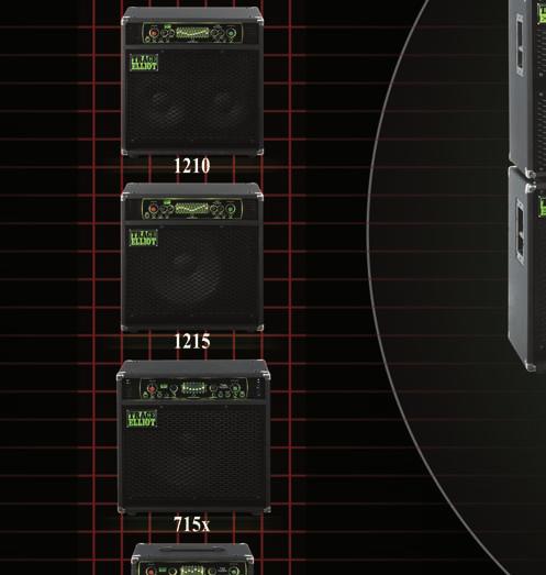
25 ADDITIONAL INFORMATION POWER AMPLIFIERS The power amplifier sections within these Trace Elliot products are high efficiency advanced designs. They are designed to withstand rigorous use and include protection for over-temperature, over-current and shortcircuits. Although designed to run comparatively cool, the high power versions do contain fans. These blow cool air from the outside across critical components and back out through the vents. Therefore, the vents on the front and rear or sides of these units should not be obscured. Please bear this in mind if you intend to rack-mount or flight-case your amplifier. ANTI-CLIPPING CIRCUIT To prevent prolonged power amplifier clipping which, apart from sounding highly offensive, is the easiest way to destroy speakers, the power amp sections are immediately preceded with a two-stage circuit to control the signal level from the preamp. The rear panel of each amplifier will show two RMS power ratings, one for transients and the other for steady-state signals. The circuit is inactive until the power level reaches the lower rating. At this point the first stage of signal amplitude control is applied. This works like a fairly slow compressor that is relatively unobtrusive and will gently control the signal level to keep it from clipping the power stage. To catch transients, a second stage is applied at the higher power level. Between the two stages the signal level is controlled to keep clipping to a minimum without the circuit being too audible in affecting dynamics. The 12 Band products incorporate a valve as part of this circuit. COMBOS Various combinations of preamp, power amp and speaker configurations are available within the range. The particular combination of your unit will be marked on the front panel. All the amplifier sections are designed to deliver their full rated power into 4 ohms. Therefore a combo fitted with a 4 ohm internal speaker will deliver the full power into its own enclosure. Although capable of driving extension cabinets, the connections on the rear mean that the user has to disconnect the internal speaker before connecting to an extension cabinet. Combos fitted with an 8 ohm internal speaker will deliver approximately 50% 60% of the rated power into their own enclosure. Connecting to an 8 ohm extension cabinet will bring the overall impedance down to 4 ohms and will therefore deliver 100% of the rated power. The connections on the rear of these combos allow an extension cabinet to be connected while keeping the internal speaker connected. This arrangement is ideal for using the combo on its own at rehearsals, recording sessions and smaller gigs, then connecting an extension cabinet, such as a 1518 or 1028H, to give more power when required at larger gigs. Combos fitted with switchable high frequency horn attenuation (e.g. 715X, 1215, 1210) benefit from the user being able to set the horn on full, half or disconnected. The setting will depend on playing and music styles, preamp settings and personal choice. On 12 Band units, when using the VALVE drive at high DRIVE settings it is advisable to experiment with the setting of the horn attenuation. Generally for more traditional warm or overdriven bass tones the horn should be set low or off. 22
26 HELP If you experience problems with your Trace Elliot unit please check the following before contacting an authorised Trace Elliot dealer, distributor or service centre. Symptom Unit does not power up Unit powers up but no sound Signal level LEDs do not light Check IEC mains cord is correctly connected. Fuse in IEC inlet is OK. Fuse in IEC mains cord is OK. All connecting leads. Instrument leads and battery if applicable. Signal level LEDs light but no sound OUTPUT LEVEL is turned above 1. Is MUTE or LOOP selected? If so, turn off. Leads in Effects Loop (7 Band). No signal when LOOP selected (12 Band) LOOP LEVEL is turned up. Unwanted distorted signal General purpose protection LED on Is it overheating? Is it set SERIES? Set to PARALLEL. Connecting leads in LOOP. External devices used in LOOP. Is INPUT GAIN set correctly? Reset. Is GRAPHIC set too extreme? Is battery in instrument OK? Check Speaker wiring. Ensure vents are clear. 23
27 24
28 25
29 26
30 SPECIFICATIONS Specifications 7 Band 12 Band INPUT sensitivity HI 77.5mV RMS (-20dBu) LO 245mV RMS (-10dBu) INPUT impedance HI LO PRE SHAPE Frequency Response 1MΩ 100kΩ 50 Hz Hz. 5kHz Slope = 6dB/octave GRAPHIC EQUALIZER +/- 15dB at 7 frequencies +/- 15dB at 12 frequencies COMPRESSOR Single band, soft knee, with adaptive attack and release times Dual band, soft knee, with specifically set attack and release times per band. EFFECTS SEND(S) Load impedance Nominal Output Level EFFECTS RETURN(S) Impedance Nominal input level 1KΩ or greater -10dBV, 0.3VRMS 100kΩ -10dBV, 0.3VRMS TUNER OUT level Instrument level via buffer Nominal -10dBV, 0.3VRMS LINE OUT(S) Load Impedance Level with OUTPUT LEVEL on 5 DI OUTPUT(S) Load impedance Nominal Output Level 1KΩ or greater 0dBu, 0.775VRMS 600Ω or greater 0dBu, 0.775VRMS EXTERNAL CONTROL 4 function footcontroller 6 function footcontroller VALVES n/a 2 x ECC83/12AX7 Double Triode DC filament supply HUM & NOISE FREQUENCY RESPONSE POWER AMPLIFIER Protection Minimum Load Power Output at 8 Ω Greater than 80dB below rated power +/-3dB, 20Hz-25kHz Current limit protection, thermal protection, anti-clip protection 4Ω, for full rated ouput power Approx 60% of rated power SUPPLY VOLTAGE Local nominal mains voltage (230/120/100) +/- 10% ACCESSORIES IEC lead, protective cover, footcontroller, owners manual 27
31 Combo Enclousure Specifications:- COMBO ENCLOSURE SPECIFICATIONS x Transducer Complement: 1 x 15 + Horn 1 x 15 + Horn 1 x 15 + Horn 2 x 10 + Horn Maximum Output Power 450W 600W 600W 600W Internal Speaker Power Handling: 300WRMS 500WRMS 500WRMS 400WRMS Nominal Impedance: 4Ω 8Ω 8Ω 8Ω Frequency Response: 40Hz 15kHz 35Hz 15kHz 35Hz 15kHz 35Hz - 15kHz Sound Pressure Level 1W, 1m 99dB 100dB 100dB 100dB Cabinet Tuning Frequency: 42Hz 42Hz 42Hz 40Hz Crossover Frequency (internal passive): n/a 5kHz 5kHz 5kHz Controls: - Horn switch Horn switch Horn switch Enclosure Materials & Finish 90% Poplar Ply, 10% MDF, Black vinyl covering, metal hardware Individual Woofer Spec:- Power rating 300W 500W 500W 200W Sensitivity 98dB 100dB 100dB 97dB Voice coil diameter 2 ½ (64mm) 3 (76mm) 3 (76mm) 2 (51mm) Magnet Weight 1.4kg / 50oz 2.2kg / 77oz 2.2kg / 77oz 1.2kg / 42oz Cone material Kevlar impregnated paper Horn Type Ceramic Tweeter Phenolic horn loaded dome tweeter DIMENSIONS & WEIGHTS Dimensions & Weights Width Height Depth Weight mm inches mm inches mm inches kg lbs x AH AH AH
32 GLOSSARY OF TERMS active adaptive attack & release attack buffered DI dry dual band compressor EQ FET hard-knee impedance LED make-up gain mastering parallel With regard to a musical instrument, one that has some kind of on-board preamp, usually easily determined by it having a battery inside. The attack and release times automatically adjust, i.e. adapt, to the frequencies and transients of the audio signal. With regard to compressors, the time it takes to react to an audio signal once it has exceeded the Threshold. A buffer circuit is one which electronically isolates one part of the circuit from another and produces a low impedance version of the input signal. Simple but very useful. Direct Inject. Direct cable connection between an amplifier and stage box/mixer/pa. A signal that is unprocessed, i.e. no effects have been applied. Effectively two separate compressors, one that works on the high frequencies and one that works on low. Equalizer or Equalization. Device that can modify the frequency response of an audio signal. Field Effect Transistor. A type of transistor that can be configured to be used as a very quiet switch for audio signals. Compression that is applied with a fixed ratio once that signal level exceeds the threshold. Can sound abrupt and unnatural. With regard to the input of an amplifier, the load it presents to the input signal. Alternatively, the load a speaker presents to the output of a power amplifier. Light Emitting Diode. A small electronic light used for level indication and function status. Gain added after a compressor to bring the nominal level up to approximately the same as before the compressor. The final part of the recording process where, amongst other things, multiband compression is used to optimize clarity, punch and dynamic range. Either when a signal is split and routed down two separate paths before being re-combined, or when speakers are connected + to + and - to -. Opposite of series. 29
33 passive pumping and breathing ratio release sensitivity series soft-knee thermionic valve threshold unity gain With regard to a musical instrument, one that does not have any form of onboard preamp, usually easily determined by it not having a battery inside. When a compressor is set to extreme settings and noticeable shifts in volume are caused by transients as the compressor can t keep up. Ratio between change in normal signal (in db) and change in compressed signal (in db). 10:1 means for 10dB increase of the normal signal there will be 1dB of increase in the compressed signal. The time it takes for a compressor to stop applying compression after a signal has decayed to be less than the Threshold. With regard to the input of an amplifier, the level of input signal required to achieve maximum signal swing within the unit. High sensitivity means even small signals will reach full swing, low sensitivity means larger signals are accepted before clip. Either when the whole signal is routed though a device or part of a circuit, or when speakers are connected + to -. Opposite of parallel. Compression that is applied gradually with an increasing ratio after exceeding the threshold. Often smoother sounding. A century old electronic device superseded by modern technology in nearly every area of electronics, notably not audio, where many of us still love the little glowy things. Usually contained within an air tight glass tube, hence also called vacuum tube. The signal level above which compression is applied. Gain of one, i.e. the signal is neither amplified nor attenuated and remains the same level. 30
34

35
Trace Elliot Elf Bass Instrument Amplifier
 Trace Elliot Elf Bass Instrument Amplifier Owner s Manual FCC Compliancy Statement This device complies with Part 15 of the FCC rules. Operation is subject to the following two conditions: (1) this device
Operating Instructions 1000RB
 Operating Instructions 1000RB Table of Contents INTRODUCTION. 3 1000RB FEATURES. 3 FRONT PANEL FEATURES 4 REAR PANEL FEATURES 5 HOOKING UP YOUR SPEAKERS 6 GETTING YOUR SOUND. 6 TROUBLESHOOTING.. 7 USING
Operating Instructions 2000RB
 Operating Instructions 2000RB Table of Contents INTRODUCTION. 3 2000RB FEATURES. 3 FRONT PANEL FEATURES 4 REAR PANEL FEATURES 5 SELECTING AN OPERATING MODE & HOOKING-UP YOUR SPEAKERS 6 GETTING YOUR SOUND.
The Alpha Omega 900 amplifies the best qualities of one of the most powerful and distinct Darkglass pedals ever made.
 OWNER S MANUAL The Alpha Omega 900 takes the best elements of our most successful distortion preamplifier ever, combined with state-of-the-art features to make a monstrous 900-watt amplifier with earth-shattering
AG C & AG C
 Aguilar Amplification s AG 500-112C & AG 500-212C Owners Manual August 2005, Manual Version 1.3 1. The AG 500-212C was designed to give bassists the versatility of the AG 500 bass head with the award winning
Redhead (Original 240 watt version)
") Redhead (Original 240 watt version) Please Note: The Redhead is no longer in production (it was upgraded in 1996). The text below is provided for the convenience of SWR users who purchased this model on
Redhead (Original 240 watt version) Please Note: The Redhead is no longer in production (it was upgraded in 1996). The text below is provided for the convenience of SWR users who purchased this model on
THANK YOU REGISTER ONLINE. ABM-EVO-IV - Front Panel Facilities
 ABM-EVO-IV - Front Panel Facilities PUT PUT STRUMENT LE PASSIVE/ACTIVE PUT LEVEL PUT PUTS THANK YOU Thank you for purchasing your Ashdown Engineering Amplifier and welcome to the family! We really think
KXR. Owner, s Manual. One hundred KEYBOARD EXTENDED RANGE TYPE: PR 262 P/N
 THE SOUND THAT CREATES LEGENDS KEYBOARD EXTENDED RANGE KXR One hundred TYPE: PR 262 Owner, s Manual P/N 047761 KXR 100 Owner s Manual Congratulations on your purchase of the Fender KXR 100 keyboard amplifier.
KXB800 BASS AMPLIFIER
 KXB800 BASS AMPLIFIER OWNER S MANUAL Congratulations on the purchase of your Kustom KXB800. This Bass Amp combines quality performance and convenient features in a sturdy, rack-mountable design. You ll
LeMay Audio Products. MK-I Preamplifier Users Manual John P. LeMay All Rights Reserved Rev A
 LeMay Audio Products MK-I Preamplifier Users Manual 2008 John P. LeMay All Rights Reserved Rev A 08.12.24 Congratulations on purchasing one of the world s finest professional instrument preamplifiers!
REIDMAR 750 PROFESSIONAL BASS HEAD USERS MANUAL. Introduction 2 Block Diagram 3 Front Panel Controls 4 Rear Panel Features 6 Specifications 8
 EBS REIDMAR 750 USERS MANUAL REIDMAR 750 PROFESSIONAL BASS HEAD CONTENTS Page Introduction 2 Block Diagram 3 Front Panel Controls 4 Rear Panel Features 6 Specifications 8 USERS MANUAL EBS REIDMAR 750 About
USERS MANUAL EBS MICROBASSII BLACK LABEL SERIES. EBS MicroBassII. EBS Professional Bass Equipment SPECIFICATIONS
 SPECIFICATIONS Nominal Input Level - 8 dbv Input Impedance 10 Mohms (Ch A), 1 Mohms (Ch B) Output Impedance 10 kohms Frequency Response +0 / -3 db 20 20 khz Tone Controls Bass +/- 15 db @ 100 Hz Treble
Laney DB SERIES USER MANUAL MODEL : DB150C DB150H DB300C DB300H DB400C DB400H
 Laney DB SERIES USER MANUAL MODEL : DBC DBH DBC DBH DBC DBH Laney INTRODUCTION Congratulations on your decision to purchase a Laney amplifier. Laney products are designed with ease of operation as a primary
Important Safety Information
 Owner's Manual Important Safety Information FCC Notice This equipment has been tested and found to comply with the limits for a Class B digital device, pursuant to Part 15 of the FCC Rules. These limits
B SERIES COMBO COMBO
 B B SERIES A S S COMBO -9 Hartke Table of Contents Introduction 1 B Series Combo Bass Amplifier Features 2 Guided Tour 3 Front Panel 3-4 Rear Panel 5 Setting Up and Using Your Hartke B Series Combo Bass
DBS Dynamic Bass System Head
 DBS 7400 Dynamic Bass System 7400 Head Marshall Amplification plc Denbigh Road, Bletchley, Milton Keynes, MK1 1DQ, England Tel: (01908) 375411 Fax: (01908) 376118 Web Site - http://www.marshallamps.com
T L Audio INDIGO SERIES. User Manual VP-2051 VALVE VOICE PROCESSOR. Tony Larking Professional Sales Limited, Letchworth, England.
 T L Audio INDIGO SERIES User Manual VP-2051 VALVE VOICE PROCESSOR Tony Larking Professional Sales Limited, Letchworth, England. Tel: 01462 490600. International +44 1462 490600. Fax: 01462 490700. International
VENUE Full Isolation D.I.
 VENUE Full Isolation D.I. USER S GUIDE www.lrbaggs.com INTRODUCTION Thank you for purchasing our Venue D.I. This is the first all-discrete acoustic guitar preamp to combine a transformer-coupled D.I. output
MAX Series Bass Amplifiers
 MAX Series Bass Amplifiers Operating Manual www.peavey.com FCC Compliancy Statement This device complies with Part 15 of the FCC rules. Operation is subject to the following two conditions: (1) this device
FEATURES FRONT PANEL. INPUT : Use this jack to connect your instrument via a standard ¼ mono cable.
 OWNER S MANUAL 2018 ended up as the most important year in Darkglass history. With groundbreaking new products, renewed classic releases, and limited-edition pedals, our product catalog grew stronger than
WORKINGMAN S WORKINGMAN S 12 WORKINGMAN S 15
 WORKINGMAN S SERIES BASS COMBOS OWNER S MANUAL INCLUDES: WORKINGMAN S 10 WORKINGMAN S 12 WORKINGMAN S 15 SWR SCOTTSDALE, AZ USA TABLE OF CONTENTS INTRODUCTION...................................................1
FEATURES FRONT PANEL. INPUT : Use this jack to connect your instrument via a standard ¼ mono cable.
 OWNER S MANUAL 2018 ended up as the most important year in Darkglass history. With groundbreaking new products, renewed classic releases, and limited-edition pedals, our product catalog grew stronger than
PHIL JONES BASS PJB BP-800
 PHIL JONES BASS PJB BP-800 OWNER S MANUAL Thank you for purchasing the PJB BP-800. A great deal of dedication and passion went into designing and building this no compromise, high-performance compact amplifier.
DSL1CR & DSL1HR OWNER S MANUAL
 DSL1CR & DSL1HR OWNER S MANUAL INTRODUCTION Congratulations on your purchase of this Dual Super Lead (DSL) amplifier from Marshall Amplification. The DSL provides the legendary Marshall tone, allowing
INTRODUCTION WARNING! IMPORTANT SAFETY INSTRUCTIONS. Congratulations on your purchase of this MG Gold amplifier from Marshall Amplification.
 OWNER S MANUAL INTRODUCTION WARNING! IMPORTANT SAFETY INSTRUCTIONS Congratulations on your purchase of this MG Gold amplifier from Marshall Amplification. The MG provides modern Marshall tones for the
FOR PERSONAL ASSISTANCE & SERVICE: Contact Tech 21 weekdays from 9:00 AM to 5:00 PM, EST. MADE IN THE U.S.A.
 POWER REQUIREMENTS *Operable with phantom power supply, minimum 24V DC regulated, however, 48V DC regulated is recommended in order to illuminate LED. *Utilizes standard 9V alkaline battery (not included).
FOR PERSONAL ASSISTANCE & SERVICE: Contact Tech 21 weekdays from 9:00 AM to 5:00 PM, EST.
 SansAmp Bass Driver DI (v2) Owner s Manual POWER REQUIREMENTS *Operable with phantom power supply, minimum 24V DC regulated, however, 48V DC regulated is recommended in order to illuminate LED. *Utilizes
RACKHEAD Dual Tube/Solid-State Channel Bass Amp
 RACKHEAD 1060 Dual Tube/Solid-State Channel Bass Amp Please read this manual and the enclosed safety pamphlet carefully before operating the amp! Technical specifications subject to change without notice.
CLASS A DUAL TRANSFORMER COMPRESSOR OWNER S MANUAL
 LIMINATOR CLASS A DUAL TRANSFORMER COMPRESSOR OWNER S MANUAL TABLE OF CONTENTS SECTION PAGE INTRODUCTION 2 INSTALLATION 3 FRONT PANEL CONTROLS 4 OPERATION 5 SPECIFICATIONS 7 WARRANTY AND REGISTRATION 8-1
NEOX T. Your new NEOX T Combo is designed with the power, features and performance that today s professional bassists desire.
 NEOX400-210T O W N E R S M A N U A L CONGRATULATIONS! Your new NEOX400-210T Combo is designed with the power, features and performance that today s professional bassists desire. The solid yet lightweight
Ai1 OWNER S MANUAL. Getting Started:
 Ai1 OWNER S MANUAL Thank you for your purchase. We have developed a quality DI with preamp for use by professional musicians with added features for home or private practice. Features: The Ai1 is a quality
THD FLEXI-50 INSTRUCTION MANUAL 1
 THD Flexi-50 Instruction Manual Thank you for your purchase of the THD Flexi-50 amplifier! The Flexi-50 is a precision hand-built 50-watt Class-AB amplifier with foot-switchable overdrive/boost, footswitchable
Fender Musical Instruments 7975 North Hayden Road, Scottsdale, Arizona U.S.A.
 Fender Musical Instruments 7975 North Hayden Road, Scottsdale, Arizona 85258 U.S.A. Since 1946, Fender realized the importance of your amplifier. You see, your amplifier is more than just a combination
HQ-31 HQ-15 USER S GUIDE SINGLE CHANNEL 31 BAND 1/3 OCTAVE GRAPHIC EQUALIZER DUAL CHANNEL 15 BAND 2/3 OCTAVE GRAPHIC EQUALIZER
 HQ-31 SINGLE CHANNEL 31 BAND 1/3 OCTAVE GRAPHIC EQUALIZER HQ-15 DUAL CHANNEL 15 BAND 2/3 OCTAVE GRAPHIC EQUALIZER USER S GUIDE GENERAL INFORMATION SINGLE CHANNEL 31 BAND 1/3 OCTAVE GRAPHIC EQUALIZER WITH
DSL100HR & DSL40CR OWNER S MANUAL
 DSL100HR & DSL40CR OWNER S MANUAL INTRODUCTION Congratulations on your purchase of this Dual Super Lead (DSL) amplifier from Marshall Amplification. The DSL provides the legendary Marshall tone, allowing
EXPERT REVIEW: TECH 21 ACOUSTIC FLY RIG
 EXPERT REVIEW: TECH 21 ACOUSTIC FLY RIG By Phil O'Keefe February 26, 2018 Tech 21 Acoustic Fly Rig Is this the perfect travel companion for your acoustic-electric instrument? by Phil O'Keefe Travel light
Block-800B bass head. user manual
 Block-800B bass head user manual Musikhaus Thomann Thomann GmbH Hans-Thomann-Straße 1 96138 Burgebrach Deutschland Telephone: +49 (0) 9546 9223-0 E-mail: info@thomann.de Internet: www.thomann.de 08.03.2018,
ICONOCLAST USER GUIDE
 ICONOCLAST ICONOCLAST USER GUIDE Thank you for purchasing our product. We really mean it. We hope to earn your trust by delivering a quality product that inspires you to make great music. Neunaber products
Sonic Farm Tantra Bass Preamplifier USER MANUAL
 Sonic Farm Pro Audio, Vancouver, BC, Canada Tel 310-402-2390, 778-863-1613 www.sonicfarm.com for email, please use contact box on our website Sonic Farm Tantra Bass Preamplifier USER MANUAL Dear Audio
4 Channel Frequency Conscious Noise Gate. Operation Manual
 4 Channel Frequency Conscious Noise Gate Operation Manual June 2005 This page has been left intentionally blank for your notes Page 2 CONTENTS 1.0 OVERVIEW 4 2.0 DESCRIPTION OF CONTROLS 5-7 2.1 Bypass
VX3500. Hartke Systems Transient Attack GRAPHIC EQUALIZER INPUT PRE AMP CONTOUR MASTER CROSSOVER Hz IN
 GRAPHIC EQUALIZER INPUT PRE AMP CONTOUR MASTER Hz 64Hz 12Hz 2Hz Hz 1KHz 2KHz KHz A B +1 +1 +12 PASSIVE 4 6 4 6 4 6 +9 IN 4 6 +6 7 7 7 + 7 +2 2 8 2 8 2 8 1 1 1 1 2 8-2 1 9 1 9 1 9-1 1 1 1 1 9 1 1-6 1 OUT
Summit Audio Model DCL-200 Dual Compressor-Limiter Operating Manual
 Summit Audio Model DCL-200 Dual Compressor-Limiter Operating Manual IMPORTANT!: CAREFULLY READ THE ENTIRE INSTRUCTION MANUAL BEFORE HOOKUP OR OPERATION OF THE DCL-200. WARNING!: HIGH VOLTAGE. THIS UNIT
Owner s Manual B 300 B 600 B 900 B 1200 B 1500 B 902 B 1202 B 1802 B300 B1802
 Owner s Manual B 300 B 600 B 900 B 1200 B 1500 B300 B 902 B 1202 B 1802 B1802 WARNING B 300 / B 600 / B 900 / B 1200 / B 1500 / B 902 / B 1202 / B 1802 Table of Contents Table of Contents Introduction
USERS MANUAL EBS MAGNI 500 MAGNI 500 PROFESSIONAL BASS COMBO
 MAGNI 500 PROFESSIONAL BASS COMBO About the EBS Magni 500 Bass Combo! The name Magni stems from a character in Norse mythology Magni, son of Thor (the God of Thunder). The word Magni translates to Strong
441 DUAL CHANNEL 15 BAND 2/3 OCTAVE GRAPHIC EQUALIZER 451 SINGLE CHANNEL 31 BAND 1/3 OCTAVE GRAPHIC EQUALIZER
 441 DUAL CHANNEL 15 BAND 2/3 OCTAVE GRAPHIC EQUALIZER 451 SINGLE CHANNEL 31 BAND 1/3 OCTAVE GRAPHIC EQUALIZER 455 DUAL CHANNEL 31 BAND 1/3 OCTAVE GRAPHIC EQUALIZER The new ART 400 Series of Precision Graphic
STEREO POWER AMPLIFIER OWNER MANUAL PR-150 DESIGNED IN U.K. PDF created with FinePrint pdffactory trial version
 STEREO POWER AMPLIFIER OWNER MANUAL PR-150 DESIGNED IN U.K. INTRODUCTION Congratulations on your purchase of MA PR-150 Stereo Power Amplifier. The performance of PR-150 is perfect for any audio application,
David Nordschow Amplification. User Manual For The DNA-1350 Bass Amplifier
 David Nordschow Amplification User Manual For The DNA-1350 Bass Amplifier DNA-1350 2014, David Nordschow Amplification LLC 1 Foreword Thank you for purchasing a David Nordschow Amplification bass guitar
T L Audio. User Manual EQ1 VALVE EQUALISER. Tony Larking Professional Sales Limited, Letchworth, England.
 T L Audio User Manual EQ1 VALVE EQUALISER Tony Larking Professional Sales Limited, Letchworth, England. Tel: 01462 490600, International +44 1462 490600. Fax: 01462 490700, International +44 1462 490700.
Vidur Tube Pre-amplifier Owner s Manual (v1.1)
") Vidur Tube Pre-amplifier Owner s Manual (v1.1) Index Front Input 1 Pad control knob Mojo control Mute button FX loop controls 2 FX button EQ controls... 3 EQ button Master Back Tuner out... 4 FX loop Line
Vidur Tube Pre-amplifier Owner s Manual (v1.1) Index Front Input 1 Pad control knob Mojo control Mute button FX loop controls 2 FX button EQ controls... 3 EQ button Master Back Tuner out... 4 FX loop Line
T L Audio CRIMSON SERIES. User Manual EQ-3011 EQUALISER. Tony Larking Professional Sales Limited, Letchworth, England.
 T L Audio CRIMSON SERIES User Manual EQ-3011 EQUALISER Tony Larking Professional Sales Limited, Letchworth, England. Tel: 01462 490600. International +44 1462 490600. Fax: 01462 490700. International +44
WT-550 Bass Amplifier
 Eden Electronics Operation Manual World Tour Series Amplifiers WT-550 Bass Amplifier World Tour Series Owner s Manual 2/15/03 1 Forward Congratulations on your purchase of the Eden WT-550 Traveler Bass
NEMESIS NC-200A OPERATION MANUAL
 NEMESIS NC-200A OPERATION MANUAL Publishing Date 6/10/96 Rev.4 Congratulations on your purchase of your new NEMESIS Combo Amplifier system. This manual will cover all (4) versions of the NEMESIS Combos.
PROLUDE AMPLIFICATION D750. User s manual for the tube preamplifier version
 PROLUDE AMPLIFICATION D750 User s manual for the tube preamplifier version 1 2 Table of contents 1 INTRODUCTION...1 4 1.1 SOME WORDS TO THE CUSTOMER...1 4 1.2 SOME WORDS ABOUT ME...1 4 2 SAFETY INSTRUCTIONS,
VOICE BOX Harmony Machine and Vocoder
 BASIC CONNECTION SETUP - QUICK START GUIDE - VOICE BOX Harmony Machine and Vocoder Congratulations on your purchase of the Electro-Harmonix Voice Box! The Voice Box is a comprehensive and easy to use vocal
T L Audio CRIMSON SERIES. User Manual EQ-3012 PARAMETRIC EQUALISER. Tony Larking Professional Sales Limited, Letchworth, England.
 T L Audio CRIMSON SERIES User Manual EQ-3012 PARAMETRIC EQUALISER Tony Larking Professional Sales Limited, Letchworth, England. Tel: 01462 490600. International +44 1462 490600. Fax: 01462 490700. International
CSP & CSL-SERIES MIXING CONSOLES. Item ref: UK, UK, UK, UK, UK, UK User Manual. Version 2.
 CSP & CSL-SERIES MIXING CONSOLES Item ref: 170.841UK, 170.843UK, 170.845UK, 170.851UK, 170.853UK, 170.855UK User Manual Version 2.0 Caution: Please read this manual carefully before operating Damage caused
Professional Power Amplifier
 SERVICE FOR YOURCBU PRODUCT (International) For service, please contact the CBU distributor in your country through the dealer from whom you purchased this product. DO NOT ATTEMPT TO SERVICE THIS UNIT
Monolith. Subwoofer System OWNERS MANUAL
 Monolith Subwoofer System OWNERS MANUAL CONTENTS Page No. 1) Safety instructions. 2) 3) 4) Connecting up your Monolith. Connecting up using the high level input. Connecting up using the low level input.
SM-400S RACK MOUNTING INSTRUCTIONS
 SM-400S Please Note: The SM-400S is no longer in production (it was upgraded in 1999). The text below is provided for the convenience of SWR users who purchased this model on the used market. RACK MOUNTING
DPA-1200 ORDERCODE D4180 DPA-2400 ORDERCODE D4181 DPA-3400 ORDERCODE D4182
 Digital DPA-1200 DPA-2400 DPA-3400 ORDERCODE D4180 ORDERCODE D4181 ORDERCODE D4182 Congratulations! You have bought a great, innovative product from DAP Audio. The Dap Audio Vintage Digital Power Series
KLD Guitar AMP GT-40H(M) Tube Guitar Amplifier Manual. Kailing Electronic Co.,Ltd
 Tube Guitar Amplifier Manual. Kailing Electronic Co.,Ltd") KLD Guitar AMP GT-40H(M) Tube Guitar Amplifier Manual Kailing Electronic Co.,Ltd http://www.kldguitar.com Intended to alert the user to the presence of un-insulated dangerous voltage within the product
KLD Guitar AMP GT-40H(M) Tube Guitar Amplifier Manual Kailing Electronic Co.,Ltd http://www.kldguitar.com Intended to alert the user to the presence of un-insulated dangerous voltage within the product
Important Safety Instructions ENGLISH - PAGES ESPAÑOL - PAGINAS FRANÇAIS - PAGES ITALIANO - PAGINE...
 ENGLISH - PAGES........... 6-8 Important Safety Instructions This symbol warns the user of dangerous voltage levels localized within the enclosure. This symbol advises the user to read all accompanying
OPERATING INSTRUCTIONS Koch Guitar Electronics
 OPERATING INSTRUCTIONS GB 2008 Koch Guitar Electronics We, Koch Guitar Electronics, Neonweg 27, 3812RG Amersfoort, The Netherlands, declare under our sole responsibility that the product: Guitar Amplifier
THECULTURE VULTURE valve distortion unit
 THERMIONIC CULTURE THECULTURE VULTURE valve distortion unit OPERATING MANUAL WARNING Do not take this unit seriously. The Culture Vulture is a fun effects unit and has been designed for maximum pleasure!
Back to Operator Manual Index MX50 OPERATORS MANUAL. DRAWMER MX50 Dual De-Esser SAFETY CONSIDERATIONS
 1 of 6 1/31/2005 2:44 PM Back to Operator Manual Index MX50 OPERATORS MANUAL : SAFETY CONSIDERATIONS INTRODUCTION INSTALLATION CONTROL DESCRIPTION OPERATION TECHNICAL SPECIFICATIONS DRAWMER MX50 Dual De-Esser
MosValve REAL TUBE 3300 SERIES & 3175 BASS AMPS OWNER S MANUAL
 MosValve REAL TUBE 3300 SERIES & 3175 BASS AMPS OWNER S MANUAL Congratulations on purchasing the most innovative, unique and best-performing bass amp in existence. With world-renowned and patented MosValve
Semi-modular audio controlled analog synthesizer
 Semi-modular audio controlled analog synthesizer Owner s manual 21.7.2017 - Sonicsmith Hello and thank you for purchasing a Squaver P1 synthesizer! The Squaver P1 is a semi-modular, audio controlled, analog
ALESIS Reference Manual
 ALESIS 3630 Reference Manual 1.1 INTRODUCTION Thank you for purchasing the Alesis 3630 Dual Channel Compressor/ Limiter with Gate. This cost-effective gain control device complements any studio with several
Clever Features, Contractor Friendly AMIS215EQ. Stereo 15 band 2/3 Octave Graphic Equalizer AMIS31EQ. Mono 31 band 1/3 Octave Graphic Equalizer
 Clever Features, Contractor Friendly AMIS215EQ Stereo 15 band 2/3 Octave Graphic Equalizer AMIS31EQ Mono 31 band 1/3 Octave Graphic Equalizer Installation And Operation Manual Introduction The Australian
Custom VIBRASONIC s Manual P/N
 THE SOUND THAT CREATES LEGENDS Custom VIBRASONIC Owner, TM s Manual P/N 049515 INTRODUCTION The Fender Amp Custom Shop is dedicated to creating high quality amplification to serve top artists and discriminating
MG15CFX MG30CFX. From Jim Marshall
 S MG15C CLEAN / CRUNCH OD-1 / OD-2 TAP (MANUAL) TUNER STORE MG15C GAIN BASS MIDDLE TREBLE REVERB VOLUME MASTER PH HASER INPUT STUDIO CHO CH DELAY POWER FOOTCONTROLLER MG30C CLEAN / CRUNCH OD-1 / OD-2 1
STEREO DELU OWNER S MANUAL
 STEREO DELU X 200 OWNER S MANUAL PRODUCT DESCRIPTION The Shenandoah Stereo Delux 200 is a 2 channel 4 input, 200 watt true stereo acoustic instrument amplifier with 2 separate Alesis digital effects engines,
ME 15 and ME 30 OPERATING AND SERVICE MANUAL
 ME 15 and ME 30 OPERATING AND SERVICE MANUAL II. PANEL DESCRIPTIONS FRONT PANEL DESCRIPTION 1. POWER SWlTCH: As you have astutely surmised by now, this switch powers up the ME 15 or ME 30. Note: power
SAGA PRO SERIES STEREO POWER AMPLIFIER OPERATION MANUAL
 SAGA PRO SERIES STEREO POWER AMPLIFIER OPERATION MANUAL INSTALLATION Use care in unpacking the amplifier, and be sure to save the carton and packing materials so that you can use them for moving, storing,
USER GUIDE TONEDEQ AFX
 www.fishman.com USER GUIDE TONEDEQ AFX Important Safety Information To ensure your personal safety and the safety of others, operate this apparatus only after completely reading this instruction manual
Solutions. Alpha. Manual English
 Acoustic Solutions Alpha Manual English 1 Acoustic Solutions Alpha Operating Manual Contents: 1. Introduction 2. Safety Precautions 3. Controls and Connections 4. Operation Summary 5. Technical Data 6.
AR-112 SIDEWINDER -WARNING-
 1 AR-112 SIDEWINDER The AR-112 can produce high sound pressure levels. Hearing protection is advised. The AR-112 MUST be earthed and connected to a correct power source. -WARNING- -SPECIFICATIONS- Tube:
THECULTURE VULTURE mastering PLUS
 THERMIONIC CULTURE THECULTURE VULTURE mastering PLUS OPERATING MANUAL WARNING Do not take this unit seriously. The Culture Vulture is a fun effects unit and has been designed for maximum pleasure! However,
19'' Rack Mount 300 Watt Power Amplifier/ Mixer w/70v Output & Mic Talkover USER MANUAL
 19'' Rack Mount 300 Watt Power Amplifier/ Mixer w/70v Output & Mic Talkover USER MANUAL Your new PYRAMID PA305 300 Watt P.A. Amplifier gives you the power and versatility you need in a professional sound
PJB BASS CUB OWNER S MANUAL
 PJB BASS CUB OWNER S MANUAL Thank you for purchasing the PJB BASS CUB. A great deal of dedication and passion went into designing and building this no compromise, high performance compact-combo amplifier.
ALM473 DUAL MONO \ STEREO AUDIO LEVEL MASTER OPERATION MANUAL IB
 ALM473 DUAL MONO \ STEREO AUDIO LEVEL MASTER OPERATION MANUAL IB6408-01 TABLE OF CONTENTS GENERAL DESCRIPTION 2 INSTALLATION 2,3,4 CONNECTION AND SETUP 4,5,6,7 FUNCTIONAL DESCRIPTION 8,9 MAINTENANCE 9
PJB ROADCASE OWNER S MANUAL
 PJB ROADCASE OWNER S MANUAL Thank you for purchasing the PJB ROADCASE. A great deal of dedication and passion went into designing and building this no- -compromise, high performance compact-combo amplifier.
COMBO COMBO A70 A100
 A7 A1 B A SERIES A S S COMBO Hartke Caution: To reduce the hazard of electrical shock, do not remove cover or back. No user serviceable parts inside. Please refer all servicing to qualified personnel.
Before You Start. Program Configuration. Power On
 StompBox is a program that turns your Pocket PC into a personal practice amp and effects unit, ideal for acoustic guitar players seeking a greater variety of sound. StompBox allows you to chain up to 9
CONTENTS PREFACE. Chapter 1 Monitoring... 1 CHAPTER 2 THE MICROPHONE Welcome To The Audio Recording Basic Training...xi
 iii CONTENTS PREFACE Welcome To The Audio Recording Basic Training...xi Chapter 1 Monitoring... 1 The Listening Environment... 1 Determining The Listening Position... 2 Standing Waves... 2 Acoustic Quick
User Guide and Reference Manual
 User Guide and Reference Manual i TABLE OF CONTENTS Precautions i Table of Contents/ Product Description 1 Features 2 Controls/Connections 3-5 Specifications 6 General Operation/Applications 6-8 Service/Maintenance
V15 & 15H GUITAR AMPLIFIERS OWNER S MANUAL. Congratulations on the purchase of your Kustom Defender Amplifier.
 V15 & 15H GUITAR AMPLIFIERS OWNER S MANUAL Congratulations on the purchase of your Kustom Defender Amplifier. Your Defender Model draws on decades of amp design and manufacturing experience at Kustom.
A 4000 A Owner s Manual HPA HPA A4000 A5000 PROFESSIONAL POWER AMPLIFIER POWER CHANNEL 2 CHANNEL 1 PROFESSIONAL POWER AMPLIFIER POWER CHANNEL 2
 Owner s Manual A 000 A 000 PROFESSIAL POWER AMPLIFIER CHANNEL POWER PROTECT CLIP -0dB -0dB SIGNAL ACTIVE A000 CHANNEL HPA 0 9 0 9 9 0 9 0 9 9 PROFESSIAL POWER AMPLIFIER CHANNEL POWER PROTECT CLIP -0dB
American Audio. User Instructions. American Audio 4295 Charter Strret Los Angeles Ca Revised 5/01
 American Audio User Instructions American Audio 4295 Charter Strret Los Angeles Ca. 90058 Revised 5/01 CAUTION Do not open - risk of electric shock CAUTION: TO REDUCE THE RISK OF ELECTRIC SHOCK, DO NOT
OFFICIAL WARWICK AMP OWNER MANUAL
 OFFICIAL WARWICK AMP OWNER MANUAL ENGLISH OFFICIAL WARWICK AMP OWNER MANUAL Congratulations on the purchase of the new Warwick amplifier head/combo. Please read these instructions through before connecting
AEA TRP2 OWNER S MANUAL THE ORIGINAL 2-CHANNEL RIBBON PREAMP
 AEA TRP2 OWNER S MANUAL THE ORIGINAL 2-CHANNEL RIBBON PREAMP WELCOME Congratulations on your purchase of the TRP2 preamp and welcome to the AEA family. AEA takes sonic integrity seriously and have created
EBS MULTIDRIVE - STUDIO EDITION USERS MANUAL
 EBS MULTIDRIVE - STUDIO EDITION USERS MANUAL USERS MANUAL EBS MULTIDRIVE - STUDIO EDITION THANK YOU FOR PURCHASING THE EBS MULTIDRIVE - STUDIO EDITION PEDAL! The EBS MultiDrive is an ultra compact and
PROLUDE AMPLIFICATION. BHV450 and BHV450L
 PROLUDE AMPLIFICATION BHV450 and BHV450L Bass amplifier User s manual 2 2 Table of contents 1 INTRODUCTION...2 4 1.1 SOME WORDS TO THE CUSTOMER...2 4 1.2 SOME WORDS ABOUT ME...2 4 2 SAFETY INSTRUCTIONS,
GUITAR POWER AMPLIFIER U S E R ' S M A N U A L
 GUITAR POWER AMPLIFIER U S E R ' S M A N U A L May be covered by one or more of the following: U.S. Patents #4538297, 4647876, 4696044, 4745309, 4881047, 4893099, 5124657, 5263091, 5268527, 5319713 and
Features, Benefits, and Operation
 Features, Benefits, and Operation 2013 Decibel Eleven Features, Benefits, and Operation Contents Introduction... 2 Features... 2 Top Panel Controls... 3 Operation Basics... 4 Connections... 5 Rear Panel
64i 1.28i 2.56i DIGITAL DELAYS OWNER S MANUAL
 64i 1.28i 2.56i DIGITAL DELAYS OWNER S MANUAL Originally written by ADA SIGNAL PROCESSORS, INC. Scanned and edited by Jur at 1 th of may 2004. Original ADA logo edited and rendered by Barend Onneweer of
SQ1D. Compressors/Limiters. 8 Channel Dual-Mode Compressor/Gate with its Hysteresis and Flexible Channel Linking
 Product Information Document SQ1D High-performance frequencyselective compression and gating with comprehensive control options Intelligent Threshold Shift (its) gate hysteresis to avoid re-triggering
THE NEW FACE OF BASS PRO BASS SYSTEM U30, U60, U120. Owner s Manual
 152420M-1 07/18 THE NEW FACE OF BASS Blackstar Amplification Ltd, Beckett House, 14 Billing Road, Northampton, NN1 5AW, UK For the latest information go to: www.blackstaramps.com PRO BASS SYSTEM U30, U60,
FLAMINGO.1 OPERATOR'S MANUAL. Version
 FLAMINGO.1 OPERATOR'S MANUAL Version 1.1 20090110 LTD. 2117 East 5th Street Superior, WI 54880 USA tel: 715-398-3627 fax: 715-398-3279 www.cranesong.com 2004, 2005, 2006, 2009 Crane Song, LTD. Subject
100V version: 100 volts AC, 50/60 Hz, 900W 120V version: 120 volts AC, 60 Hz, 900W 240V version: 240 volts AC, 50 Hz, 900W
 SPECIFICATIONS PART NUMBER: 100V version: 081-2170-000 120V version: 081-2100-000 230V version: 081-2160-000 240V version: 081-2130-000 TYPE: CSR 10 DIMENSIONS: Height: 10 in. (25.4cm) Width: 24.5 in.