FIGURE FIGURE Connecting lo the user's circuil with a 10:1 passive probe.
|
|
|
- Gary Ryan
- 6 years ago
- Views:
Transcription
1 - ~...

 probe\" reduces the capacitive 10ad on the user's circuit at the price of a IO-fold reduction in signal amplitude (Fig. 14.59).")
2 ~ OSCILLOSCOPES FIGURE approximately 50 pf. This much capacitance will seriously affect the operation of many circuits and attenuate fast transients; hence this probe configuration is seldom used. For example, if Zs is a 200-Q resistor and the totalload capacitance is 60 pf, then the response is bandwidth limited to 13 MHz. The "ten-to-one (lo X or 10:1) probe" reduces the capacitive 10ad on the user's circuit at the price of a IO-fold reduction in signal amplitude (Fig ). A parallel RC circuit, Rl and Cl' built into the probe tip combines with the probe cable capacitance and the oscilloscope input resistance and capacitance to form a voltage divider. A further idealization of the divider circuit is shown in Fig Making Rl = 9Rz sets the dc attenuation factor at lo, and choosing Cl = FIGURE Connecting lo the user's circuil with a 10:1 passive probe. Vs c, i FIGURE The idealized compensated divider equivalent circuit for the 10:1 passive probe..
3 Res,,-- -- I -
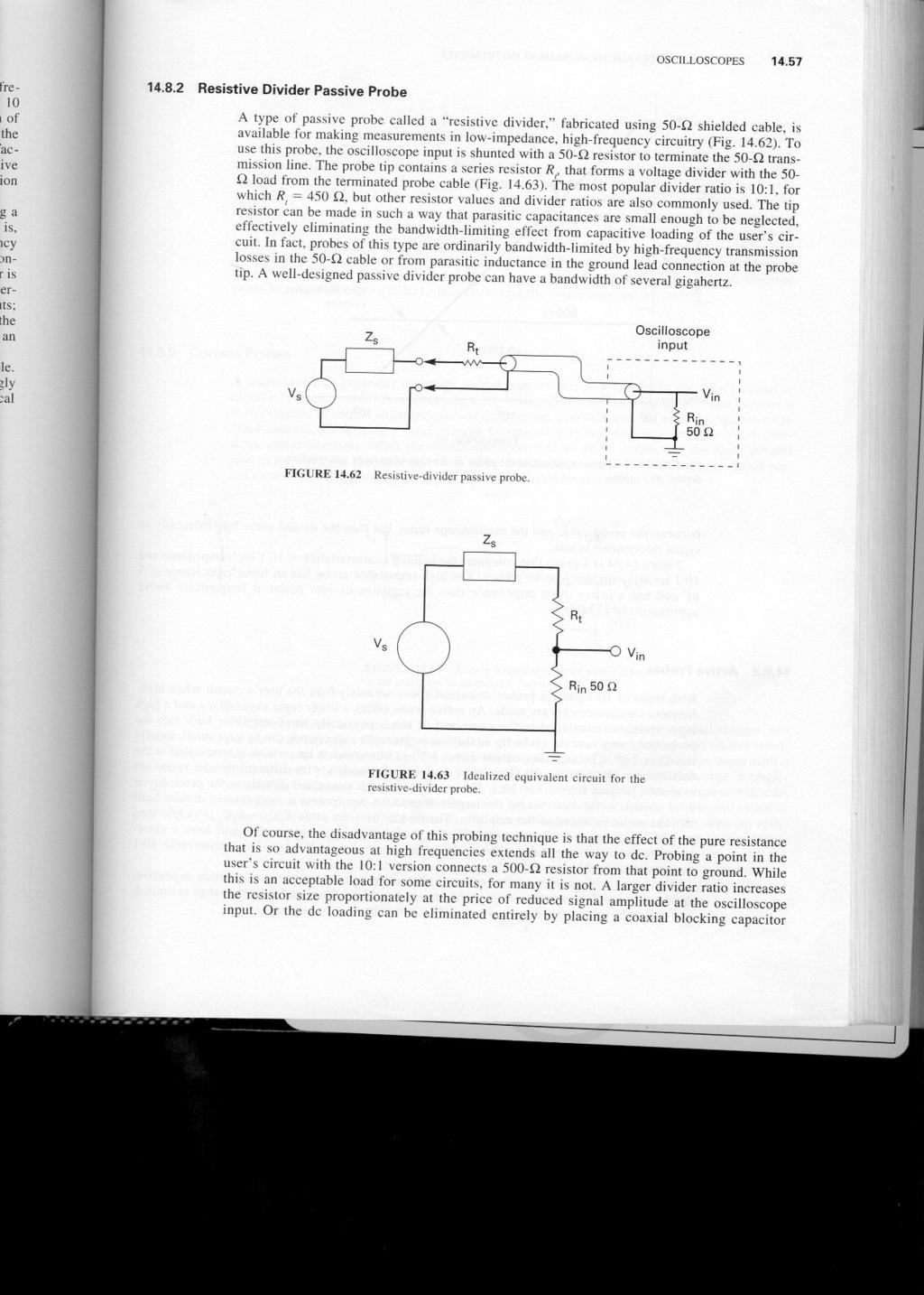
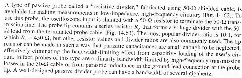
4 ~ OSCILLOSCOPES FIGURE Resistive-divider passive prore. Vs


5 14.58 CURRENT AND VOLTAGE MEASUREMENT INSTRUMENTS Diffl c: o) <J c: co "'C Q) a..~... ::J a. c: CUri Frequency, Hz FIGURE Input impedance at the probe tip for high-impedance and resisti vedivider 10:1 probes. between the probe cable and the oscillo scope input, but then the dc and some low-frequency ac signal information is lost. Figure is a graph that compares the loading characteristics of 10:1 high-impedance and 10:1 resistive-divider passive probes. The high-impedance probe has an input capacitance of 7 pf and has a lower input impedance than the resistive-divider probe at frequencies above approximately 45 MHz Active Probes Both types of 10:1 passive.probes discussed above seriously 10ad the user's circuit when highfrequency measurements afe made. An active probe offers a lower input capacitance and a high input resistance combined in the same unito It has a physically small amplifier built into the probe body very near the probe tip so that the probe input capacitance can be kept small, usual1y less than 2 pf. The amplifier output drives a 50-0 transmission line which is terminated at the oscilloscope input with a 50-0 resistor. Active probe models with different divider ratios afe available, ranging from I: 1 to 10: 1. The amplifier input is connected directly to the probe tip on al: 1 model, while units having the largest attenuation incorporate a compensated divider built into the probe tip ahead of the amplifier. The divider uses the same R1C1 = R2C2 principle used in 10: 1 high-impedance passive probes, so a model with larger attenuation will bave a correspondingly smaller input capacitance. Some active probe models provide a removable 10:1 compensated divider. Compared with passive probes, active probes afe generally larger, heavier, more expensive, and less rugged. Because the active probe uses an amplifier, the signal dynamic range is limited, and peaks above a certain amplitude, usually a few volts, will be clipped.


 the common mode signal, but inevitably there will be a small error response.")

6 OSCILLOSCOPES Differential Probes A "differenti al" probe is an active probe which has two inputs, ODe positive and ODe negative, and a separate ground lead, and it drives a single terminated 50-Q cable to transmit its output to ODe oscilloscope channel. The output signal is proportional to the difference between the voltages appearing at the two inputs. Both inputs can bave active signals simultaneously, but they must be within a few volts from ground to stay within the dynamic signal range of the probe. The average of the two input voltages is called the "common mode signal." A differential probe is designed to reject (not respond to) the common mode signal, but inevitably there will be a small error response. Common mode rejection capability is easily measured by connecting both inputs to the same signal simultaneously and observing the probe response. The rejection is best at dc and low frequencies and deteriorates with higher-frequency signals. Some active probe models provide a removable lo: l balanced two-input compensated divider. Tbe differenti al probe has disadvantages similar to those listed for the single-input active probe Current Probes A transducer that generates a voltage output proportional to a current in the user's circuit is called a "current probe." A resistor and a 1:1 voltage probe do that (Fig ) and they aie a usefu1 method in certain situations. However, inserting a resistor into the user's circuit has some disadvantages. Generating a large enough vo1tage drop to register adequate1y on the oscilloscope could adverse1y affect the circuit operation, and so might connecting the probe ground lead to the circuit at the point current is to be monitored. Using a differenti al probe would permit measuring current into or out of nodes which cannot be grounded FIGURE 14.6~ Adding a resister in series with a branch in Ihe user's circuìt uit to lo measure mea""e currenl "lirr..n' Current probes afe availabie that use a transforrner to, in effect, insert a small resistor into the user's circuit (Fig ). Located in the probe tip, a transforrner having a secondary winding of ns turns drives a 50-Q probe cabie which is terrninated at the oscilloscope input with a 50-Q resistor. The current to be measured in the user's circuit is conducted through a singieturo primary winding. Since it depends on a transforrner, this method does not measure dc currents; Le., it is ac-coupied. Using the equations for an ideai transformer, it is straightforward to show that (1) i = i In" (2) the sensitivity of the probe is R. In V/A, and (3) the apparent resistance in the prismary winding is Rjln/. When the transform~;' c~rrent probe is used to sense current in a wire in the user's circuit, a resistance R. In 2 appears to be added to that wire so that the Ioading effect of the current measurement can b~ d~termined. UnfortunateIy, probe manufacturers do not always state the number of turns on the transformer secondary winding explicitly, but the terrnination resistance and sensitivity afe given, and the number of secondary turns can be easily ca1cuiated.


7 14.60 CURRENT AND VOLTAGE MEASUREMENT INSTRUMENTS Current probes afe also available that lise "Hall effect" or a "Hall generator" to directly sense magnetic flux intensity in the transformer core to generate a voltage signal that is amplified and fed to an oscilloscope input. This method allows measurement of dc currents but is inherently limited to measuring relatively low frequency signals. Hybrid current probes combine a transformer and a Hall generator into an integrated unit and combine their outputs to provide the best features of both types. Measurement bandwidths from dc to approximately 50 MHz afe available. In one type of transformer current probe, a short length of wire is fed through a hole in the probe body, passing through the transformer core, and the wire is then inserted into the branch of the user's circuit to be measured. Other models arrange the transformer core material into two movable segments so that the transformer can be placed around an existing wire without first disconnecting it. The transformer turns ratio, and probe sensitivity, can be changed by looping two or more turns of the current-carrying wire through the transformer. Addition or subtraction of currents in different branches of the user's circuit can be performed by linking the curients through the current probe simultaneously, but there will be some cross-coupling between the branches measured HOW TO BUY AN OSCILLOSCOPE -' ',' "',.. In deciding whether to buy an oscilloscope or which model to buy, the first step is to careful1y define the measurement requirements it is to satisfy. Ask and answer questions lite these: What quantities need to be measured and to what accuracy? Where will it be used (laboratory, field service, etc.)? How long will the measurement requirement exist? Will the measurement requirement become more difficult? What is the technical skillievei of the operator(s)? What is the equipment purchase budget? What afe the probing requirements? As these questions afe addressed, other significant considerations or questions may be identified. Then a list of specifications that the oscillo scope must meet can be generated, perhaps with an additionallist of desirable features. The next step is to identify and evaluate the oscillo scope models that could potentially satisfy the measurement requirements. Contact the various oscilloscope manufacturers' sales repre-
How to Select the Right Current Probe APPLICATION NOTE
 How to Select the Right Current Probe APPLICATION NOTE Overview Oscilloscope current probes enable oscilloscopes to measure current, extending their use beyond just measuring voltage. Basically, current
Filters And Waveform Shaping
 Physics 3330 Experiment #3 Fall 2001 Purpose Filters And Waveform Shaping The aim of this experiment is to study the frequency filtering properties of passive (R, C, and L) circuits for sine waves, and
ECE 2274 Lab 2. Your calculator will have a setting that will automatically generate the correct format.
 ECE 2274 Lab 2 Forward (DO NOT TURN IN) You are expected to use engineering exponents for all answers (p,n,µ,m, N/A, k, M, G) and to give each with a precision between one and three leading digits and
ECE 2274 Lab 2 (Network Theorems)
") ECE 2274 Lab 2 (Network Theorems) Forward (DO NOT TURN IN) You are expected to use engineering exponents for all answers (p,n,µ,m, N/A, k, M, G) and to give each with a precision between one and three
ECE 2274 Lab 2 (Network Theorems) Forward (DO NOT TURN IN) You are expected to use engineering exponents for all answers (p,n,µ,m, N/A, k, M, G) and to give each with a precision between one and three
Probe Considerations for Low Voltage Measurements such as Ripple
 Probe Considerations for Low Voltage Measurements such as Ripple Our thanks to Tektronix for allowing us to reprint the following article. Figure 1. 2X Probe (CH1) and 10X Probe (CH2) Lowest System Vertical
Group: Names: (1) In this step you will examine the effects of AC coupling of an oscilloscope.
 In this step you will examine the effects of AC coupling of an oscilloscope.") 3.5 Laboratory Procedure / Summary Sheet Group: Names: (1) In this step you will examine the effects of AC coupling of an oscilloscope. Set the function generator to produce a 5 V pp 1kHz sinusoidal output.
3.5 Laboratory Procedure / Summary Sheet Group: Names: (1) In this step you will examine the effects of AC coupling of an oscilloscope. Set the function generator to produce a 5 V pp 1kHz sinusoidal output.
AIM & THURLBY THANDAR INSTRUMENTS
 AIM & THURLBY THANDAR INSTRUMENTS I-prober 520 positional current probe Unique technology enabling current measurement in PCB tracks bandwidth of DC to 5MHz, dynamic range of 10mA to 20A pk-pk useable
AN-671 APPLICATION NOTE One Technology Way P.O. Box 9106 Norwood, MA Tel: 781/ Fax: 781/
 APPLICATION NOTE One Technology Way P.O. Box 910 Norwood, MA 0202-910 Tel: 781/329-4700 Fax: 781/32-8703 www.analog.com Reducing RFI Rectification Errors in In-Amp Circuits By Charles Kitchin, Lew Counts,
 1 of 6 03/12/2012 14:56 2012-12-03 HAMEG > Products > Accessories > Probes http://www.hameg.com/186.0.html P R O B E S H Z 5 6-2 * AC/ DC Current Clamps This AC/DC Current Probe is used to measure currents
Document Name: Electronic Circuits Lab. Facebook: Twitter:
 Document Name: Electronic Circuits Lab www.vidyathiplus.in Facebook: www.facebook.com/vidyarthiplus Twitter: www.twitter.com/vidyarthiplus Copyright 2011-2015 Vidyarthiplus.in (VP Group) Page 1 CIRCUIT
B. Equipment. Advanced Lab
 Advanced Lab Measuring Periodic Signals Using a Digital Oscilloscope A. Introduction and Background We will use a digital oscilloscope to characterize several different periodic voltage signals. We will
CONNECTING THE PROBE TO THE TEST INSTRUMENT
 2SHUDWLRQ 2SHUDWLRQ Caution The input circuits in the AP034 Active Differential Probe incorporate components that protect the probe from damage resulting from electrostatic discharge (ESD). Keep in mind
Effectively Using the EM 6992 Near Field Probe Kit to Troubleshoot EMI Issues
 Effectively Using the EM 6992 Near Field Probe Kit to Troubleshoot EMI Issues Introduction The EM 6992 Probe Kit includes three magnetic (H) field and two electric (E) field passive, near field probes
Probing for oscilloscope
 Probing for oscilloscope Agenda - Notion de sonde en oscilloscopie - Structure des différentes sondes - Passives - Actives - Logiques - Différentielles - Comment choisir la bonne sonde - Nouvelle technologie
Agilent E2695A SMA Probe Head for InfiniiMax 1130 Series Active Oscilloscope Probes. User s Guide
 User s Guide Publication Number E2695-92000 June 2003 Copyright Agilent Technologies 2003 All Rights Reserved. Agilent E2695A SMA Probe Head for InfiniiMax 1130 Series Active Oscilloscope Probes Agilent
LFR: flexible, clip-around current probe for use in power measurements
 LFR: flexible, clip-around current probe for use in power measurements These technical notes should be read in conjunction with the LFR short-form datasheet. Power Electronic Measurements Ltd Nottingham
Differential Amplifier : input. resistance. Differential amplifiers are widely used in engineering instrumentation
 Differential Amplifier : input resistance Differential amplifiers are widely used in engineering instrumentation Differential Amplifier : input resistance v 2 v 1 ir 1 ir 1 2iR 1 R in v 2 i v 1 2R 1 Differential
AIM & THURLBY THANDAR INSTRUMENTS
 AIM & THURLBY THANDAR INSTRUMENTS I-prober 520 positional current probe Unique technology enabling current measurement in PCB tracks bandwidth of DC to 5MHz, dynamic range of 10mA to 20A pk-pk useable
Measurement and Analysis for Switchmode Power Design
 Measurement and Analysis for Switchmode Power Design Switched Mode Power Supply Measurements AC Input Power measurements Safe operating area Harmonics and compliance Efficiency Switching Transistor Losses
ET1210: Module 5 Inductance and Resonance
 Part 1 Inductors Theory: When current flows through a coil of wire, a magnetic field is created around the wire. This electromagnetic field accompanies any moving electric charge and is proportional to
Op-Amp Simulation Part II
 Op-Amp Simulation Part II EE/CS 5720/6720 This assignment continues the simulation and characterization of a simple operational amplifier. Turn in a copy of this assignment with answers in the appropriate
Signal Conditioning Devices
 Lecture 4. Signal Conditioning Devices Signal Conditioning Operations In previous lectures we have studied various sensors and transducers used in a mechatronics system. Transducers sense physical phenomenon
ECE3204 D2015 Lab 1. See suggested breadboard configuration on following page!
 ECE3204 D2015 Lab 1 The Operational Amplifier: Inverting and Non-inverting Gain Configurations Gain-Bandwidth Product Relationship Frequency Response Limitation Transfer Function Measurement DC Errors
TAKE THE MYSTERY OUT OF PROBING. 7 Common Oscilloscope Probing Pitfalls to Avoid
 TAKE THE MYSTERY OUT OF PROBING 7 Common Oscilloscope Probing Pitfalls to Avoid Introduction Understanding common probing pitfalls and how to avoid them is crucial in making better measurements. In an
Section 6 - Electronics
 Section 6 - Electronics 6.1. Power for Excitation Piezoresistive transducers are passive devices and require an external power supply to provide the necessary current (I x ) or voltage excitation (E x
Multi-function Gain-Phase Analyzer (Frequency Response Analyzer) Model 2505
 Model 2505") OTHER PRODUCTS.. Multi-function Gain-Phase Analyzer ( Response Analyzer) Model 2505 Standard Configurations Gain phase analyzer response analyzer Phase Angle Voltmeter (PAV) Fast dual channel wide-band
OTHER PRODUCTS.. Multi-function Gain-Phase Analyzer ( Response Analyzer) Model 2505 Standard Configurations Gain phase analyzer response analyzer Phase Angle Voltmeter (PAV) Fast dual channel wide-band
PHV RO. High impedance passive probe. Features: CeramCore TM Hybrid Probe. Modular Construction. Coaxial Design
 High impedance passive probe Features: CeramCore TM Hybrid Probe Modular Construction Coaxial Design Interchangeable Spring Contact Tip Certificate of Calibration available on request Read-out BNC Connector
ENG 100 Lab #2 Passive First-Order Filter Circuits
 ENG 100 Lab #2 Passive First-Order Filter Circuits In Lab #2, you will construct simple 1 st -order RL and RC filter circuits and investigate their frequency responses (amplitude and phase responses).
Laboratory 3 (drawn from lab text by Alciatore)
") Laboratory 3 (drawn from lab text by Alciatore) The Oscilloscope Required Components: 1 10 resistor 2 100 resistors 2 lk resistors 1 2k resistor 2 4.7M resistors 1 0.F capacitor 1 0.1 F capacitor 1 1.0uF
Laboratory 3 (drawn from lab text by Alciatore) The Oscilloscope Required Components: 1 10 resistor 2 100 resistors 2 lk resistors 1 2k resistor 2 4.7M resistors 1 0.F capacitor 1 0.1 F capacitor 1 1.0uF
Active: Active probes achieve low input capacitance and high sensitivity by buffering and amplifying the signal close to the point of measurement.
 Application Note Pico Technology offers many s covering a wide range of voltages, category (CAT) ratings and bandwidths. As the name suggests, these probes have two major features: Active: Active probes
EIE 015 Power Electronics (2009) Laboratory exercise 3. Active Filter Control
 Laboratory exercise 3. Active Filter Control") EIE 015 Power Electronics (2009) Laboratory exercise 3 Active Filter Control igrid cp iload ifilter Control of Electrical Drives. Laboratory exercise 2 2 1. Introduction In this lab a Shunt Active Filter
EIE 015 Power Electronics (2009) Laboratory exercise 3 Active Filter Control igrid cp iload ifilter Control of Electrical Drives. Laboratory exercise 2 2 1. Introduction In this lab a Shunt Active Filter
Transmit filter designs for ADSL modems
 EE 233 Laboratory-4 1. Objectives Transmit filter designs for ADSL modems Design a filter from a given topology and specifications. Analyze the characteristics of the designed filter. Use SPICE to verify
UNIT 1 CIRCUIT ANALYSIS 1 What is a graph of a network? When all the elements in a network is replaced by lines with circles or dots at both ends.
 UNIT 1 CIRCUIT ANALYSIS 1 What is a graph of a network? When all the elements in a network is replaced by lines with circles or dots at both ends. 2 What is tree of a network? It is an interconnected open
Table of Contents...2. About the Tutorial...6. Audience...6. Prerequisites...6. Copyright & Disclaimer EMI INTRODUCTION Voltmeter...
 1 Table of Contents Table of Contents...2 About the Tutorial...6 Audience...6 Prerequisites...6 Copyright & Disclaimer...6 1. EMI INTRODUCTION... 7 Voltmeter...7 Ammeter...8 Ohmmeter...8 Multimeter...9
PowerAmp Design. PowerAmp Design PAD112 HIGH VOLTAGE OPERATIONAL AMPLIFIER
 PowerAmp Design Rev C KEY FEATURES LOW COST HIGH VOLTAGE 150 VOLTS HIGH OUTPUT CURRENT 5 AMPS 50 WATT DISSIPATION CAPABILITY 100 WATT OUTPUT CAPABILITY INTEGRATED HEAT SINK AND FAN COMPATIBLE WITH PAD123
EK307 Active Filters and Steady State Frequency Response
 EK307 Active Filters and Steady State Frequency Response Laboratory Goal: To explore the properties of active signal-processing filters Learning Objectives: Active Filters, Op-Amp Filters, Bode plots Suggested
Application Note SAW-Components
 Application Note SAW-Components Comparison between negative impedance oscillator (Colpitz oscillator) and feedback oscillator (Pierce structure) App.: Note #13 Author: Alexander Glas EPCOS AG Updated:
Transformer Waveforms
 OBJECTIVE EXPERIMENT Transformer Waveforms Steady-State Testing and Performance of Single-Phase Transformers Waveforms The voltage regulation and efficiency of a distribution system are affected by the
Testing and Stabilizing Feedback Loops in Today s Power Supplies
 Keywords Venable, frequency response analyzer, impedance, injection transformer, oscillator, feedback loop, Bode Plot, power supply design, open loop transfer function, voltage loop gain, error amplifier,
Experiment 1: Instrument Familiarization (8/28/06)
") Electrical Measurement Issues Experiment 1: Instrument Familiarization (8/28/06) Electrical measurements are only as meaningful as the quality of the measurement techniques and the instrumentation applied
Electrical Measurement Issues Experiment 1: Instrument Familiarization (8/28/06) Electrical measurements are only as meaningful as the quality of the measurement techniques and the instrumentation applied
11. AC-resistances of capacitor and inductors: Reactances.
 11. AC-resistances of capacitor and inductors: Reactances. Purpose: To study the behavior of the AC voltage signals across elements in a simple series connection of a resistor with an inductor and with
The Ins and Outs of Audio Transformers. How to Choose them and How to Use them
 The Ins and Outs of Audio Transformers How to Choose them and How to Use them Steve Hogan Product Development Engineer, Jensen Transformers 1983 1989 Designed new products and provided application assistance
MIL-STD-883E METHOD 3024 SIMULTANEOUS SWITCHING NOISE MEASUREMENTS FOR DIGITAL MICROELECTRONIC DEVICES
 SIMULTANEOUS SWITCHING NOISE MEASUREMENTS FOR DIGITAL MICROELECTRONIC DEVICES 1. Purpose. This method establishes the procedure for measuring the ground bounce (and V CC bounce) noise in digital microelectronic
PowerAmp Design. PowerAmp Design PAD117A RAIL TO RAIL OPERATIONAL AMPLIFIER
 PowerAmp Design RAIL TO RAIL OPERATIONAL AMPLIFIER Rev J KEY FEATURES LOW COST RAIL TO RAIL INPUT & OUTPUT SINGLE SUPPLY OPERATION HIGH VOLTAGE 100 VOLTS HIGH OUTPUT CURRENT 15A 250 WATT OUTPUT CAPABILITY
Supplied in carry case with additional accessories The PHV 1000-RO is a 400 MHz, standard sized, 100:1 passive probe designed for instruments
 High impedance passive probe Features: CeramCore TM hybrid probe Modular construction Coaxial design Interchangeable spring contact tip Certificate of calibration available on request Read-out BNC connector
AN-742 APPLICATION NOTE One Technology Way P.O. Box 9106 Norwood, MA Tel: 781/ Fax: 781/
 APPLICATION NOTE One Technology Way P.O. Box 9106 Norwood, MA 02062-9106 Tel: 781/329-4700 Fax: 781/461-3113 www.analog.com Frequency Domain Response of Switched-Capacitor ADCs by Rob Reeder INTRODUCTION
Experiment 1: Instrument Familiarization
 Electrical Measurement Issues Experiment 1: Instrument Familiarization Electrical measurements are only as meaningful as the quality of the measurement techniques and the instrumentation applied to the
V.S.B ENGINEERING COLLEGE DEPARTMENT OF ELECTRICAL AND ELECTRONICS ENGINEERING I EEE-II Semester all subjects 2 & 16 marks QB
 V.S.B ENGINEERING COLLEGE DEPARTMENT OF ELECTRICAL AND ELECTRONICS ENGINEERING I EEE-II Semester all subjects 2 & 16 marks QB Sl.No Subject Name Page No. 1 Circuit Theory 2 1 UNIT-I CIRCUIT THEORY TWO
Department of Electrical & Computer Engineering Technology. EET 3086C Circuit Analysis Laboratory Experiments. Masood Ejaz
 Department of Electrical & Computer Engineering Technology EET 3086C Circuit Analysis Laboratory Experiments Masood Ejaz Experiment # 1 DC Measurements of a Resistive Circuit and Proof of Thevenin Theorem
UNIT 2. Q.1) Describe the functioning of standard signal generator. Ans. Electronic Measurements & Instrumentation
 Describe the functioning of standard signal generator. Ans. Electronic Measurements & Instrumentation") UNIT 2 Q.1) Describe the functioning of standard signal generator Ans. STANDARD SIGNAL GENERATOR A standard signal generator produces known and controllable voltages. It is used as power source for the
UNIT 2 Q.1) Describe the functioning of standard signal generator Ans. STANDARD SIGNAL GENERATOR A standard signal generator produces known and controllable voltages. It is used as power source for the
Experiment 45. Three-Phase Circuits. G 1. a. Using your Power Supply and AC Voltmeter connect the circuit shown OBJECTIVE
 Experiment 45 Three-Phase Circuits OBJECTIVE To study the relationship between voltage and current in three-phase circuits. To learn how to make delta and wye connections. To calculate the power in three-phase
EXPERIMENT 4: RC, RL and RD CIRCUITs
 EXPERIMENT 4: RC, RL and RD CIRCUITs Equipment List Resistor, one each of o 330 o 1k o 1.5k o 10k o 100k o 1000k 0.F Ceramic Capacitor 4700H Inductor LED and 1N4004 Diode. Introduction We have studied
EK307 Passive Filters and Steady State Frequency Response
 EK307 Passive Filters and Steady State Frequency Response Laboratory Goal: To explore the properties of passive signal-processing filters Learning Objectives: Passive filters, Frequency domain, Bode plots
Lab 3 Transient Response of RC & RL Circuits
 Lab 3 Transient Response of RC & RL Circuits Last Name: First Name: Student Number: Lab Section: Monday Tuesday Wednesday Thursday Friday TA Signature: Note: The Pre-Lab section must be completed prior
EE 241 Experiment #4: USE OF BASIC ELECTRONIC MEASURING INSTRUMENTS, Part III 1
 EE 241 Experiment #4: USE OF BASIC ELECTRONIC MEASURING INSTRUMENTS, Part III 1 PURPOSE: To become familiar with more of the instruments in the laboratory. To become aware of operating limitations of input
Contents. Core information about Unit
 1 Contents Core information about Unit UEENEEH114A - Troubleshoot resonance circuits......3 UEENEEG102A Solve problems in low voltage AC circuits...5 TextBook...7 Topics and material Week 1...9 2 Core
LM13600 Dual Operational Transconductance Amplifiers with Linearizing Diodes and Buffers
 LM13600 Dual Operational Transconductance Amplifiers with Linearizing Diodes and Buffers General Description The LM13600 series consists of two current controlled transconductance amplifiers each with
OPERATIONAL AMPLIFIERS (OP-AMPS) II
 II") OPERATIONAL AMPLIFIERS (OP-AMPS) II LAB 5 INTRO: INTRODUCTION TO INVERTING AMPLIFIERS AND OTHER OP-AMP CIRCUITS GOALS In this lab, you will characterize the gain and frequency dependence of inverting op-amp
OPERATIONAL AMPLIFIERS (OP-AMPS) II LAB 5 INTRO: INTRODUCTION TO INVERTING AMPLIFIERS AND OTHER OP-AMP CIRCUITS GOALS In this lab, you will characterize the gain and frequency dependence of inverting op-amp
PMT 211A-RO. High impedance passive probe. Features: CeramCore TM Hybrid Probe. Modular Construction. Coaxial Design
 High impedance passive probe Features: CeramCore TM Hybrid Probe Modular Construction Coaxial Design Interchangeable Spring Contact Tip IC Contacting System 0.8 to 1.27 mm pitch The PMT 211A-RO is a 250
KINGS COLLEGE OF ENGINEERING DEPARTMENT OF ELECTRICAL AND ELECTRONICS ENGINEERING QUESTION BANK UNIT I BASIC CIRCUITS ANALYSIS PART A (2-MARKS)
") KINGS COLLEGE OF ENGINEERING DEPARTMENT OF ELECTRICAL AND ELECTRONICS ENGINEERING QUESTION BANK YEAR / SEM : I / II SUBJECT CODE & NAME : EE 1151 CIRCUIT THEORY UNIT I BASIC CIRCUITS ANALYSIS PART A (2-MARKS)
KINGS COLLEGE OF ENGINEERING DEPARTMENT OF ELECTRICAL AND ELECTRONICS ENGINEERING QUESTION BANK YEAR / SEM : I / II SUBJECT CODE & NAME : EE 1151 CIRCUIT THEORY UNIT I BASIC CIRCUITS ANALYSIS PART A (2-MARKS)
Design and Simulation of Passive Filter
 Chapter 3 Design and Simulation of Passive Filter 3.1 Introduction Passive LC filters are conventionally used to suppress the harmonic distortion in power system. In general they consist of various shunt
Instrumentation amplifier
 Instrumentationamplifieris a closed-loop gainblock that has a differential input and an output that is single-ended with respect to a reference terminal. Application: are intended to be used whenever acquisition
Integrators, differentiators, and simple filters
 BEE 233 Laboratory-4 Integrators, differentiators, and simple filters 1. Objectives Analyze and measure characteristics of circuits built with opamps. Design and test circuits with opamps. Plot gain vs.
DC MHZ PXI Differential Instrumentation Amplifier
 DC - 100 MHZ PXI Differential Instrumentation Amplifier Differential 100 V Common Mode Input DC - 100 MHz Bandwidth AC/DC Coupling Programmable Attenuation/Gain/ Offset 9 nv/ Input Noise 50 Ω Output Impedance
PowerAmp Design. PowerAmp Design PAD20 COMPACT HIGH VOLTAGE OP AMP
 PowerAmp Design Rev C KEY FEATURES LOW COST HIGH VOLTAGE 150 VOLTS HIGH OUTPUT CURRENT 5A 40 WATT DISSIPATION CAPABILITY 80 WATT OUTPUT CAPABILITY INTEGRATED HEAT SINK AND FAN SMALL SIZE 40mm SQUARE RoHS
DESIGN OF A FULLY DIFFERENTIAL HIGH-SPEED HIGH-PRECISION AMPLIFIER
 DESIGN OF A FULLY DIFFERENTIAL HIGH-SPEED HIGH-PRECISION AMPLIFIER Mayank Gupta mayank@ee.ucla.edu N. V. Girish envy@ee.ucla.edu Design I. Design II. University of California, Los Angeles EE215A Term Project
QUESTION BANK ETE (17331) CM/IF. Chapter1: DC Circuits
 CM/IF. Chapter1: DC Circuits") QUESTION BANK ETE (17331) CM/IF Chapter1: DC Circuits Q1. State & explain Ohms law. Also explain concept of series & parallel circuit with the help of diagram. 3M Q2. Find the value of resistor in fig.
QUESTION BANK ETE (17331) CM/IF Chapter1: DC Circuits Q1. State & explain Ohms law. Also explain concept of series & parallel circuit with the help of diagram. 3M Q2. Find the value of resistor in fig.
Group: Names: Resistor Band Colors Measured Value ( ) R 1 : 1k R 2 : 1k R 3 : 2k R 4 : 1M R 5 : 1M
 R 1 : 1k R 2 : 1k R 3 : 2k R 4 : 1M R 5 : 1M") 2.4 Laboratory Procedure / Summary Sheet Group: Names: (1) Select five separate resistors whose nominal values are listed below. Record the band colors for each resistor in the table below. Then connect
2.4 Laboratory Procedure / Summary Sheet Group: Names: (1) Select five separate resistors whose nominal values are listed below. Record the band colors for each resistor in the table below. Then connect
VETRI VINAYAHA COLLEGE OF ENGINEERING AND TECHNOLOGY
 VETRI VINAYAHA COLLEGE OF ENGINEERING AND TECHNOLOGY DEPARTMENT OF ELECTRICAL AND ELECTRONICS ENGINEERING I-YEAR/II-SEMESTER- EEE&ECE EE6201- CIRCUIT THEORY Two Marks with Answers PREPARED BY: Mr.A.Thirukkumaran,
EXPERIMENT 8: LRC CIRCUITS
 EXPERIMENT 8: LRC CIRCUITS Equipment List S 1 BK Precision 4011 or 4011A 5 MHz Function Generator OS BK 2120B Dual Channel Oscilloscope V 1 BK 388B Multimeter L 1 Leeds & Northrup #1532 100 mh Inductor
Chapter 7. Response of First-Order RL and RC Circuits
 Chapter 7. Response of First-Order RL and RC Circuits By: FARHAD FARADJI, Ph.D. Assistant Professor, Electrical Engineering, K.N. Toosi University of Technology http://wp.kntu.ac.ir/faradji/electriccircuits1.htm
Choosing the right Pico Technology active differential probe
 Pico Technology offers many active s covering a wide range of voltages, category (CAT) ratings and bandwidths. As the name suggests, these probes have two major features: Active: Active probes achieve
Keysight Technologies How to Select the Right Current Probe. Application Note
 Keysight Technologies How to Select the Right Current Probe Application Note 02 Keysight How to Select the Right Current Probe - Application Note Overview Oscilloscope current probes enable oscilloscopes
PART TOP VIEW V EE 1 V CC 1 CONTROL LOGIC
 19-1331; Rev 1; 6/98 EVALUATION KIT AVAILABLE Upstream CATV Driver Amplifier General Description The MAX3532 is a programmable power amplifier for use in upstream cable applications. The device outputs
Voltage Probe Manual and Data North Star High Voltage, Inc. Rev January 2016
 561 Rose Loop NE Bainbridge Island, WA, USA 9811 (52)78-93; (26)219-425 FAX http://www.highvoltageprobes.com probes@highvoltageprobes.com Voltage Probe Manual and Data North Star High Voltage, Inc. Rev
ActiveLowPassFilter -- Overview
 ActiveLowPassFilter -- Overview OBJECTIVES: At the end of performing this experiment, learners would be able to: Describe the concept of active Low Pass Butterworth Filter Obtain the roll-off factor and
Power. Power is the rate of using energy in joules per second 1 joule per second Is 1 Watt
 3 phase Power All we need electricity for is as a source of transport for energy. We can connect to a battery, which is a source of stored energy. Or we can plug into and electric socket at home or in
PURPOSE: NOTE: Be sure to record ALL results in your laboratory notebook.
 EE4902 Lab 9 CMOS OP-AMP PURPOSE: The purpose of this lab is to measure the closed-loop performance of an op-amp designed from individual MOSFETs. This op-amp, shown in Fig. 9-1, combines all of the major
University of Jordan School of Engineering Electrical Engineering Department. EE 219 Electrical Circuits Lab
 University of Jordan School of Engineering Electrical Engineering Department EE 219 Electrical Circuits Lab EXPERIMENT 4 TRANSIENT ANALYSIS Prepared by: Dr. Mohammed Hawa EXPERIMENT 4 TRANSIENT ANALYSIS
Chapter 9. Evaluation and Measurement
 Chapter 9 Evaluation and Measurement CONTENTS Page 1 Application scope 9-1 2 Evaluation and measurement methods 9-2 This section explains the method of evaluating the IGBT module characteristics and the
EXAM Amplifiers and Instrumentation (EE1C31)
") DELFT UNIVERSITY OF TECHNOLOGY Faculty of Electrical Engineering, Mathematics and Computer Science EXAM Amplifiers and Instrumentation (EE1C31) April 18, 2017, 9.00-12.00 hr This exam consists of four
DELFT UNIVERSITY OF TECHNOLOGY Faculty of Electrical Engineering, Mathematics and Computer Science EXAM Amplifiers and Instrumentation (EE1C31) April 18, 2017, 9.00-12.00 hr This exam consists of four
EET 438a Automatic Control Systems Technology Laboratory 1 Analog Sensor Signal Conditioning
 EET 438a Automatic Control Systems Technology Laboratory 1 Analog Sensor Signal Conditioning Objectives: Use analog OP AMP circuits to scale the output of a sensor to signal levels commonly found in practical
Lab E2: B-field of a Solenoid. In the case that the B-field is uniform and perpendicular to the area, (1) reduces to
 reduces to") E2.1 Lab E2: B-field of a Solenoid In this lab, we will explore the magnetic field created by a solenoid. First, we must review some basic electromagnetic theory. The magnetic flux over some area A is
E2.1 Lab E2: B-field of a Solenoid In this lab, we will explore the magnetic field created by a solenoid. First, we must review some basic electromagnetic theory. The magnetic flux over some area A is
Oscilloscope Fundamentals. For Electrical Engineering and Physics Undergraduate Students
 Oscilloscope Fundamentals For Electrical Engineering and Physics Undergraduate Students Agenda What is an oscilloscope? Probing basics (low-frequency model) Making voltage and timing measurements Properly
LABORATORY 4. Palomar College ENGR210 Spring 2017 ASSIGNED: 3/21/17
 LABORATORY 4 ASSIGNED: 3/21/17 OBJECTIVE: The purpose of this lab is to evaluate the transient and steady-state circuit response of first order and second order circuits. MINIMUM EQUIPMENT LIST: You will
Model 7000 Low Noise Differential Preamplifier
 Model 7000 Low Noise Differential Preamplifier Operating Manual Service and Warranty Krohn-Hite Instruments are designed and manufactured in accordance with sound engineering practices and should give
While the Riso circuit is both simple to implement and design it has a big disadvantage in precision circuits. The voltage drop from Riso is
 Hello, and welcome to part six of the TI Precision Labs on op amp stability. This lecture will describe the Riso with dual feedback stability compensation method. From 5: The previous videos discussed
Application Note 5525
 Using the Wafer Scale Packaged Detector in 2 to 6 GHz Applications Application Note 5525 Introduction The is a broadband directional coupler with integrated temperature compensated detector designed for
RF300 LARGE LOOP ANTENNA
 LAPLACE INSTRUMENTS LTD RF300 LARGE LOOP ANTENNA USER GUIDE Serial Number 9072 Issue 5 May 2010 Page 1 INDEX Introduction 3 Packing list 3 Assembly 5 Calibration loop 12 Calibration 13 Operation 14 In
PowerAmp Design. PowerAmp Design PAD196 HIGH VOLATGE OPERATIONAL AMPLIFIER
 PowerAmp Design HIGH VOLTAGE OPERATIONAL AMPLIFIER Preliminary Information Rev D KEY FEATURES LOW COST SMALL SIZE 50mm SQUARE HIGH VOLTAGE 2050 VOLTS OUTPUT CURRENT 50mA 12 WATT DISSIPATION CAPABILITY
Transmit filter designs for ADSL modems
 Transmit filter designs for ADSL modems 1. OBJECTIVES... 2 2. REFERENCE... 2 3. CIRCUITS... 2 4. COMPONENTS AND SPECIFICATIONS... 3 5. DISCUSSION... 3 6. PRE-LAB... 4 6.1 RECORDING SPECIFIED OPAMP PARAMETERS
Exp 3 COLCULATE THE RESPONSE TIME FOR THE SILICON DETECTOR
 Exp 3 اعداد المدرس مكرم عبد المطلب فخري Object: To find the value of the response time (Tr) for silicone photodiode detector. Equipment: 1- function generator ( 10 khz ). 2- silicon detector. 3- storage
Characteristics of Crystal. Piezoelectric effect of Quartz Crystal
 Characteristics of Crystal Piezoelectric effect of Quartz Crystal The quartz crystal has a character when the pressure is applied to the direction of the crystal axis, the electric change generates on
X2Y Capacitors for Instrumentation Amplifier RFI Suppression
 XY Capacitors for Instrumentation mplifier Summary Instrumentation amplifiers are often employed in hostile environments. Long sensor lead cables may pick-up substantial RF radiation, particularly if they
LECTURE 2: PD, PID, and Feedback Compensation. ( ) = + We consider various settings for Zc when compensating the system with the following RL:
 = + We consider various settings for Zc when compensating the system with the following RL:") LECTURE 2: PD, PID, and Feedback Compensation. 2.1 Ideal Derivative Compensation (PD) Generally, we want to speed up the transient response (decrease Ts and Tp). If we are lucky then a system s desired
LECTURE 2: PD, PID, and Feedback Compensation. 2.1 Ideal Derivative Compensation (PD) Generally, we want to speed up the transient response (decrease Ts and Tp). If we are lucky then a system s desired
Probing Techniques for Signal Performance Measurements in High Data Rate Testing
 Probing Techniques for Signal Performance Measurements in High Data Rate Testing K. Helmreich, A. Lechner Advantest Test Engineering Solutions GmbH Contents: 1 Introduction: High Data Rate Testing 2 Signal
Part VI: Requirements for ISDN Terminal Equipment
 Issue 9 November 2004 Spectrum Management and Telecommunications Policy Compliance Specification for Terminal Equipment, Terminal Systems, Network Protection Devices, Connection Arrangements and Hearing
CHAPTER 2 D-Q AXES FLUX MEASUREMENT IN SYNCHRONOUS MACHINES
 22 CHAPTER 2 D-Q AXES FLUX MEASUREMENT IN SYNCHRONOUS MACHINES 2.1 INTRODUCTION For the accurate analysis of synchronous machines using the two axis frame models, the d-axis and q-axis magnetic characteristics
PMT 221A. High impedance passive probe. Features: CeramCore TM Hybrid Probe. Modular Construction. Coaxial Design. Interchangeable Spring Contact Tip
 High impedance passive probe Features: CeramCore TM Hybrid Probe Modular Construction Coaxial Design Interchangeable Spring Contact Tip IC Contacting System 0.8 to 1.27 mm pitch Unbreakable Reed Switch
SENSOR AND MEASUREMENT EXPERIMENTS
 SENSOR AND MEASUREMENT EXPERIMENTS Page: 1 Contents 1. Capacitive sensors 2. Temperature measurements 3. Signal processing and data analysis using LabVIEW 4. Load measurements 5. Noise and noise reduction