GSM/GPRS Module DIY Kit
|
|
|
- Marcia Summers
- 6 years ago
- Views:
Transcription

1 GSM/GPRS Module DIY Kit This instructable is about an extremely cheap GSM/GPRS module which comes as a do it yourself kit. We are going to assemble the parts and do some basic operations through software terminal. Finally we send out SMS messages. This is the first article of a serie. Later ibles will discuss: Controlling the GSM module by a PIC microcontroller (and maybe by arduino). Update: click here to read the PIC controlled SMS sending instructable. Connecting sensors to the microcontroller to send SMS alerts when the sensors are triggered. Sensors can be PIR detectors, ultrasonic sensors, or door opening detectors.

2 One step beyond sending SMS: using the GSM/GPRS modul data transmission features to send data to a web server using POST method. One step further: sending data through FTP protocol. More triggers: using multiplexer to get up to 16 event source with only 3 pins of the microcontroller. Further ibles will born as I develop my automated off-site security and yard-automation system. Step 1: Neoway M590E GSM/GPRS Module I was looking for the cheapest solution to give mobile communication features to my home automation hobby project. M590E is surprisingly underpriced: the time of writing this ible one can buy full GSM and GPRS functionality for less than 2 GBP. That's about 3 USD. Wow! What we get for this price is impressive: ultra compact (28 x 22 mm) GSM/GPRS industrial wireless module support for both 900MHz and 1800MHz GSM frequencies standard AT instruction set (a very easy way to command&control the modem)
 accomodate any SIM card size (with a card adapter) Well why this module is sooo cheap, you may ask. Not sure.")
3 integrated support of TCP/IP, http GET/POST, FTP and UDP data transfer protocols low energy consumption (measured virtually zero wattage with 3.2 ma at 3.9 V, and 180 ma peaks during SMS sending) accomodate any SIM card size (with a card adapter) Well why this module is sooo cheap, you may ask. Not sure... but this is a 2G device and as 5G is coming these modems will be obsolate within a few years. But until that let's get good use of it! ;-) Step 2: The Modified DIY Kit
4

5 Show All 8 Items M590E is the module itself and the PCB is an independent product. You required to solder a few surface-mounted parts to the board, and the GSM modul itself of course.
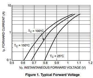
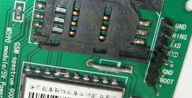
6 You can realtively easily assemble the kit and get it working. There are a few blog posts on the internet illustrating that this kit can be used as it is. However if you read the manufacturer's specification for M590E you can recognise some design flaws of the DIY kit. These are obviously there to get the kit as cheap as possible and to simplify the process of assembling the board by hobbyists equipped with only a common soldering iron. So the design is all right and all my modifications to fit it to M590E hardware specification is optional. First of all you need a good power source to feed the modem as it may suck as much as 2 ampers while transmitting. Many wall adapters are unable to provide this amount of current. If the power source is weak the modem will not boot up at all or repeatedly rebooting, or just fail to communicate. Next, the modem can be operated within the 3.3V - 4.5V range. The recommended voltage is 3.9V. The kit is designed to be used with 5V (probably because arduino also works on 5V). So the DIY kit includes a 1N4007 diode with a 0.7V voltage drop, which results a 4.3V input for the GSM module. Simple but negligent solution. Voltage drop is a side effect of a diode not a feature. It is dependent on temperature and current flowing through the diode as you can see on the diagram copied from the datasheet. Also the diode cause some current drop and has a continous current limit of 1A that together may result inadequate operation (I mean: spontaneous reboot) of the GSM modem. As I plan to use my GSM module in a rural area where temperature may vary from -25 to +35 C I discarded the diode and opted to use a LM350T linear voltage regulator which easily provides the required stable 2A at 3.9V. So I used a wire in place of the diode, as the picture shows. Next modification is the operation LED. The DIY kit contained a red SMD LED and two 4.7 kohm SMD resistors. One of them are for the LED. I do not like the red LED as it means warning or failure so I replaced it with a green one. The resistor is more important: with 4.3V (which the board is designed for) the voltage drop on the resistor is 2.3V. The LED eats about 15 ma which would require a 150 Ohm resistor. ( (4.3V - 2.0V) / 0.015A = 153 Ohm) So a 4700 Ohm resistor is waaay to high. I choose a 820 Ohm SMD resistor as replacement because I want the LED to be rather dim. So I had an extra 4.7 kohm resistor. Good news: the M590E datasheet states that a 4.7k resistor is required between Pin 6 (Vdd EXT) and Pin 7 (URXD). This resistor is required when the data signals of the microcontroller (e.g. arduino) is higher than 2.85V - and arduino operates on 5V so the resistor is needed to prevent damaging the GSM modem input port, yet the DIY kit does not contains one. The printed board also does not have a dedicated place for such a resistor. So I soldered the 4.7K resistor saved from the operation LED onto Pin 6 and Pin 7. (See the picture and the diagrams.)
. By the way, capacitors. The kit has a tantalum 100 μf capacitor.")

7 Next modification is the use of a schottky diode as RXD input pin of the board. This is part of the voltage reducing circuit recommended by the datasheet. Also, a 100 pf capacitor is soldered to this pin on the back of the board (see the pictures). By the way, capacitors. The kit has a tantalum 100 μf capacitor. The datasheet recommend two more ceramic capacitors: a 0.1 μf to filter common digital noise and a 100 pf to filter radio frequency noise. I have soldered these onto the tantalum capacitor. No other modifications was necessary. After I have finished soldering I've tested all and every soldering with a multimeter and fixed some of them. The modem was ready to boot up! Step 3: Boot and Initialize


8 Before connecting your power source to your GSM modem you have to prepare your computer to communicate with the modem. This requires a hardware tool and two software tools. To be able to control your modem from you personal computer's USB port you need a special driver. Download Prolific USB driver and install it. Now it is time to get the hardware: you need a TTL-USB (a.k.a. UART-USB) converter. With this device you can control the GSM modem from your personal computer. Now take a look at the connection pins on the converter. RXD pin of the converter should be connected to TXD pin of the modem. (TXD means: transfer data while RXD is read data: if one device writes data the other will read it and vica versa.) Similarly the
9 TXD pin of the converter is to be connected to RXD pin of the GSM modem. Next connect the GND pin of the converter to the same power source which you use to feed your GSM modem. (Again: use at least a 2A power source.) Leave the 5V pin of the converter unconnected! If you connect the GSM module to 5V (and you omitted the diode when you assembled the kit) you certainly ruin the GSM module. Next a terminal program is required. That is basically looks like a plain text window waiting to your commands to send them to the modem. I found PuTTY easy to use as it requres only 2 parameter from you: the number of COM port where your GSM modem is connetec to, and the speed of communication (baud rate) your modem is configured for. You can read more about using PuTTY here. When your TTL-USB converter is plugged in to the USB port In Windows7 the Device Manager window indicates which port number belongs to the converter (see the picture above). This is the port number you have to type in the terminal program. The other parameter you have to give is the speed of the serial communication. My M590E has a default speed of bit/second. After you've installed the USB driver, wired and connected your TTL converter and configured the terminal program you are ready to connect the positive terminal of your power source to the GSM modem and wait it to boot up. If everything is fine the LED on the GSM modem starts flashing and the terminal window displays: MODEM:STARTUP If you have inserted a valid SIM card into the GSM modem's card holder before, and the SIM is free from PIN code soon you will see: +PBREADY That means phonebook is ready. Also means that your GMS modem is good to go, it can read your SIM card, and your power source can provide adequate amount of current. You made everything right! However, if your the startup phase repeats endlessly you probably have power source problem. Check your solderings, wire connections and the power source itself. Even worst if you do not see anything on the terminal window check the wiring of the TTL converter and the modem. If there are weird characters on the terminal you have to select another speed for the
10 serial communication. Try these standard values until you get readable text on the terminal: 1200, 2400, 4800, 9600, 19200, 38400, 57600, Now type an AT command, the most basic one: AT Hit enter, and see as your modem responds: OK That's it! Your GSM modem operates. You did a great work. Only the easy and funny part is left: let's send an SMS! Step 4: Sending SMS Now it is time to play with the GSM module. Type to the terminal windows (with an Enter key at the end): AT You should get immediate response from the modem: OK M590E by default does not give any description or error code when a command results in error. Let's change this and enable error descriptions: AT+CMEE=2 The response from the modem: OK Get the serial baud rate (the speed of communication): AT+IPR? The modem answers something like this: +IPR:38400 Now try to talk to the SIM card. Ask the PIN state: AT+CPIN? If your card has not set a PIN code the answer is: +CPIN: READY
11 Now see if the modem was able to connect to the GSM network: AT+CREG? If it is connected to GSM network the response is: +CREG: 0,1 If you get 0,0 your modem was not able to register itself at your GSM provider probably due to the tiny antenna can not gather strong enough radio frequency signal. Try to change the position of the GSM modem. Read the RF signal strength: AT+CSG Response should be similar to this: +CSQ: 29,0 According to the data sheet 29 is excellent signal strength. With 17.2 I was still able to send SMS but at 16.3 db message sending has failed. Ask the name of the GSM service provider: AT+COPS? In my case the response is: +COPS: 0,0,"vodefone HU" And now send your first SMS! AT+CMGF=1 Response is: OK AT+CSCS="GSM" Response is: OK Give the phone number you want the SMS send to: AT+CMGS=" " After you press the Enter key you can start typing the message: > Instructables rocks! Then press the Ctrl + Z key pair to finish typing and to start sending the SMS.
12 If your RF signal strength is OK then in a few seconds you get a response from your modem similar to this: +CMGS: 19 OK That's it! You have built your custom GSM module, powered up, connected to your computer, controlled with AT commands and successfully sent an SMS. Nice! ;-) Your wireless communication module is now ready to be used in some exciting DIY projects.
EDW-ML8011 GSM GPRS Modem User s Manual. Page 1.
 EDW-ML8011 GSM GPRS Modem User s Manual Page 1 sales@eddywireless.com www.eddywireless.biz Content EDW-ML8011 GPRS Modem User s Manual... 1 1. Introduction... 3 2. Product concept... 3 3. Application interface...
by illumicon Morse ID generator Pietershoek XA Veldhoven The Netherlands fax
 by illumicon www.ezkits.eu Morse ID generator Pietershoek 3 5503XA Veldhoven The Netherlands fax +31-40-2230020 Contents Introduction...3 Soldering Tips...3 Assembly...4 Schematic...5 Connections...6 Configuration...7
International Journal of Advance Engineering and Research Development
 Scientific Journal of Impact Factor (SJIF): 4.14 International Journal of Advance Engineering and Research Development Volume 3, Issue 3, March -2016 DIGITAL FUEL INDICATOR Ashish S. Dain 1, Akshay U.
Endurance R/C Wi-Fi Servo Controller 2 Instructions
 Endurance R/C Wi-Fi Servo Controller 2 Instructions The Endurance R/C Wi-Fi Servo Controller 2 allows you to control up to eight hobby servos, R/C relays, light controllers and more, across the internet
Introduction 1. Download socket (the cable plugs in here so that the GENIE microcontroller can talk to the computer)
") Introduction 1 Welcome to the magical world of GENIE! The project board is ideal when you want to add intelligence to other design or electronics projects. Simply wire up your inputs and outputs and away
Introduction 1 Welcome to the magical world of GENIE! The project board is ideal when you want to add intelligence to other design or electronics projects. Simply wire up your inputs and outputs and away
AND Technologies Co., ltd
 Breakout SIM808 User Manual 1. Preparation: Board BK-SIM808 Serial tool TERMITE26.rar ----------------------------------------------*******************************---------------------------------------------
DESCRIPTION DOCUMENT FOR WIFI / BT HEAVY DUTY RELAY BOARD HARDWARE REVISION 0.1
 DESCRIPTION DOCUMENT FOR WIFI / BT HEAVY DUTY RELAY BOARD HARDWARE REVISION 0.1 Department Name Signature Date Author Reviewer Approver Revision History Rev Description of Change A Initial Release Effective
Low Power with Long Range RF Module DATASHEET Description
 Wireless-Tag WT-900M Low Power with Long Range RF Module DATASHEET Description WT-900M is a highly integrated low-power half-'duplex RF transceiver module embedding high-speed low-power MCU and high-performance
2W UHF MHz Radio Transceiver
 2W UHF410-470 MHz Radio Transceiver Specification Copyright Javad Navigation Systems, Inc. February, 2006 All contents in this document are copyrighted by JNS. All rights reserved. The information contained
UART GPS NEO-6M User Manual
 UART GPS NEO-6M User Manual Features U-BLOX NEO-6M module with high-gain active antenna; TTL level, compatible with 3V/5V systems; Baud rate: 9600kbps (default), adjustable by u-center; Provided IPX interface
ASCOM EF Lens Controller
 ASCOM EF Lens Controller ASCOM EF Lens Controller control unit for Canon EF/EF-S lenses. It allows you to control lens using the ASCOM platform tools. Features (supported by driver): focus control; aperture
Catalog
 - 1 - Catalog 1. Overview... - 3-2. Feature...- 3-3. Application... - 3-4. Block Diagram... - 3-5. Electrical Characteristics...- 4-6. Operation...- 4-1) Power on Reset... - 4-2) Sleep mode...- 4-3) Working
Catalog
 - 1 - Catalog 1. Description...- 3-2. Features...- 3-3. Applications... - 3-4. Block Diagram...- 3-5. Electrical Characteristics... - 5-6. Operation... - 5 - Power on Reset... - 5 - Working mode... - 6
UART2PPM. User s Guide. Version 2.04 dated 02/20/16. Gregor Schlechtriem
 UART2PPM User s Guide Version 2.04 dated 02/20/16 Gregor Schlechtriem www.pikoder.com UART2PPM User s Guide Content Overview 3 PCC PiKoder Control Center 5 Getting started... 5 Real-time Control... 7 minissc
Design of WSN for Environmental Monitoring Using IoT Application
 Design of WSN for Environmental Monitoring Using IoT Application Sarika Shinde 1, Prof. Venkat N. Ghodke 2 P.G. Student, Department of E and TC Engineering, DPCOE Engineering College, Pune, Maharashtra,
ATB200. Datasheet. ATB200 GPRS / GPS based Fleet Management Terminal. 1
 ATB200 GPRS / GPS based Fleet Management Terminal Datasheet www.dtsis.com 1 Description ATB200 is a compact, standalone and economical, but yet powerful and feature rich fleet management terminal. Comprising
HC-12 Wireless Serial Port Communication Module
 HC-12 Wireless Serial Port Communication Module User Manual version 2.3C (updated from v1.1 English and v2.3 Chinese) Product Applications Wireless sensor Community building security Robot wireless control
E31-TTL-500 Datasheet V Feature E31-TTL-500
 E31-TTL-500 Datasheet V1.0.1.Introduction E31-TTL-500 1.1 Feature E31-TTL-500 E31-TTL-500 is a 500mW wireless transceiver module with narrow-band transmission, operates at 425-450.5MHz (default: 433MHz),
CMU232 User Manual Last Revised October 21, 2002
 CMU232 User Manual Last Revised October 21, 2002 Overview CMU232 is a new low-cost, low-power serial smart switch for serial data communications. It is intended for use by hobbyists to control multiple
Ocean Controls KT-5221 Modbus IO Module
 Ocean Controls Modbus IO Module 8 Relay Outputs 4 Opto-Isolated Inputs 2 Analog Inputs (10 bit) 1 PWM Output (10 bit) 4 Input Counters Connections via Pluggable Screw Terminals 0-5V or 0-20mA Analog Inputs,
M-Bus Master MultiPort 250L Installation and User Guide
 Installation and User Guide Kamstrup A/S Industrivej 28, Stilling DK-8660 Skanderborg T: +45 89 93 10 00 info@kamstrup.com kamstrup.com Contents 1 Introduction 3 1.1 Design 3 2 Functionality 4 2.1 Overview
RF ISM Transparent Transceiver Module V4.0
 RF7020-27 ISM Transparent Transceiver Module V4.0 Overview: RF7020-27 is highly integrated semi-duplex medium power transceiver module with high speed MCU and high performance RF IC. Utilizing high efficiency
Lesson 3: Arduino. Goals
 Introduction: This project introduces you to the wonderful world of Arduino and how to program physical devices. In this lesson you will learn how to write code and make an LED flash. Goals 1 - Get to
AUTOMATIC ELECTRICITY METER READING AND REPORTING SYSTEM
 AUTOMATIC ELECTRICITY METER READING AND REPORTING SYSTEM Faris Shahin, Lina Dajani, Belal Sababha King Abdullah II Faculty of Engineeing, Princess Sumaya University for Technology, Amman 11941, Jordan
MC-1010 Hardware Design Guide
 MC-1010 Hardware Design Guide Version 1.0 Date: 2013/12/31 1 General Rules for Design-in In order to obtain good GPS performances, there are some rules which require attentions for using MC-1010 GPS module.
Congratulations on your purchase of the SparkFun Arduino ProtoShield Kit!
 Congratulations on your purchase of the SparkFun Arduino ProtoShield Kit! Well, now what? The focus of this guide is to aid you in turning that box of parts in front of you into a fully functional prototyping
Management of Home Appliances with Variation in Environment Aisha Jilani, Sahar Sultan, Intesar Ahmed and Sajjad Rabbani
 Management of Home Appliances with Variation in Environment Aisha Jilani, Sahar Sultan, Intesar Ahmed and Sajjad Rabbani Abstract Aim of this research is to help a remote user to remain in touch with what
Features. Haltronics Ltd (http://www.haltronicsltd.com/)
") Embedding the wireless future.. Low-Cost SAW-stabilized surface mount OOK RF transmitter Typical Applications Remote Keyless Entry (RKE) Remote Lighting Controls On-Site Paging Asset Tracking Wireless
Embedding the wireless future.. Low-Cost SAW-stabilized surface mount OOK RF transmitter Typical Applications Remote Keyless Entry (RKE) Remote Lighting Controls On-Site Paging Asset Tracking Wireless
Catalogue
 - 1 - Catalogue 1. Description... - 3-2. Features... - 3-3. Applications...- 3-4. Block Diagram... - 3-5. Electrical Characteristics...- 4-6. Operation...- 5 - Power on Reset... - 5 - Working mode... -
Arduino An Introduction
 Arduino An Introduction Hardware and Programming Presented by Madu Suthanan, P. Eng., FEC. Volunteer, Former Chair (2013-14) PEO Scarborough Chapter 2 Arduino for Mechatronics 2017 This note is for those
Design and Development of Smart. Harmonic Analyzer
 Chapter - 4 Design and Development of Smart Harmonic Analyzer 4.1 Introduction: There is steady evolution in the field of generation, distribution, and use of electricity since many years. New methods
Revision RCT-433-UTR DATASHEET
 Revision 1.1.0 RCT-433-UTR DATASHEET RADIOTRONIX, INC. RCT-433-UTR DATASHEET Radiotronix 905 Messenger Lane Moore, Oklahoma 73160 Phone 405.794.7730 Fax 405.794.7477 www.radiotronix.com 1 Document Control
SNIOT702 Specification. Version number:v 1.0.1
 Version number:v 1.0.1 Catelog 1 Product introduction... 1 1.1 Product introduction... 1 1.2 Product application... 1 1.3 Main characteristics... 2 1.4 Product advantage... 3 2 Technical specifications...
SV-MESH Mesh network series Catalogue
 Catalogue 1. Description... 3 2. Features... 3 3. Applications... 3 4. Block Diagram... 4 5. Electrical Characteristics... 5 6. Operation... 5 Power on Reset... 5 Working mode... 6 Router mode... 8 Setting
Simulation Of Radar With Ultrasonic Sensors
 Simulation Of Radar With Ultrasonic Sensors Mr.R.S.AGARWAL Associate Professor Dept. Of Electronics & Ms.V.THIRUMALA Btech Final Year Student Dept. Of Electronics & Mr.D.VINOD KUMAR B.Tech Final Year Student
A Solar-Powered Wireless Data Acquisition Network
 A Solar-Powered Wireless Data Acquisition Network E90: Senior Design Project Proposal Authors: Brian Park Simeon Realov Advisor: Prof. Erik Cheever Abstract We are proposing to design and implement a solar-powered
EITF40 Digital and Analogue Projects - GNSS Tracker 2.4
 EITF40 Digital and Analogue Projects - GNSS Tracker 2.4 Magnus Wasting 26 February 2018 Abstract In this report a mobile global navigation satellite system with SMS and alarm functionality is constructed.
RF7129 Ultra-low power Tranceiver module V2.0
 1. General RF7129 series is a low cost, ultra-low power, high performance transparent two way semi-duplex GFSK transceiver with operation at 433/470/868/915 Mhz. It integrates with high speed MCU from
Features. Future Electronics (
 / ASB Embedding the wireless future.. Low-Cost SAW-stabilized surface mount OOK RF transmitter Typical Applications Remote Keyless Entry (RKE) Remote Lighting Controls On-Site Paging Asset Tracking Wireless
Understanding the Arduino to LabVIEW Interface
 E-122 Design II Understanding the Arduino to LabVIEW Interface Overview The Arduino microcontroller introduced in Design I will be used as a LabVIEW data acquisition (DAQ) device/controller for Experiments
RF1212 RF1212 Ultra-low Power ISM Transceiver Module V2.0
 RF1212 Ultra-low Power ISM Transceiver Module V2.0 Application: Features: Home automation Security alarm Telemetry Automatic meter reading Contactless access Wireless data logger Remote motor control Wireless
M7 Over-The-Air Protocol. Overview. Technical Brief AN187 Rev A1
 Technical Brief AN187 Rev A1 M7 Over-The-Air Protocol By John Sonnenberg Raveon Technologies Corp Overview The M7 GX series of GPS transponders may be directly connected to a Garmin GPS 152H navigation
Embedded Radio Data Transceiver SV611
 Embedded Radio Data Transceiver SV611 Description SV611 is highly integrated, multi-ports radio data transceiver module. It adopts high performance Silicon Lab Si4432 RF chip. Si4432 has low reception
DragonLink Advanced Transmitter
 DragonLink Advanced Transmitter A quick introduction - to a new a world of possibilities October 29, 2015 Written by Dennis Frie Contents 1 Disclaimer and notes for early release 3 2 Introduction 4 3 The
SMARTALPHA RF TRANSCEIVER
 SMARTALPHA RF TRANSCEIVER Intelligent RF Modem Module RF Data Rates to 19200bps Up to 300 metres Range Programmable to 433, 868, or 915MHz Selectable Narrowband RF Channels Crystal Controlled RF Design
MC-1612 Hardware Design Guide
 LOCOSYS Technology Inc. MC-1612 Hardware Design Guide Version 1.0 Date: 2013/09/17 LOCOSYS Technology Inc. 1 General Rules for Design-in In order to obtain good GPS performances, there are some rules which
Troubleshooting Rig Connection Issues
 Rig Control Page 1 Troubleshooting Rig Connection Issues There are many reasons HRD can not or will not connect to your radio during initial setup of the software. This document will walk you through some
G3P-R232. User Manual. Release. 2.06
 G3P-R232 User Manual Release. 2.06 1 INDEX 1. RELEASE HISTORY... 3 1.1. Release 1.01... 3 1.2. Release 2.01... 3 1.3. Release 2.02... 3 1.4. Release 2.03... 3 1.5. Release 2.04... 3 1.6. Release 2.05...
A precise reference frequency not only for your ham radio station Rev 0.5
 Langenbrettach, April 2nd 2010 Matthias Bopp A precise reference frequency not only for your ham radio station Rev 0.5 A ham radio station needs a stable reference frequency if you want to move to very
Electronics Design Laboratory Lecture #10. ECEN 2270 Electronics Design Laboratory
 Electronics Design Laboratory Lecture #10 Electronics Design Laboratory 1 Lessons from Experiment 4 Code debugging: use print statements and serial monitor window Circuit debugging: Re check operation
Revision WI.232FHSS-25-FCC-R and RK-WI.232FHSS-25-FCC-R USER S MANUAL
 Revision 1.0.3 WI.232FHSS-25-FCC-R and RK-WI.232FHSS-25-FCC-R USER S MANUAL RADIOTRONIX, INC. WI.232FHSS-25-FCC-R/ RK-WI.232FHSS-25-FCC-R USER S MANUAL Radiotronix 905 Messenger Lane Moore, Oklahoma 73160
Wireless Transceiver - Bell & Tone Scheduling Troubleshooting Guide
 Primex XR 72MHz Synchronized Time Solution Wireless Transceiver - Bell & Tone Scheduling Troubleshooting Guide 2018 Primex. All Rights Reserved. The Primex logo is a registered trademark of Primex. All
TLE5014 Programmer. About this document. Application Note
 Application Note About this document Scope and purpose This document describes the Evaluation Kit for the TLE5014 GMR based angle sensor. The purpose of this manual is to describe the software installation
ZX Distance and Gesture Sensor Hookup Guide
 Page 1 of 13 ZX Distance and Gesture Sensor Hookup Guide Introduction The ZX Distance and Gesture Sensor is a collaboration product with XYZ Interactive. The very smart people at XYZ Interactive have created
DEC-001 Installation Instructions
 DEC-001 Installation Instructions Skill Level: The installation of this assembly requires a medium level of expertise in working with modern electronic equipment. The use of appropriate tools, correct
Controlling Robot through SMS with Acknowledging facility
 IOSR Journal of Electrical and Electronics Engineering (IOSR-JEEE) e-issn: 2278-1676,p-ISSN: 2320-3331, Volume 9, Issue 3 Ver. III (May Jun. 2014), PP 65-69 Controlling Robot through SMS with Acknowledging
GSM/GNSS click PID: MIKROE Weight: 33 g. Condition: New product
 GSM/GNSS click PID: MIKROE-2439 Weight: 33 g Condition: New product GSM/GNSS click combines GPS/GLONASS location tracking with GSM module capability for mobile communication. The click features Quectel
DISCONTINUED. Modulation Type Number of RF Channels 15
 RFM products are now Murata Products 2.4 GHz Spread Spectrum Transceiver Module Small Size, Light Weight, Low Cost Sleep Current less than 3 µa FCC, Canadian IC and ETSI Certified for Unlicensed Operation
BIDIRECTIONAL ROTATION OF AN INDUCTION MOTOR WITH A REMOTE CONTROL DEVICE
 BIDIRECTIONAL ROTATION OF AN INDUCTION MOTOR WITH A REMOTE CONTROL DEVICE ABSTRACT The project is designed to drive an induction motor for the required application in forward and reverse directions using
HC SI4463 Wireless Serial Module
 HC-12 433 SI4463 Wireless Serial Module Description: HC-12 wireless serial port communication module is a new-generation multichannel embedded wireless data transmission module. Its wireless working frequency
NetPage Network Wireless Paging System (POCSAG) NP-14 Series. Operation Manual CCW
 NP-14 Series. Operation Manual CCW") NetPage Network Wireless Paging System (POCSAG) NP-14 Series Operation Manual CCW152241-002 1 INTRODUCTION The NP-14 Network wireless paging system is a fully-programmable, single-board, POCSAG encoder
NetPage Network Wireless Paging System (POCSAG) NP-14 Series Operation Manual CCW152241-002 1 INTRODUCTION The NP-14 Network wireless paging system is a fully-programmable, single-board, POCSAG encoder
RockBLOCK v2. Developer guide
 RockBLOCK v2 Developer guide Version 1.4 14th September 2016 Table of Contents Introduc:on 3 What is RockBLOCK? 3 About Short Burst Data 3 About Iridium 3 GeJng Help 4 Func:onal Descrip:on 4 Power supply
Soldier Tracking and Health Indication System Using ARM7 LPC-2148
 Soldier Tracking and Health Indication System Using ARM7 LPC-2148 Shraddha Mahale, Ekta Bari, Kajal Jha Mechanism under Guidance of Prof. Elahi Shaikh (HOD) Electronics Engineering, Mumbai University Email:
RigExpert AA-30.Zero DIY HF Antenna Analyzer A M AT EUR EXTRA, CHEROKEE A M AT EUR R A DIO SOCIETY
 RigExpert AA-30.Zero DIY HF Antenna Analyzer MAT T PESCH-KK4NLK A M AT EUR EXTRA, CHEROKEE A M AT EUR R A DIO SOCIETY MARCH 10, 2018 DIY Antenna HF Analyzer AA-30.Zero RigExpert offers a DIY version of
RCR-XXX-RP. Features. Typical Applications. Description. - i - Low cost 315/418/ MHz Super-Regen ASK/OOK Receiver
 RCR-XXX-RP Embedding the wireless future.. Low cost 315/418/433.92 MHz Super-Regen ASK/OOK Receiver Typical Applications Features Remote Keyless Entry (RKE) Remote Lighting Controls On-Site Paging Asset
1 Introduction. 2 Embedded Electronics Primer. 2.1 The Arduino
 Beginning Embedded Electronics for Botballers Using the Arduino Matthew Thompson Allen D. Nease High School matthewbot@gmail.com 1 Introduction Robotics is a unique and multidisciplinary field, where successful
MOBILE PHONE SIGNAL JAMMER FOR GSM, CDMA WITH PRE-SCHEDULED TIME DURATION USING ARM7 TDMI LPC2148. K.Navaneetha* 1, Prof.
 e-issn 2277-2685, p-issn 2320-976 IJESR/June 2014/ Vol-4/Issue-6/492-496 K. Navaneetha et. al./ International Journal of Engineering & Science Research MOBILE PHONE SIGNAL JAMMER FOR GSM, CDMA WITH PRE-SCHEDULED
Mobile Agent Based Intelligence Power Distribution Control System
 IJIRST International Journal for Innovative Research in Science & Technology Volume 4 Issue 11 April 2018 ISSN (online): 2349-6010 Mobile Agent Based Intelligence Power Distribution Control System Pratik
Interface for Yaesu G-5400 and G-5600 Antenna-rotators
 Interface for Yaesu G-5400 and G-5600 Antenna-rotators I started to deal with Earth-Moon-Earth communications in the middle of 2005. I had to realize, that my two-bay DJ9BV (2.1 wavelength boom length
CONDOR C1722 GPS RECEIVER MODULE technical notes
 CONDOR C1722 GPS RECEIVER MODULE TECHNICAL HIGHLIGHTS Receiver: GPS L1 frequency (1575.42 MHz), C/A code, 22-channel continuous tracking NMEA output and input: serial port, USB port On-board low noise
Applications. Operating Modes. Description. Part Number Description Package. Many to one. One to one Broadcast One to many
 RXQ2 - XXX GFSK MULTICHANNEL RADIO TRANSCEIVER Intelligent modem Transceiver Data Rates to 100 kbps Selectable Narrowband Channels Crystal controlled design Supply Voltage 3.3V Serial Data Interface with
Breadboard Arduino Compatible Assembly Guide
 (BBAC) breadboard arduino compatible Breadboard Arduino Compatible Assembly Guide (BBAC) A Few Words ABOUT THIS KIT The overall goal of this kit is fun. Beyond this, the aim is to get you comfortable using
1 What s in the shipping package?
 SST 900B 900 MHz RS 232/RS 485 Wireless Modem Quick Start Guide 1 What s in the shipping package? SST-900B Wireless Modem CA-0910 Quick Start CD 3dBi 900M Hz Antenna Guide 2 External switch introduction
RFID- GSM- GPS Imparted School Bus Transportation Management System
 International Journal of Research Studies in Science, Engineering and Technology Volume 3, Issue 8, August 2016, PP 12-16 ISSN 2349-4751 (Print) & ISSN 2349-476X (Online) RFID- GSM- GPS Imparted School
Ameritron ALS-600 Retrofit ALS-600-LPF Assembly Manual
 Ameritron ALS-600 Retrofit ALS-600-LPF Assembly Manual FEATURES Automatic band change based on TX frequency. PIN diode QSK RX/TX switch. Temperature controlled FAN for quiet operation. RS-232 serial port
Lab 2: Blinkie Lab. Objectives. Materials. Theory
 Lab 2: Blinkie Lab Objectives This lab introduces the Arduino Uno as students will need to use the Arduino to control their final robot. Students will build a basic circuit on their prototyping board and
DRF1278F 20dBm LoRa Long Range RF Front-end Module V1.11
 20dBm LoRa Long Range RF Front-end Module V1.11 Features: Frequency Range: 433MHz Modulation: FSK/GFSK/MSK/LoRa SPI Data Interface Sensitivity: -139dBm Output Power: +20dBm Data Rate:
TRX-300. GPS/GSM/GPRS Unit for fleet management PRELIMINARY PHOTO
 PRELIMINARY TRX-300 GPS/GSM/GPRS Unit for fleet management Quad Band GSM/GPRS engine Built-in GPS & GPRS antenna SuperSense GPS sensitivity Assisted GPS ready Ultra-low power consumption Multi-polygon
Skill Level: Beginner
 Page 1 of 9 RFM22 Shield Landing Page Skill Level: Beginner Overview: The RFM22 shield is an Arduino-compatible shield which provides a means to communicate with the HOPERF RFM22 radio transceiver module.
Purchase the sample: E51-TTL-500 Datasheet V Feature E51-TTL-500
 E51-TTL-500 Datasheet V1.0.1.Introduction E51-TTL-500 1.1 Feature E51-TTL-500 E51-TTL-500 is a 500mW wireless transceiver module(uart), with transparent transmission, operates at 225-237.6MHz z(default
All other trademarks are trademarks or registered trademarks of their respective holders.
 Rev 1.1 TECHNICAL DESCRIPTION Fastrax IT500 GPS Receiver This document describes the electrical connectivity and main functionality of the IT500 hardware. August 31, 2009 Fastrax Ltd. Page 2 of 31 TRADEMARKS
SV613 USB Interface Wireless Module SV613
 USB Interface Wireless Module SV613 1. Description SV613 is highly-integrated RF module, which adopts high performance Si4432 from Silicon Labs. It comes with USB Interface. SV613 has high sensitivity
KCS TraceME TM-203 / R9F4 GPS / GPRS / SMS / RFID module, OEM Version
 KCS TraceME TM-203 / R9F4 GPS / GPRS / SMS / RFID module, OEM Version The KCS GPRS/GPS range of modules enables you to remotely track & trace people, animals and a variety of objects, e.g. cars, trucks,
Remote Switching. Remote Gates. Paging.
 Features Miniature RF Receiver and Decoder. Advanced Keeloq Decoding Advanced Laser Trimmed Ceramic Module AM Range up to 100 Metres FM Range up to 150 Metres Easy Learn Transmitter Feature. Outputs, Momentary
Outernet L-band on Rasbian Documentation
 Outernet L-band on Rasbian Documentation Release 1.0a2 Outernet Inc May 22, 2017 Contents 1 Guide contents 3 i ii This guide shows how to deploy Outernet software on a Raspberry Pi
DESCRIPTION DOCUMENT FOR WIFI SINGLE DIMMER ONE AMPERE BOARD HARDWARE REVISION 0.3
 DOCUMENT NAME: DESIGN DESCRIPTION, WIFI SINGLE DIMMER BOARD DESCRIPTION DOCUMENT FOR WIFI SINGLE DIMMER ONE AMPERE BOARD HARDWARE REVISION 0.3 Department Name Signature Date Author Reviewer Approver Revision
Dual band E-GSM / GPRS Class 10 / GPS MODEM. GENLoc25. Electronic Hardware Design and Production
 Dual band E-GSM / GPRS Class 10 / GPS MODEM GENLoc25 Electronic Hardware Design and Production ERCO & GENER Z.I. Saint Lambert des Levées B.P. 30163-49412 SAUMUR CEDEX - FRANCE Tel. +33 (0)2 41 83 13 00
ScaleRCHelis.com Light Controller Users Manual
 This manual is for both the 450 and High Power light controllers. The difference between the two controllers: The 450 controller is only single input allowing the user to directly control the landing and
RockBLOCK 9603 ROCK SEVEN. Developer guide. Version 1.0 1st June 2017 LOCATION COMMUNICATION
 RockBLOCK 9603 Developer guide Version 1.0 1st June 2017 ROCK SEVEN LOCATION COMMUNICATION Table of Contents Introduc2on 3 What is RockBLOCK? 3 About Short Burst Data 3 About Iridium 3 GeLng Help 4 Func2onal
Coding with Arduino to operate the prosthetic arm
 Setup Board Install FTDI Drivers This is so that your RedBoard will be able to communicate with your computer. If you have Windows 8 or above you might already have the drivers. 1. Download the FTDI driver
A RF44 UART TTL modules
 A RF44 UART TTL modules User Guide Ref. 08-07-V5-lmn p. 1 No part of this document may be reproduced or transmitted (in electronic or paper version, photocopy) without Adeunis RF consent. This document
SonoLab Echo-I User Manual
 SonoLab Echo-I User Manual Overview: SonoLab Echo-I is a single board digital ultrasound pulse-echo solution. The system has a built in 50 volt high voltage generation circuit, a bipolar pulser, a transmit/receive
SmartRadio Transmitter / Receiver
 Easy to use Radio Transmitter & Receivers AM Radio Hybrid Technology Supports Data or Telemetry communications Simple CMOS/TTL Data Interface Automatic data encryption / decryption Host Interface up to
M508 GPS Tracking Device
 M508 GPS Tracking Device (GPS+GPRS+GSM) Product Manual Edition 1.3 Copyright 10 th Oct., 2009 GATOR GROUP CO.,LTD. All rights reserved. http://www.gatorcn.com China Printing ADD: 312# Ansheng Building,Xixiang
Arduino Arduino RF Shield. Zulu 2km Radio Link.
 Arduino Arduino RF Shield RF Zulu 2km Radio Link Features RF serial Data upto 2KM Range Serial Data Interface with Handshake Host Data Rates up to 38,400 Baud RF Data Rates to 56Kbps 5 User Selectable
User manual. Inclinometer with Analog-RS232-Interface IK360
 User manual Inclinometer with Analog-RS232-Interface IK360 Table of content 1 GENERAL SAFETY ADVICE... 3 2 INTRODUCTION... 4 2.1 IK360... 4 2.2 ANALOG INTERFACE... 4 2.3 IK360 ANALOG... 4 3 INSTALLATION...
RF RECEIVER DECODER RDF1. Features Complete FM Receiver and Decoder. Applications
 Features Complete FM Receiver and Decoder. Small Form Factor Range up to 200 Metres* Easy Learn Transmitter Feature. Learns 40 transmitter Switches 4 Digital and 1 Serial Data outputs Outputs, Momentary
Interface Genius Modem Instruction Manual v1.2.4
 Interface Genius Modem Instruction Manual v1.2.4 Interface Genius Modem is a USB / LAN controlled SO2R radio interface remote radio modem. It is designed to be controlled by a Windows application, and
Development of Tsunami early warning embedded system with GSM alert
 2 nd International Conference on Current Research Trends in Engineering and Technology 2018 IJSRSET Volume 4 Issue 5 Print ISSN: 2395-1990 Online ISSN : 2394-4099 Themed Section: Engineering and Technology
PRODUCT LEAFLET AUGIER-BOX. Remote Monitoring Unit for Street Lighting /07/2011
 PRODUCT LEAFLET AUGIER-BOX Remote Monitoring Unit for Street Lighting 1 60 11432-04/07/2011 Put a TECHNICIAN in each street lighting cabinet, and control them 24H per day! The Augier-Box Programmable Logic