Issue 1 June 1987 MERLIN II. COMMUNICATIONS SYTEM System Manual
|
|
|
- Dominick Barnett
- 6 years ago
- Views:
Transcription
1 Issue 1 June 1987 MERLIN II COMMUNICATIONS SYTEM System Manual
2 1987 AT&T Issue 1 All Rights Reserved June, 1987 Printed in USA NOTICE The information in this document is subject to change without notice. AT&T assumes no responsibility for any errors that may appear in this document. MERLIN is a registered trademark of AT&T.
3 Contents Section 1: Introduction About the MERLIN II Communications System 1-1 What s In This Manual? 1-2 How to Use This Manual 1-3 Section 2: Planning the System Overview Fill Out the Master Planning Form Fill Out the System Configuration Form Fill Out the Voice Terminal Configuration Forms Fill Out Enhanced Night Service Forms Fill Out the Call Restrictions and Allowed-Lists Form Fill Out the Group Page Form Fill Out the Group Call Distribution Forms Fill Out the System Speed Dial Form Fill Out the Forms for Automatic Route Selection Master Planning Forms System Configuration Forms Voice Terminal Configuration Forms Enhanced Night Service Forms Call Restrictions and Allowed-Lists Forms Group Page Form Group Call Distribution Forms System Speed Dial Form Automatic Route Selection Worksheet Forms for Automatic Route Selection Tables Section 3: Administering the System Overview 3-1 Step 1: Gather the Planning Forms and Label the Buttons 3-3 Step 2: Learn About the System Components 3-5 Step 3: Perform Basic Administration 3-19 Step 4: Customize with Optional Systemwide Features 3-41 Step 5: Program Voice Terminals for Office Priorities 3-72 Step 6: Administer Basic Telephones 3-79
4 Section 4: Using the Voice Terminal Overview 4-1 The Analog Voice Terminals 4-2 The 7406 Voice Terminal 4-8 Placing and Answering Calls 4-10 Programming the Voice Terminal 4-14 Setting Up a Voice Terminal: An Application 4-15 Section 5: Using the Attendant Console Overview About Your Console Screening and Transferring Calls Paging and Message Handling Placing Calls Activating Enhanced Night Service Using the Speaker Customizing Your Console Section 6: Reference Overview 6-1 MERLIN II System Features 6-2 Accessory Equipment Section 7: Quick Reference Guides Quick Quick Quick Quick Reference Guide to Administration Procedures 7-1 Reference Guide to Administration Codes 7-13 Reference Guide to Voice Terminal Features 7-16 Reference Guide to Voice Terminal Programming Codes 7-21 Section 8: Troubleshooting Troubleshooting Procedures 8-1 General Tests 8-18 Section 9: Installation MERLIN II System Installation 9-1
5 About the MERLIN II Communications System Your MERLIN II Communications System offers features and options available until recently only on much larger systems. In fact, you can choose from among more than one hundred systemwide options and programmable features to customize your system to your specific business needs. Some are designed specifically to make call handling easier and call traffic more manageable, while others can help you lower communications costs. And to accommodate your growing communications needs, the system can expand to support up to 32 outside telephone lines and 72 voice terminals. EASY TO USE Talking with clients across the country or co-workers in the next office is quick and easy with such features as: System and Personal Speed Dial Saved Number and Last Number Redial Notify Intercom Group Page EFFICIENT Heavy call traffic becomes easily manageable with such features as: Line Pools Group Call Distribution Call Transfer Transfer Return Identification Line and Call Pickup Conference Calling Call Coverage COST EFFECTIVE And your system administrator can combine some or all of the following options to control costs without placing unreasonable constraints on the people in your business: Customized Line Assignments Automatic Route Selection Call Restriction Allowed Lists Enhanced Night Service Call Report (SMDR) Account Number Entry These and the many other features and options available with your MERLIN II system are explained in detail in upcoming sections of this manual. About the MERLIN II Communications System 1-1
6 What s in This Manual You ll find the information in this MERLIN II Communications System Manual conveniently divided into eight sections, as described below. You ll also find copies of quick reference cards for users and attendants in the back of this binder. SECTION 1: INTRODUCTION SECTION 2: PLANNING THE SYSTEM This section tells you what s in the manual and how to use it. Use the information in this section to make key decisions about how you want the system to operate. This section includes planning forms to record your decisions. If someone else will be system administrator, have that person fill out the planning forms. SECTION 3: ADMINISTERING THE SYSTEM This section tells you how to use the information on the planning forms to customize the system to your business needs. If someone else will be system administrator, have that person administer the system following the steps in this section. SECTION 4: USING THE VOICE TERMINAL This section describes the unique MERLIN II system voice terminals (telephones). It describes both the voice terminal s fixed features, which you can use right away, and the various optional features that you can program onto the voice terminal. SECTION 5: USING THE ATTENDANT CONSOLE System attendants can find helpful information in this section about using the attendant console to manage incoming call traffic. SECTION 6: This section contains a detailed discussion of every component, option, and REFERENCE feature in the MERLIN II system. The entries are organized alphabetically to help you find the information you need quickly. As you become familiar with the system, you ll probably go to this section first when you want to change a system setting or a voice terminal feature, or when you simply want to find out more about some aspect of the system. SECTION 7: QUICK REFERENCE GUIDES The guides in this section offer quick access to administration and programming procedures. Use them when you want to find a particular procedure fast. SECTION 8: TROUBLESHOOTING The tables in this section can help you isolate and solve technical problems that may cause your system to malfunction. SECTION 9: INSTALLATION This is a technical reference section. It provides information about MERLIN II system wiring and installation requirements for an installer or technician. 1-2 What s in This Manual
7 How to Use This Manual How you should use this manual at any particular time depends on what you want to do, as the following information suggests. ADMINISTERING A NEW SYSTEM? Use the information in Section 2, Planning the System, to decide which options and features you want for your system. Then follow the instructions in Section 3, Administering the System, and in Section 6, Reference, to set up the system with the options and features you ve selected. MAKING CHANGES TO A RUNNING SYSTEM? Change the planning forms to reflect the changes you want to make. Then see the relevant entries in Section 6, Reference, and the Quick Reference Guide to System Administration at the end of Section 3 to make the changes. MANAGING INCOMING CALL TRAFFIC AS A SYSTEM ATTENDANT? See Section 5, Using the Attendant Console, and the MERLIN II System Attendant s Card for information on how to use the attendant console to handle calls. USING A VOICE TERMINAL FOR THE FIRST TIME? See Section 4, Using the Voice Terminal, for instructions about programming and using the voice terminal features. You can also refer to the appropriate User s Card for help in using and programming a voice terminal. HAVING TROUBLE THE SYSTEM? WITH Find the symptom of your problem in Section 8, Troubleshooting. Then follow the suggestions for solving the problem. How to Use This Manual 1-3
8 Overview A well-planned MERLIN II Communications System is easy to administer and use. Planning your system involves making basic decisions about how you want some of the system s key components connected and how you want the system to operate once it s installed. FILLING OUT THE FORMS As you plan your system, you record your decisions on a set of planning forms. You ll use these forms later when you administer the system. If you got a planning guide when you ordered your system, you may have already filled out all the forms you need for your system. If so, go now to Section 3, Administering the System. If you don t have the forms you need filled out, this section will tell you how to complete them. NOTE: If your system has digital data capability, refer to the Data Communications Guide for the MERLIN II System for instructions on planning your system. If you have the Call Management System (CMS) for the MERLIN II system, refer to the Planning Guide for the Call Management System, for planning instructions. A list of the planning forms appears below. You must fill out the Master Planning Form, System Configuration Form, and Voice Terminal Configuration Forms so you can perform basic administration procedures to get the system running. The remaining forms apply to option you may want to select for your system. If your system will not use Automatic Route Selection, for example, then you don t have to fill out the forms for that feature. Master Planning Form System Configuration Form Voice Terminal Configuration Forms Enhanced Night Service Forms Call Restrictions and Allowed-Lists Forms Group Page Form Group Call Distribution Forms System Speed Dial Form Automatic Route Selection Forms You ll find copies of the forms at the end of this section of the manual. Remove them - now, make a photocopy of each, including a copy of the appropriate Voice Terminal Configuration Form for each voice terminal in your system, and put the originals back in this binder. Keep the copies at hand so you can fill them out as you plan your system. Overview 2-1
9 HOW TO USE THIS Knowing how this section of the manual is organized will help you to find SECTION OF THE MANUAL the information you need quickly. The title of each planning form appears at the top of a page and has a line under it. Items n the form are listed on the left side of the page. Instructions for completing each item include: Some General information to help you make decisions Boxed instructions for recording your decisions on the form items have the following additional information, as appropriate: Considerations to keep in mind as you plan for the system setting or feature Examples that illustrate system settings or features through typical business applications If you want more information about a particular feature as you plan your system, consult the entry for that feature in Section 6, Reference. 2-2 Overview
10 Fill Out the Master Planning Form The MERLIN II system control unit manages all call traffic for the system and controls all system responses. As the master component in the system, the control unit is the focus of this first phase of planning. During this phase of planning you ll be deciding how you want other key components connected to the control unit, reserving jacks for specific functions, and recording your decisions on the Master Planning Form. You ll use this form as you complete the remaining planning forms and administer the system. NOTE: If you have digital data equipment, see the Data Communications Guide for the MERLIN II System for instructions on filling out a Master Planning Form for your system. Some or all of the information you ll need to fill out the Master Planning Form may already be available to you. If your system is installed, look inside the front cover of the control unit to see if a System Directory has been attached to it. If so, copy the information it contains onto the Master Planning Form and go on to Fill Out the System Configuration Form. If there is no System Directory, you can look at the control unit modules or the jack field to see which jacks are used for each line and station in your system. COMPONENTS OF THE MERLIN II SYSTEM If you aren t familiar with the MERLIN II system, study Figure 2-1. Then read the definitions of basic terms that follow. Fill Out the Master Planning Form 2-3


11 FIGURE 2-1 Basic MERLIN II System Components. Control Unit: When the system is installed, modules containing a power source; a processor; and jack connections for outside lines, MERLIN II system telephones, and other devices are mounted on a carrier. The resulting assembly is called the control unit. Line Jacks: The line jacks on the control unit modules connect outside lines or optional paging or music equipment to the system. The system can accommodate up to 32 outside lines. Voice Terminal: A voice terminal is a programmable MERLIN II system telephone. 2-4 FiII Out the Master Planning Form
12 Station: A station is the endpoint of any connection within the MERLIN II system. It can be a voice terminal, a basic telephone, a General Purpose Adapter (GPA), a modem, a data terminal, or a personal computer. Analog Station: An analog station is one with an analog voice terminal, data device, and/or accessory. Analog voice terminals such as the 10-button and 34-button models can be directly connected only to analog station jacks on the control unit. Digital Station: A digital station is one with a digital voice terminal or data device. Digital voice terminals, such as the 7406 model, can be directly connected only to digital station jacks on the control unit, Basic Telephone: A basic telephone is a standard Touch-Tone or rotary telephone. Basic telephones can be directly connected only to basic telephone jacks on the control unit. Basic telephones are used as Power Failure Telephones. Station ]acks: The station jacks are those jacks on the modules in the control unit that connect stations to the system. The system can accommodate up to 72 stations. Control Unit Jacks The jacks on the control unit modules provide points of connection for the system s outside lines and stations. The system s outside telephone lines connect to line jacks, as do loudspeaker paging equipment and the music source for Music-on-Hold, if your system has these options. Voice terminals and data equipment connect to the station jacks. The Master Planning Form reflects the division between line jacks and station jacks. One side of the form is for recording information about line jack connections; the other side is for recording information about station jack connections. (The line jack side is also used for recording the order in which modules are installed in the control unit. ) Before you can fill out the form, you need to decide what line and station modules will appear in each slot in your control unit. You also need to know the numbering sequence for the jacks on the modules. The various types of modules are described below and shown in Figure 2-2. The discussion under Automatic Numbering of Control Unit Jacks, which follows, explains how the system assigns numbers to lines and station jacks on these modules. The 4-Line/8-Analog Voice Terminal (408) Module has four line jacks near the top of the module and eight station jacks on the bottom portion of the module. The 8-Analog Voice Terminal (008) Module has eight station jacks at the bottom, The 4-Line (400) and 8-Line (800) modules have line jacks on their top portions. The 12-Basic Telephone (012) Module has 12 station jacks four at the top and eight at the bottom. The 8-Digital Station (008D) Module has four station jacks at the top and four near the bottom. There is a power failure jack for every four outside line jacks on a module. Fill Out the Master Planning Form 2-5
13 FIGURE 2-2 The MERLIN II system modules and their jack positions. The numbers in Figure 2-2 correspond to the following list of jack functions: 1 Power failure jacks: These jacks are used with basic telephones only. In case of a power outage, basic telephones plugged into these jacks become operational. Do not use MERLIN II system voice terminals as power failure telephones. 2 Outside line jacks: These jacks are for the outside lines provided by the telephone company. You can also connect an optional loudspeaker paging system and/or a music source to a line jack. 3 Analog station jacks: These jacks are for MERLIN II system analog voice terminals, analog data devices, or accessories only. 4 Basic telephone jacks: These jacks are for basic telephones only. 5 Digital station jacks: These jacks are for digital voice terminals or data devices only. Line and station modules must be installed in slots on the control unit sequentially, from left to right, with no empty slots left between modules. (Slots to the right of the last module can be left empty.) Figure 2-3 shows a typical installation. On the line jack side of the Master Planning Form on the drawing labeled Module Location, identify the type of module in each slot on your control unit by recording its 3-digit number in the appropriate place. Keep in mind that the module in slot 1 of the basic unit must be a 4-Line/8-Analog Voice Terminal (408) Module or an 8-Analog Voice Terminal (008) Module. 2-6 Fill Out the Master Planning Form
14 Automatic Numbering of Control Unit Jacks When you turn the power on at the power supply module, the system scans the modules from left to right and from bottom to top. As it does so, it identifies the type of module installed in each slot in the control unit. Beginning with line 01 and station 10, the system numbers the line jacks and station jacks from the bottom to the top of each module, and from left to right across the control unit. Labels for the control unit jacks are provided with the system. The station jack labels are numbered 10 through 79, 800 and 801. The line jack labels are numbered 01 through 32. Once the control unit is assembled and these labels affixed to the modules, you can tell at a glance which jacks are for outside lines and which are for stations. If you later replace a module with one of a different type, the system continues to operate as though the original module were still in place. You must perform a special administration procedure to change your system s line and/or station numbers and relabel the jacks accordingly. Refer to Section 3, Administering the System, for details. Figure 2-3 shows a typical control unit consisting of the following modules: Power Supply Module (leftmost slot) Processor Module (slot 0) 4-Line/8-Analog Voice Terminal (408) Module (slot 1) 8-Line (800) Module (slot 2) 8-Analog Voice Terminal (008) Module (slot 3) 8-Digital Station (008D) Module (slot 4) 12-Basic Telephone (012) Module (slot 5) The system shown in Figure 2-3 has enough jacks for 12 outside lines and 36 stations. The labels identify each jack number. The line jacks are labeled on the 408 module in slot 1 and continue with on the 800 module in slot 2. The station jacks are labeled on the 408 module in slot 1. They continue with on the 008 module in slot 3 and on the 008D module in slot 4. They finish with on the 012 module in slot 5. Fill Out the Master Planning Form 2-7
15 FIGURE 2-3 Typical MERLIN II system control unit with line and station jacks labeled. Line Jacks The Line Jacks side of the Master Planning Form has four columns. The first and third columns, headed Line Jack, list all the possible line jack numbers (01 through 32). In the columns headed Telephone No. or Equipment, you identify the outside telephone line or piece of equipment connected to each line jack on your control unit. Telephone Number To simplify system administration, you should plan to connect your outside telephone lines to an unbroken sequence of line jacks on the control unit, beginning with line jack 01. You should also plan to group your lines together according to type. Reserve the line jacks at the beginning of the sequence for your local lines, and reserve jacks later in the sequence for special-purpose lines such as WATS and foreign exchange (FX) lines. 2-8 Fill Out the Master Planning Form
16 If you know the telephone numbers for your system s outside lines, do the following: 1 Match each outside line with a line jack on the control unit. 2 Under Telephone No. or Equipment, enter the telephone number for each outside line next to the number for its line jack. If you don t yet know the telephone numbers for your system s outside lines, do the following: 1 Enter the type of line (local, WATS, etc.) you plan to connect to each line jack next to the number for that line jack. 2 When you find out the telephone numbers for your outside lines, enter them next to the appropriate line jack numbers. Equipment Now that you ve reserved enough line jacks on the control unit for your outside telephone lines, you can reserve a line jack for any optional equipment that requires one. If you use the Music-on-Hold feature, you need to reserve a line jack for a music source such as a radio, tape player, or stereo system. If your business has a loudspeaker paging system, you need to reserve a line jack for the paging equipment. To make it easier to add outside lines in the future, use the last line jack(s) on your control unit for the Music-on-Hold and/or Loudspeaker Page connection. If your system has Music-on-Hold, write music source on the line next to the number of the line jack used to connect the music source to the system. If your system has loudspeaker paging, write paging system next to the number of the line jack used to connect the paging equipment to the system. Station Jacks The first and fourth columns on the Station Jacks side of the Master Planning Form list the numbers (10 through 79, 800 and 801) for all possible station jacks on the control unit. In the second and fifth columns, you record the jack type for each station jack on your control unit: A for analog, D for digital, or B for basic telephone. Note that A is preprinted on the form for station numbers 10 through 17, since the first eight station jacks are always analog jacks. You use the third and sixth columns to identify by person, location (such as mail room ), or function (such as voice/voice pair ) the station connected to each station jack on your control unit. Filling out the Station Jacks side of the Master Planning Form is mostly a matter of assigning intercom numbers to stations by matching station jack numbers with people or locations. But the following require some special consideration: Fill Out the Master Planning Form 2-9
17 Attendant stations Stations with Stations with the Simultaneous Voice and Data feature the Voice Announcement to Busy Voice Terminal feature In the Jack Type your control unit: column, indicate the jack type for each station jack on A for analog, D for digital, B for basic telephone. Attendant Station 10 In every system, the station connected to station jack number 10 on the control unit is the primary attendant station and central administration point. The voice terminal at that station is called the administrator/attendant console and is assigned intercom number 10. On the row for station jack 10 on the Master Planning Form, identify the primary attendant station as follows: 1 In the Station Jack column, write Att next to the preprinted 10 to identify this as an attendant station. 2 In the Person, Location, or Function column, write in the name or location of the primary attendant. Other Attendant Stations Certain stations in addition to station 10 can serve as attendant stations. They are the stations connected to every fourth analog station jack after number 10 on the control unit. For example, if the first 24 station jacks on your control unit are on analog station modules, the possible attendant stations (in addition to station 10) are those connected to jacks 14, 18, 22, 26, and 30. Your system can have as many as eight attendant stations, depending on the number of analog station modules you have. Identify other possible attendant stations in your system as follows: 1 In the Station Jack column, write Att next to the number for every fourth analog station jack after station jack number Fill in the Person, Location, or Function column for those stations you know will be attendant stations when your system is running. 3 Be sure to remove the Att designation from those station jacks that you won t use as an attendant postion. Station Jack Pairs Among the many optional features you can choose for one or more stations in your system are the following: Voice Announcement to Busy Voice Terminal A person whose voice terminal has this feature can hear an announcement through the speaker even though he or she is on a call. To provide this feature, you assign the voice terminal two station jacks, called a voice/voice pair, as explained below. (Digital 7406 voice terminals can t use this feature, since they don t receive voice announcements over their speakers.) 2-10 FiII Out the Master Planning Form
18 Simultaneous Voice and Data A station with this option has a voice terminal and a data terminal that can be used at the same time. For analog stations with this feature, the equipment is connected to the control unit through two station jacks called a voice/data pair, as explained below. (Digital stations don t need a second jack to provide simultaneous voice and data capability.) An analog station with either one of these options requires two consecutive analog station jacks on the control unit. The jacks are an even-numbered analog station jack and the next higher (odd-numbered) analog station jack. This requires special wiring. (See Section 9, Installation. ) You can assign either of these options to any of the stations in your system, but you cannot assign both options to the same station. Voice/Voice Pairs. The first (even-numbered) station jack in the pair provides the station s intercom number. Calls can t be placed to the intercom number associated with the odd-numbered jack. To reserve pairs of jacks for analog stations that will have the Voice Announcement to Busy Voice Terminal feature, do the following: 1 In the Station Jack column, draw a box around the pair of jack numbers that you plan to assign to each analog station with this feature. NOTE: You can assign this feature to an attendant position. 2 In the Person, Location, or Function column, next to the first (even) number of each boxed pair, identify the station by person or location. 3 In the Person, Location, or Function column, next to the second (odd) number of each boxed pair, write VVP (for voice/voice pair). Voice/Data Pairs. The first (even-numbered) station jack of the pair assigned to a station equipped for Simultaneous Voice and Data provides the intercom number for that station. Calls can t be placed to the intercom number associated with the odd-numbered jack. Assign pairs of jacks to analog stations that will have the Simultaneous Voice and Data feature as follows: 1 In the Station Jack column, draw a box around each pair of numbers representing analog station jacks that you plan to assign to these stations. NOTE: You can assign this option to an attendant station. 2 In the Person, Location, or Function column, next to the first (even) number in each boxed pair, identify the station by person or location, 3 In the Person, Location, or Function column, next to the second (odd) number in each boxed pair, write VDP for (voice/data pair). Fill Out the Master Planning Form 2-11
19 Remaining Station Jacks Now that you ve reserved station jacks on the control unit for stations that need special consideration, you can assign station jacks to the other stations in your system. Remaining Analog Stations. You can reserve station jacks on a 4-Line/8-Analog Voice Terminal (408) Module or an 8-Analog Voice Terminal (008) Module for any other analog stations in your system. To reserve station jacks for the remaining analog stations in your system, do the following: 1 In the Person, Location, or Function column, identify each station in your system by person or location. NOTE: You might not have an analog station associated with each analog station jack on your control unit. If so, just reserve the station numbers associated with those jacks for future use. You can t use the station number associated with an analog station jack for a digital station or a basic telephone. If you don t have any digital stations or basic telephones, you ve completed your Master Planning Form. Go on to Fill Out the System Configuration Form. Digital Stations. If you have any digital stations in your system, make sure you reserve jacks for them on an 8-Digital Station (008D) Module. To reserve station jacks for digital voice terminals, do the following: 1 2 In the Jack Type column, make sure there is a D next to the number for each digital station jack. In the Person, Location, or Function column, identify each digital station in your system by person, location, or function. Basic Telephones. If you have basic telephones, make sure you reserve jacks for them on a 12-Basic Telephone (012) Module. To reserve station jacks for basic telephones, do the following: 1 In the Jack Type column, make sure there is a B next to the number for each basic telephone jack on your control unit, 2 In the Person, Location, or Function column, identify each basic telephone in your system by person or location. You should now have completed the Master Planning Form. Keep it where you can find it easily when you want to administer your system Fill Out the Master Planning Form
20 Fill Out the System Configuration Form In filling out the System Configuration Form, you ll be making decisions about basic operating conditions of your MERLIN II system, such as how people will access outside lines. You ll also make decisions about systemwide features, such as how calls are transferred. The following information should help you make the appropriate entries for your system on the System Configuration Form. SYSTEM SIZE A MERLIN II system can be either large or small. A small system accommodates up to eight outside lines and 20 or fewer voice terminals. A large system controls more than eight outside lines or more than 20 voice terminals Considerations The system size you select doesn t have to correspond to the number of outside lines you actually have. If you have eight or fewer lines, but plan to grow beyond eight lines within a year or two, selecting Large initially makes it easier to readminister the system when you add lines. If your MERLIN II system controls more than eight outside lines, or if you have more than 20 voice terminals, check Large under the heading System Size. Otherwise, check Small. Remember to take into consideration the number of outside lines and voice terminals you may add to the system in the next year or two. LINE REPRESENTATION For systems that have just been installed, you have to make a decision about a basic system characteristic how people access outside lines. You have the option of administering your system to be either square or pooled. About Square Systems In the MERLIN II system, a square configuration is one in which outside lines are represented by separate buttons at voice terminals. You may know this type of system as a key telephone system, such as a Com Key or 1A2 Key system. You can choose between two kinds of square configurations: standard or customized. In the standard configuration, you give all voice terminals in the system access to the same lines every line in the system appears at the same position of each voice terminal that has enough buttons to accommodate that number of lines. In the customized arrangement, you assign specific lines or sets of lines to selected groups of voice terminals, or to individual voice terminals. If your system is going to be operated as a square system, you need to make a number of modifications to the processor module. Refer to Square (Key) Systems in Section 9, Installation, for instructions on setting up your square system. Fill Out the System Configuration Form 2-13
21 About Pooled Systems In a pooled configuration, you group several outside lines together into a pool that people access by touching a button on their voice terminals. You may know this type of system as a nonkey or hybrid system, such as a Horizon system. Access to Line Pools There are three ways people can access line pools: Button Access. People simply touch the button to which a particular line pool is assigned, and the system selects a free line from that pool. Dial Access. People touch one of two Pool Access buttons, then dial a line pool code. The system selects a free line from the designated pool. Access through Automatic Route Selection (ARS). People touch one of two Pool Access buttons, then dial a call. The system routes the call to the line pool you ve specified through the ARS feature to be the best one for that type of call. If you plan to use the ARS feature, you must choose access to line pools through Automatic Route Selection. If you do not plan to use the ARS feature in your system, consider the following: Button Access is the best option for your pooled system if you have only one or two line pools. If your system has several line pools, Dial Access is preferable because it provides access to all pools using only two buttons on each voice terminal. This leaves more buttons available for features. Dial access is also the best option if you want basic telephones to have access to pools or special lines, or if you want 5-button voice terminals to have access to more than one special pool. Make selections under the heading Line Representation as follows: Check Square if you want outside lines represented by separate buttons on every voice terminal. Check Pooled if you want to group outside lines together into pools that people can access with a button on their voice terminals. If you choose a pooled system, people can still have individual lines, called personal lines, assigned to their voice terminals. If you checked Pooled, next indicate the way people will access line pools. Check Button Access if you want to dedicate one button to each group of lines. Check Dial Access if you want people to touch a Pool Access button; then dial an access code to get a line in a line pool. Check Automatic Route Selection if you want to use the ARS feature Fill Out the System Configuration Form


22 Examples The following examples show how three typical businesses selected the method of line representation best suited to their communications needs. Standard Square Configuration In the law office of Smith, Smith, and Jones, the receptionist answers all the calls, then transfers them to the lawyers or to the legal assistants. The office has six local lines and ten voice terminals. Since the lawyers and staff use the same lines to make and receive calls, a standard square configuration serves this law firm s needs. Figure 2-4 illustrates two of the voice terminals in the office. Since the system has a standard square configuration, the lines appear at the same positions at each person s voice terminal. FIGURE 2-4 Example of a standard square system. Telephone lines of Smith, Smith and Jones I I I MERLIN II system control unit Lines 01, 02, 03, 04, 05, 06 Lines are assigned to the same buttons at each voice terminal. Fill Out the System Configuration Form 2-15

 line. Figure 2-5 illustrates the assignment of these lines.")

23 Customized Square Configuration Ultimate Motors, a car dealership, has different calling needs. Ultimate s administrator decides that a customized square configuration will provide its various departments the flexibility needed for efficient use of their eight local lines, three WATS lines, and one Foreign Exchange (FX) line. Figure 2-5 illustrates the assignment of these lines. FIGURE 2-5 Example of a customized square system. Telephone lines of Ultimate Motors FX line Local lines WATS lines I I I I I I MERLIN II system control unit 2-16 FiII Out the System Configuration Form
24 The Service Department makes mostly local calls to customers and parts suppliers. However, their major parts supplier is located outside the local calling area. Three local lines (01, 02, and 03) and a special FX line (09) to the supplier s telephone exchange are assigned to voice terminals in this department. The Sales Department frequently calls manufacturers, haulers, and other dealerships out of the state, as well as customers, vendors, and the Department of Motor Vehicles locally and within the state. They also receive calls from customers who live in the state but outside their local calling area. Three local lines (06, 07, and 08), an in-state WATS line (10), an incoming instate WATS line that can only be used for incoming calls (11), and a regional WATS line (12) are assigned to voice terminals in this department. The Parts Department makes local calls and handles incoming calls. One local line (04) is assigned to the Parts Department. The manager handles confidential negotiations over the phone, so one local line (05) is assigned exclusively to the manager. The manager also has access to both outgoing WATS lines. The manager or any other person in the dealership can answer a call that is ringing, parked, or held on any line by using the Call Pickup or Line Pickup feature, even if there is no button for that line assigned to his or her voice terminal. Pooled Configuration with Button Access to Line Pools At Tenfour Trucking, the office manager, shipping clerks, and administrative assistant conduct most of their business by telephone. The company has four local lines, two cross-country WATS lines for out-of-state calls, and two in-state WATS lines for calls within the state that are outside the local calling area. Tenfour chooses to pool its outside lines. They create three pools: a main pool (pool 9) for local lines, pool 890 for cross-country WATS lines, and pool 891 for in-state WATS lines. With just three line pools, Tenfour chooses Button Access to Line Pools. This configuration provides convenient access to the line pools, yet leaves several buttons available on each voice terminal to use for other features. Figure 2-6 shows how lines and line pools are assigned at Tenfour Trucking. Fill Out the System Configuration Form 2-17

 Pool 9 = Lines 01, 02, 03")
 Pool 891 = Lines 07, 08 (In - state WATS")
 In - state clerks Office manager Interstate")
25 FIGURE 2-6 Example of a pooled system with Button Access to Line Pools. Telephone lines of Tenfour Trucking Administrative assistant (Attendant console) Pool 9 = Lines 01, 02, 03 (Local lines) Pool 890 = Lines 05, 06 (Cross - country WATS lines) Pool 891 = Lines 07, 08 (In - state WATS lines) Line not assigned to pool = Line 04 (Personal local line) In - state clerks Office manager Interstate clerks 2-18 Fill Out the System Configuration Form
26 The administrative assistant answers and transfers incoming calls from the attendant console. Even in pooled systems, lines appear on separate buttons on the attendant s console. Shipping clerks who handle in-state shipments speak to customers and vendors within the local calling area and throughout the rest of the state. Button Access to pool 891 (in-state WATS lines 07 and 08) and to pool 9 (local lines 01, 02, and 03) is assigned to in-state clerks. The office manager speaks to customers and vendors within the local calling area, throughout the state, and throughout the country, and also requires a personal line on which to place and receive important calls. Button Access to a personal local line (04), to line pool 09 (local lines 01, 02, and 03), to line pool 890 (cross-country WATS lines 05 and 06), and to line pool 891 (in-state WATS lines 07 and 08) is assigned to the manager. Shipping clerks who handle interstate shipments speak to customers and vendors locally and throughout the country. Button Access to line pool 890 (cross-country WATS lines 05 and 06) and to line pool 09 (local lines 01, 02, and 03) is assigned to interstate clerks. ATTENDANT STATIONS Attendants typically handle calls that come in to a business or to a particular department within a business. The primary attendant uses the administrator/attendant console, which is connected to station jack number 10 on the control unit. Your system can have up to seven other attendant stations. Look on the Master Planning Form to see which intercom numbers are assigned to attendant stations. Under the heading Attendant Stations, fill in the intercom numbers of the attendant stations(s) you will have in your system. ADMINISTRATOR/ ATTENDANT CONSOLE The type of administrator/attendant console you need depends primarily on the number of voice terminals and lines in your system. There are four types of consoles: 34-button console for small systems, a 34-button deluxe voice terminal 34-button console for large systems, a 34-button deluxe voice terminal. When used with large systems, a 34-button console is considered an economy console. Console with Attendant Intercom Selector, a 34-button deluxe voice terminal with attached Attendant Intercom Selector Display console Under the heading Administrator/Attendant Console, check the appropriate box for the type of console you will use for your administrator/attendant console. Fill Out the System Configuration Form 2-19
27 CALL REPORT OPTIONS Call Report, also called Station Message Detail Recording (SMDR), enables your business to keep records of incoming and outgoing calls. If you re going to use this feature, you need a 1200-baud serial printer (AT&T 475 or equivalent) with an RS-232-C interface connector. If you re not going to use this feature, skip this discussion and go on to Transfer Return Interval. The Call Report feature gives you information in a report that is printed automatically as the calls occur. As Figure 2-7 shows, the report includes the date and time of each call, the number dialed (if the call is outgoing), its duration, and the line and voice terminal on which the call is made. An account code is printed if the user entered one when the call was made. (See Account Number Entry in Section 6, Reference.) FIGURE 2-7 Example of a Call Report. DATE TIME CALLED NUMBER DUR. LINE STN. ACCOUNT C : :00: C : :05: C 01/25/84 02: :02: C 01/26/84 05: :05: C :30 IN 00:13: C 01/27/84 14: :13: C : :16: C : :03: C 01/30/84 19: :44: C 01/30/84 22: :01: C :59 IN 00:06: C : :00: C : :01: C : :05: C : :03: C : ? 00:02: C : :17: C : :15: C 02102/84 09: :05: C : :17: C 02/02/84 12: :12: The information gathered in call reports helps you to develop records of your telephone traffic patterns and identify abuses in phone privileges so you can use your system efficiently. For example, account codes are helpful in billing customers and different departments of your company for telephone calls that should be charged to them. If you plan to use Call Report, you have to make decisions about the types of calls you want reported and the minimum length of recorded calls Fill Out the System Conflguratlon Form
28 Calls Recorded During system administration you can set your system to generate call records for outgoing calls only, or for both incoming and outgoing calls. If you want only outgoing calls reported, check the box next to Outgoing Calls Only under Call Report Options. If you want records of both incoming and outgoing calls, check the box next to Incoming and Outgoing Calls. Minimum Length of Recorded Calls The system is factory-set to record calls that last at least 1 minute. During system administration you can choose a new setting from 0 to 99 minutes as the minimum length for recorded calls in your system. NOTE: When you choose a setting, the system automatically adds 10 seconds to the setting to avoid recording busy or unanswered calls. This also allows for the time it takes to connect the call to the right person. This means that a system set to 0 minutes will generate call reports on calls that last at least 10 seconds. Write the number of minutes you've chosen as the minimum length of reported calls on the line next to Minimum Length of Calls Recorded under Call Report Options. TRANSFER RETURN INTERVAL When someone transfers a call to another voice terminal, the call will ring at that voice terminal a set number of times before it returns to the original voice terminal. The system is factory-set (default) to return transferred calls after four rings. But you can choose another transfer return interval (any number of rings from one to nine), or you can choose not to have unanswered transferred calls return at all. Record the number of times you want a transferred call to ring on the line nest to Number of Rings under Transfer Return Interval. You can select from one to nine rings, with a default transfer return interval of four rings. If you don't want transferred calls returned at all, write 0 on the line next to Number of Rings. Fill Out the System Configuration Form 2-21
29 ONE-TOUCH CALL HANDLING You need to decide which of two call-handling shortcuts to provide for people in your business. You can set your system for either One-Touch Transfer or One-Touch Hold with Call Announcement. Your MERLIN II system is factory-set for One-Touch Transfer. With One-Touch Transfer, a person can transfer an outside call to a co-worker by touching the co-worker s Auto Intercom button. With One-Touch Hold with Call Announcement, a person can put an outside call on hold and place an intercom call to a co-worker by touching the coworker s Auto Intercom button. If you want to keep the factory-set (default) option that lets people use an Auto Intercom button to transfer an outside call, check the box next to One-Touch Transfer. If you want people to be able to use an Auto Intercom button to put an outside call on hold and place an intercom call, check the box next to One-Touch Hold with Call Announcement. TELEPHONE NUMBER OR EQUIPMENT Your Master Planning Form should show the telephone number of an outside line, or the paging equipment or music-on-hold music source, that is assigned to each outside line jack next to the corresponding jack number in the Line Jack column. Write the telephone number or type of equipment associated with each outside line in the Telephone No. or Equipment column next to its corresponding line jack number. LINE TYPE Your system may include special-purpose lines, such as WATS or FX lines, or lines for outward or incoming calls only. Write the special line type in the Line Type column next to the telephone number for the line. LINE POOLS If your system is square, skip this item and see Rotary Lines below. If your system is pooled, you need to group identical types of outside lines into line pools. For example, you might group five local lines into one pool, three in-state WATS lines into a second pool, and two cross-country WATS lines into a third pool. In a pooled system, you will probably want to pool all your lines except single, special-purpose lines and those that are needed as personal lines. Once you have grouped your lines into pools, you need to assign a pool number, which is also the pool access code, to each pool. The pool numbers are 9 for the main pool and 890 through 899 for the other pools Fill Out the System Configuration Form
30 Group the lines for your main pool first. This pool should contain the lines your business uses most often, which usually consists of local lines. Note, however, that if your system has ARS, the main pool must contain local lines. Considerations Consider the following as you decide how to group lines into line pools: Types of Lines. Since you cannot control which line people will get when they use a pool, group lines that can be used interchangeably for placing calls. In other words, group lines of the same type together. For example, regular telephone lines and WATS lines should be in separate pools. Even within a WATS line pool, do not mix different bands of WATS lines or include both inbound and outbound lines. Number of Lines YOU Can Pool. The number of lines available for pooling is affected by the number of lines you must reserve for personal or special-purpose use. For example, if you have ten outside lines and two people need personal lines, there are eight lines left for pooling. Maximum Number of Pools. You can have up to 11 pools. Note that each pool can have as many or as few lines as you like, but a line can be in only one pool. Assign the pool number 9 to the lines you want in your main pool. In the space provided for each line, write 9 in the column headed Line Pool. Assign a pool number (890 through 899) to each of the other groups of lines and enter that number in the column headed Line Pool. ROTARY LINES The MERLIN II system is factory-set to generate Touch-Tone signals when you dial an outside call. This means that if one or more of your outside telephone lines can transmit only rotary signals, you have to designate specific lines as rotary lines during system administration. Otherwise, you won t be able to dial out over the rotary-only lines. If you know that your system has only Touch-Tone lines, you can stop reading this item and go on to Long Distance Dialing. Continue reading here if you have rotary lines or if you aren t sure what kinds of lines you have. If you don t know whether your outside telephone lines are Touch-Tone or rotary-only lines, ask your local telephone company. If your system is installed, you can make the following simple test at the administrator/attendant console to determine whether a line is Touch-Tone or rotary: Make sure the T/P switch (on the left side of the console) is in the center position. Then touch each line button and dial out. If a line is Touch- Tone, you hear tones and the dial tone stops. If a line is rotary, you hear tones but the dial tone is not interrupted. Fill out the Rotary? column by placing a check mark in the space opposite the line jack number of each rotary line. Fill Out the System Configuration Form 2-23
31 LONG DISTANCE DIALING In most areas of the country, people have to dial a toll prefix (1 or 0) before dialing the area code and telephone number for a long distance call. For this item, you need to indicate whether or not people need to dial a toll prefix to place long distance calls. This is determined by the type of line an individual is using to place the call. Under the Toll Prefix Not Needed for Long Dist? column, place a check mark next to those lines on which people do not need to dial a toll prefix when placing long distance calls. You should now have a completed System Configuration Form. Keep it where you can find it easily when you want to administer your system Fill Out the System Configuration Form
32 Fill Out the Voice Terminal Configuration Forms Your next step in the planning process is to fill out a Voice Terminal Configuration Form for each voice terminal in your system. On each form, you need to record the line and feature assignments for that voice terminal. You ll use these forms during system administration to assign lines to voice terminals and set up various system options. Line assignments must be set up for all attendant consoles and voice terminals. Configuration forms for attendant consoles and for voice terminals in square systems and pooled systems are provided at the end of this section of the manual. Make enough photocopies of the appropriate forms so you can fill out one for each attendant console and voice terminal in your system. NOTE: There are different forms for analog and digital voice terminals. For your basic telephones, use an analog voice terminal form. Following the boxed instructions below, fill out a Voice Terminal Configuration Form for your: Primary attendant console (intercom number 10) Any other attendant console(s) Each analog voice terminal in your system Each digital voice terminal in your system Identification Follow the instructions below to first complete the identification information on each Voice Terminal Configuration Form. Then, follow the instructions to enter the line assignments information on each Voice Terminal Configuration Form. Finally, if you want to customize some of your voice terminals with additional features, read the instructions under Feature Assignments for Office Priorities and enter the appropriate information on the Voice Terminal Configuration Forms. INTERCOM NUMBER AND IDENTIFICATION Use the information under Station Jacks, on the Master Planning Form, to complete these items on each Voice Terminal Configuration Form. On the line next to "Intercom Number," write the intercom number for this voice terminal. Then next to "Identification," write the name of the person or location of this voice terminal. Voice Terminal Model And Accessories Record the appropriate information in these categories. Check the appropriate boxes under "Model" and "Accessories." Fill Out the Voice Terminal Configuration Forms 2-25
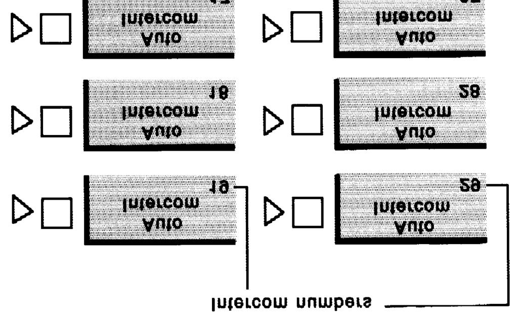
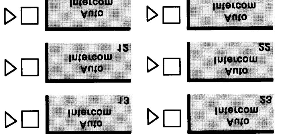
33 Line Assignments When your system is installed and you ve administered it to square or pooled, the system automatically assigns lines to buttons on attendant consoles and voice terminals. You can, however, change these default line assignments for individual attendant consoles or voice terminals. As you fill out this part of the form, refer to the appropriate discussion below, depending on whether you are filling out the form for an attendant console or for a voice terminal in a square system or a voice terminal in a pooled system. ATTENDANT CONSOLES The default line assignments for an attendant console are the same whether a system is square or pooled. The default is that all lines are assigned to the console and each line appears on a separate button. The initial line and feature assignments for the four types of consoles are shown in Figures 2-8 through These diagrams illustrate the order in which lines are assigned to buttons on attendant consoles when your system is first set up. These diagrams also show the features that the system assigns automatically to attendant consoles Fill Out the Voice Terminal Configuration Forms


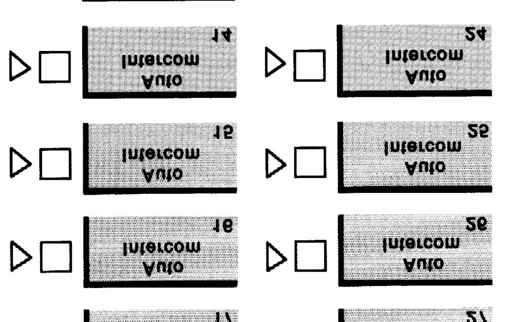
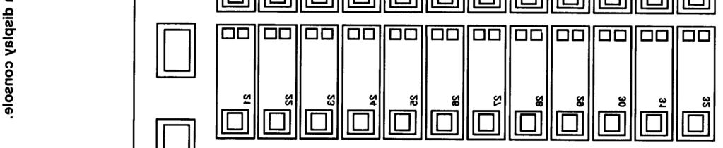
34 FIGURE 2-8 Initial line and feature assignments for a 34-button console for small systems. Fill Out the Voice Terminal Configuration Forms 2-27
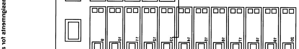
35 FIGURE 2-9 Initial line and feature assignments for a 34-button console for large systems Fill Out the Voice Terminal Configuration Forms
36 Fill Out the Voice Terminal Configuration Forms 2-29


37 2-30 Fill Out the Voice Terminal Conflguratlon Forms
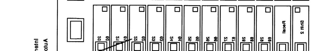
38 Line Buttons The system automatically assigns all your lines to buttons on the attendant console in the order in which the lines are plugged into the control unit. You can change the default arrangement by removing lines or changing the order in which lines are assigned to buttons so that each attendant has the appropriate line assignments. All the attendants in your system may not need the same line assignments. For example, the receptionist needs all the lines except, perhaps, personal lines. A group secretary, on the other hand, only needs lines on which calls come in for his or her group, or lines that group members use to make calls. Members of a sales group, for example, might be assigned certain published local lines and WATS lines that aren t used by other groups in the company. Based on the call-handling responsibilities of your attendants, decide what lines should appear on buttons on their consoles. If two or more attendants have the same call-handling responsibilities, be sure to assign identical line arrangements to their consoles. It s a good idea to record the two-digit line codes on the line buttons on the attendant console. You can get this information from the System Configuration Form. Write the telephone number or name of each line to which this attendant needs access on the appropriate buttons. Follow the order shown in either Figure 2-8, 2-9, 2-10, or 2-11, depending on the type of console you have. Repeat this procedure for each attendant console. If you are using a 34-button console for large systems, read the discussion "Auto Intercom Buttons" below. Auto Intercom Buttons As Figure 2-9 shows, the system doesn t automatically assign any Auto Intercom buttons to the 34-button console for large systems. You can, however, program Auto Intercom buttons on this console, but they can only be used for call handling, not for system administration. Fill in the intercom number and name or location for each Auto Intercom button you want to appear on this attendant console. Continue with Voice Terminals in Square Systems or Voice Terminals in Pooled Systems, as appropriate, to plan line assignments for the voice terminals in your system. VOICE TERMINALS IN SQUARE SYSTEMS When lines are assigned to a voice terminal, they appear on the buttons indicated by the numbers in Figure When a square system is set up, the system automatically assigns lines to the buttons numbered 1 through 8. You can customize this arrangement to better suit your business needs by removing lines, changing the order of lines, or adding lines to voice terminals. FiII Out the Voice Terminal Configuration Forms 2-31


39 FIGURE 2-12 Order in which lines are assigned to buttons in square systems Fill Out the Voice Terminal Configuration Forms
40 In a standard square system, every line appears on each voice terminal. If you want a standard square system, and your system has more than eight lines, you need to assign the additional lines to any 34-button deluxe voice terminals in your system. In a customized square system, individuals or groups of employees have particular combinations of lines to suit their needs. If you want to set up a customized square system, assign the particular lines according to each individual s needs, in the order in which you want them to appear on the voice terminal. Think about the calling patterns and individual responsibilities of the people in your business as you decide what lines should appear on each person s voice terminal buttons. Figure 2-13 shows how a typical business customizes its line assignments. When you have decided on line assignments for each voice terminal, write the telephon numbers in the numbered boxes on the Voice Terminal Configuration Form, beginning with the button above the Intercom-Voice. Fill in the button labeled "1" first, then "2," then "3," and so on. The numbers on the form are there for you convenience. They don't appear on the voice terminal. Example At Ultimate Motors, there are twelve lines assigned to the receptionist s console. The manager needs access to three of those lines: a personal line, the in-state WATS line, and the regional WATS line. The administrator assigns these lines to the first three line buttons on the manager s voice terminal, as shown in Figure The buttons in the second column on the manager s voice terminal are available for custom features. Fill Out the Voice Terminal Configuration Forms 2-33


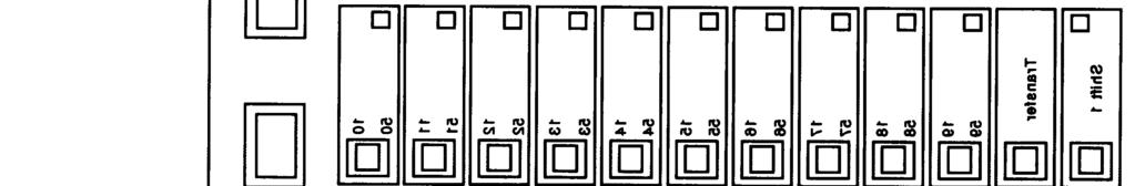
41 FIGURE 2-13 Line assignment for a voice terminal at Ultimate Motors. VOICE TERMINALS IN POOLED SYSTEMS The system initially assigns lines to voice terminals in pooled systems in one of two ways, depending on the pool access method that was chosen. In a system with Button Access, pool 9 is assigned to the first two buttons above Intercom-Voice. You can customize line assignments in a Button Access system by assigning other line pools and/or individual lines to buttons on selected voice terminals. In a system with Dial Access or ARS, the first two buttons above Intercom- Voice are pool access buttons. These buttons provide access to all line pools. You can customize line assignments in a Dial Access or ARS system by assigning individual lines or line pools to buttons on selected voice terminals, or by removing access to certain line pools. The default line assignments for pooled systems are illustrated in Figure Fill Out the Voice Terminal Configuration Forms


42 FIGURE 2-14 The order in which lines and/or line pools are assigned in pooled systems. When you assign line or pools to a voice terminal, they appear on the buttons in the order indicated by the numbers. These two buttons are used to access Pool 9 in a system with Button Access to Line Pools. The buttons are used to access all line pools in a system with Dial Access to Line Pools. Fill Out the Voice Terminal Configuration Forms 2-35
43 Review the responsibilities of the people in your business and the special characteristics of your outside lines. Then decide which line pools and individual lines, if any, to assign to each voice terminal. On each voice terminal configuration form, cross out Pool 9 or if you have DiaI Access to Line Pools or ARS. Likewise, if you have Button Access to Line Pools, cross out or Pool Access on each form. If you plan to assign individual lines or line pools to buttons on this voice terminal, write the line or pool numbers in the numbered boxes representing the buttons on the voice terminal, beginning with the button above Intercom-Voice. Fill in the button labeled 1 first, then 2, then 3, and so on. The numbers on the form are there for your convenience and don t appear on the voice terminal. If you selected Dial Access to Line Pools, list the dial codes of the line pools this voice terminal should be able to use under Dial Access to Pools (9, ). Example The Tenfour Trucking business has expanded and has added an FX and a tie line, and changed their pool access method from Button Access to Dial Access. People now use pool access buttons to get all the line pools. The administrator assigns the manager buttons for a personal line, the tie line, and the FX line, as shown in Figure FiII Out the Voice Terminal Configuration Forms


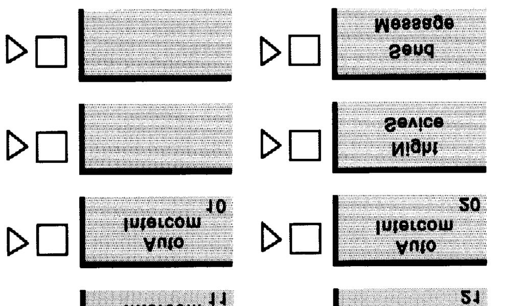
44 FIGURE 2-15 Line assignments for a voice terminal at Tenfour Trucking. Feature Assignments For Office Priorities When you ve finished planning line assignments for your voice terminals, you can stop here and begin administering your system. Continue with the discussions below, however, if you want to customize some voice terminals with features that affect the calling patterns of your business. The rest of the planning forms in this section are optional and apply to options you may want to add to your system. FEATURE ASSIGNMENTS When your system is first set up, it assigns certain features to all attendant consoles, as shown in Figures 2-8 through For a 34-button deluxe console for large systems, however, the system does not automatically assign Night Service and Send Message. On this console, you need to program FiII Out the Voice Terminal Configuration Forms 2-37
45 these features yourself (see Program in Section 6, Reference, for instructions on programming features onto buttons). Nonattendant voice terminals don t have any features assigned to them initially. Most MERLIN II system features are designed solely for the convenience of the person using them and don t affect the system as a whole. Individuals can program those features onto available buttons on their voice terminals at any time to suit their needs. Some features, however, have a broader application because they can affect the calling patterns of your business. These features include Ringing Options Call Coverage Line Pickup Automatic Line Selection You can let people select these features for their own voice terminals or you can decide now which voice terminals should have these features. RINGING OPTIONS The Ringing Options feature lets you customize the ringing on line buttons, pool buttons, and Cover buttons on your voice terminals. You can have incoming calls on these lines ring in one of three different ways: immediate ring, delayed ring, or no ring. When your system is installed, all lines at attendant consoles are set to ring immediately. On nonattendant voice terminals, the initial (default) line ringing assignments are as follows: All individual lines are set to immediate ring. All lines assigned to pool buttons are set to no ring. Customizing line ringing on selected voice terminals is especially useful for Cover buttons and personal lines, as explained below. Considerations Immediate ring. Assign immediate ring to the line of anyone responsible for answering that line first (for example, the attendant, a secretary, or a receptionist). This option is also useful for personal lines that should not be screened or for people who answer their own calls. Delayed ring. Delayed ring provides backup coverage on shared lines. The voice terminal assigned delayed ringing for a certain line doesn t ring unless someone else fails to answer after two rings. Assign delayed ring to a line of anyone who is responsible for answering a shared line if someone else doesn t pick it up, such as a group secretary. Delayed ring may also be useful on an attendant console that backs up your primary attendant console. Also, people may want the attendant to answer calls on their personal lines when they aren t available. In that case, you would set the personal lines for delayed ring at the attendant console Fill Out the Voice Terminal Configuration Forms
46 No ring. Assign no ring to lines on a voice terminal that are always screened first at another voice terminal, such as pooled lines or lines that are answered by a group secretary. This option is also appropriate for voice terminals with no regular users or voice terminals in public places such as lobbies or conference rooms. When you assign no ring to an individual line, the green light next to the line button still flashes when a call comes in on the line. However, if you assign no ring to a pool button, the green light next to the button doesn t flash. Of the lines assigned to the voice terminal, determine which ones should ring immediately at the voice terminal, which should ring after a delay, and which should not ring at all. Decide which voice terminals require special ringing options. On the Voice Terminal Configuration Form for each voice terminal identified, indicate the type of line ringing by writing R (for immediate ringing) or D (for delayed ringing), on the line to the left of each line button. If a line shouldn t ring at the voice terminal, write N for no ring on the line next to its button. Calls transferred on this line will still ring. CALL COVERAGE The Call Coverage feature allows individuals to pick up calls for co-workers with whom they don t share lines by using Cover buttons. This feature is especially useful for attendant consoles, because it lets an attendant cover lines, such as personal lines, that don t appear on his or her console. Call Coverage is also useful to people who frequently work when the attendant is not on duty. If that person has a Cover button for the attendant console, he or she can answer all incoming calls when the attendant isn t there. There are two kinds of coverage: primary and secondary. Assign primary coverage to someone who must answer a co-worker s calls, but doesn t share lines with that person. A secretary who screens someone s calls, for example, would be assigned primary coverage of that person s voice terminal. Assign secondary coverage to anyone who is a second backup for the covered voice terminal. Figure 2-16 illustrates the use of primary and secondary coverage: FiII Out the Voice Terminal Configuration Forms 2-39
, it begins to ring at Bill s voice terminal as well. Jim provides primary coverage for Susan.")
47 FIGURE 2-16 Call coverage at a typical business. Susan s call rings at Jim s voice terminal. If Susan s call isn t answered at Susan s or Jim s voice terminal after 4 rings (delayed ring), it begins to ring at Bill s voice terminal as well. Jim provides primary coverage for Susan. Bill provides secondary coverage for Susan. You can program a primary Cover button for immediate ring, delayed ring, or no ring, depending on the situation and personal preferences. In most cases, a secondary Cover button would be programmed for delayed ring. For more information about line ringing options, see Ringing Options. Considerations The attendant needs a Cover button if he or she covers intercom or transferred calls for anyone. You can assign a maximum of six Call Coverage buttons to a voice terminal. Use only a button with red and green lights next to it. The lights next to a Cover button work like those next to any line button, but you cannot use a Cover button to make a call. Decide which voice terminals require call coverage. On the Voice Terminal Configuration Form for each voice terminal identified, find an available button, write Cover and the name or intercom number of the person whose calls are to be covered. Write P or S on the button to indicate primary or secondary coverage. On the line to the left of the button, write R for immediate ringing, D for delayed ringing, or N for no ring Fill Out the Voice Terminal Configuration Forms
48 LINE PICKUP The Line Pickup feature allows a person to pick up a ringing, parked, or held call at any voice terminal. The attendant or another voice terminal user simply announces the call by intercom or by page, specifying the line number to be picked up. If a voice terminal doesn t have this line number, the person using that voice terminal can still pick up the call using a 2-digit line code, or a code and a button. This feature offers three options: Program individual Line Pickup buttons to pick up specific lines. This places an outward call restriction on the line because the person can pick up calls on that line but cannot make calls. Program a general Line Pickup button that the person can use with a 2-digit line code to pick up any line. Dial *99 and a 2-digit line code to pick up a line. If you want everyone to use the third option, you don t need to plan Line Pickup for your system. Determine which voice terminals require this feature. On the Voice Terminal Configuration Form for each voice terminal identified, check General or Individual under Line Pickup, depending on the type of button(s) the voice terminal should have. For the general Line Pickup feature, write Line Pickup on an available button. On any individual Line Pickup buttons you ve selected, write Pick Up, then the name or number of the line. AUTOMATIC LINE SELECTION When a person lifts the handset to make an outside call, the system automatically checks the outside lines and makes them available in the order in which they were assigned to individual voice terminals. The red light next to that line button shows which line the system will provide when the handset is lifted. The system checks the lines in the order in which they appear on the line buttons on the voice terminal. If you prefer, you can rearrange the line selection sequence if the lines don t appear on the voice terminal in the order in which they are most likely to be used. For example, you may have a standard square system in which the first few lines are all local lines. However, an individual may use a WATS line, personal line, or intercom line most often. You can plan to administer that individual s voice terminal to select automatically the user s preferred line first when he or she picks up the handset. Considerations You may include a maximum of eight lines in an Automatic Line Selection sequence. Determine which voice terminals require a rearrangement of the initial line selection sequence. On the Voice Terminal Configuration Form for each voice terminal identified, enter the preferred sequence of lines under Automatic Line Selection. Fill Out the Voice Terminal Configuration Forms 2-41
49 Keep your completed Voice Terminal Configuration Forms where you can find them easily when you administer the system. You ve now completed the basic planning for your MERLIN II system, and can stop here and begin administering your system. The rest of the planning forms apply to options you may want to add to your system. These include forms for: Enhanced Night Call Restrictions Group Page Group Call Distribution System Speed Dial Service and Allowed Lists Automatic Route Selection 2-42 Fill Out the Voice Terminal Configuration Forms
50 Fill Out Enhanced Night Service Forms The MERLIN II system offers several options for after-hours telephone operation. You can administer these features in any combination to meet the current needs of your business. The three Enhanced Night Service options are summarized below, then explained in more detail in the following pages. Take a few minutes now to read this information to help you decide how you want your system to work. Then fill out the appropriate forms for the Enhanced Night Service option you want. Night Service with Group Assignment lets you specify which voice terminals should ring immediately when after-hours calls come in to an attendant console with which they share lines. For this Night Service option you need to fill out the Enhanced Night Service with Group Assignment Form. Night Service with Outward Restriction lets you set your system so that only authorized users can place nonemergency calls when Night Service is in effect. For this Night Service option you need to fill out the Emergency Allowed List and/or the Exclusion List on the Enhanced Night Service with Outward Restriction Form. Night Service with Time Set lets you set the system to turn Night Service on and off automatically at the times you specify. For this Night Service option you need to fill out the Enhanced Night Service with Time Set Form. NIGHT SERVICE WITH GROUP ASSIGNMENT To make it easier for people in your business to answer after-hours calls, you can assign all the voice terminals associated with a particular attendant console to a Night Service group. Any call that comes in to the attendant console while Night Service is in effect rings at each available voice terminal in the group that has access to that particular line. Calls ring immediately on lines set for delayed ring or no ring at the voice terminals in the group. Considerations As you plan your Night Service groups, keep these points in mind: You can create up to eight Night Service groups. To receive calls, the voice terminals in the group must share lines with the attendant console. You can assign voice terminals to more than one Night Service group. You can put as many voice terminals as you want into a single Night Service group. If your system will have groups of voice terminals associated with attendant positions for answering calls after normal business hours, fill out the Enhanced Night Service with Group Assignment Form. Fill Out Enhanced Night Service Forms 2-43
51 Examples Pooled System Primo Foods has a pooled system, with attendant consoles in the sales, administration, and finance departments. Most of the sales representatives have four line pools assigned to their voice terminals. These line pools are set to no ring for their voice terminals so that the group secretary can screen their calls. The sales director has a personal line that also appears on the secretary s attendant console. Primo s administrator has assigned each sales representative s voice terminal to the Sales Night Service Group. Whenever the group secretary activates Night Service, any call that comes in to the attendant console, except a call on the sales director s personal line, rings immediately at all the voice terminals in the group. The only exception is a voice terminal where the Do Not Disturb feature is in use. Square System The law firm of Smith, Smith, and Jones has a standard square system with only one attendant console. The administrator has set up a single Night Service group containing all the voice terminals. After-hours calls that ring at the receptionist s attendant console ring immediately at all the voice terminals, since each has access to all the lines that appear on the receptionist s console. NIGHT SERVICE WITH OUTWARD RESTRICTION This Night Service feature prevents unauthorized after-hours use of your business telephones. When Night Service with Outward Restriction is in effect, staff members who need to make calls must first enter a password. People who don t know the password can dial only emergency numbers that you specify, such as the telephone numbers for your local police and fire departments. If someone tries to dial a nonemergency number without dialing the password first, the call won t go through. You can create an Exclusion List for voice terminals of people who need to make after-hours calls and prefer not to enter a password. Considerations Once you have administered a password, Night Service with Outward Restriction will be activated for all your voice terminals whenever Night Service is turned on at any attendant console. The password must be four digits. You may use the digits 0 through 9 in any combination. You can include up to ten telephone numbers on the Night Service Emergency Allowed List. Each number can have a maximum of 12 digits. If you assign a voice terminal to the Exclusion List, it keeps its normal call restrictions, if any, while Night Service is in effect. However, it is not protected in any other way from unauthorized after-hours use Fill Out Enhanced Night Service Forms
52 Get the Enhanced Night Service with Outward Restriction Form. On the Emergency Allowed List, enter the numbers you want everyone to be able to call, such as local police and fire departments and ambulance services. On the Exclusion List, enter the intercom numbers of any voice terminals that will be excluded from Night Service protection. Example Primo Foods has Night Service with Outward Restriction. All the voice terminals are restricted while Night Service is in effect except the plant manager s. Because the plant manager would rather not enter a password when he makes after-hours calls, the administrator has assigned the manager s voice terminal to the Exclusion List. Barbara, who manages the Finance Department, often places calls to Primo s West Coast distributors after the department s attendant has left for the day. To do this while Night Service is in effect, Barbara just touches Recall, then dials the 4-digit Night Service password, without lifting her handset. Then she lifts her handset and dials her call. NIGHT SERVICE WITH TIME SET You can administer your system to turn Night Service on and off automatically for all your voice terminals. All you need to do is enter the times at which you want Night Service to go on and off each day. Attendants can override timer-controlled operation and turn Night Service on or off manually if they prefer. In case of shutdowns or midweek holidays, you can suspend Night Service with Time Set indefinitely, then reactivate it. If you want your system to turn Night service on and off automatically, fill in the "on" and "off" times for each day on the Enhanced Night Service with Time Set Table. Use the 24-hour military numbering. If you want Night Service to remain on throughtout the day, on Sunday for example, don't enter "on" or "off" times for that day. Example Primo Foods hours of business are 8:00 a.m. to 5:30 p.m., Monday through Friday. The administrator has set Night Service with Time Set to turn Night Service off and on at these times and to leave Night Service on continuously from Friday evening until Monday morning. Because New Year s Day falls on a Wednesday, Primo s administrator needs to suspend Night Service with Time Set temporarily and keep Night Service in effect from Tuesday night through Thursday morning. He suspends Night Service with Time Set and activates Night Service manually at 5:30 p.m. on Tuesday. It stays on until Thursday morning, when the administrator turns it off manually. During that day, he reactivates Night Service with Time Set. The system resumes automatic control of Night Service and turns it on as usual at 5:30 p.m. You should now have made your decisions about which Enhanced Night Service options you want to use with your system and filled in the forms that pertain to those options. Keep your Night Service forms where you can find them easily when you want to administer your system. Fill Out Enhanced Night Service Forms 2-45
53 Fill Out the Call Restrictions and Allowed-Lists Form CALL RESTRICTIONS When your system is first installed, all voice terminals are unrestricted. This means people can place local and toll calls on all voice terminals. If you want, you can restrict selected voice terminals to intercom or local calls only. If those restrictions are too extreme, you can set up allowed lists, which contain groups of numbers that can be dialed regardless of a voice terminal s call restrictions. You can assign these allowed lists to people who need to call numbers that are outside the general restrictions placed on their voice terminals. Thus, voice terminals can be either unrestricted, outward call restricted, or toll call restricted. Outward Restrictions If you want to allow people to make only internal (intercom) calls, you can place an outward call restriction on their voice terminals. If you want these people to be able to make local calls to certain exchanges, you can set up an allowed list of specific local exchanges. Then you can assign the allowed list to the restricted voice terminals during system administration. The system will then allow calls from the restricted voice terminals to the numbers on the allowed list. NOTE: Outward restricted voice terminals can t be used for emergency calls unless you assign an allowed list of emergency numbers. Toll Call Restrictions If you want to allow people to make only local calls, you can place a toll call restriction on their voice terminals. If there are certain areas of the country to which they may need to place business calls, you can set up allowed lists of those area codes and assign them to the toll restricted voice terminals. Decide which voice terminals should be restricted to intercom calling or local calling. Mark the type of call restriction on the Call Restrictions Form. ALLOWED LISTS Assigning an allowed list adds a group of permitted numbers to the calling range of an outward or toll restricted voice terminal. Permitted numbers consist of an area code, an exchange code (the first three digits of a 7-digit telephone number), both codes, or an emergency number such as 911. Considerations Each entry on an Allowed List can have up to six digits (for example, an area code followed by an exchange). You can create up to eight lists, each containing a maximum of ten allowed numbers. A restricted voice terminal can have access to more than one allowed list. If you want people with restricted voice terminals to be able to place calls to another area code on an FX line or a tie line, enter just the exchange in the Allowed-List Directory. For example, if you have an FX line to the 477 exchange in the 201 area code, you record 477 as the allowed list entry, not Fill Out the Call Restrictions and Allowed-Lists Form
54 If you want restricted voice terminals to be able to call specific area codes or exchanges, group those allowed area codes and/or exchanges into lists. Record the lists of permitted area codes and/or exchanges in the Allowed Lists section of the Call Restrictions and Allowed List Form. Then, on the Call Restrictions part of that form, record the number(s) 0 through 7 of the allowed list(s) each person will have access to on the line for their intercom number. Examples Toll Restricted Voice Terminal A customer York City (area code 212) with a toll restricted with customers in New Jersey (area codes 201 service representative in New voice terminal needs to speak and 609). She is assigned access to Allowed List 2, the New Jersey list, which contains those area codes as shown in Figure FIGURE 2-17 An allowed list for a typical toll-restricted voice terminal Fill Out the Call Restrictions and Allowed-Lists Form 2-47
55 Outward Restricted Voice Terminal A clerk in Houston with an outward restricted voice terminal needs to call several local vendors and the company s headquarters in Chicago. He is assigned Allowed List 3, which includes the first three digits of the local vendors telephone numbers. He is also assigned Allowed List 4, which contains the area code and first three digits of the firm s Chicago telephone number as shown in Figure FIGURE 2-18 An allowed list for a typical outward restricted voice terminal. Keep your completed Call Restrictions and Allowed Lists Form where you can find them easily when you administer the system Fill Out the Call Restrictions and Allowed-Lists Form
56 Fill Out the Group Page Form It may be convenient to page a particular group of employees such as department heads, committee members, or a project team without disturbing the entire staff. The MERLIN II system allows people in your business to page co-workers through their voice terminal speakers. Your business does not need an external paging system for this feature. Considerations You can create up to seven paging groups. Each group can contain as many as ten voice terminals. You can assign a voice terminal to more than one paging group. If you plan to use the Group Page feature, fill in the intercom numbers and names of people assigned to each group. Space is provided next to the group number to write the name of the group. When you have completed the Group Page Form, keep it with the other forms for system administration. Fill Out the Group Page Form 2-49
57 Fill Out the Group Call Distribution Forms Your business may have groups of employees with similar responsibilities, any one of whom can provide information or some other service to callers from inside or outside your business. If you assign their voice terminals to a Call Distribution group, any intercom call to the group rings at the voice terminal of the person whose turn it is to take the next call. If you also assign lines and/or line pools to a Call Distribution group, incoming calls on those outside lines ring at each voice terminal in turn. This feature allows group members to share call-handling responsibilities. Considerations Call Distribution Groups You can establish up to six groups, each containing a maximum of 15 intercom numbers. Voice terminals can belong to more than one group. On the Call Distribution Groups Form, fill in the intercom numbers and names or locations of the members of each group. Space is provided following the group number to identify the group by name. Call Distribution Groups Line/Line Pools Assignments You can assign up to 32 lines or 11 line pools to a Call Distribution Group. All the lines and/or line pools assigned to a Call Distribution Group must appear on all the voice terminals in the group. A line or line pool can be assigned to only one Call Distribution Group. If you plan to assign lines and/or line pools to Call Distribution groups, fill in the lines and/or line pools that will be associated with each group on the Call Distribution Groups Line/Line Pool Assignments Form. Examples Intercom Calls At Primo Foods, order-entry agents handle telephone orders and inquiries about products in the company s retail catalog. Agents often put customers on hold while they get billing information from Accounting or check the status of back-ordered items with Shipping. Because people in those departments belong to Call Distribution groups, an order-entry agent just touches the button for that group. Agents get the information they need without having to look up individuals intercom numbers or make a series of calls because several voice terminals are busy Fill Out the Group Call Distribution Forms
58 Outside Calls At Ultimate Motors, many calls come in daily from people who have questions about the cars the dealership has on its lot and on order. Ultimate s administrator has created a Sales Call Distribution Group consisting of salespeople Joe, Don, Maureen, and Phil. Whenever a call comes in on one of Ultimate s sales lines, the system determines which voice terminal received the last call. If Joe took that call, the system directs the new call to Don s voice terminal. If Don s voice terminal is busy, the call rings at Maureen s voice terminal. The receptionist, whose console is set for delayed ring on this line, answers the call if nobody is available to take it. This arrangement equalizes the salespeople s responsibility for handling inquiries and opportunity to bring new customers in for themselves. When you have completed your Group Call Distribution Forms, keep them with the other forms for system administration. Fill Out the Group Call Distribution Forms 2-51
59 Fill Out the System Speed Dial Form People in your business may dial certain numbers frequently, such as numbers of major clients, suppliers, or branch offices. You can assign system Speed Dial codes to these frequently called numbers and store them in your system. To call these numbers, people just dial the 3-character codes. TELEPHONE NUMBER PRIVACY You may want to assign System Speed Dial codes to telephone numbers that shouldn t be printed in full on call reports, such as numbers that contain access codes. You can mark these numbers as private on the planning form to remind you to encode them as private during system administration. When you list a telephone number on the System Speed Dial Form that you want to mark as private, begin the number with a star. For example, say that you want to assign the code #62 to the number If you want the code rather than the number to print on call reports, enter * next to #62 on the form. Enter the telephone numbers you want to store under System Speed Dial codes in the Telephone Number column of the directory. Enter an identifying name associated with each telephone number in the Name column next to the number. Keep your completed System Speed Dial Form where you can find it easily when you want to administer the system FiII Out the System Speed Dial Form
60 Fill Out the Forms for Automatic Route Selection Using the most economical method available to place each business call can mean significant savings for your company. Routing calls efficiently is especially important if you have several different types of lines, such as local, WATS, Foreign Exchange (FX), or tie line pools, or if you use an alternate long distance company. If your system is pooled, you can use the Automatic Route Selection (ARS) feature to specify which line pool should be used for each call, depending on the telephone number the caller dials. To plan ARS, you first decide what types of calls should be placed on each of your line pools. You record that information on the Automatic Route Selection Worksheet and the Forms for Automatic Route Selection Tables. Later, when you administer your system, you ll enter information from those forms into ARS tables that are stored in your MERLIN II system. HOW ARS WORKS With ARS in place, people just touch the Pool Access button and dial the telephone number they want to reach, without selecting a line pool or dialing special routing digits. Your MERLIN II system places the call using the line pool that you ve designated in your ARS tables as the preferred line pool for a call to that particular area code or exchange. (An exchange is the first three digits of a 7-digit number.) If all the lines in your first-choice line pool are busy, the system routes the call to the second-choice line pool, if you ve specified one, and so on. ARS WORKSHEET Filling out the ARS Worksheet helps you decide how best to route calls, considering the types of line pools you have available. To fill out your ARS Worksheet, follow these steps: 1 In the blank provided at the top of the worksheet, record the number of exchanges in your local calling area. If you aren t sure how many exchanges there are, consult your telephone directory. 2 In the column headed Line Pool Number, enter the number (9, 890 through 899) of each of your line pools. Some line pools, such as in-state WATS line pools, can be used for both toll and local calls. (Note that with ARS a local call is any call that doesn t require dialing an area code. ) If you use a particular line pool for both toll and local calls, enter the number of that line pool in your worksheet twice, with explanatory notes. For example, Sherman Builders Supply is based in Atlanta, Georgia (404 area code). Sherman has a local line pool, an in-state WATS line pool, and a cross-country WATS line pool. Because Georgia has two area codes, 404 and 912, the in-state WATS line can be used for both toll and local calls Therefore, the company s administrator makes two entries for Pool 890 on the ARS Worksheet. Figure 2-19 shows the completed ARS Worksheet for this company. You may find it useful to consult the illustration as you continue filling out your own ARS Worksheet. Fill Out the Forms for Automatic Route Selection 2-53
61 FIGURE 2-19 A completed ARS worksheet for a typical company. Automatic Route Selection Worksheet 2-54 Fill Out the Forms for Automatic Route Selection
62 3 In the column headed Line Type, record the type of line (local, FX, regional WATS, etc. ) for each line pool number you ve entered. 4 In the column headed Type of Dialing, circle the appropriate letter, T or L, for the type of call that should be dialed on each line pool. T = Toll A toll call is a series of digits that begins with a 1, followed by an area code. When placing a toll call using ARS, callers dial 11 digits (1 + 3 [area code] + 3 [exchange] + 4 [last four digits of number]). Keep in mind that, with ARS, callers must dial 1 before dialing the area code, even if they don t normally need to dial a toll prefix to make a long distance call. L = Local Any call that does not fall under the definition of toll. This includes both 7-digit dialing and digit dialing. 5 In the column headed Number of Area Codes or Exchanges for which Line Pool is Used, enter the total number of different area codes or exchanges that each of your line pools should serve. If you don t know the exact number of exchanges or area codes for which you want a line pool to be used, enter a phrase such as All area codes in the U.S. except the 15 served by the regional WATS lines. Keep in mind that you re recording how many different area codes or exchanges each line pool should access, not the area codes or exchanges themselves. This step helps you identify your most general-purpose line pools, that is, the line pools used for calls to many different area codes or exchanges. You need to identify your most general-purpose line pools in order to select default line pools for toll and local calls. Default line pools are the line pools on which the system places each call unless a different route has been specified for that particular type of call. 6 Determine which of your toll line pools is used for calls to the greatest number of different area codes. Write the number of that line pool in the blank next to Default line pool for toll calls: In the example, the cross-country WATS line pool serves the greatest number of different area codes. It is the preferred line pool for calls to every area code in the country except the two area codes in Georgia. Therefore, the administrator makes it the default line pool for toll calls. 7 Determine which of your local line pools is used for calls to the greatest number of different exchanges. Write the number of that line pool in the blank next to Default line pool for local calls: In the example, the in-state WATS line pool serves the largest number of different exchanges. It s the preferred line pool for calls to every exchange in area code 404 except the 20 exchanges in the local calling area. Therefore, the administrator makes it the default line pool for local calls. ABOUT ARS TABLES You ll use the information you recorded on your ARS Worksheet to prepare Forms for Automatic Route Selection Tables. When you administer ARS, you ll enter information from these forms into ARS tables stored in your MERLIN II system. These tables tell the system which line pool to use to place each outgoing call. Fill Out the Forms for Automatic Route Selection 2-55
63 Before you go on to Forms for ARS Tables to begin filling out these forms for your business, review the following general information about ARS tables. Tables 0 through 7 You can set up as many as eight tables, numbered 0 through 7, to route calls to specific area codes and exchanges for which you have economical line pools, such as in-state or regional WATS, FX, or tie line pools. How many of these tables you ll need depends on the number of different routing patterns you want to set up to make the best use of your different line pools. The forms for Tables 0 through 7 have two sections: an Area Code/Exchanges section and a Pool, Other Digits, and Absorb section. Tables 8 and 9, the Default Tables You ll set up two default tables, one for toll calls and the other for local calls. Having these default tables minimizes the time it takes to plan and administer ARS, since you don t have to record the area codes and exchanges served by your most general-purpose line pools. Table 8, the Default Toll Table, routes toll calls to all area codes that aren t listed in Tables 0 through 7. Table 9, the Default Local Table, routes local calls to all exchanges that aren t listed in Tables 0 through 7. Since the default function makes it unnecessary to record all the possible area codes and exchanges served by these line pools, the forms for these tables have just one section, a Pool, Other Digits, and Absorb section. The Special Number Table The Special Number Table routes calls to these numbers: 0, 411, 611, 911, 800, and 900. If people in your business must dial an access number such as 9 in order to dial one of these special numbers, you ll need to enter that information in the form for the Special Number Table, in the column headed Other Digits. 3-Digit vs. 6-digit Tables Many businesses use only one type of line, such as a regional WATS line, for all calls placed to a particular area code. These calls are routed according to tables that associate the area code with the preferred line pool. They are called 3-digit tables because the system needs to scan only the area code of the number being dialed in order to route the call properly. For some businesses, however, the cost of long distance calls to telephone numbers in another area code varies according to the exchange the caller dials. In these cases, the system may be set up to place calls to numbers in a particular area code on different line pools, depending on the exchange to which the call is placed. These calls are routed according to tables that associate an area code and one or more exchanges with the preferred line pool. They are called 6-digit tables because the system needs to scan both the area code and the exchange of the number being dialed in order to route the call properly FiII Out the Forms for Automatic Route Selection
64 Tables that route local calls are always 3-digit tables, since the system needs to scan only the exchange in order to place the call on the preferred line pool. In summary: A 3-digit table lists either area codes or exchanges, then specifies the line pool(s) on which the system should place calls to those area codes or exchanges. A 6-digit table lists a single area code, followed by one or more exchanges within that area code, then specifies the line pool(s) on which the system should place calls to those exchanges. Digit Absorption The column headed Absorb on the Forms for Automatic Route Selection Tables specifies how many, if any, of the digits dialed by the caller should be absorbed (not dialed) by the system when it places these calls. This is done to be sure you get the full benefit from any special-purpose lines in your system such as FX lines and tie lines. You include an absorption type (see list below) in your tables so that the system can route all appropriate calls to these lower-cost line pools. Digit absorption doesn t interfere with Call Report or Call Restriction, if you administer those features. The digits dialed by the caller are recorded on call reports, while the digits dialed by the system are checked to be sure the call is allowed. The factory-set value for the absorption type is 0, which means the system places a call using all the digits that the caller dialed. The other five absorption types tell the system not to dial certain digits dialed by the caller. The six possible absorption types are: No absorption (absorption type 0, the default setting) The leading 1 (absorption type 1) The area code (absorption type 2) 1 plus the area code (absorption type 3) 1 plus the exchange (absorption type 4) 1 plus the area code plus the exchange (absorption type 5) For example, a branch office in Bowling Green, Ohio has a tie line pool to company headquarters in Detroit, Michigan. The complete telephone number at headquarters is an 11-digit number, 1 + the area code + the 7-digit number. People in the branch office dial all eleven digits, but the system dials only the last four digits to place these calls. This happens because the branch office administrator has associated absorption type 5 with the tie line pool in the ARS table that routes calls to this area code and exchange. The absorption type entry in the table tells the system to absorb the 1, the area code, and the exchange, so that the call can be placed on one of the tie lines. Fill Out the Forms for Automatic Route Selection 2-57
65 FORMS FOR ARS TABLES Now you re ready to fill out your Forms for Automatic Route Selection Tables. If you haven t already done so, get the 9 pages of forms for ARS tables provided at the end of this section of the manual. Make copies of the forms and return the originals to the manual. Keep your completed ARS Worksheet handy too. You ll probably need to refer to your worksheet as you fill out forms for the tables that you need. About the Forms Forms are provided for Tables 0 through 9 and for the Special Numbers Table. Note that 3-character administration codes (shaded) and either 2-digit entry numbers (00 through 99) or 1-digit entry numbers (0 through 5) are preprinted on the forms. This is done to save you time when you enter the information from your forms into your MERLIN II system. For example, the preprinted information for the first entry in the Area Code/Exchanges section of Table 0 is shown in Figure FIGURE 2-20 An example of preprinted information on a Form for Automatic Route Selection Table. Considerations Keep these points in mind as you fill out forms for ARS tables: Remember to number your tables to allow for future growth. Use the Form for Automatic Route Selection Table 0 to plan your first 6-digit table and fill out forms for any other 6-digit tables so that the tables are numbered sequentially in ascending order (Table 1, Table 2, etc.). Use the Form for Automatic Route Selection Table 7 to plan your first 3-digit table and fill out forms for any other 3-digit tables so that the tables are numbered sequentially in descending order (Table 6, Table 5, etc.). This makes it possible for your system to distinguish between the two types of tables. This numbering system also lets you add 3-digit or 6-digit tables later without having to change your existing tables. In the Area Code/Exchanges section of a form for a 3-digit table, you can list up to 100 area codes or exchanges, in any order. On the form for a 6-digit table, you record an area code as the first entry, followed by up to 99 exchanges, listed in any order. If you need to list more area codes or exchanges, prepare a form for a second table Fill Out the Forms for Automatic Route Selection
66 Procedure for Filling Out Forms for ARS Tables Follow these steps to fill out your Forms for Automatic Route Selection Tables: 1 Get the Form for Automatic Route Selection Table 0. Decide how many 6-digit tables you need (you can have none or as many as eight). Enter that number (0 through 8) at the top of the form, in the blank next to Total number of 6-digit tables: 2 If you plan to have one or more 6-digit tables, go on to step 3 to continue filling out the form for Table 0. If you don t need any 6-digit tables, put the form for Table 0 aside, get the form for Table 7, and go on to step 3. 3 On the line next to Is this a 6-digit table?, circle y for yes or n for no as appropriate. 4 To fill out the section of the form headed Area Code/Exchanges, perform one of the following actions: If this is a form for a 6-digit table, write the area code in the blank provided for the first entry, entry 00. Then write each exchange within that area code that your people would call in the numbered blanks, beginning with the blank for entry 01. For example, say that an administrator plans to use Table 0 to route calls to exchanges 333, 444, and 523 in area code 816. The upper section of the completed form looks similar to the one shown in Figure FIGURE 2-21 An example of an area code and exchanges entered in a 6-digit table. Fill Out the Forms for Automatic Route Selection 2-59
67 If this is a form for a 3-digit table, write the area codes or exchanges in the blanks provided, beginning with the blank for the first entry, entry 00. For example, say that an administrator plans to use Table 7 to route calls to the Northeastern (Band 1) WATS lines. The administrator records the 13 area codes served by the Northeastern WATS lines as entries 00 through 12. The upper section of the completed form looks similar to the one shown in Figure FIGURE 2-22 An example of area codes in a 3-digit table. 5 To fill out the column headed Pool, write the number of the preferred line pool in the space provided for the first entry, entry 0. This is the line pool on which calls to the area codes or exchanges listed in the Area Code/Exchanges section of this form should be placed. If you want to designate a backup line pool in case all the lines in your first-choice line pool are busy, write the number of the backup line pool in the blank for the second entry, and so on. For example, on the form for a typical 3-digit table illustrated in step 4 (Figure 2-22), the administrator is planning a table to route calls to the 13 area codes served by the Northeastern (Band 1) WATS lines. To specify the Northeastern WATS line pool as the pool of choice for calls to these area codes, the administrator records as entry 0 in the column headed Pool the number of the Northeastern WATS line pool, 891. See Figure Fill Out the Forms for Automatic Route Selection
68 FIGURE 2-23 An example of entering line pool numbers in a 3-digit table. Because calls to these 13 area codes should be placed on the cross-country WATS lines if all the Northeastern WATS lines are busy, the administrator records as entry 1 the number of the cross-country WATS line pool, Pool Extra digits or special characters may be required in order for your system to place a call on a particular line pool. If so, enter the digits or characters in the same row as the pool number, in the column headed Other Digits. These special access or account codes can range from a single digit, such as 9, to a maximum of 20 characters, including symbols for pause (p), switchhook flash (r), and Touch-Tone enable (t). (See Special Characters in Programmed Dialing Sequences in Section 6, Reference. ) For example, say that a firm uses an alternate long distance company for calls to nine area codes in Canada. Accessing the alternate long distance company lines requires getting a local line, dialing seven digits, waiting for a dial tone, then dialing six more digits and waiting for a dial tone again. The administrator records the digits and a p (pause) for each second that the system should wait before continuing the dialing sequence. The completed form for the 3-digit table that routes these calls to the alternate long distance company lines is shown in Figure Fill Out the Forms for Automatic Route Selection 2-61
69 FIGURE 2-24 An example of other digits needed to access line pools on a 3-digit table. 7 If your system needs to absorb certain digits dialed by callers in order to place calls on a particular line pool, enter the appropriate absorption number in the same row as the pool number, in the column headed Absorb. These are the absorption numbers: 0 = No absorption 1 = Leading 1 2 = Area code only 3 = 1 + area code 4 = 1 + exchange 5 = 1 + area code + exchange For example, say that a company has FX lines for the 686 exchange in the 901 area code. To allow people to dial those calls the same way they dial toll calls to other area codes, the administrator associates absorption number 3 with the FX line pool, Pool 893. The completed form for the 6-digit table that routes calls to the FX line pool is shown in Figure Fill Out the Forms for Automatic Route Selection
70 FIGURE 2-25 An example of absorption numbers need to access line pools on a 6-digit table After ARS is administered, people in this company dial XXXX to make these calls. The system absorbs the leading 1 and the area code and dials only the 7-digit number in order to place these calls on one of the FX lines. Repeat steps 3 through 7 to fill out a form for each nondefault table (Tables 0 through 7) that you need. Turn to the Forms for Automatic Route Selection Default and Special Numbers Tables. Referring to your ARS Worksheet, perform steps 5 through 7 to fill out the forms for the Default Toll Table (Table 8) and the Default Local Table (Table 9). People in your business may need to dial an access code in order to make calls to the special numbers 0, 411, 611, 911, 800 and 900. If so, record that code on the form for the Special Number Table, in the blank under the heading Other Digits. You now have all the information you need to set up ARS for your business. Place your completed ARS forms where you can find them easily when you re ready to administer your system. Fill Out the Forms for Automatic Route Selection 2-63
71 Master Planning Form Line Jacks Line Jack Telephone No. or Line Equipment Jack Telephone No. or Equipment Module location Basic unit Expansion unit Slot identification: Master Planning Form 2-65
72 Master Planning Form Station Jacks Station Jack Jack Type (A,D,B) Person, Location, or Function A 47 A A A A A Jack Station Type Person, Location, Jack (A,D,B) or Function Master Planning Form
73 System Configuration Form System Size: Small (1-8 Lines) Large (>8 Lines) Line Representation: Square Pooled Button Access Dial Access Automatic Route Selection Attendant Stations: Administrator/Attendant Console: 34-Button Console for Small Systems 34-Button Console for Large Systems 34-Button Console with AIS Display Console Call Report Options: Outgoing Calls Only Incoming and Outgoing Calls Minimum Length of Calls Recorded (Minutes) Transfer Return Interval: Number of Rings One-Touch Call Handling: One-Touch Transfer One-Touch Hold with Call Announcement Toll Prefix Line Telephone No. Line Type if Line Pool not needed Jack or Equipment Other than Local (9, ) Rotary? for Long Dist? System Configuration Form 2-67

74 Voice Terminal Configuration Form Attendant Consoles Intercom No. Identification Console Model: 34-Button Deluxe 34-Button Deluxe with AIS Display Console Accessories: General Purpose Adapter Headset Headset Adapter Hands-Free Unit Extra-Long Cord Acoustic Coupler Adapter Hearing-lmpalred Handset Push-to-Listen Handset Voice Terminal Power Supply On the 34 button console for small systems, the system automatically assigns the Auto Intercom, Night Service, and Send Message features to buttons, as shown by the labels in the upper left - hand corner. If some of these buttons aren t needed as Auto Intercom buttons, you can assign other features to them. Voice Terminal Conflguratlon Form 2-69
75 Voice Terminal Configuration Form Analog Voice Terminals (Square Systems) Intercom No. Identification Voice Terminal Model: 5-Button 10-Button 10-Button HFAI 34-Button Deluxe 34-Button BIS 34-Button BIS with Display Basic Touch-Tone or Rotary Telephone Accessories: General Purpose Adapter Headset Headset Adapter Hands-Free Unit Extra-Long Cord Acoustic Coupler Adapter Hearing-lmpalred Handset Push-to-Listen Handset Voice Terminal Power Supply Line Pickup: General Indlvidual Automatic Line Selection: Night Service Exclusion: Yes No Voice Terminal Configuration Form 2-71
76 Voice Terminal Configuration Form Digital Voice Terminals (Square Systems) Intercom No. Identification Voice Terminal Model: 7406B 7406D Accessories: General Purpose Adapter Headset Headset Adapter Hands-Free Unit Acoustic Coupler Adapter Hearing-Impaired Handset Push-to-Listen Handset Voice Terminal Power Supply Line Pickup: General Individual Automatic Line Selection: Night Service Exclusion: Yes No 2-72 Voice Terminal Configuration Form
77 Voice Terminal Configuration Form Analog Voice Terminals (Pooled Systems) Intercom No Identification Voice Terminal Model: Accessories: 5-Button General Purpose Adapter Acoustic Coupler Adapter 10-Button Headset Hearing-Impaired Handset 10-Button HFAI Headset Adapter Push-to-Listen Handset 34-Button Deluxe Hands-Free Unit Voice Terminal Power Supply 34-Button Deluxe BIS Extra-Long Cord 34-Button Deluxe BIS with Display Basic Touch-Tone or Rotary Telephone When line pools or lines are assigned to a voice terminal, they appear on buttons in the order indicated. Dial Access to Pools (9, ): Line Pickup: General Individual Automatic Line Selection: Night Service Exclusion: Yes No Voice Terminal Configuration Form 2-73
78 Voice Terminal Configuration Form Digital Voice Terminals (Pooled Systems) Intercom No. Identification Voice Terminal Model: 7406B 7406D Accessories: General Purpose Adapter Headset Headset Adapter Hands-Free Unit Acoustic Coupler Adapter Hearing-lmpaired Handset Push-to-Listen Handset Voice Terminal Power Supply Dial Access to Pools (9, ): Line Pickup: General Individual Automatic Line Selection Night Service Exclusion: Yes No 2-74 Voice Terminal Configuration Form
79 Enhanced Night Service with Group Assignment Form Attendant Attendant Attendant Attendant Icom Icom Icom Icom No. Name No. Name No. Name No. Name Enhanced Night Service with Group Assignment Form 2-75
80 Enhanced Night Service with Group Assignment Form (Continued) Attendant Attendant Attendant Attendant Icom Icom Icom Icom No. Name No. Name No. Name No. Name Enhanced Night Service with Group Assignment Form
81 Enhanced Night Service with Outward Restriction Form Password: (Note: If you want to keep your password private, do not fill in the blank.) Emergency Allowed List Entry Telephone No Exclusion List (Voice Terminals not Restricted During Night Service) Icom Icom Icom No. Name No. Name No. Name Enhanced Night Service with Outward Restriction Form 2-77
82 Enhanced Night Service with Time Set Form Day Sunday Monday Tuesday Wednesday Thursday Friday Saturday Service Off Service On Enhanced Night Service with Time Set activated on (day of week): 2-78 Enhanced Night Service with Time Set Form
83 Call Restrictions and Allowed Lists Forms Call Restrictions Icom Outward Toll Allowed Lists Icom Outward Toll Allowed Lists No. Restricted Restricted Unrestricted Assigned No. Restricted Restricted Unrestricted Assigned Call Restrictions and Allowed Lists Forms 2-79
84 Allowed Lists List 0 List 1 List 2 List 3 Entry No. Entry Entry Entry Entry No. Entry No. Entry No. Entry List 4 List 5 List 6 List 7 Entry No. Entry Entry No. Entry Entry No. Entry Entry No. Entry Call Restrictions and Allowed Lists Forms
85 Group Page Form Group 1 Group 2 Icom No. Name or Location Icom No. Name or Location Group 3 Group 4 Icom No. Name or Location Icom No. Name or Location Group Page Form 2-81
86 Group 5 Group 6 Icom No. Name or Location Icom No. Name or Location Group 7 Icom No. Name or Location Group Page Form
87 Group Call Distribution Forms Call Distribution Groups Group 0 Group 1 Group 2 Icom No. Identification Icom No. Identification Icom No. Identification Group 3 Group 4 Icom No. Identification Icom No. Identification Group 5 Icom No. Identification Group Call Distribution Forms 2-83
88 Group Call Distribution Forms Call Distribution Groups Line/Line Pool Assignments Group 0 Group 1 Group 2 Line or Line Pool No. Line or Line Pool No. Line or Line Pool No Group Call Dlstrlbution Forms 2-85
89 Group Call Distribution Forms Call Distribution Groups Line/Line Pool Assignments (Continued) Group 3 Group 4 Group 5 Line or Line Pool No. Line or Line Pool No. Line or Line Pool No Group Call Dlstribution Forms
90 System Speed Dial Form Dial Code Telephone Number Name #60 #61 #62 #63 #64 #65 #66 #67 #68 #69 #70 #71 #72 #73 #74 #75 #76 #77 #78 #79 #80 #81 #82 #83 #84 #85 #86 #87 #88 #89 #90 #91 #92 #93 #94 #95 #96 #97 #98 #99 System Speed Dial Form 2-87
91 Automatic Route Selection Worksheet Number of exchanges in your calling area Line Pool Type of Number of Area Codes or Exchanges Number Line Type Dialing for which Line Pool is Used T L T L T L T L T L T L T L T L T = Toll, L = Local Default line pool for toll calls: Default line pool for local calls: Automatic Route Selection Worksheet 2-89
92 Form for Automatic Route Selection Table 0 Total number of 6-digit tables: Is this a 6-digit table? Y N #6000 #6005 #6010 #6015 #6020 #6025 #6030 #6035 #6040 #6045 #6050 #6055 #6060 #6065 #6070 #6075 #6080 #6085 #6090 #6095 Area Code/Exchanges #6001 #6002 #6003 #6004 #6006 #6007 #6008 #6009 #6011 #6012 #6013 #6014 #6016 #6017 #6018 #6019 #6021 #6022 #6023 #6024 #6026 #6027 #6028 #6029 #6031 #6032 #6033 #6034 #6036 #6037 #6038 #6039 #6041 #6042 #6043 #6044 #6046 #6047 #6048 #6049 #6051 #6053 #6052 #6054 #6056 #6057 #6058 #6059 #6061 #6062 #6063 #6064 #6066 #6067 #6068 #6069 #6071 #6072 #6073 #6074 #6076 #6077 #6078 #6079 #6081 #6082 #6083 #6084 #6086 #6087 #6088 #6089 #6091 #6092 #6093 #6094 #6097 #6096 #6098 #6099 #700 #701 # #703 #704 #705 Pool Other Digits Absorb # # # # # # Form for Automatic Route Selection Table
93 Form for Automatic Route Selection Table 1 Is this a 6-digit table? Y N #6100 #6105 #6110 #6115 #6120 #6125 #6130 #6135 #6140 #6145 #6150 #6155 #6160 #6165 #6170 #6175 #6180 #6185 #6190 #6195 #6101 #6106 #6111 #6116 #6121 #6126 #6131 #6136 #6141 #6146 #6151 #6156 #6161 #6166 #6171 #6176 #6181 #6186 #6191 #6196 Area Code/Exchanges #6102 #6107 #6112 #6117 #6122 #6127 #6132 #6137 #6142 #6147 #6152 #6157 #6162 #6167 #6172 #6177 #6182 #6187 #6192 #6197 #6103 #6108 #6113 #6118 #6123 #6128 #6133 #6138 #6143 #6148 #6153 #6158 #6163 #6168 #6173 #6178 #6183 #6188 #6193 #6198 #6104 #6109 #6114 #6119 #6124 #6129 #6134 #6139 #6144 #6149 #6154 #6159 #6164 #6169 #6174 #6179 #6184 #6189 #6194 #6199 Pool #710 #711 #712 #713 #714 #715 Other Digits Absorb #710 #711 #712 #713 #714 # Form for Automatic Route Selection Table 1
94 Form for Automatic Route Selection Table 2 Is this a 6-digit table? Y N #6200 #6205 #6210 #6215 #6220 #6225 #6230 #6235 #6240 #6245 #6250 #6255 #6260 #6265 #6270 #6275 #6280 #6285 #6290 #6295 #6201 #6206 #6211 #6216 #6221 #6226 #6231 #6236 #6241 #6246 #6251 #6256 #6261 #6266 # #6281 #6286 #6291 #6296 Area Code/Exchanges #6202 #6207 #6212 #6217 #6222 #6227 #6232 #6237 #6242 #6247 #6252 #6257 #6262 #6267 #6272 #6277 #6282 #6287 #6292 #6297 #6203 #6208 #6213 #6218 #6223 #6228 #6233 #6238 #6243 #6248 #6253 #6258 #6263 #6268 #6273 #6278 #6283 #6288 #6293 #6298 #6204 #6209 #6214 #6219 #6224 #6229 #6234 #6239 #6244 #6249 #6254 #6259 #6264 #6269 #6274 #6279 #6284 #6289 #6294 #6299 Pool Other Digits Absorb #720 #721 #722 #723 #724 #725 #720 #721 #722 #723 #724 #725 Form for Automatic Route Selection Table
95 Form for Automatic Route Selection Table 3 Is this a 6-digit table? Y N #6300 #6301 Area Code/Exchanges #6302 #6303 #6304 #6305 #6306 #6307 #6308 #6309 #6310 #6311 #6312 #6313 #6314 #6315 #6316 #6317 #6318 #6319 #6320 #6321 #6322 #6323 #6324 #6325 #6326 #6327 #6328 #6329 #6330 #6331 #6332 #6333 #6334 #6335 #6336 #6337 #6338 #6339 #6340 #6341 #6342 #6343 #6344 #6345 #6346 #6347 #6348 #6349 #6350 #6351 #6352 #6353 #6354 #6355 #6356 #6357 #6358 #6359 #6360 #6361 #6362 #6363 #6364 #6365 #6366 #6367 #6368 #6369 #6370 #6371 #6372 #6373 #6374 #6375 #6376 #6377 #6378 #6379 #6380 #6381 #6382 #6383 #6384 #6385 #6386 #6387 #6388 #6389 #6390 #6391 #6392 #6393 #6394 #6395 #6396 #6397 #6398 #6390 Pool Other Digits Absorb #730 #730 #731 #731 #732 #732 #733 #733 #734 #734 #735 # Form for Automatic Route Selection Table 3
96 Form for Automatic Route Selection Table 4 Is this a 6-digit table? Y N #6400 #6401 Area Code/Exchanges #6402 #6403 #6404 #6405 #6406 #6407 #6408 #6409 #6410 #6411 #6412 #6413 #6414 #6415 #6416 #6417 #6418 #6419 #6420 #6421 #6422 #6423 #6424 #6425 #6426 #6427 #6428 #6429 #6430 #6431 #6432 #6433 #6434 #6435 #6436 #6437 #6438 #6439 #6440 #6441 #6442 #6443 #6444 #6445 #6446 #6447 #6448 #6449 #6450 #6451 #6452 #6453 #6454 #6455 #6456 #6457 #6458 #6459 #6460 #6461 #6462 #6463 #6464 #6465 #6466 #6467 #6468 #6469 #6470 #6471 #6472 #6473 #6474 #6475 #6476 #6477 #6478 #6479 #6480 #6481 #6482 #6483 #6484 #6485 #6486 #6487 #6488 #6489 #6490 #6491 #6492 #6493 #6494 #6495 #6496 #6497 #6498 #6499 Pool Other Digits Absorb #740 #741 #742 #743 #744 #745 #740 #741 #742 #743 #744 #745 Form for Automatic Route Selection Table
97 Form for Automatic Route Selection Table 5 Is this a 6-digit table? Y N #6500 #6505 #6510 #6515 #6520 #6525 #6530 #6535 #6540 #6545 #6550 #6555 #6560 #6565 #6570 #6575 #6580 #6585 #6590 #6595 #6501 #6506 #6511 #6516 #6521 #6526 #6531 #6536 #6541 #6546 #6551 #6556 #6561 #6566 #6571 #6576 #6581 #6586 #6591 #6596 Area Code/Exchanges #6502 #6507 #6512 #6517 #6522 #6527 #6532 #6537 #6542 #6547 #6552 #6557 #6562 #6567 #6572 #6577 #6582 #6587 #6592 #6597 #6503 #6508 #6513 #6518 #6523 #6528 #6533 #6538 #6543 #6548 #6553 #6558 #6563 #6568 #6573 #6578 #6583 #6588 #6593 #6598 #6504 #6509 #6514 #6519 #6524 #6529 #6534 #6539 #6544 #6549 #6554 #6559 #6564 #6569 #6574 #6579 #6584 #6589 #6594 #6599 Pool Other Digits Absorb #750 #751 #752 #753 #754 #755 #750 #751 #752 #753 #754 # Form for Automatic Route Selection Table 5
98 Form for Automatic Route Selection Table 6 Is this a 6-digit table? Y N #6600 #6605 #6610 #6615 #6620 #6625 #6630 #6635 #6640 #6645 #6650 #6655 #6660 #6665 #6670 #6675 #6680 #6685 #6690 #6695 #6601 #6606 #6611 #6616 #6621 #6626 #6631 #6636 #6641 #6646 #6651 #6656 #6661 #6666 #6671 #6676 #6681 #6686 #6691 #6696 Area Code/Exchanges #6602 #6607 #6612 #6617 #6622 #6627 #6632 #6637 #6642 #6647 #6652 #6657 #6662 #6667 #6672 #6677 #6682 #6687 #6692 #6697 #6603 #6608 #6613 #6618 #6623 #6628 #6633 #6638 #6643 #6648 #6653 #6658 #6663 #6668 #6673 #6678 #6683 #6688 #6693 #6698 #6604 #6609 #6614 #6619 #6624 #6629 #6634 #6639 #6644 #6649 #6654 #6659 #6664 #6669 #6674 #6679 #6684 #6689 #6694 #6699 Pool Other Digits Absorb #760 #761 #762 #763 #764 #765 #760 #761 #762 #763 #764 #765 Form for Automatic Route Selection Table
99 Form for Automatic Route Selection Table 7 Is this a 6-digit table? Y N #6700 #6705 #6710 #6715 #6720 #6725 #6730 #6735 #6740 #6745 #6750 #6755 #6760 #6765 #6770 #6775 #6780 #6785 #6790 #6795 #6701 #6706 #6711 #6716 #6721 #6726 #6731 #6736 #6741 #6746 #6751 #6756 #6761 #6766 #6771 #6776 #6781 #6786 #6791 #6796 Area Code/Exchanges #6702 #6707 #6712 #6717 #6722 #6727 #6732 #6737 #6742 #6747 #6752 #6757 #6762 #6767 #6772 #6777 #6782 #6787 #6792 #6797 #6703 #6708 #6713 #6718 #6723 #6728 #6733 #6738 #6743 #6748 #6753 #6758 #6763 #6768 #6773 #6778 #6783 #6788 #6793 #6798 #6704 #6709 #6714 #6719 #6724 #6729 #6734 #6739 #6744 #6749 #6754 #6759 #6764 #6769 #6774 #6779 #6784 #6789 #6794 #6799 Pool #770 #771 #772 #773 #774 #775 Other Digits Absorb #770 #771 #772 #773 #774 # Form for Automatic Route Selection Table 7
100 Form for ARS Default and Special Number Tables FORM FOR TABLE 8: DEFAULT TOLL TABLE Pool #780 #781 #782 #783 #784 #785 Other Digits Absorb #780 #781 #782 #783 #784 #785 FORM FOR TABLE 9: DEFAULT LOCAL TABLE Pool #790 #791 #792 #793 #794 #795 Other Digits Absorb #790 #791 #792 #793 #794 #795 FORM FOR SPECIAL NUMBERS TABLE (411, 611, 911, 800, 900, 0) Pool 9 #800 Other Digits Absorb 0 Form for ARS Default and Special Number Tables 2-99
101 Overview The advanced technology of the MERLIN II Communications System allows you to customize the system to meet your particular business communication needs. As system administrator, you ll probably be responsible for establishing the basic operating conditions of your MERLIN II system right after installation. This includes such essential steps as setting the system size and assigning lines to voice terminals. You can set up optional systemwide features such as Call Restriction, Group Page, and Automatic Route Selection during your first administration session. Or, if you prefer, you can add them later, according to your business priorities. And if your needs change over time, you can easily alter your MERLIN II system to meet your new communication requirements. THE DIFFERENCE BETWEEN ADMINISTRATION AND PROGRAMMING Because the effects of system administration are wide-ranging, only you or someone you delegate should perform administration procedures. It s important to understand the difference between the changes you make to the system when you administer it and changes that people make to their own voice terminals when they program them. The term administer as used in this manual refers to the act of setting up options and features that have systemwide impact or that provide telephone security. This includes such actions as creating line pools and restricting the dialing area of selected voice terminals. You use the administrator/attendant console (the voice terminal that has intercom number 10) to administer your system. To perform administration, you put the system in a special state of operation called administration mode. The term program refers to assigning optional features to an individual voice terminal. Anyone can put a voice terminal in programming mode and assign features to it. Programmable features don t affect the system as a whole or involve calling restrictions. HOW TO USE THIS SECTION OF THE MANUAL How you use this section of the manual depends on the type of system you have. If you re administering a newly installed system, follow the steps under Setting Up a New System. If you re administering an existing system, follow the steps under Making Changes to a System. Setting Up a New System Read the following if your system is newly installed: 1 Follow the instructions in Step 1: Gather the Planning Forms and Label the Buttons. This involves collecting the forms that you filled out in Section 2, Planning the System, and labeling the buttons on the administrator/attendant console. 2 Read through Step 2: Learn About the System Components, to familiarize yourself with the MERLIN II equipment. 3 Read the introductory material in Step 3: Perform Basic Administration. Then perform the procedures required for your system. 4 Get your completed planning forms and review the system options you selected. Turn to Step 4: Customize with Optional Systemwide Features, and perform the appropriate procedures. Overview 3-1
102 5 If you want to assign features to individual voice terminals, get your completed Voice Terminal Configuration Forms and review the features you selected. Turn to Step 5: Program Voice Terminals for Office Priorities, and complete the appropriate procedures. 6 If your system has basic telephones, turn to Step 6: Administer Basic Telephones, and follow the instructions. Making Changes to a System Read the following if you need to change an administered system: Locate the completed forms for the system settings or features you plan to change. If you aren t familiar with the MERLIN II system, read Step 2: Learn About the System Components. Read If You Make Basic Changes to an Administered System in Step 3: Perform Basic Administration. Record the changes you plan to make on the appropriate forms. If you need just the steps for changing settings or features, find the appropriate procedures in Quick Reference Guide to System Administration, found in Section 7, Quick Reference Guides. If you want complete descriptions and detailed instructions, turn to the appropriate entries in this section of the manual or in Section 6, Reference. 3-2 Overview
103 Step 1: Gather the Planning Forms and Label the Buttons PLANNING FORMS When you ordered your MERLIN II system, you may have received a MERLIN II Planning Guide. It contains the forms listed below. Master Planning Form System Configuration Form Voice Terminal Configuration Forms Enhanced Night Service Forms Call Restrictions and Allowed Lists Forms Group Page Form Group Call Distribution Forms System Speed Dial Form Forms for Automatic Route Selection Tables You use the completed forms to set up your MERLIN II system for the first time and to make changes to your system. If you haven t filled out the forms that apply to your system, do so now. Section 2, Planning the System, contains copies of the forms and instructions for completing them. Keep the completed forms handy. You ll refer to them when you perform most administration procedures. ADMINISTRATOR/ Your administrator/attendant console, the voice terminal at intercom number ATTENDANT CONSOLE 10, came with a sheet of labels for recording telephone numbers and features BUTTON LABELS assigned to buttons. Before you begin administering your system, you need to label the buttons on your console. If you haven t already done so, get the Voice Terminal Configuration Form for your administrator/attendant console. It shows what telephone number or feature, if any, should be assigned to each button on the console. The bottom two buttons in the leftmost column of buttons on the administrator/attendant console have different functions when the console is in the administration mode. Therefore, you need to make two entries on the labels for those buttons, as shown in Figure 3-1, unless you have a display console. Because the display console has an overlay showing the buttons functions when the system is in the administration mode, you don t need to record administration functions on the button labels for that console. Label the bottom button in the leftmost column above the dial pad Intercom-Ring. That is the button s function in regular call-handling mode. On the same label, below Intercom-Ring, write Adm Tel, the function the button takes on when the console is in the administration mode. You may want to record Adm Tel in a different color from Intercom-Ring. Step 1: Gather the Planning Forms and Label the Buttons 3-3

104 Label the button above Intercom-Ring Intercom-Voice. That is the button s function in regular call-handling mode. On the same label, write Adm Pool, the function the button takes on when the console is in the administration mode. You may want to record Adm Pool in a different color from Intercom-Voice. FIGURE 3-1 Console buttons labeled for administration and call handling. Now you re ready to label the other line buttons that you ll use to administer your system. Consulting the Voice Terminal Configuration Form, copy the telephone numbers or names of your outside lines onto the appropriate button labels. 3-4 Step 1: Gather the Planning Forms and Label the Buttons
105 Step 2: Learn About the System Components The three basic components of the MERLIN II system are the control unit, the administrator/attendant console, and the individual voice terminals. Your system may also include optional equipment that increases its capabilities. Before you administer your system, learn about your system components by reading the following information. THE CONTROL UNIT Your control unit consists of either a basic unit or a basic unit plus an expansion unit. The expansion unit provides extra power and additional connections for lines and equipment. See Figure 3-2. The basic unit has slots for a Power Supply Module and a Processor Module. These modules supply power and direct system operation. The basic unit also has slots for up to five other modules that provide jack connections for telephone lines, voice terminals, and other equipment. The expansion unit has slots for a Power Supply Module and up to six other modules that provide additional jack connections. Your MERLIN II system may include up to 32 outside lines and as many as 72 connections for voice terminals or other equipment, depending on the combination of modules installed. FIGURE 3-2 A typical MERLIN II system control unit. Basic unit Expansion unit Power Supply Module Processor Module Circuit Pack Modules Step 2: Learn About the System Components 3-5
106 Types of Modules Each MERLIN II system module is encased in a plastic housing that is labeled to identify the module type. Each jack is accessed through a cutout in the front of the housing. The following modules are used in the MERLIN II system: Power Supply Module A Power Supply Module always occupies the leftmost slot on the basic unit and the leftmost slot in the expansion unit, if you have one. It supplies power to the other modules in the unit. There is an on/off switch at the bottom of the module. When the power is on, a green light glows next to the switch. If you have a power supply module for an expansion unit, keep this is mind: Turn the power switch on at the power supply module in the expansion unit before you turn the power switch on at the power supply module in the basic unit. Turn the power switch off at the power supply module in the expansion unit after you turn the power switch off at the power supply module in the basic unit. If your system has many optional accessories, you may need to plug an auxiliary power supply into the power supply module. Processor Module The processor module always occupies the second slot (slot 0) in the basic unit (there is no processor module in the expansion unit). This module contains the microprocessor that controls the system s programs and features. This module has: A jack for an optional 1200-baud serial printer. The printer is used for the Call Report feature and for system reports. A connector for the optional Diagnostic Module, which tests and isolates module problems. A red warning light, which goes on when a problem occurs in the system. The light goes on briefly when the system s power is turned on and during some administration procedures. Circuit Pack Modules Circuit Pack Modules can occupy slots 1 through 5 in the basic unit and slots 6 through 11 in the expansion unit. The circuit pack modules are interchangeable during installation, with one exception: the module in slot 1 in the basic unit must be a 4-Line/8-Analog Voice Terminal (408) Module or an 8-Analog Voice Terminal (008) Module. Modules for digital stations or basic telephones can t occupy slot 1 in the basic unit. NOTE: The term station refers to the endpoint of any connection within the MERLIN II system. This includes a voice terminal, a General Purpose Adapter (GPA), a modem, a data terminal, or a personal computer. 3-6 Step 2: Learn About the System Components
107 The various types of circuit pack modules are listed below. 4-Line/8-Analog Voice Terminal (408) Module has jacks for four outside lines and eight analog voice terminals or other stations. This module, which usually occupies the first circuit pack slot in the basic unit, also has an auxiliary line jack. This jack provides the connection for the PFT (Power Failure Telephone), a standard modular telephone to which service is switched automatically if a power outage occurs. 8-Analog Voice Terminal (008) Module has jacks for eight analog stations. 8-Digital Station (008D) Module has jacks for eight digital stations. 4-Line (400) Module has jacks for four outside lines and one PFT jack. 8-Line (800) Module has jacks for eight outside lines and two PFT jacks. 12-Basic Telephone (012) Module (With Touch-Tone Receiver) has jacks for twelve basic telephones with Touch-Tone Receiver capability. Your system may have any combination of circuit pack modules, depending on the number of lines and stations you have and the types of equipment your MERLIN II system supports. When your system was installed, the installer should have placed jack labels on each circuit pack module. These labels identify station jacks by station number (0 through 79, 800, and 801) and line jacks by line number (01 through 32). Module Placement As mentioned previously, the power supply module and the processor module have slots reserved for them in the basic unit. Slot 1 in the basic unit must contain a 4-line/8-analog voice terminal module or an 8-analog voice terminal module. Other circuit pack modules are installed in the next available slots, starting from the left. If your control unit has any empty slots, an empty module in the rightmost slot, supplied with the system, supports the cover. Circuit pack modules can be installed in any order. Different types of circuit modules aren t interchangeable, however, once the system is running. When you perform basic administration procedures, the system identifies the location of each module type and assigns lines and intercom numbers accordingly. As a result, replacing a module with one of a different type may require readministration of your entire system. THE ADMINISTRATOR/ ATTENDANT CONSOLE The administrator/attendant console is the voice terminal at intercom number 10. The console has two functions: It serves as the administrator console when you put it into administration mode. In this mode, you use the console to establish the basic operating conditions for your system and to set up optional systemwide features and call restrictions. You can also assign features to individual voice terminals from the console. It serves as your primary attendant console for day-to-day call handling. You can put the attendant console into programming mode to program features onto it for the attendant s use. Step 2: Learn About the System Components 3-7
108 As part of basic administration, you identify your system as small or large. This action determines what lines and features your system automatically assigns to your administrator/attendant console. There are four types of administrator/attendant consoles. They are: A 34-button deluxe voice terminal used with systems administered for 8 or fewer lines and 20 or fewer voice terminals (Figure 3-3). Console for Small Systems. A 34-button deluxe voice terminal used with systems administered for more than 8 lines or more than 20 voice terminals (Figure 3-4). Console for Large Systems. Console with Attendant Intercom Selector. A 34-button deluxe voice terminal with an attached Attendant Intercom Selector (Figure 3-5). Display Console. A MERLIN II system display console (Figure 3-6). Get the Voice Terminal Configuration Form for your administrator/attendant console (intercom number 10). Check to see that the type of administrator/attendant console you re using is recorded correctly on that form and on the System Configuration Form. Get the Master Planning Form as well. If you have a 34-button console for small systems, a console with Attendant Intercom Selector, or a display console, you refer to these forms to label each Auto Intercom button that appears on your console when the system is in administration mode. 34-BUTTON CONSOLE FOR LARGE SYSTEMS The 34-button console for large systems doesn t have Auto Intercom buttons for voice terminals while in administration mode. With this console, you use the dial pad rather than an Auto Intercom button to specify a particular voice terminal during system adminstration. If you have an 34-button console for large systems, look at Figure 3-4, then go on to Optional Equipment. OTHER CONSOLES The 34-button console for small systems, the console with Attendant Intercom Selector, and the display console have Auto Intercom buttons assigned automatically by the system. If you have a console with an Attendant Intercom Selector or a display console, you may use Shift buttons along with your Auto Intercom buttons. Using Auto Intercom Buttons in Administration Mode Each voice terminal in your system has a unique intercom number. These intercom numbers are automatically assigned to Auto Intercom buttons on all consoles except the 34-button console for large systems. The lights next to each Auto Intercom button indicate the status of the voice terminal. Auto Intercom buttons correspond to station jack connections on modules in the control unit. Usually, one station jack is used for each voice terminal, and the Auto Intercom button represents the voice terminal connected to that station jack. 3-8 Step 2: Learn About the System Components
109 In some cases, however, two station jacks may be used for a single voice terminal. The second jack is used to give the voice terminal access to the Voice Announcement to Busy Voice Terminal feature or the Simultaneous Voice and Data feature. Your Master Planning Form shows which voice terminals, if any, have two station jacks and thus two intercom numbers. Remember that people can use only the first (lower) intercom number to place calls to that voice terminal. Labeling Auto Intercom Buttons Refer to the Station Jacks side of the Master Planning Form, which shows the intercom number assigned to each voice terminal in your system. Copy the name, location, or special purpose of each Auto Intercom button onto the appropriate spaces on the button labels provided for your administrator/attendant console. If you have a display console, intercom numbers aren t preprinted on the button labels. Refer to figure 3-6 for the correct numbers. Keep in mind that, if you have more than 40 voice terminals in your system, some labels will have two entries. Write the lower intercom number on the top half of the button label and the higher intercom number on the bottom half. Using Shift Buttons Consoles with Attendant Intercom Selectors and display consoles have Shift buttons that let you administer as many as 72 stations using just the 30 or 40 Auto Intercom buttons provided. Console with Attendant Intercom Selector The Attendant Intercom Selector has three Shift buttons and 30 Auto Intercom buttons. When you touch one of the Shift buttons, you change the intercom numbers assigned to the Auto Intercom buttons, as follows: Button Position Label Selects Intercom Numbers Left through 39 (blue band) Center through 69 (white band) Right through 79, 800, 801 (gray band) To specify a particular voice terminal, you must have your console in the band (blue, white, or gray) that includes that voice terminal s intercom number. If you don t, you must touch the appropriate Shift button before touching the Auto Intercom button. For example, if you want to assign lines to the voice terminal represented by intercom number 41, touch the center Shift button. The light next to that Shift button comes on, and the Auto Intercom buttons now represent intercom numbers 40 through 69, in the white band. Step 2: Learn About the System Components 3-9
110 Console with Display Display consoles have two Shift buttons, Shift 1 and Shift 2. When you touch one of the Shift buttons, you change the intercom numbers assigned to the Auto Intercom buttons, as follows: Button Position Label Selects Intercom Numbers Left Shift 1 10 through 49 Right Shift 2 50 through 79, 800, 801 If you want to specify a particular voice terminal, the light must be on next to the Shift button for the group (1 or 2) that contains that voice terminal s intercom number. If it isn t, be sure to touch the appropriate Shift button before touching the Auto Intercom button. For example, if you want to assign lines to the voice terminal represented by intercom number 61, touch Shift 2. The light next to Shift 2 comes on, and the Auto Intercom buttons now represent intercom numbers 50 through 79, 800, and 801. Figures 3-3 through 3-6 show the administrator/attendant console in administration mode. Note that the Speaker, Recall, Message, and Conference buttons serve different functions in administration mode than they do during regular call-handling mode. How you use the information that follows the figures depends on the type of console you have. If you have a 34-button console for small systems, look at Figure 3-3, then go on to Optional Equipment. If you have a console with Attendant Intercom Selector, look at Figure 3-5, then go on to Optional Equipment. If you have a display console, look at Figure 3-6, then read Using the Display During Administration Step 2: Learn About the System Components
111 FIGURE 3-3 A 34-button console for small systems* in administration mode. I 1 TIP switch set to P when performing system 6 Speaker button used when setting lines to administration. identify a long distance call by toll prefix or area code only and when assigning outward and toll call restrictions. 2 Adm Tel button used when assigning lines to voice terminals and assigning voice terminals Dial Access to Line Pools. 3 Adm Pool button used when setting up line pools. 4 Line buttons used when assigning lines and line pools to voice terminals and administering certain features. Buttons represent buttons on voice terminals during Centralized Programming. 5 Auto Intercom buttons (intercom numbers 10 through 29) used to specify the piece of equipment, usually a voice terminal, connected to the corresponding station jack at the control unit. *Systems configured for 8 or fewer lines and 20 or fewer voice terminals 7 Recall button used when giving a voice terminal the same assignments as one that has already been administered. 8 Message button used when specifying Touch- Tone or rotary dialing, assigning allowed-list call restrictions, and administering other system options. 9 Conference button used to enter administration mode and to assign features to voice terminals from the console (Centralized Programming). Step 2: Learn About the System Components 3-11
112 FIGURE 3-4 A 34-button console for large systems* in administration mode T/P switch set to P when performing system 6 administration. Adm Tel button used when assigning lines to voice terminals and assigning voice terminals 7 Dial Access to Line Pools. Adm Pool button used when setting up line pools. Line buttons used when assigning lines and line pools to voice terminals and administering certain features. Buttons represent buttons on voice terminals during Centralized Programming. Speaker button used when setting lines to identify a long distance call by toll prefix or area code only and when assigning outward and toll call restrictions. 8 Recall button used when giving a voice terminal the same assignments as one that has already been administered. Message button used when specifying Touch- Tone or rotary dialing, assigning allowed-list call restrictions, and administering other system options. Conference button used to enter administration mode and to assign features to individual voice terminals from the administrator/attendant console. *Systems configured for more than 8 lines or more than 20 voice terminals 3-12 Step 2: Learn About the System Components
113 FIGURE 3-5 A console with Attendant intercom Selector in administration mode. 1 T/P switch set to P when performing system Shift button used to access Auto administration. Intercom buttons for intercom numbers 10 2 Adm Tel button used when assigning lines to through 39. voice terminals and assigning voice terminals Shift button used to access Auto Dial Access to Line Pools. Intercom buttons for intercom numbers 40 3 Adm Pool button used when setting up line through 69. pools Shift Button used to access Auto Intercom buttons for intercom numbers 70 through 79, 800, and Line buttons used when assigning lines and line pools to voice terminals and administering certain features, Buttons represent buttons on voice terminals during Centralized Programming. 5 Auto Intercom buttons (intercom numbers 10 through 79, 800, and 801) used to specify the piece of equipment, usually a voice terminal, connected to the corresponding station jack at the control unit. 6 Buttons in this column represent intercom numbers 10 through 19, 40 through 49, or 70 through 79, depending on which Shift button you touch. 7 Buttons in this column represent intercom numbers 20 through 29, 50 through 59, or 800 and 801, depending on which Shift button you touch. 8 Buttons in this column represent intercom numbers 30 through 39 or 60 through 69, depending on which Shift button you touch. 12 Message Status button not used during administration. Be sure the light next to the button remains off while the console is in administration mode. 13 Speaker button used when setting lines to identify a long distance call by toll prefix or area code only and when assigning outward and toll call restrictions to voice terminals. 14 Recall button used when giving a voice terminal the same assignments as one that has already been administered. 15 Message button used when specifying Touch- Tone or rotary dialing, assigning allowed-list call restrictions, and administering other system options. 16 Conference button used to enter administration mode and to assign features to voice terminals from the console (Centralized Programming). Step 2: Learn About the System Components 3-13
114 FIGURE 3-6 A display console in administration mode T/P switch set to P when performing system administration. Adm Tel button used when assigning lines to voice terminals and assigning voice terminals Dial Access to Line Pools. Adm Pool button used when setting up line pools. Message button used when specifying Touch- Tone or rotary dialing, assigning allowed-list call restrictions, and administering other system options. Speaker button used when setting lines to identify a long distance call by toll prefix or area code only and when assigning outward and toll call restrictions to voice terminals. Line buttons used when assigning lines and line pools to voice terminals and administering certain features. Buttons represent buttons on voice terminals during Centralized Programming. Display provides feedback during administration, including current mode and feature and wait messages, and echoes what you dial. Editing buttons used, for certain features, to delete characters shown on the display and to enter information. Auto Intercom buttons (intercom numbers 10 through 79, 800, and 801) Buttons in this column represent intercom numbers 10 through 19 (Shift 1 button) and 50 through 59 (Shift 2 button). Buttons in this column represent intercom numbers 20 through 29 (Shift 1 button) and 60 through 69 (Shift 2 button). Buttons in this column represent intercom numbers 30 through 39 (Shift 1 button) and 70 through 79 (Shift 2 button). Buttons in this column represent intercom numbers 40 through 49 (Shift 1 button) and 800 and 801 (Shift 2 button). Recall button used when giving a voice terminal the same assignments as one that has already been administered. Conference button used when entering administration mode and assigning features to voice terminals from the console (Centralized Programming). Send Message and Message Status buttons these buttons aren t used during administration. Be sure the light next to Message Status remains off while the console is in administration mode. Shift buttons used to access Auto Intercom buttons for intercom numbers 10 through 49 (Shift 1) and for intercom numbers 50 through 79, 800, and 801 (Shift 2) Step 2: Learn About the System Components
115 USING THE DISPLAY The console s 2-line, 40-character display provides helpful feedback while DURING ADMINISTRATION you re administering your system. The display: Shows which administration mode you re in. Gives you a wait message if the entire system or an individual voice terminal can t be administered. Shows which feature you re administering. Echoes what you dial and, where appropriate, prompts you to enter additional information. For some features, lets you review and change what you ve dialed before you enter the information in the system. Display Messages Display messages appear at each stage of the administration process. The table below shows what you might see on the display during a typical administration procedure. Note that a colon (:) follows the display message when you need to enter additional digits or characters to administer a feature. When: The Display Shows: You slide the T/P switch to P. Program Mode 10 You touch Conference twice. You touch Message. You dial #203, the code for administering attendant positions, while someone is making a call. The person hangs up, which makes it possible for you to administer attendant positions. Administration Administer Misc: WAIT: System Busy Answer Positions You touch the appropriate Auto Intercom # button, then press #. Restart... You touch Message. Administer Misc: Step 2: Learn About the System Components 3-15
116 Editing the Display For some administration procedures, you type strings of numbers, such as the current date or a telephone number. When you dial the code for these procedures, your console automatically enters editing mode. You use the three rightmost buttons just below the display to change what you dialed, if necessary, then enter the information into your system. The second line of the display identifies the three buttons: Backsp, Clear, and Enter. FIGURE 3-7 The Display Console in Editing Mode. Use the editing buttons as follows: If the information shown on the display is correct, touch Enter to send it to the control unit. If the information isn t correct, take one of these actions: Touch Backsp to erase incorrect characters, one at a time, beginning with the last character. Then dial the correct characters and touch Enter. If you need to redial your entire entry, touch Clear to erase it. Then dial the entry again and touch Enter Step 2: Learn About the System Components
117 For example, When: You slide the T/P switch to P. You touch Conference twice. You touch Message. You dial #3105 to add a new number (entry 5) to your list of Night Service emergency numbers. Intending to enter the number you dial You notice the error and touch Backsp four times to get to the incorrect number. You dial You touch Enter. The Display Shows: Program Mode 10 Administration Administer Misc: # 3105 NS Emergency #5: NS Emergency #5: NS Emergency #5: 555 NS Emergency #5: NS Emergency #5: The system enters editing mode automatically during the following administration procedures: Set the time and date Add or remove an entry in an allowed list Administer Automatic Route Selection Administer Night Service Assign System Speed Dial codes The administration procedures for those features explain how to use the editing buttons to change and record information. OPTIONAL EQUIPMENT Your MERLIN II system may include optional equipment that provides additional features or increases system capacity. The most common types of equipment are listed below. See Accessory Equipment in Section 6, Reference for full descriptions of these and other accessories. Basic Telephone and Modem Interface (BTMI). Connects telephones and data communication devices such as autodialers, answering machines, cordless telephones, facsimile machines, and auto-answer or originating modems to your MERLIN II system. A timer may be connected to a Basic Telephone and Modem Interface for automatic answering based on time of day. Basic Telephone Module. Permits connection of basic Touch-Tone and rotary telephones, as well as the devices listed above for the Basic Telephone and Modem Interface. Step 2: Learn About the System Components 3-17
118 General Purpose Adapter (GPA). Makes it possible to connect accessories such as data terminals, cordless telephones, and autodialers to a MERLIN II system voice terminal. (For use only with 10-button and 34-button voice terminals.) Hands-Free Unit (HFU). provides the voice terminal user with full speakerphone capability. This includes hands-free telephone conversation, On-Hook Dialing, Monitor-on-Hold, and teleconferencing. (For use only with 10-button and 34-button voice terminals.) Headset and Headset Adapter. Enables a person to answer and listen to calls without lifting the handset. (For use only with 10-button and 34-button voice terminals.) In-Range, Out-of-Building (IROB) Voice Terminal Protectors. Protect the control unit and a voice terminal which is in another location, outside the main building. IROB protectors provide protection from exposure to lightning, contact with power lines, or power currents induced by nearby power lines. Loudspeaker Paging System. Allows people with MERLIN II system voice terminals to page co-workers and make announcements in all sections of your building where paging system speakers are located. Music Coupler. Connects a music source such as a cassette player to the MERLIN II system. It provides a secondary bridged connection so that the music source can also be connected to a loudspeaker paging system to provide background music. Off-Premises Telephone Interface (OPTI). Connects off-premises Touch-Tone basic telephones to your MERLIN II system. Power Failure Telephone. Makes it possible to make and receive calls in case of a power failure. The basic Touch-Tone or rotary telephone connected to a Power Failure Telephone jack on a module in the control unit goes on when a power outage occurs Step 2: Learn About the System Components
119 Step 3: Perform Basic Administration Once your system planning and paperwork are complete, you can perform the basic administration procedures listed below. If you re administering a new system that s just been installed, perform the procedures listed under Set Basic Operating Conditions for Your System before you do any other system administration. Basic Administration Procedures Set Basic Operating Conditions for Your System Set the system size. Set the system line representation. Designate attendant stations. Specify Touch-Tone or rotary signaling. Set Operating Conditions for Selected Analog Voice Terminals Identify any paired station jacks used for the Voice Announcement to Busy Voice Terminal feature. Identify any paired station jacks used for the Simultaneous Voice and Data feature. Distinguish between Built-In Speakerphone (BIS) or Hands-Free Answer on Intercom (HFAI) voice terminals and other analog voice terminals in your system. Identify Jacks for Optional Equipment Identify the Music-on-Hold line jack (requires a Music Coupler). Identify the Loudspeaker Page line jack. Give Voice Terminals Access to Selected Lines and Line Pools If you have a square system, assign lines to buttons on voice terminals. If you have a pooled system, set up line pools and give voice terminals access to line pools and individual lines. CHOOSE A TIME TO ADMINISTER YOUR SYSTEM You put your console into administration mode to set up or change systemwide options or to assign features to individual voice terminals from the administrator/attendant console. You must leave administration mode in order to resume normal call handling with the console. You can t administer voice terminals that are in use, and people can t place or receive calls on lines and voice terminals that you re administering. Therefore, it s best to administer your system when no one is using it. If that isn t possible, perform administration at the time of day when call traffic is lowest. Step 3: Perform Basic Administration 3-19
120 IF YOU MAKE BASIC CHANGES TO AN ADMINISTERED SYSTEM Performing basic administration on a running system involves some special considerations. IMPORTANT: Read the following information carefully before you move modules or change the basic settings for a MERLIN II system that s already in use. You may erase important system administration if you: Change the modules in the control unit. Change your system s size (small or large) or type of line representation (square or pooled). Change a standard voice terminal to an attendant station or vice versa. Renumbering after Changing Modules At some point, you may need to change modules in the control unit. If you replace a module with one of a different type, you must readminister the system to reassign numbers to lines and stations. The procedure for renumbering your system appears below. Remember that changing station modules may require readministration of features that are related to particular types of stations. For example, you might replace an analog station module that contained jacks used for attendant stations with a digital station module. Since digital voice terminals can t be attendant stations, you would need to reassign those attendant stations to analog station jacks on a different module. If you add more modules without changing the modules that are already in place, the system assigns numbers to the additional lines and/or stations automatically. In that case, the numbers for the lines and stations that you ve already administered don t change, so you don t need to perform the renumbering procedure. (If you expand your system, be sure not to leave any empty slots between modules.) Follow this procedure to renumber your system. Be sure to update your Master Planning Form, System Configuration Form, and other forms to show the new numbers for lines and stations. 1 Slide the T/P switch on the left side of the console to P. 2 Touch Conference twice. Lights flash next to Adm Pool, Adm Tel, Message, and Speaker. 3 Touch Message. The lights next to Adm Pool, Adm Tel and Speaker stop flashing. The green light next to Message remains on. 4 Dial the 4-character code #299. NOTE: If the light next to Message flashes, you can t perform this procedure now because one or more calls are in progress. Take one of these actions: Wait for the light to become steady, then perform step 5. Leave administration mode by sliding the T/P switch to the center position and try this procedure again later Step 3: Perform Basic Administration
121 5 Wait for the lights next to Adm Pool, Adm Tel, Message, and Speaker to begin flashing as they did in Step 2. This shows that the renumbering process is complete. 6 Slide the T/P switch to the center position to leave administration mode. Changing Basic System Operating Conditions If you change the basic operating conditions for a system that s already been administered, you ll probably have to make other changes as well. Keep the following in mind: System Size. If you change the system size designation from small to large, or vice versa, line and feature assignments change on all attendant consoles. Line Representation. If you change your system from square to pooled, or vice versa, you erase all system line administration and voice terminal programming that was formerly in place. You ll have to reassign your lines and reprogram all your voice terminals. If you have a pooled system and you change from Button Access to either Dial Access or Automatic Route Selection (ARS), or vice versa, the system automatically assigns a different function to the two buttons above Intercom-Voice on voice terminals. If you have Dial Access or ARS and you change to Button Access, for example, the system assigns pool 9 to those two buttons. The system automatically removes pool 9 from any other buttons to which it was assigned at voice terminals throughout the system. Attendant Station Designations. If you change a voice terminal to an attendant station or vice versa, you have to reassign lines and features to it. NOTE: Whenever you make a change in your system, be sure to record the change on your planning forms. Updated planning forms are your best source of accurate information about how your system is set up. SET BASIC OPERATING CONDITIONS FOR YOUR SYSTEM The first step in administering your system is to ensure that its basic operating conditions are set as you want them. IMPORTANT: If your system has already been administered and you plan to change it, read If You Make Basic Changes to an Administered System, above, before you proceed. Before You Begin Look through the general information that follows before you begin administering your system. Factory-set Operating Conditions The first three administration procedures in the box Basic Administration Procedures determine the basic operation of your system. If you re administering a new system, compare what you recorded on your System Configuration Form with the list of default settings for the system, below, to see which, if any, of the factory-set operating conditions you need to change. Step 3: Perform Basic Administration 3-21
122 The MERLIN II system is factory-set for: Large size (more than 8 lines or more than 20 voice terminals). Pooled line representation with Button Access to Line Pools. The administrator/attendant console, the station with intercom number 10, as the only attendant station. Which other administration procedures you need to perform, if any, depend on the types of lines you have, the equipment you ve selected, and the specific needs of your business. If You Want to Administer Your System in More than One Session You can leave administration mode before you ve finished setting the operating conditions for your system. Just finish the procedure you re performing, then slide the T/P switch to the center position. When you re ready to continue, follow the steps under Enter Administration Mode, then resume administration at the point where you stopped. Enter Administration Mode Follow these steps to get into administration mode: 1 If you have an Attendant Intercom Selector and the light is on next to Message Status, touch the button to turn the light off. 2 Slide the T/P switch on the left side of the console to P. 3 Touch Conference twice. Lights start flashing next to Adm Pool, Adm Tel, Message, and Speaker. Set the System Size Check your System Configuration Form to verify the system size, small or large, that you planned. (The MERLIN II system is factory-set to be a large system.) Follow these steps if you want to change the existing system size: 1 Touch Message. The lights go off next to Adm Pool, Adm Tel, and Speaker. 2 Dial the 4-character code #201. The green light next to Message is steady and you hear two beeps. NOTE: If the light next to Message flashes, you can t perform this procedure right now. Take one of these actions: Wait for the light to become steady, then continue with step 3. Leave administration mode by sliding the T/P switch to the center position and try this procedure again later. 3 Perform one of the following operations: Dial 0 for a small system. Dial 1 for a large system. 4 Wait for the lights next to Adm Pool, Adm Tel, Message, and Speaker to flash. At this signal, go on to another procedure or leave administration mode by sliding the T/P switch to the center position Step 3: Perform Basic Administration
123 Set the System Line Representation Check the System Configuration Form to verify whether you ve planned a square or a pooled system. If you plan to have a pooled system, verify the method of accessing line pools: Button Access, Dial Access, or Automatic Route Selection (ARS). (The system is factory-set to be pooled with Button Access to Line Pools.) Follow these steps to change the existing line representation: 1 Touch Message. The lights go off next to Adm Pool, Adm Tel, and Speaker. 2 Dial the 4-character code #202. The green light next to Message is steady and you hear two beeps. NOTE: If the light next to Message flashes, you can t perform this procedure right now. Take one of these actions: Wait for the light to become steady, then perform step 3. Leave administration mode by sliding the T/P switch to the center position and try this procedure again later. 3 Dial one of the following digits to specify the type of line representation you want: Dial 0 for a square system. Dial 1 for a pooled system with Button Access to Line Pools. Dial 2 for a pooled system with Dial Access to Line Pools. Dial 3 for a pooled system with ARS. 4 Wait for the lights next to Adm Pool, Adm Tel, Message, and Speaker to flash. At this signal, go on to another procedure or leave administration mode by sliding the T/P switch to the center position. Designate Attendant Consoles Check your Master Planning Form or System Configuration Form to see which voice terminals should be attendant consoles. The system is factory-set with the station at intercom number 10 as an attendant station, and this can t be changed. You can designate up to seven other attendant stations. Keep in mind that you can t have more than eight attendant stations. If you want to designate a new attendant station and you already have the maximum number, you may need to change an existing attendant station to a nonattendant voice terminal before you designate a new attendant station. Follow these steps to designate attendant stations: 1 Touch Message. The lights go off next to Adm Pool, Adm Tel, and Speaker. 2 Dial the 4-character code #203. The green light next to Message is steady and you hear two beeps. NOTE: If the light next to Message flashes, you can t perform this procedure right now. Take one of these actions: Wait for the light to become steady, then perform step 3. Step 3: Perform Basic Administration 3-23
124 Leave administration mode by sliding the T/P switch to the center position and try this procedure again later. 3 Perform one of the steps below: If your console has Auto Intercom buttons, green lights next to the buttons identify the voice terminals that can serve as attendant stations. No lights show for other voice terminals in your system. Touch the buttons until the green lights show the appropriate code: Steady green light = attendant station Flashing green light = potential attendant station used as nonattendant voice terminal If you don t have Auto Intercom buttons, check your Master Planning Form to see which voice terminals can be attendant stations. Perform one of the following steps: To designate a voice terminal as an attendant station, touch Hold, then dial the voice terminal s intercom number. To change an attendant station back to a standard voice terminal, touch Drop, then dial its intercom number. When you use Hold or Drop, your console beeps if it can t perform the operation you specify. For example, it beeps if you try to make a digital voice terminal an attendant position. 4 To establish these settings, touch #. 5 Wait for the lights next to Adm Pool, Adm Tel, Message, and Speaker to flash. At this signal, go on to another procedure or leave administration mode by sliding the T/P switch to the center position. Specify Touch-Tone or Rotary Signaling Check your System Configuration Form to see if you have any rotary lines. If so, follow these steps to identify them: 1 If lights are flashing next to Adm Pool, Adm Tel, Message, and Speaker, touch Message. The green light next to Message becomes steady. The other lights go off. 2 Dial the 4-character code # Touch the button for each line whose status you need to change. Each successive touch of a button gives you one of the following codes: Steady green light on = Touch-Tone signaling Green light off = rotary signaling 4 Go on to another procedure or leave administration mode by sliding the T/P switch to the center position. SET OPERATING CONDITIONS FOR SELECTED ANALOG VOICE TERMINALS Perform the appropriate procedures below if you: Plan to use the Voice Announcement to Busy Voice Terminal feature. Plan to use the Simultaneous Voice and Data feature. Have any membrane-button analog voice terminals, that is, analog voice terminals without the Built-in Speakerphone (BIS) or Hands-Free Answer on Intercom (HFAI) feature Step 3: Perform Basic Administration
125 Identify Jacks for the Voice Announcement to Busy Voice Terminal Feature Check your Master Planning Form. It shows which analog voice terminals, if any, have been assigned two station jacks so they can use the Voice Announcement to Busy Voice Terminal feature. Follow these steps to identify any station jacks in voice/voice pairs: 1 If lights are flashing next to Adm Pool, Adm Tel, Message, and Speaker, touch Message. The green light next to Message becomes steady. The other lights go off. 2 Dial the 4-character code #210. The green light next to Message is steady and you hear two beeps, NOTE: If the light next to Message flashes, you can t perform this procedure right now. Take one of these actions: Wait for the light to become steady, then continue with step 3. Leave administration mode by sliding the T/P switch to the center position and try this procedure again later. 3 Perform the appropriate step below: If you have Auto Intercom buttons, green lights appear next to the buttons for any jacks that are already assigned to voice/voice pairs. Touch either Auto Intercom button for the voice/voice pair until the green lights next to both buttons show the appropriate code: Steady green light on = station jack in voice/voice pair Green light off = station jack not in voice/voice pair If you don t have Auto Intercom buttons, perform one of the following steps: To identify jacks as members of a voice/voice pair, touch Hold, then dial the intercom number associated with either jack. To specify that jacks aren t members of a voice/voice pair, touch Drop, then dial the intercom number associated with either jack. When you use Hold or Drop, the system beeps if it can t perform the operation you specify. 4 Go on to another procedure or leave administration mode by sliding the T/P switch to the center position. Identify Jacks for the Simultaneous Voice and Data Feature Check your Master Planning Form. It shows whether a second station jack has been assigned to any analog voice terminal to allow simultaneous voice and data calling. Follow these steps to identify any station jacks in voice/data pairs: 1 If lights are flashing next to Adm Pool, Adm Tel, Message, and Speaker, touch Message. The green light next to Message becomes steady. The other lights go off. 2 Dial the 4-character code #211. The green light next to Message is steady and you hear two beeps, Step 3: Perform Basic Administration 3-25
126 3 NOTE: If the light next to Message flashes, you can t perform this procedure right now. Take one of these actions: Wait for the light to become steady, then continue with step 3. Leave administration mode by sliding the T/P switch to the center position and try this procedure again later, Perform the appropriate step below: If you have Auto Intercom buttons, green lights appear next to the buttons for any jacks that are assigned to voice/data pairs. Touch either Auto Intercom button for the voice/data pair until the green lights next to both buttons show the appropriate code: Steady green light on = station jack in voice/data pair Green light off = station jack not in voice/data pair If you don t have Auto Intercom buttons, perform one of the following steps: To identify station jacks as members of a voice/data pair, touch Hold, then dial the intercom number associated with either jack. To specify that station jacks aren t members of a voice/data pair, touch Drop, then dial the intercom number associated with either jack. When you use Hold or Drop, the system beeps if it can t perform the operation you specify. 4 Go on to another procedure or leave administration mode by sliding the T/P switch to the center position. Set Voice Terminal Type You must specify the intercom numbers of all membrane-button analog voice terminals. These are the 5-button, 10-button and 34-button deluxe voice terminals, as opposed to the 10-button Hands-Free Answer on Intercom (HFAI) voice terminal and the 34-button Built-in-Speakerphone (BIS) voice terminal. Note the difference between the buttons on the two types of voice terminals, as illustrated below. FIGURE 3-8 Examples of the buttons found on the two types of analog voice terminals. If you aren t sure what voice terminal models you have, consult your Master Planning Form or your Voice Terminal Configuration Forms Step 3: Perform Basic Administration
127 Follow these steps to identify any membrane-button voice terminals in your system: 1 If lights are flashing next to Adm Pool, Adm Tel, Message, and Speaker, touch Message. The green light next to Message becomes steady. The other lights go off. 2 Dial the 4-character code # Check your Voice Terminal Configuration Forms to see which voice terminals are not BIS/HFAI models. Perform the appropriate step below: If you have Auto Intercom buttons and this is a new system, green lights come on next to all the buttons for analog voice terminals except the button for intercom number 10. If you re changing this setting on an administered system, lights come on next to the Auto Intercom buttons for voice terminals previously identified as BIS/HFAI models. Touch the Auto Intercom button for each voice terminal until the green light shows the appropriate code: Steady green light on = BIS or HFAI voice terminal Green light off = membrane-button voice terminal If you don t have Auto Intercom buttons, perform one of the following steps: To identify a voice terminal as a BIS or HFAI model, touch Hold, then dial the voice terminal s intercom number. To identify a voice terminal as a membrane-button model, touch Drop, then dial the voice terminal s intercom number. When you use Hold or Drop, the system beeps if it can t perform the operation you specify. 4 Go on to another procedure or leave administration mode by sliding the T/P switch to the center. IDENTIFY LINE JACKS FOR OPTIONAL EQUIPMENT If your system uses the Music-on-Hold or Loudspeaker Page feature, you need to identify the control unit line jack used for that purpose. Consult your Master Planning Form or System Configuration Form to see which line jacks, if any, have been reserved for those features. Identify the Music-on-Hold Line Jack If your system has Music-on-Hold, you need to identify the control unit line jack to which your music source is connected. Remember that the Music-on- Hold line can t be placed in a line pool, assigned to a voice terminal, or used for Loudspeaker Page. Follow these steps to identify the Music-on-Hold line jack: 1 If lights are flashing next to Adm Pool, Adm Tel, Message, and Speaker, touch Message. The green light next to Message remains on. The other lights go off. 2 Dial the 4-character code #204. The green light next to Message is steady and you hear two beeps. Step 3: Perform Basic Administration 3-27
128 NOTE: If the light next to Message flashes, you can t perform this procedure right right now. Take one of these actions: Wait for the light to become steady, then go to step 3. Leave administration mode by sliding the T/P switch to the center position and try this procedure again later. 3 Check the lights next to the line buttons on your console. A green light identifies the line, if any, set as the Music-on-Hold line. 4 To assign a Music-on-Hold line for the first time or change an existing line assignment, touch the button until the green light shows the appropriate code: Steady green light on = Music-on-Hold line Green light off = Standard line or Loudspeaker Page line NOTE: Assigning a line as the Music-on-Hold line automatically removes it from any voice terminals to which it was assigned. 5 Go on to another procedure or leave administration mode by sliding the T/P switch to the center position. Identify the Loudspeaker Page Line Jack If your system includes the Loudspeaker Page feature, you need to identify the control unit line jack to which the paging equipment is connected. Keep in mind that the Loudspeaker Page line can t be placed in a line pool or used for Music-on-Hold. Follow these steps to identify the Loudspeaker Page line jack: 1 If lights are flashing next to Adm Pool, Adm Tel, Message, and Speaker, touch Message. The green light next to Message stays on. The other lights go off. 2 Dial the 4-character code #205. The green light next to Message is steady and you hear two beeps. NOTE: If the light next to Message flashes, you can t perform this procedure now. Take one of these actions: Wait for the light to become steady, then go to step 3. Leave administration mode by sliding the T/P switch to the center position and try this procedure again later. 3 Check the lights next to the line buttons on your console. A green light identifies the line, if any, set as the Loudspeaker Page line. To assign a Loudspeaker Page line for the first time or change an existing line assignment, touch the button until the green light shows the appropriate code: Steady green light on = Loudspeaker Page line Green light off = Standard line or Music-on-Hold line 4 Go on to another procedure or leave administration mode by sliding the T/P switch to the center position Step 3: Perform Basic Administration
129 LABEL LINE AND/OR LINE Before you begin assigning lines and line pools to voice terminals, get your POOL BUTTONS Voice Terminal Configuration Forms. If this is a new system, get the sets of button labels that came with each of your voice terminals. The Voice Terminal Configuration Forms show which lines and/or line pools should be assigned to each voice terminal. Before you make or change individual line assignments, write on the button labels for that voice terminal the telephone numbers or names assigned to line buttons. If you have a pooled system, write on the button labels the numbers or names of line pools assigned to line pool buttons. ASSIGN LINES IN SQUARE If you have a pooled system, turn to Assign Line Pools and Lines in Pooled SYSTEMS Systems. If you have a square system, read the considerations below, then follow the procedure to assign lines to buttons on voice terminals. You use the same procedure to remove lines from buttons. Considerations for Assigning Lines in Square Systems Consider these points before you assign lines to buttons: Default Line Assignments When your system was turned on for the first time, it automatically assigned all your outside lines to buttons on your attendant console(s). It also assigned the first eight outside lines plugged into the control unit to the buttons above the dial pad on each of your voice terminals. If you planned a standard square system, you want each of your lines to appear at the same position at every voice terminal in your system. If you have eight or fewer lines, your system has already been set up for you. If you have more than eight lines, however, you must follow the procedure under Procedure for Assigning and Removing Lines in Square Systems to assign those additional lines to buttons to the right of the dial pad at each voice terminal. Keep in mind that 5-button and 7406 voice terminals don t have enough line buttons for eight line appearances. You must remove any lines that the system assigns to voice terminals which don t have buttons available for those lines. You may have planned a customized square system, with various combinations of lines assigned to people s voice terminals to meet their particular needs. If so, it s easiest to begin assigning lines by first removing the lines that the system assigned to the voice terminals initially. Then you just touch the buttons for the lines each person needs, in the order shown on his or her Voice Terminal Configuration Form. Be sure to assign the Loudspeaker Page line to anyone who needs a button for paging. Step 3: Perform Basic Administration 3-29
130 Ghost Lines Check your System Configuration Form to see if there is an outside line or piece of equipment connected to each jack in each of your line modules. If you aren t using the full capacity of a line module, the control unit assigns the potential lines as well as the actual lines to buttons on your attendant consoles. If you have fewer than eight lines, the system also assigns these potential lines to buttons above the dial pad on every voice terminal in your system. A line jack with nothing plugged into it is called a nonequipped line appearance, or ghost line. If you have any ghost lines, follow the steps given in Procedure for Assigning and Removing Lines in Square Systems to remove them. The Order in which Lines are Assigned When you assign lines to a voice terminal, the system assigns each line to the next available button, in the order shown in Figure 3-9. When you assign lines to a voice terminal, be sure to touch the buttons in the order in which they appear on the Voice Terminal Configuration Form Step 3: Perform Basic Administration
131 FIGURE 3-9 The order in which lines are assigned in square systems. Step 3: Perform Basic Administration 3-31
132 Procedure for Assigning and Removing Lines in Square Systems To assign a line to a button on a voice terminal or to remove a line from a button, get your completed Voice Terminal Configuration Forms and follow the steps below. It s advisable to keep all the line buttons on a voice terminal together. If you remove one or more lines from buttons in the middle of a column of line buttons, reassign the remaining lines so they appear on an unbroken sequence of buttons. Follow these steps to assign a line to a button or remove it from a button on a voice terminal: If you haven t already done so, enter administration mode by sliding the T/P switch to P and touching Conference twice. Lights flash next to Adm Pool, Adm Tel, Message, and Speaker. Touch Adm Tel. The green light next to Adm Tel becomes steady. The other lights go off. Dial the intercom number or touch the Auto Intercom button of the voice terminal to which you want to assign lines. A steady green light comes on next to the voice terminal s Auto Intercom button, if you have one. The system gives a 2-beep signal for you to begin. NOTE: If the voice terminal is being used, the green light next to Adm Tel flashes and you don t hear the 2-beep signal. You must wait until the green light becomes steady or else try again later. If you try to assign lines to a busy voice terminal, you ll hear a single beep and won t be able to proceed Refer to the Voice Terminal Configuration Form. It shows which lines should appear on each button on the voice terminal. Steady green lights show next to the buttons for lines already assigned to the voice terminal. Touch the appropriate line buttons to add or remove lines from this voice terminal. If you re adding lines, remember to touch the buttons in the order in which they appear on the form. Each successive touch of a line button gives you one of the following codes: Green light on = line is assigned to this voice terminal Green light off = line isn t assigned to this voice terminal Repeat steps 3 through 5 or use the Copy procedure, below, for each voice terminal to which you want to assign lines Step 3: Perform Basic Administration
133 Copying Line Assignments You can use the shortcut procedure below to give another voice terminal the same line assignments as one you ve already set up. This copy procedure is especially timesaving if you have a standard square system since all your voice terminals have the same line assignments. Keep in mind that you cannot copy line assignments from attendant consoles to voice terminals or vice versa. NOTE: When you copy line assignments, you also copy any call restrictions and allowed-list permissions assigned to the original voice terminal. If you ve already assigned call restrictions to the original voice terminal, be sure you want the new voice terminal to have identical restrictions before you use this Copy procedure. a Dial the intercom number or touch the Auto Intercom button of the new voice terminal. b Touch Recall. The red light next to Adm Tel flashes, c Dial the intercom number or touch the Auto Intercom button of the original voice terminal. When the copy is complete, the red light stops f!ashing. d Repeat steps a through c for each voice terminal for which you want to copy line assignments. 7 To continue administration, touch Adm Tel and go on to another procedure. To leave administration mode, slide the T/P switch to the center position. ASSIGN LINE POOLS AND LINES IN POOLED SYSTEMS If you have a pooled system, your system initially assigned each of your outside lines to a separate button on your attendant console(s). On each nonattendant voice terminal, the system assigned the two buttons above Intercom-Voice as pool 9 or Pool Access buttons, depending on the type of access you specified. (Pool Access buttons are used with systems set for either Dial Access to Line Pools or ARS.) Finally, the system placed all your lines in pool 9, the main pool. Your Voice Terminal Configuration Forms show which line pools and individual lines, if any, each voice terminal should have. Perform the procedures below if you want to: Set up line pools in addition to pool 9, the main pool. Assign line pools and individual lines to buttons on voice terminals. Give voice terminals Dial Access to selected line pools, if your system is set for Dial Access to Line Pools. Step 3: Perform Basic Administration 3-33
134 Before You Begin Check your System Configuration Form to see whether there is an outside line or piece of equipment connected to each jack in each of your line modules. If you aren t using the full capacity of a line module, the control unit assigns the potential lines as well as the actual lines to buttons on your attendant consoles. It also assigns those lines to pool 9. A line jack with nothing plugged into it is called a nonequipped line appearance, or ghost line. If you have any ghost lines, follow the procedure below to remove them from pool 9. Follow the steps under Procedure for Assigning or Removing Line Pools or Lines (Button Access) to remove ghost lines from your attendant consoles. Procedure for Adding or Removing Lines in Line Pools Your completed System Configuration Form shows the line pools you ve planned for your system. Get the form and follow the procedure below to set up or change your line pools. Remember that you won t be able to perform this procedure if any voice or data calls are in progress. The entire system must be idle. If you re administering a new system, all your lines were initially assigned to pool 9. If you want to assign lines to other line pools, you must remove them from pool 9 first. NOTE: If a line appears as an individual line at a voice terminal in your system, it will disappear from that voice terminal if you add it to a line pool. Before adding lines to pools, make sure they aren t needed as individual lines. 1 If you haven t already done so, enter administration mode by sliding the T/P switch to P and touching Conference twice. Lights flash next to Adm Pool, Adm Tel, Message, and Speaker. 2 Touch Adm Pool. The green light next to Adm Pool becomes steady and you hear two beeps. NOTE: If the light next to Adm Pool flashes, you can t perform this procedure right now. Take one of these actions: Wait for the light to become steady, then go to step 3. Leave administration mode by sliding the T/P switch to the center position and try this procedure again later. 3 When you entered administration mode and touched Adm Pool, the system put you in pool 9. Refer to your System Configuration Form to review the pool numbers that you assigned to the rest of the the line pools you planned. You must dial the appropriate pool numbers (890 through 899) in order to administer other line pools. If you want to administer pool 9, go on to step 4. If you want to administer a different line pool, dial the number of that pool (890 through 899), then go on to step Step 3: Perform Basic Administration
135 Steady red lights appear next to each line assigned to the pool you re administering. Referring to your completed System Configuration Form, touch the button of any line whose pool assignment you want to change. Each touch of the button gives you one of these codes: Steady red light on = line is assigned to line pool Red light off = line isn t assigned to line pool NOTE: If you hear a beep, the line you re trying to administer is assigned to another pool. You must remove the line from that pool before you can assign it to the pool you re setting up. To administer additional line pools, dial the appropriate pool number (9 or 890 through 899) and repeat step 4. To make sure that your line pools are set up as you want them, dial the access code of each line pool in turn. Check to be sure steady red lights are on next to the appropriate line buttons. Touch Adm Pool and go on to another procedure or leave administration mode by sliding the T/P switch to the center position. Considerations for Assigning Line Pools and Lines to Voice Terminals Once you ve set up line pools, you can assign line pools and individual lines, if you have any, to voice terminals in your system. If you want line pools or individual lines to appear on buttons at any voice terminals in your system, read the considerations below. If you don t plan to assign any line pools or individual lines to buttons, do this: If you selected Dial Access to Line Pools, turn to Procedure for Assigning Dial Access to Line Pools. If you selected ARS, go on to Step 4: Customize with Optional Systemwide Features. Consider these points before you assign line pools or individual lines to buttons: Default Line Pool and Line Assignments When your system was turned on for the first time, it automatically assigned all your outside lines to separate buttons on your attendant console(s). It also created one line pool, pool 9, containing all your outside lines. If you chose Button Access to Line Pools, the system initially gave all your voice terminals access to pool 9 only, using the two Pool 9 buttons above Intercom-Voice. If you chose Dial Access to Line Pools or access through ARS, the system initially gave all your voice terminals access to pool 9 and any other line pools that might be set up, using the two Pool Access buttons above Intercom-Voice. If you want to change the default line pool and line assignments, you use the procedures that follow to: Provide or remove access to particular line pools. Assign individual lines to buttons on nonattendant voice terminals. Be sure to assign the Loudspeaker Page line to anyone who needs a button for paging. Step 3: Perform Basic Admlnistration 3-35
136 The Order in which Line Pools and/or Lines are Assigned You can assign line pools only or a combination of line pools and individual lines to each voice terminal in your system. When you assign a line pool or line to a voice terminal, the system automatically assigns it to the first available button. The assignments are made in the order shown in Figure The illustration shows the order in which line pools and/or lines would be assigned if you used every button on the voice terminal for that purpose, although to do so is unlikely. NOTE: When you assign line pools or lines to buttons on a voice terminal, be sure to touch the buttons in the order in which they appear on the Voice Terminal Configuration Form Step 3: Perform Basic Admlnlstration


137 FIGURE 3-10 The order in which lines are assigned in pooled systems. Step 3: Perform Basic Administration 3-37
138 Procedure for Assigning or Removing Line Pools or Lines (Button Access) Get your completed Voice Terminal Configuration Forms. Then follow the procedure below to assign or remove lines or line pools from voice terminals. If you re assigning lines, be sure to touch the buttons in the order in which they appear on the Voice Terminal Configuration Form. It s advisable to keep line buttons together on a voice terminal. If you remove a line in the middle of a column line buttons, it s best to reassign the remaining lines so that the lines appear on an unbroken sequence of buttons. Follow these steps to assign line pools or line to buttons or to remove them from buttons on voice terminals: If you haven t already done so, enter administration mode by sliding the T/P switch to P and touching Conference twice. Lights flash next to Adm Pool, Adm Tel, Message, and Speaker. Touch Adm Tel. The lights next to Adm Pool, Message, and Speaker slop flashing, The green light next to Adm Tel remains on. Dial the intercom number or touch the Auto Intercom button, if you have one, for the voice terminal to which you want to assign line pools or lines. A steady green light comes on next to its Auto Intercom button, if you have one. The system gives you a 2-beep signal to begin, NOTE: If the light next to Adm Tel flashes, you can t perform this procedure now. Take one of these actions: Wait for the light to become steady, then go to step 4. Leave administration mode by sliding the T/P switch to the center position and try this procedure again later. 4 5 Refer to the Voice Terminal Configuration Form to see which line pools or individual lines should be assigned to buttons on this voice terminal. Steady green lights show next to any lines now assigned to the voice terminal, either as individual lines or as part of a line pool. Steady red lights show next to all lines contained in any system pool. Touch the button for any line pool or line you want to add to or remove from this voice terminal. Each touch of the line button gives you one of the following codes: Green light on = line is assigned to the voice terminal Green light off = line isn t assigned to the voice terminal NOTE: Lines in a line pool always change as a group. When you touch the button for any line in a line pool, you change the status of all the lines in that line pool. 6 Repeat steps 3 through 5 or use the Copy procedure, below, for each voice terminal in your system Step 3: Perform Basic Administration
139 Copying Line Pool and Line Assignments If you want to give a voice terminal the same line pool and line assignments as one that s already set up, use this shortcut: NOTE: When you copy line assignments, you also copy any call restrictions, Dial Access to Line Pools, and allowed-list permissions assigned to the original voice terminal. Be sure you want the two voice terminals to be identical in these respects before using this Copy procedure. a b c d Dial the intercom number or touch the Auto Intercom button of the new voice terminal. Touch Recall. The red light next to Adm Tel goes on. Dial the intercom number or touch the Auto Intercom button of the original voice terminal. When the copy procedure is complete, the red light stops flashing. Repeat steps a through c for each voice terminal for which you want to copy line pool and line assignments. 7 Touch Adm Tel and go on to another procedure if you want to continue with administration. If not, slide the T/P switch to the center position to leave administration mode. Procedure for Assigning Dial Access to Line Pools If you set your system for Dial Access to Line Pools, people touch the Pool Access button, then dial the appropriate pool number (9 or 890 through 899) to access a particular line pool. When you first set your system for Dial Access, the system gave all your voice terminals access to every line pool. If you ve planned to assign people access to selected line pools rather than to all line pools, get your Voice Terminal Configuration Forms. Follow these steps to assign voice terminals access to selected line pools. 1 If you haven t already done so, enter administration mode by sliding the T/P switch to P and touching Conference twice. Lights flash next to Adm Pool, Adm Tel, Message, and Speaker. 2 Touch Adm Tel. The lights next to Adm Pool, Message, and Speaker stop flashing. The green light next to Adm Tel stays on. 3 Touch the Auto Intercom button, if you have one, or dial the intercom number for the voice terminal to which you want to assign Dial Access to selected line pools. A steady green light comes on next to its Auto Intercom button, if you have one. The system gives you a 2-beep signal to begin. NOTE: If the light next to Adm Tel flashes, you can t perform this procedure right now. Take one of these actions: Wait for the light to become steady, then go to step 4. Leave administration mode by sliding the T/P switch to the center position and try this procedure again later. Step 3: Perform Basic Administration 3-39
140 Refer to your Voice Terminal Configuration Form to see to which line pools this voice terminal should have Dial Access. Steady green lights show next to the buttons of the lines assigned to this voice terminal. Steady red lights show next to the buttons of each line assigned to one of the system pools. Touch the same Auto Intercom button or dial the same intercom number again. A steady red light comes on beside the green light next to Adm Tel. The system must be set for Dial Access to Line Pools and you must be administering an idle, nonattendant voice terminal. If not, the red light doesn t come on, and the system beeps once to let you know it can t complete this procedure. Touch the button next to one of the lines in each of the pools whose status you want to change. Each successive touch of a line button in a pool gives you one of the following codes: Green light on = voice terminal has Dial Access to this pool Green light off = voice terminal doesn t have Dial Access to this pool Keep in mind that the lines in a pool always change as a group. Touching the button for any line in a pool affects all the lines in that pool. Repeat steps 3 through 6 or use the Copy procedure, below, for each voice terminal whose Dial Access to Line Pools you want to change. Copying Dial Access Assignments If you want to give a voice terminal the same Dial Access to Line Pools as one that is already set up, use this shortcut: NOTE: When you copy Dial Access assignments, you also copy call restrictions, allowed-list permissions, and line and pool assignments from the original voice terminal. Be sure you want these voice terminals to be identical in these respects before you use the Copy procedure. a b c d Dial the intercom number or touch the Auto Intercom button of the new voice terminal. Touch Recall. The red light next to Adm Tel flashes. Dial the intercom number or touch the Auto Intercom button of the original voice terminal. When the red light stops flashing, the copy procedure is complete. Repeat steps a through c for each voice terminal for which you want to copy Dial Access assignments. 8 Touch Adm Tel and go on to another procedure if you want to continue administering your system. If not, slide the T/P switch to the center position to leave administration mode Step 3: Perform Basic Administration
141 Step 4: Customize with Optional Systemwide Features After you ve completed basic administration, you can assign the optional features listed below to your system. You can administer these features at your convenience, since they re useful but not essential to the operation of the MERLIN II system. If you have a printer, you can get printouts showing the current status of these systemwide features. Instructions for getting a System Information Report and other printouts are included in the administration procedures that follow. If you want a complete set of printouts for your system, follow these steps: 1 Enter administration mode. 2 Touch Message. 3 Dial the 4-character code #999. Check your planning forms to see which of the operations listed below apply to your system. Then turn to the appropriate page to administer each feature that you ve selected. Customize with Optional Systemwide Features Assign call restrictions to voice terminals: Set area code detection (if required) and assign outward and toll call restrictions. Set up allowed lists. Assign allowed lists to restricted voice terminals. Administer Automatic Route Selection. Assign voice terminals to groups for Group Page. Set up Group Call Distribution. Set your system for One-Touch Hold with Call Announcement, if you want this feature instead of the factory-set One-Touch Transfer of outside calls. Establish Enhanced Night Service. Administer System Speed Dial codes. Administer Call Report options. Set the return interval for transferred calls. Specify ringing or music, if you have Music-on-Hold, while calls are being transferred. Step 4: Customize with Optional Systemwide Features 3-41
142 ASSIGN CALL RESTRICTIONS TO VOICE TERMINALS Assigning call restrictions to voice terminals involves three steps: Assigning one of these three calling ranges to each voice terminal: Outward Call Restricted Toll Call Restricted Unrestricted Setting up allowed lists of area codes, exchanges, or emergency numbers that people with restricted voice terminals can call. Assigning the appropriate allowed list(s) to each restricted voice terminal. Assign Outward and Toll Call Restrictions All voice terminals are factory-set for unrestricted calling. Refer to your Voice Terminal Configuration Forms to see what calling range each voice terminal should have. Then follow the procedure below to assign toll call restriction and outward call restriction where appropriate. To restrict voice terminals to local calls only (toll call restriction), your system must be able to identify toll calls as they re dialed. In most parts of the country, people have to dial a toll prefix (0 or 1) in order to make a long distance call. Your MERLIN II system is factory-set to detect that toll prefix. If you use a toll prefix, you can skip steps 2 through 6 of the procedure below. Those extra steps allow administrators in areas where toll prefixes aren t used to set their systems to detect toll calls by area codes instead of by toll prefixes. Follow these steps to assign call restrictions: If you haven t already done so, enter administration mode by sliding the T/P switch to P and touching Conference twice. Lights flash next to Adm Pool, Adm Tel, Message, and Speaker. If you must dial a toll prefix (0 or 1) before dialing a long distance call, go to step 7. If you don t have to dial 0 or 1 before dialing a long distance call, continue with step 3. Touch Speaker. The lights next to the administration mode buttons stop flashing. The green light next to Speaker remains on. Check the lights next to your line buttons. Green lights indicate that the system uses a toll prefix to detect long distance calls placed on these lines. If you don t dial toll prefixes in your area, no green lights should be on. Touch each line button until the light next to it shows the appropriate code. Each successive touch gives you one of the following codes: Steady green on = system uses toll prefix to detect long distance calls Green off = system detects long distance calls by area code only Touch Speaker. The lights next to the administration mode buttons flash again. Touch Adm Tel. The lights next to the administration mode buttons stop flashing. The green light next to Adm Tel remains on Step 4: Customize with Optional Systemwide Features
143 8 Dial the intercom number or touch the Auto Intercom button for the voice terminal you want to restrict. If the voice terminal is idle, a steady green light comes on next to its Auto Intercom button, if you have one. The system gives a 2-beep signal for you to begin. NOTE: If the voice terminal is being used, the green light next to Adm Tel flashes rapidly. You must wait until the green light becomes steady or else try this procedure again later. 9 Refer to the Voice Terminal Configuration Form to see what calling range this voice terminal should have. Then touch Speaker until the green light next to it shows the correct code. Each successive touch gives you one of the following codes: Steady green light on = unrestricted (all calls allowed) Flashing green light = toll call restricted (intercom and local calls only plus allowed lists, if you assign any) Green light off = outward call restricted (intercom calls only plus allowed lists, if you assign any) 10 Repeat steps 8 and 9 or use the Copy procedure, below, for each voice terminal whose calling range you want to change. Copying Call Restrictions If you want to give a voice terminal the same call restriction as one that s already set up, use the shortcut below: NOTE: When you copy the call restriction, you also copy allowed-list permissions, line and line pool assignments, and Dial Access to Line Pools from the original voice terminal. Be sure you want the voice terminals to be identical in these respects before you use the Copy procedures. a b c d Dial the intercom number or touch the Auto Intercom button of the new voice terminal. Touch Recall. The red light next to Adm Tel flashes. Dial the intercom number or touch the Auto Intercom button of the original voice terminal. When the red light stops flashing, the copy is completed. Repeat steps a through c for each voice terminal for which you want to copy call restrictions Touch Adm Tel. The lights next to the administration mode buttons flash again. Continue to administer your system or leave administration mode by sliding the T/P switch to the center position. Step 4: Customize with Optional Systemwide Features 3-43
144 Set Up Allowed Lists Get the completed Allowed List portion of your Call Restrictions and Allowed Lists forms. Follow these steps to enter the information shown on the forms into your system: 1 If you haven t already done so, enter administration mode by sliding the T/P switch to P and touching Conference twice. Lights flash next to Adm Pool, Adm Tel, Message, and Speaker. 2 Touch Message. The lights next to the administration mode buttons stop flashing. The green light next to Message remains on. 3 Dial the 2-character code #5. 4 Dial the number of the allowed list (0 through 7). 5 Dial the number of the entry (0 through 9) that you want to record. 6 Dial the entry, which may consist of an area code, an exchange, an area code plus an exchange, or a special-purpose number such as 911. NOTE: If you have a display console, it enters editing mode automatically when you dial #5. The display shows the allowed list entry as you dial it. If the allowed list entry is correct, touch Enter to send the information to the control unit. If the entry isn t correct, use Backsp or Clear to erase incorrect characters, redial the entry, and touch Enter. 7 Repeat steps 3 through 6 to add more entries to the same list or to add entries to a different list. 8 If you want to remove an entry from a list, perform steps 3 through 5 and touch Drop (if you have a display console, touch Drop, then touch Enter). 9 If you have a printer connected to your system, you can order a printout of any of your allowed lists. A typical printout appears in Figure To get a printout, perform steps 3 and 4, then dial the 5-character code 0#900. The green light next to Message flashes. When the printout is completed, you hear a beep and the green light next to Message becomes steady. Don t go on to step 10 until you hear the beep or you ll get an incomplete printout. Don t remove the printout until you ve completed step 10 or your page alignments will be affected. 10 Touch Message. The lights next to the administration mode buttons flash again. 11 Continue to administer your system or leave administration mode by sliding the T/P switch to the center position Step 4: Customize with Optional Systemwide Features
145 FIGURE 3-11 A printout of a typical allowed list. A ALLOWED LIST: 2 A A A A A A A A A A Entry # 0: Entry # 1: Entry # 2: 404 Entry # 3: Entry # 4: 413 Entry # 5: 318 Entry # 6: Entry # 7: Entry # 8: Entry # 9: Assign Allowed Lists to Voice Terminals When your system is first setup, no restricted voice terminals can be used to call any of the numbers on the allowed lists. You must assign voice terminals access to the appropriate allowed lists. Get out the Call Restrictions portion of the Call Restrictions and Allowed Lists Forms. Check the forms to see which allowed lists should be assigned to each person who has a restricted voice terminal. Follow the procedure below to give selected voice terminals access to each of your allowed lists. 1 If you haven t already done so, enter administration mode by sliding the T/P switch to P and touching Conference twice. Lights flash next to Adm Pool, Adm Tel, Message, and Speaker. 2 Touch Message. The lights next to the administration mode buttons stop flashing. The green light next to Message remains on. 3 Dial the 2-character code #4. 4 Dial the number of the allowed list (0 through 7) that you want to assign or reassign to voice terminals. Green lights come on next to the Auto Intercom buttons, if you have them, for all voice terminals that can access the numbers on the allowed list. 5 Perform the appropriate step below: If you have Auto Intercom buttons, touch the button for each voice terminal whose status you want to change. Each successive touch gives you one of these codes: Green light on = voice terminal can access the numbers on the list Green light off = voice terminal can t access the numbers on the list If you don t have Auto Intercom buttons, perform one of the following steps: To give a voice terminal access to the allowed list, touch Hold, then dial the voice terminal s intercom number. To make a voice terminal unable to access the allowed list, touch Drop, then dial the voice terminal s intercom number. Step 4: Customize with Optional Systemwide Features 3-45
146 To remove access to this list from all voice terminals, touch Drop, then touch *. When you use the Hold or Drop button, the console beeps if it can t perform the operation you specify. For example, it beeps if you try to assign an allowed list to a voice terminal that already has access to that list. 6 Repeat steps 3 through 5 for each allowed list. 7 If you have a printer, you can request a printout to make sure the appropriate voice terminals have access to the allowed lists you ve set up. Figure 3-12 shows a typical printout of voice terminal access to allowed lists. To get a printout, dial the 4-character code #904. The green light next to Message flashes. When the printout is completed, you hear a beep and the green light next to Message becomes steady. Don t go on to step 8 until you hear the beep or you ll get an incomplete printout. Wait to remove your printout until you ve completed step 8 or your page alignments will be affected. 8 Touch Message. The lights next to the administration mode buttons flash again. 9 Continue to administer your system or leave administration mode by sliding the T/P switch to the center position. FIGURE 3-12 A printout of voice terminal access to allowed lists. A VOICE TERMINAL ACCESS TO ALLOWED LISTS A List # 0: A A List # 1: A A List # 2: A A List # 3: A A A List # 4: A List # 5: A List # 6: A List # 7: A A Step 4: Customize with Optional Systemwide Features
147 ADMINISTER AUTOMATIC ROUTE SELECTION (ARS) The ARS feature lets you specify which line pool should be used for each outgoing call, depending on the area code and/or exchange the caller dials. ARS directs all calls that people place by touching one of their Pool Access buttons, then dialing a number. Get your completed Forms for Automatic Route Selection Tables. Follow the procedure below to enter the information from these forms into ARS tables in your system. If you re changing an existing table, be sure to record the change on the appropriate form. If you have a printer connected to your system, you can print out the ARS tables after you administer them, to serve as worksheets and for future reference. Administer Area Code/Exchange Sections of ARS Tables To administer the Area Code/Exchange sections of ARS Tables 0 through 7, follow the procedure below. 1 If you haven t already done so, enter administration mode by sliding the T/P switch to P and touching Conference twice. Lights flash next to Adm Pool, Adm Tel, Message, and Speaker. 2 Touch Message. The lights next to the administration mode buttons stop flashing. The green light next to Message remains on. 3 Get the form for Table 0 and check the total number of 6-digit tables that you ve planned for your system. If you re setting up a new system and don t need any 6-digit tables, continue with step 5. If you ll have 6-digit tables, go on to step 4. 4 Dial #305, then dial the number of tables (0 through 8) that should be 6-digit tables. If you enter: #3050 #3051 #3052 #3053 #3054 #3055 #3056 #3057 #3058 These tables are 6-digit: None Table 0 only Tables 0 and 1 Tables 0, 1, and 2 Tables 0 through 3 Tables 0 through 4 Tables 0 through 5 Tables 0 through 6 Tables 0 through 7 5 Get the form for the table that you want to administer. Note that the codes for steps 6 through 8 are preprinted on the form. 6 Dial the 2-character code #6. 7 Dial the table number (0 through 7). Step 4: Customize with Optional Systemwide Features 3-47
148 Dial the number (00 through 99) of the entry that you want to add, change, or remove. For 6-digit tables, entry 00 is the area code and entries 01 through 99 are exchanges within that area code. For 3-digit tables, all the entries are area codes or exchanges. To remove the entry, touch Drop (touch Drop and then touch Enter if you have a display console). To add or change the entry, go on to step 10. Dial the entry, that is, the area code or exchange recorded in the blank on the form NOTE: If you have a display console, it enters editing mode automatically when you dial #6. The display shows the entry as you dial it. If the entry is correct, touch Enter to send the information to the control unit. If it isn t, use Backsp or Clear to erase incorrect characters, redial the entry, and then touch Enter. Repeat steps 6 through 10 for each table entry you want to administer. If you need to administer the Pool, Other Digits, and Absorb sections of your tables, go to step 3 of the procedure headed Administer Pool, Other Digits, and Absorb Sections of ARS Tables. If not, go on to step 12 below. If you have a printer connected to your system, you can get a printout of the complete set of the ARS tables that you ve administered for your system. Figure 3-13 shows a portion of a typical printout. Note that the columns headed Absorb and Other Digits in the tables appear in reverse order from the way they appear on the forms you used to plan your tables. To get a printout, dial the 4-character code #902. The green light next to Message flashes. When the printout is completed, you hear a beep and the green light next to Message becomes steady. Don t go on to step 13 until you hear the beep or you ll get an incomplete printout. Don t remove the printout until you ve completed step 13 or your page alignments will be affected. Touch Message. The lights next to the administration mode buttons flash again. Go on to administer another feature or leave administration mode by sliding the T/P switch to the center position Step 4: Customize with Optional Systemwide Features
149 FIGURE 3-13 Typical Automatic Route Selection tables. A AUTOMATIC ROUTE SELECTION A ARS IS: ACTIVE NUMBER OF 6 DIGIT TABLES: 2 A TABLE O: AREA CODE/EXCHANGES A 00)212 01)256 02)257 03)258 04)251 05)252 06)262 07)254 08)258 09)259 A 10)221 11)222 12)223 13)226 14)227 15)228 16)233 17)234 18)239 19)242 A 20)243 21)321 22)329 23)333 24)334 25)340 26)344 27)348 28)370 29)371 A 30)374 31)382 32)398 33)399 34)458 35)451 36)440 37)460 38)466 39)480 A 40)481 41)482 42)487 43)488 44)489 45)490 46)491 47)--- 48)--- 49)--- A 50)--- 51)--- 52)--- 53)--- 54)--- 55)--- 56)--- 57)--- 58)--- 59)--- A 60)--- 61)--- 62)--- 63)--- 64)--- 65)--- 66)--- 67)--- 68)--- 69)--- A 70)--- 71)--- 72)--- 73)--- 74)--- 75)--- 76)--- 77)--- 78)--- 79)--- A 80)--- 81)--- 82)--- 83)--- 84)--- 85)--- 86)--- 87)--- 88)--- 89)--- A 90)--- 91)--- 92)--- 93)--- 94)--- 95)--- 96)--- 97)--- 98)--- 99)--- A POOL ABSORB OTHER DIGITS A A A A A A 0) ) ) ) ) ) TYPICAL 6-DIGIT TABLE A A A A A A A A A A A TABLE 7: AREA 00)609 01)718 10)215 11)412 20)301 21)202 30)704 31)919 40)812 41)317 50)815 51)312 60)--- 61)--- 70)--- 71)--- 80)--- 81)--- 90)--- 91)--- CODE/EXCHANGES 02)212 03)516 04)203 05)401 06)617 07)413 08)914 09)717 12)814 13)716 14)607 15)315 16)518 17)802 18)603 19)207 22)302 23)419 24)216 25)513 26)614 27)304 28)703 29)804 32)803 33)912 34)404 35)205 36)901 37)615 38)502 39)606 42)219 43)313 44)517 45)616 46)906 47)715 48)414 49)608 52)309 53)217 54)618 55)-- 56)--- 57)--- 58)--- 59)--- 62)--- 63)--- 64)--- 65)--- 66)--- 67)--- 68)--- 69)--- 72)--- 73)--- 74)--- 75)--- 76)--- 77)--- 78)--- 79)--- 82)--- 83)--- 84)--- 85)--- 86)--- 87)--- 88)--- 89)--- 92)--- 93)--- 94)--- 95)--- 96)--- 97)--- 98)--- 99)--- A POOL ABSORB OTHER DIGITS A 0) A 1) A 2) A 3) A 4) A 5) TYPICAL 3-DIGIT TABLE Step 4: Customize with Optional Systemwide Features 3-49
150 Administer Pool, Other Digits, and Absorb Sections of ARS Tables Your completed forms for ARS Tables 0 through 9 list line pools to which calls should be routed. The forms also list any other digits or absorption codes needed to place calls on those line pools. The form for the Special Number Table may contain an access code that you need to administer. To administer the Pool, Other Digits, and Absorb sections of your ARS tables, follow the procedure below. If you re changing an existing table, be sure to record the change on the appropriate form If you haven t already done so, enter administration mode by sliding the T/P switch to P and touching Conference twice. The lights flash next to Adm Tel, Adm Pool, Message and Speaker. Touch Message. The lights next to the administration mode buttons stop flashing. The green light next to Message remains on. Get the form for the table you re administering. numbers that you enter in steps 4 through 6 are Dial the 2-character code #7. Dial the table number (0 through 9). Note that the codes and preprinted on the form. Dial the number of the entry (0 through 5) that you want to add, change, or remove. To remove this entry, touch Drop (touch Drop and then touch Enter if you have a display console). To add or change this entry, go on to step 8. Dial the pool number (9 or 890 through 899) that you recorded on the form under the heading Pool. If special digits and characters are required in order to place calls on this line pool, dial the digits that you recorded on the form under the heading Other Digits. Other Digits entries can include up to 20 characters. Characters permitted: 0 through 9, pause (Hold), a timed switchhook flash (Recall), and Touch-Tone enable (Transfer). A # is not permitted. Make sure to enter the required number of pauses between the access code and the account code for an alternate long distance company. The average number of pauses required is four. You may find, however, that your system works best with either more or fewer pauses. Be sure to add a pause after the account code as well. NOTE: If you have a display console, it enters editing mode automatically when you dial #7. The display shows the table number, entry number, and entry as you dial them. Check to be sure the characters on the display are correct. If they are, touch Enter to send the information to the control unit. If they aren t, use Backsp or Clear to erase incorrect characters, redial the entry, and then touch Enter. This information also applies to steps 10 and Step 4: Customize with Optional Systemwide Features
151 10 If the system should absorb one or more of the digits the caller dials in order to place calls on this line pool, follow these steps: a Perform steps 4 through 6. b Dial the absorption type that you recorded on the form under the heading Absorb. 0 = No absorption 1 = Absorb leading 1 2 = Absorb area code 3 = Absorb 1 + area code 4 = Absorb 1 + exchange 5 = Absorb 1 + area code + exchange If you have a display console, check to be sure the entry shown on the display is correct. Change it, if necessary, then touch Enter. NOTE: If you change the pool number or other digits for an entry that has absorption type 1 through 5 associated with it, the system automatically changes the absorption type to 0 (no absorption). You must perform step 10 again if you want to restore an absorption type to an entry that you ve changed Repeat steps 4 through 10 for each table entry you want to administer. You must perform these steps in order to add a new entry or change the pool number, other digits, or absorption type of an existing entry. To add, change, or remove an access code that must be dialed to reach the numbers on the Special Number Table, get the form for the Special Number Table. Make sure that the information under the heading Other Digits is correct. Then dial the 4-character code #800 and take one of these actions: To add or change an access code, perform step 9. To remove an access code, touch Drop If you have a display console, check the display to be sure the entry is correct. Change it, if necessary, then touch Enter. If you have a printer connected to your system, you can get a printout of the complete set of ARS tables. Figure 3-13 shows a typical printout. To order a printout, dial the 4-character code #902. The green light next to Message flashes. When the printout is complete, you hear a beep, and the green light next to Message remains on. Don t go on to step 14 until you hear the beep or you ll get an incomplete printout. Don t remove your printout from the printer until you complete step 14 or your page alignments will be affected. Touch Message. The lights next to the administration mode buttons flash again. Go on to administer another feature or leave administration mode by sliding the T/P switch to the center position. Step 4: Customize with Optional Systemwide Features 3-51
152 ASSIGN VOICE TERMINALS TO GROUPS FOR GROUP PAGE With the Group Page feature, people in your business can page a group of co-workers through their voice terminals, without disturbing anyone else. Get your completed Group Page Form and follow the procedure below to set up or change paging groups If you haven t already done so, enter administration mode by sliding the T/P switch to P and touching Conference twice. Lights flash next to Adm Pool, Adm Tel, Message, and Speaker. Touch Message. The lights next to the administration mode buttons stop flashing. The green light next to Message remains on. Dial the 3-character code #86. Dial the number of the paging group (1 through 7) that you want to administer. Refer to your completed Group Page Form to see which voice terminals should be assigned to this paging group. Perform one of the following operations: If you have Auto Intercom buttons for your voice terminals, the light next to each button shows whether the voice terminal is assigned to this paging group. Touch the Auto Intercom button to add a voice terminal to or remove it from the group. Each successive touch gives you one of these codes: Steady green light on = voice terminal is in paging group Green light off = voice terminal isn t in paging group If you don t have Auto Intercom buttons for your voice terminals, perform one of the following operations to add a voice terminal to or remove it from this paging group: To add a voice terminal to the paging group, touch Hold, then dial the voice terminal s intercom number. To remove a voice terminal from the paging group, touch Drop, then dial the voice terminal s intercom number. To remove all the voice terminals from the paging group, touch Drop, then touch *. When you use the Hold and Drop buttons, the console beeps if the system can t carry out your instructions. For example, you may hear a beep when you try to add a voice terminal to a paging group. This means the group already contains the maximum of 10 voice terminals or the voice terminal is already assigned to the group. Repeat steps 3 through 5 for each paging group for which you want to assign or remove voice terminals. If you have a printer, you can get a printout to make sure your paging groups are set up the way you want them. A typical printout appears in Figure To order a printout, dial the 4-character code #903. The green light next to Message flashes. When the printout is completed, you hear a beep and the green light next to Message becomes steady. Don t go on to step 8 until you hear the beep or you ll get an incomplete printout. Wait to remove your printout until you ve completed step 8 or your page alignments will be affected Step 4: Customize with Optional Systemwide Features
153 8 Touch Message. The lights next to the administration mode buttons flash again. 9 Continue to administer your system, or leave administration mode by sliding the T/P switch to the center position. FIGURE 3-14 A printout of paging groups. A Group # 861: A Group # 862: A Group # 863: A Group # 864: A Group # 865: A Group # 866: A Group # 867: SET UP GROUP DISTRIBUTION CALL When you assign voice terminals to a Call Distribution group, intercom calls are distributed equally among the available members of the group. Each intercom call placed to that group rings at the voice terminal of the group member whose turn it is to take the next call. If you also assign outside lines or line pools to a Call Distribution group, the system directs each incoming call on those lines to the next available voice terminal in the group. Check the Call Distribution Groups part of your Group Call Distribution Forms to see which voice terminals should be assigned to each Call Distribution group. Check your Call Distribution Groups Line/Line Pool Assignments Form to see which lines and/or line pools, if any, should be associated with each group. Follow the procedure below to assign voice terminals to Call Distribution groups and to associate outside lines or line pools with groups. 1 If you haven t already done so, enter administration mode by sliding the T/P switch to P and touching Conference twice. Lights flash next to Adm Pool, Adm Tel, Message, and Speaker. 2 Touch Message. The lights next to the administration mode buttons stop flashing. The green light next to Message remains on. 3 Dial the 3-character code #87. 4 Dial the number of the Call Distribution group (0 through 5) that you want to set up or change. Step 4: Customize with Optional Systemwide Features 3-53
154 Perform one of the following operations to assign voice terminals to Call Distribution groups: If you have Auto Intercom buttons, touch the Auto Intercom button of each voice terminal that you want to add to or remove. Each successive touch gives you one of these codes: Green light on = voice terminal is in ihe Call Distribution group. Green light off = voice terminal isn t in the Call Distribution group. If you don t have Auto Intercom buttons, perform one of the following operations for each voice terminal that you want to add to or remove from this Call Distribution group. To add the voice terminal to the group, touch Hold, then dial its intercom number. To remove the voice terminal from the group, touch Drop, then dial its intercom number. To remove all the voice terminals from the group, touch Drop, then touch *. If you use the Hold or Drop button, the console beeps if it can t perform the operation you specify. It beeps, for example, if the voice terminal you re trying to add is already in the group. Check your form to see which lines and/or line pools, if any, should be assigned to this Call Distribution group. Green lights show next to the buttons of any lines that are already assigned to the group. Red lights show next to the buttons of all lines that are part of line pools. To associate lines or line pools with this group or change line assignments you ve already made, touch each line button until the light next to the button shows the appropriate code. Touching the button of any line in a line pool changes the status of the whole line pool. Green light on = line or line pool is assigned to the Call Distribution group. Green light off = line or line pool isn t assigned to the Call Distribution group. Repeat steps 3 through 7 for each Call Distribution group you want to set up or change. If you have a printer, you can request a printout like the one shown in Figure 3-15 to make sure your Call Distribution groups are set up as you want them. To get a printout, dial the 4-character code #906. The green light next to Message flashes. When the printout is completed, you hear a beep and the green light next to Message becomes steady. Don t go on to step 10 until you hear the beep or you ll get an incomplete printout. Wait to remove your printout until you ve completed step 10 or your page alignments will be affected. Touch Message. The lights next to the administration mode buttons flash. Continue to administer your system, or leave administration mode by sliding the T/P switch to the center Position Step 4: Customize with Optional Systemwide Features
155 FIGURE 3-15 A printout of call distribution groups. A Group# 870: A Group# 871: A Group# 872: A Group# 873: A Group# 874: A Group# 875: SET THE SYSTEM FOR ONE-TOUCH CALL HANDLING Check your System Configuration Form to verify the one-touch call handling option that you selected, One-Touch Transfer or One-Touch Hold with Call Announcement. If this is a new system and you want One-Touch Transfer, the default setting, you don t need to perform this procedure. To administer One-Touch Hold with Call Announcement or to change from One-Touch Hold with Call Announcement to One-Touch Transfer, follow the procedure below. 1 If you haven t already done so, enter administration mode by sliding the T/P switch to P and touching Conference twice. Lights flash next to Adm Pool, Adm Tel, Message, and Speaker. 2 Touch Message. The lights next to the administration mode buttons stop flashing. The green light next to Message remains on. 3 Dial the 4-character code #315, then perform one of the following operations: If you want One-Touch Transfer, dia1 0. If you want One-Touch Hold with Call Announcement, dial 1. 4 If you have a printer connected to your system, you can make sure that you ve selected the option you want by printing out a System Information Report. A typical printout appears in Figure 3-16, with the entry for One- Touch call handling highlighted. To order a printout, dial the 4-character code #905. The green light next to Message flashes. When the printout is completed, you hear a beep and the green light next to Message becomes steady. Don t go on to step 5 until you hear the beep or you ll get an incomplete printout. Wait to remove your printout until you ve completed step 5 or your page alignments will be affected. 5 Touch Message. The lights next to the administration mode buttons flash again. 6 Continue to administer your system, or leave administration mode by sliding the T/P switch to the center position. Step 4. Customize with Optional Systemwide Features 3-55
156 FIGURE 3-16 A printout of a System Information Report, with One-Touch call handling option highlighted. A SYSTEM INFORMATION A SMDR Incoming Calls Recorded: YES A SMDR Minimum Call Length: 01 minutes A Current Date: 11/21/87 A Current Time: 10:36:28 A Transfer Return Timer: 4 A Attendant Intercom Auto Dial With: Transfer A Recall Timer : 450 msec A System Size : LARGE A System Type : BUTTON ACCESS A Music on Hold Line : 15 A Paging Line : 16 A Transfer feedback type : Music on Hold A Answering Positions : A 12 sec rotary dial timeout interval A A A A A A A A A A A Slot # 1: A408 Lines/ATL Terminals Slot # 2: A408 Lines/ATL Terminals Slot # 3: A408 Lines/ATL Terminals Slot # 4: D008 DCP Terminals Slot # 5: D008 DCP Terminals Slot # 6: D008 DCP Terminals Slot # 7: A008 ATL Terminals Slot # 8: D008 DCP Terminals Slot # 9: A408 Lines/ATL Terminals Slot # 10: R012 Basic phones/ttrs Slot # 11: NOT USED ESTABLISH ENHANCED NIGHT SERVICE The MERLIN II system offers three options for after-hours telephone operation: Night Service with Group Assignment Night Service with Outward Restriction Night Service with Time Set Get the planning forms for the Night Service features you want to administer and follow the appropriate procedures below. Administer Night Service with Group Assignment You can setup Night Service groups so that after-hours calls to the group s attendant console ring immediately at all voice terminals in the group. Get your completed Enhanced Night Service with Group Assignment Form and follow the procedure below to add voice terminals to or remove therefrom Night Service groups Step 4: Customize with Optional Systemwide Features
157 If you haven t already done so, enter administration mode by sliding the T/P switch to P and touching Conference twice. Lights flash next to Adm Pool, Adm Tel, Message, and Speaker. Touch Message. The lights next to the administration mode buttons stop flashing. The green light next to Message remains on. Dial the 4-character code #307. Dial the intercom number of the attendant for whom you re setting up or changing a Night Service group. If you have an Auto Intercom button for the attendant s console, the green light next to the button flashes rapidly. Perform one of the following operations: If you have Auto Intercom buttons, touch the Auto Intercom button for each voice terminal that you want to add to or remove from this attendant s Night Service group. Each successive touch gives you one of these codes: Green light on = voice terminal is in the Night Service group Green light off = voice terminal isn t in the Night Service group. If you don t have Auto Intercom buttons, use the dial pad to add voice terminals or remove them from this Night Service group. To add a voice terminal to the group, touch Hold, then dial its intercom number. To remove a voice terminal from the group, touch Drop, then dial its intercom number. To remove all the voice terminals from the group, touch Drop, then touch *. If you use the Hold or Drop button, the console beeps if it can t perform the operation you specify. It beeps, for example, if the voice terminal you want to remove isn t in the group. Repeat steps 4 and 5 for each Night Service group you want to set up or change. If you have a printer, you can order a printout to make sure your Night Service groups are set up the way you want them. Figure 3-17 shows a typical printout. To get a printout of the Night Service Information Report, dial the 4-character code #907. The green light next to Message flashes. When the printout is completed, you hear a beep and the green light next to Message becomes steady. Don t go on to step 8 until you hear the beep or you ll get an incomplete printout. Wait to remove your printout until you ve completed step 8 or your page alignments will be affected. Touch Message. The lights next to the administration mode buttons flash. Continue to administer your system, or leave administration mode by sliding the T/P switch to the center position. Step 4: Customize with Optional Systemwide Features 3-57
158 3-58 Step 4: Customize with Optional Systemwide Features FIGURE 3-17 A printout of a Night Service Information report.
159 Administer Night Service with Outward Restriction Get your completed Outward Restricted Night Service Form and follow the procedure below to set up or change your: Password Night Service allowed list Night Service Exclusion list NOTE: While Night Service with Outward Restriction is in effect, voice terminals on the Night Service Exclusion list retain any call restrictions placed on them during normal working hours. They aren t prevented in any other way, however, from being used for outside calls. These voice terminals can be used to place emergency calls. Follow these steps to administer Night Service: 1 If you haven t already done so, enter administration mode by sliding the T/P switch to P and touching Conference twice. Lights flash next to Adm Pool, Adm Tel, Message, and Speaker. 2 Touch Message. The lights next to the administration mode buttons stop flashing. The green light next to Message remains on. 3 To administer a password for your system, dial the 4-character code #309, then perform one of following operations: To create a new password or replace an existing password, dial any 4 digits. You can use the digits 0 through 9 in any combination. To remove an existing password, touch Drop. 4 To administer a Night Service allowed list, dial the 4-character code #310, then perform one of the following operations: To add or change an emergency telephone number, dial the entry number (0 to 9) of the telephone number on the list, then dial the number itself (maximum of 12 digits). For example, if the first entry on your Night Service allowed list were , you would dial #310, then dial To remove an existing emergency telephone number, dial the entry number (0 to 9) of the telephone number on the list, then touch Drop (touch Drop and then touch Enter if you have a display console). NOTE: If you have a display console, it enters editing mode automatically when you dial #310. The display shows the emergency telephone number as you dial it. If the number is correct, touch Enter to send the information to the control unit. If it isn t, use Backsp or Clear to erase incorrect characters, redial the number, and then touch Enter. 5 Repeat step 4 for each number you want to add, change, or remove from your Night Service allowed list. Step 4: Customize with Optional Systemwide Features 3-59
160 6 To assign voice terminals to the Night Service Exclusion list or remove them from this list, dial the 4-character code #308. Then perform one of the following operations: If you have Auto Intercom buttons, touch the Auto Intercom button of each voice terminal until the light next to the button shows the appropriate code: Green light on = voice terminal is on the Exclusion list. Green light off = voice terminal isn t on the Exclusion list. If you don t have Auto Intercom buttons, use your dial pad to add voice terminals to or remove them from the Exclusion list, as shown below: To add a voice terminal to the list, touch Hold, then dial its intercom number. To remove a voice terminal from the list, touch Drop, then dial its intercom number. To remove all the voice terminals from the list, touch Drop, then touch *. If you use the Hold or Drop button, the console beeps if it can t perform the operation you specify. It beeps, for example, if the voice terminal you want to add is already on the list. 7 If you have a printer, you can get a Night Service Information Report showing the Night Service password, the allowed list of emergency telephone numbers, and the Exclusion list, if you have one. Figure 3-17 shows a typical printout. To get a printout, dial the 4-character code #907. The green light next to Message flashes. When the printout is completed, you hear a beep and the green light next to Message becomes steady. Don t go on to step 8 until you hear the beep or you ll get an incomplete printout. Wait to remove your printout until you ve completed step 8 or your page alignments will be affected. 8 Touch Message. The lights next to the administration mode buttons flash again. 9 Continue to administer your system, or leave administration mode by sliding the T/P switch to the center position. Administer Night Service with Time Set Night Service with Time Set turns Night Service on and off automatically at the times you specify for each day of the week. You can suspend this automatic timer feature temporarily when there is a midweek holiday or an unexpected facility closing. You can reactivate Night Service with Time Set when your business returns to its normal schedule. Perform the procedure below to set or change the times when Night Service goes on and off each day. If you want Night Service to remain on for the full 24 hours on days when your business is closed, don t set start and stop times for those days. If you administer stop and start times for Friday and Monday, for example, but set no times for Saturday and Sunday, your system will turn on Night Service on Friday evening and leave it on until Monday morning Step 4: Customize with Optional Systemwide Features
161 1 2 3 NOTE: Keep in mind that if you change settings for the current day while Night Service is in effect, the system turns Night Service off automatically. For example, if today is Thursday and you change the time Night Service should go off on Thursdays, Night Service will go off immediately. If this happens, you ll need to reactivate Night Service manually, as described in Activate or Suspend Enhanced Night Service with Time Set. Get your completed Enhanced Night Service with Time Set Table and follow this procedure: If you haven t already done so, enter administration mode by sliding the T/P switch to P and touching Conference twice. Lights flash next to Adm Pool, Adm Tel, Message, and Speaker. Touch Message. The lights next to the administration mode buttons stop flashing, and the green light next to Message remains on. For each day of the week in turn, set the time of day when you want Night Service to go on automatically. You must perform both step a and step b for each day. Remember that if you want Night Service to stay on throughout the day, on Sunday, for example, you don t set an on or an off time for that day. a Dial the 5-character code, as shown below, of the day of the week for which you re setting a time, then go on to step b. Sunday = #3110 Wednesday = #3113 Friday = #3115 Monday = #3111 Thursday = #3114 Saturday = #3116 Tuesday = #3112 b Perform one of the following operations: To set or change the time that Night Service goes on the day dialed, dial two digits for the hour and two digits for the minute, in the 24-hour military format. For example, if you want Night Service to go on at 5:30 p.m., dial To remove the existing automatic on time for the day dialed, touch Drop (touch Drop and then touch Enter if you have a display console). Once you remove this setting, Night Service must be turned on and off manually if you want to use it on the day of the week dialed. NOTE: If you have a display console, it enters editing mode automatically when you dial #311. The display shows the start time as you dial it. If the time shown is correct, touch Enter to send the information to the control unit. If it isn t, use Backsp or Clear to erase incorrect numbers, redial the start time, and then touch Enter. This also applies to step 4 and 5, below. Step 4: Customize with Optional Systemwide Features 3-61
162 4 For each day of the week in turn, set the time of day when you want Night Service to go off automatically. You must perform both step a and step b for each day. Remember that if you want Night Service to stay on throughout the day, on a Sunday, for example, don t set an off or an on time for that day. a Dial the 5-character code, as shown below, of the day of the week for which you re setting a time, then go on to step b. Sunday = #3120 Wednesday = #3123 Friday = #3125 Monday = #3121 Thursday = #3124 Saturday = #3126 Tuesday = #3122 b Perform one of the following operations: To set or change the time Night Service goes off on the day dialed, dial two digits for the hour and two digits for the minute, in the 24-hour military format. For example, if you want Night Service to go off at 8:00 a.m., dial If you have a display console, check the display to be sure that what you dialed is correct. Correct it, if necessary, then touch Enter to send the information to the control unit. To remove the existing automatic off time for the day dialed, touch Drop (touch Drop and then touch Enter if you have a display console). Once you remove this setting, Night Service must be turned on and off manually if you want to use it on the day of the week dialed. 5 If you haven t set the MERLIN II clock to the current time as part of Call Report administration, do so now. To set the time, dial the 4-character code #300 plus two digits for hours and two digits for minutes in the 24-hour format. For example, if the time is 6:23 a.m., dial the 8-character code # If it is 6:23 p.m., dial # If you have a display console, check to be sure that what you dialed is correct. Correct it, if necessary, then touch Enter to send the information to the control unit. 6 If you have a printer and want to see a list of the times you ve set for Night Service to go on and off, go on to step 8. If you don t need to see a printout and are ready to start automatic operation of Night Service, go on to step 7. 7 Start the automatic operation of Night Service by dialing the 4-character code #313 and the number of the current day of the week (Sunday is 0; Saturday is 6). For example, if today is Tuesday, you dial the 5-character code #3132 to activate Night Service with Time Set. Go on to step Step 4: Customize with Optional Systemwide Features
163 8 The Night Service Information Report lists the times Night Service is set to go on and off each day of the week. Figure 3-17 shows a typical printout. To get a printout, dial the 4-character code #907. The green light next to Message flashes. When the printout is completed, you hear a beep and the green light next to Message becomes steady. Don t go on to step 9 until you hear a beep or you ll get an incomplete printout. Wait to remove your printout until you ve completed step 9 or your page alignments will be affected. 9 Touch Message. The lights next to the administration mode buttons flash again. 10 Continue to administer your system, or leave administration mode by sliding the T/P switch to the center position. Activate or Suspend Enhanced Night Service with Time Set Once you ve set the times when you want the system to turn Night Service on and off each day, you can enter administration mode and activate or suspend Night Service with Time Set at any time. If you suspend Night Service with Time Set, Night Service must be turned on and off manually at each attendant s console. Follow this procedure to put Night Service with Time Set in place or to remove it temporarily: 1 If you haven t already done so, enter administration mode by sliding the T/P switch to P and touching Conference twice. Lights flash next to Adm Pool, Adm Tel, Message, and Speaker. 2 Touch Message. The lights next to the administration mode buttons stop flashing, and the green light next to Message remains on. 3 To change the status of Night Service with Time Set, perform one of the operations shown below. Keep in mind that if you set or change the current day of the week while Night Service is on, it will go off. To activate timer-controlled operation of Night Service, dial the 5-character code shown below for the current day of the week. Sunday = #3130 Wednesday = #3133 Friday = #3135 Monday = #3131 Thursday = #3134 Saturday = #3136 Tuesday = #3132 To suspend timer-controlled operation of Night Service, dial the 5-character code #3139. If you suspend Night Service with Time Set, you must turn Night Service on and off manually. To reestablish timer control of Night Service, just follow the instructions given above for activating Night Service with Time Set. 4 Touch Message. The lights next to the administration buttons flash again. 5 Continue to administer your system, or leave administration mode by sliding the T/P switch to the center position. Step 4: Customize with Optional Systemwide Features 3-63
164 ADMINISTER SYSTEM SPEED DIAL CODES You can assign System Speed Dial codes to telephone numbers that people in your business call often. Then people can reach those numbers by dialing just the codes. Get your completed System Speed Dial Directory. Follow the procedure below to set up System Speed Dial codes If you haven t already done so, enter administration mode by sliding the T/P switch to P and touching Conference twice. Lights flash next to Adm Pool, Adm Tel, Message, and Speaker. Touch Conference. A steady red light shows next to Adm Tel. Dial 0. Dial the 3-character code (#60 through #99) that you want to assign to the telephone number. If the code is to be a marked Speed Dial code, dial *. A code is marked for privacy so that the number it represents, such as a telephone number with an access code, isn t printed on Call Report records. Dial the telephone number. Include the leading 1 where required. If your system is pooled with Dial Access, include the pool number on which the call should be placed in the Speed Dial code. NOTE: It s best to include a pause between the pool number and the telephone number (touch Hold) when you administer a Speed Dial code that includes a pool number. A number for a marked Speed Dial code can have a maximum of 39 characters; a number for an unmarked Speed Dial code can have up to 40 characters. These characters can include Hold (Pause) for a pause, Drop (Stop) for a stop, Transfer for Touch-Tone enable, and Recall for a switchhook flash. NOTE: If you have a display console, it enters editing mode automatically when you dial the System Speed Dial code. The display shows the telephone number, including any special characters, as you dial it. If the number is correct, touch Enter to send the information to the control unit. If it isn t, use Backsp or Clear to erase incorrect characters, redial the number, and then touch Enter. 7 8 Repeat steps 4 through 6 for each System Speed Dial code you want to assign. Touch Conference twice Step 4. Customize with Optional Systemwide Features
165 9 If you have a printer connected to your system, you can follow the procedure below to get a printout of your System Speed Dial code numbers. Figure 3-18 shows a typical printout. a Touch Message. The lights next to the administration mode buttons stop flashing. The green light next to Message remains on. b Dial the 4-character code #901. The green light next to Message flashes. All 40 codes (#60 through #99) are printed out, even if some aren t yet assigned to telephone numbers. If a number includes special characters, they will appear as t for Touch-Tone enable, s for stop, p for pause, or r for recall. When the printout is completed, you hear a beep and the green light next to Message becomes steady. Don t go on to step c until you hear the beep or you ll get an incomplete printout. Don t remove your printout until you complete step c or your page alignments will be affected. c Touch Message. The lights next to the administration mode buttons flash again. 10 Continue to administer your system, or leave administration mode by sliding the T/P switch to the center position. Step 4: Customize with Optional Systemwide Features 3-65
166 FIGURE 3-18 A printout of System Speed Dial code numbers. A A A A A A A A A A A A A A A A A A A A A A A A A A A A A A A A A A A A A A A A A SYSTEM SPEED DIAL NUMBERS Dial Code # 60: Dial Code # 61: Dial Code # 62: Dial Code # 63: Dial Code # 64: Dial Code # 65: Dial Code # 66: Dial Code # 67: Dial Code # 68: Dial Code # 69: Dial Code # 70: Dial Code # 71: Dial Code # 72: Dial Code # 73: Dial Code # 74: Dial Code # 75: Dial Code # 76: Dial Code # 77: Dial Code # 78: Dial Code # 79: Dial Code # 80: Dial Code # 81: Dial Code # 82: Dial Code # 83: Dial Code # 84: Dial Code # 85: Dial Code # 86: Dial Code # 87: Dial Code # 88: Dial Code # 89: Dial Code # 90: Dial Code # 91: Dial Code # 92: Dial Code # 93: Dial Code # 94: Dial Code # 95: Dial Code # 96: Dial Code # 97: Dial Code # 98: Dial Code # 99: p1577p p9908s2508r t5779p pp5509t67110p * * * ppp3359t667410p Step 4: Customize with Optional Systemwide Features
167 ADMINISTER CALL REPORT OPTIONS The Call Report feature, also known as Station Message Detail Recording (SMDR), provides records of outgoing calls only or of both incoming and outgoing calls. To use this feature, you need a 1200-baud printer with an RS-232-C interface connector. NOTE: If you haven t already set the time as part of another feature, you ll need to do so for Call Report. If you perform step 3, below, while the Night Service feature is in effect for your system, Night Service will go off. You ll need to follow the procedure in Activate or Suspend Enhanced Night Service with Time Set to reactivate it. Get your System Configuration Form and follow the procedure below to administer Call Report options. 1 If you haven t already done so, enter administration mode by sliding the T/P switch to P and touching Conference twice. Lights flash next to Adm Pool, Adm Tel, Message, and Speaker. 2 Touch Message. The lights next to the administration mode buttons stop flashing. The green light next to Message remains on. 3 If you haven t already set the current time on your system for use with the Night Service feature, do so now for Call Report. Dial the 4-character code #300 plus two digits for hours and two digits for minutes in the 24-hour format. For example, if the time is 6:23 a.m., dial the 8-character code # If the time is 6:23 pm., dial the 8-character code # NOTE: If you have a display console, it enters editing mode automatically when you dial #300. The display shows the current time as you dial it. If the time is correct, touch Enter to send the information to the control unit. If it isn t, use Backsp or Clear to erase incorrect numbers, redial the time, and then touch Enter. This also applies to step 4, below. 4 To set the date, dial the 4-character code #301 and then dial two digits for the month, two digits for the day, and two digits for the year. For example, if the date is March 15, 1987, dial the 10-character code # If you have a display console, check to be sure the date shown on the display is correct. Make changes, if necessary, then touch Enter to send the information to the control unit. 5 The system is factory-set to record all calls that last at least 1 minute. To specify a minimum length of more or less than 1 minute, dial the 4-character code #390 and then dial two digits for the number of minutes you prefer. For example, if you want to specify a minimum length of 2 minutes, dial the 6-character code # To specify a minimum of 0 minutes, the only minimum length shorter than 1 minute that the system can set, dial the 6-character code # Step 4: Customize with Optional Systemwide Features 3-67
168 6 The system is factory-set to print records of both incoming and outgoing calls. To change that setting or to return to that setting, if your system has already been changed, dial one of the following codes: If you want both incoming and outgoing calls 5-character code #3911. If you want only outgoing calls recorded, dial #3910. recorded, dial the the 5-character code 7 You may want to verify that Call Report is administered the way you want it. A typical printout of Call Report (SMDR) options is shown in Figure To get a printout of the minimum call duration and types of calls reported, dial the 8-character code #390#900. The green light next to Message flashes. When the printout is completed, a beep sounds and the green light next to Message becomes steady. Don t go on to step 8 until you hear the beep, or you ll get an incomplete printout. Don t remove your printout until you ve completed step 8 or your page alignments will be affected. 8 Touch Message. The lights next to the administration mode buttons flash again. 9 Continue to administer your system, or leave administration mode by sliding the T/P switch to the center position. FIGURE 3-19 A printout of Call Report (SMDR) options. A A A SMDR OPTIONS SMDR Incoming Calls Recorded: YES SMDR Minimum Call Length: 00 minutes Resetting the System for the Call Report Feature Your MERLIN II system is factory-set for the Call Report feature, but this setting can be changed through administration. If you aren t receiving reports on calls, the Call Report feature may have been deactivated. Try performing the procedure below to reactivate Call Report If you haven t already done so, enter administration mode by sliding the T/P switch to P and touching Conference twice. Lights flash next to Adm Pool, Adm Tel, Message, and Speaker. Touch Message. The lights next to the administration mode buttons stop flashing. Message remains on. Dial the 5-character code #3160. Touch Message. The lights next to the administration mode buttons flash. The green light next to Continue to administer your system, or leave administration mode by sliding the T/P switch to the center position Step 4: Customize with Optional Systemwide Features
169 Set Your Printer to Scroll to the Top of the Page Normally, your printer scrolls to the top of the next page and prints a new header when it completes a report. If the heading is being printed in the middle of the page, reset the printer by following the procedure below. 1 Turn off the printer and scroll the paper to the top of the next page. 2 Turn the printer on. 3 If you haven t already done so, enter administration mode by sliding the T/P switch to P and touching Conference twice. Lights flash next to Adm Pool, Adm Tel, Message, and Speaker. 4 Touch Message. The lights next to the administration mode buttons stop flashing, and the green light next to Message remains on. 5 Dial the 4-character code # Touch Message. The lights next to the administration mode buttons flash. 7 Leave administration mode by sliding the T/P switch to the center position. SET THE RETURN INTERVAL FOR TRANSFERRED CALLS Refer to your System Configuration Form to see how many times a transferred call should ring before it returns to the voice terminal from which it was transferred. If you selected a number other than 4 rings (the default setting), follow the procedure below to set the return interval for transferred calls If you haven t already done so, enter administration mode by sliding the T/P switch to P and touching Conference twice. Lights flash next to Adm Pool, Adm Tel, Message, and Speaker. Touch Message. The lights next to the administration mode buttons stop flashing. The green light next to Message remains on. Dial the 4-character code #306. Dial a number from 1 through 9 to indicate how many times a transferred call should ring before returning. If you don t want transferred calls to return, dial 0. If you have a printer, you can get a System Information Report that shows the number of times a transferred call rings before it returns to the original voice terminal. A typical printout appears in Figure 3-20, with the transfer return interval entry highlighted. To get a printout, dial the 4-character code #905. The green light next to Message flashes. When the printout is completed, you hear a beep and the green light next to Message becomes steady. Don t go on to step 6 until you hear the beep or you ll get an incomplete printout. Wait to remove your printout until you ve completed step 6 or your page alignments will be affected. Touch Message. The lights next to the administration mode buttons flash. Continue to administer your system or leave administration mode by sliding the T/P switch to the center position. Step 4: Customize with Optional Systemwide Features 3-69
170 FIGURE 3-20 A printout of a System Information Report with Return Interval for Transferred Calls highlighted. A SYSTEM INFORMATION A SMDR Incoming Calls Recorded: YES A SMDR Minimum Call Length: 01 minutes A Current Date: 11/25/87 A Current Time: 14:36:55 A Transfer Return Timer: 4 A A Attendant Intercom Auto Dial With: Transfer Recall Timer : 450 msec A System Size : LARGE A System Type : BUTTON ACCESS A Music on Hold Line : 15 A Paging Line : 16 A Transfer feedback type : Music on Hold A Answering Positions : A No rotary dial timeout interval A A A A A A A A A A A Slot # 1: A408 Lines/ATL Terminals Slot # 2: A408 Lines/ATL Terminals Slot # 3: A408 Lines/ATL Terminals Slot # 4: DO08 DCP Terminals Slot # 5: DO08 DCP Terminals Slot # 6: DO08 DCP Terminals Slot # 7: AO08 ATL Terminals Slot # 8: DO08 DCP Terminals Slot # 9: A408 Lines/ATL Terminals Slot # 10: R012 Basic phones/ttrs Slot # 11: NOT USED SPECIFY RINGING-ON- If your system has the Music-on-Hold feature, it s factory-set to provide music TRANSFER while calls are being transferred. If you don t have the Music-on-Hold feature, the system is factory set to provident sound while calls are transferred. If you prefer, you can set the system so that callers hear ringing. Follow these steps to change what callers hear while calls are being transferred: 1 If you haven t already done so, enter administration mode by sliding the T/P switch to P and touching Conference twice. Lights flash next to Adm Pool, Adm Tel, Message, and Speaker. 2 Touch Message. The lights next lo the administration mode buttons stop flashing. The green light next to Message remains on. 3 Dial the 4-character code # Step 4: Customize with Optional Systemwide Features
171 4 Dial one of the following digits to specify what callers hear while calls are being transferred: Dial 0 for music. Dial 1 for ringing. 5 If you have a printer, you can verify that the transfer option is set correctly by checking your System Information Report. A portion of a typical printout appears in Figure 3-21, with the entry highlighted. To get a printout, dial the 4-character code #905. The green light next to Message flashes. When the printout is complete, you hear a beep and the green light next to Message becomes steady. Don t go on to step 6 until you hear the beep or you ll get an incomplete printout. Wait to remove your printout until you ve completed step 6 or your page alignments will be affected. 6 Touch Message. The lights next to the administration mode buttons flash. 7 Continue to administer your system, or leave administration mode by sliding the T/P switch to the center position. FIGURE 3-21 A portion of a printout of a System Information Report, with ringing or music during transfer option highlighted. A Transfer Return Timer: 4 A A Attendant Intercom Auto Dial With: Transfer Recall Timer : 450 msec A System Size : LARGE A System Type : BUTTON ACCESS A Music on Hold Line : 15 A Paging Line : 16 A Transfer feedback type : Music on Hold A Answering Positions : Step 4: Customize with Optional Systemwide Features 3-71
172 Step 5: Program Voice Terminals for Office Priorities When you performed basic administration, you assigned lines and line pools to the individual voice terminals in your system. You may also have given voice terminals call restrictions and assigned them to groups for the systemwide features Group Page, Group Call Distribution, and Night Service. The final step in preparing voice terminals for use involves assigning optional features to meet individual needs. People can program features on their own voice terminals or you can do it for them, using the Centralized Programming feature. FEATURES THAT CAN AFFECT CALLING PATTERNS Most programmable features are designed solely for the user s convenience. There are four features, however, that can affect other voice terminals within the system. They are Ringing Options, Call Coverage, Line Pickup, and Automatic Line Selection. You may want to assign these features yourself or oversee their assignment. This part of the manual describes the Centralized Programming procedure. It also shows how to program Ringing Options, Call Coverage, Line Pickup, and Automatic Line Selection at individual voice terminals or from the administrator/attendant console. FORMS AND LABELS Before you add or change any features on voice terminals, be sure to record the changes on the appropriate Voice Terminal Configuration Form. Also be sure that the feature buttons on the voice terminals are labeled correctly. Program Voice Terminals for Office Priorities Use the Centralized Programming feature. Assign Assign Assign Assign Ringing Options. Cover buttons. Line Pickup buttons. Automatic Line Selection sequences. USE CENTRALIZED PROGRAMMING You can use Centralized Programming to assign optional features to any voice terminal from the administrator/attendant console. The procedure is slightly different for digital voice terminals than for analog voice terminals, however. This is because the layout of buttons on the digital voice terminals doesn t match that of the analog administrator/attendant console. Button Positions on Analog Voice Terminals Whether an analog voice terminal has 5, 10, or 34 buttons, those buttons appear in the same positions on all sets. Therefore, when you do Centralized Programming for an analog voice terminal, the buttons on the administrator/attendant console represent the buttons on the voice terminal you re programming. For example, if you touch the top button in the leftmost column on the console and enter a feature code, you program that feature on the top button in the leftmost column on the voice terminal Step 5: Program Voice Terminals for Office Priorities
173 Button Positions on the Digital Voice Terminals On the 7406 voice terminals, buttons appear in different positions than they do on the various analog voice terminals, as shown in Figures 3-22 and The numbers on the buttons in these button maps show the corresponding buttons on the analog administrator/attendant console and the digital 7406 voice terminal. If you re using Centralized Programming to program a 7406 voice terminal, refer to Figures 3-22 and 3-23 as you assign features to buttons. Be sure to touch the button on the administrator/attendant console whose number corresponds to the button on which you want the feature to appear on the voice terminal. For example, to assign a feature to the top button in the middle column of the 7406 voice terminal, you touch the top button in the leftmost column on the administrator/attendant console. Section 6, Reference, and Section 7, Quick Reference Guides, give complete programming instructions for the various MERLIN II system features. Get the appropriate programming instructions and the Voice Terminal Configuration Form for each voice terminal you plan to program. Record on the forms the features that you re assigning. Then follow the procedure below to program individual voice terminals. Procedure for Centralized Programming Follow these steps to perform Centralized Programming: 1 If you haven t already done so, enter administration mode by sliding the T/P switch to P and touching Conference twice. Lights flash next to Adm Pool, Adm Tel, Message, and Speaker. 2 Touch Conference. A steady red light shows next to Adm Tel. 3 Dial the intercom number or touch the Auto Intercom button, if you have one, of the voice terminal you want to program. The red lighl next to Adm Tel goes out. A tone sounds every 5 seconds to remind you that you re programming. The voice terminal you re programming can t be used to make or recceive calls during this time, and any callers get a busy signal. NOTE: If the voice terminal you want to program is busy, the red light next to Adm Tel and the green light next to the Auto Intercom button of the voice terminal, if you have one, flash. You must wait for the voice terminal to become idle before continuing to step 4. If you prefer not to wait, you can touch Conference again and select another voice terminal to program, or touch Conference twice to stop programming. 4 Follow the instructions for programming each feature you want to assign to this voice terminal. Perform all the steps in the procedures except the steps for getting into and out of programming mode. (These involve sliding the T/P switch for analog voice terminals and dialing #33 and #00 for digital voice terminals.) 5 To program another voice terminal, repeat steps 2 through 4. 6 Touch Conference twice. 7 Continue to administer your system or leave administration mode by sliding the T/P switch to the center position. Step 5: Program Voice Terminals for Office Priorities 3-73
174 FIGURE 3-22 Button location codes for analog voice terminals Step 5: Program Voice Terminals for Office Priorities
175 FIGURE 3-23 Button location codes for digital 7406 voice terminals. Step 5: Program Voice Terminals for Office Priorities 3-75
176 ASSIGN RINGING OPTIONS FOR LINE BUTTONS You can customize the line buttons, pool buttons, and Cover buttons on your voice terminals so that outside calls coming in on those lines ring in one of three different ways: immediate ring, delayed ring, or no ring. Ringing options for lines are factory-set as follows: On attendant consoles, all lines are factory-set to immediate ring. On nonattendant voice terminals: Individual lines assigned to line buttons are set to immediate ring. Pooled lines assigned to line pool buttons are set to no ring. Get your Voice Terminal Configuration Forms to see which voice terminals should have the ringing patterns of their lines changed. Use Centralized Programming to assign line ringing options from the administrator/attendant console, or perform the procedure below at each voice terminal. Note that you can change the ringing options for selected lines or for all the lines assigned to a voice terminal. 1 Go to the voice terminal you want to program. 2 On an analog voice terminal, slide the T/P switch to P. On a digital voice terminal, dial #33. The voice terminal rings every 5 seconds to remind you it s in program mode. 3 Perform the appropriate procedure: To change the ring for a specific line, touch its line button. Then dial the appropriate code for the type of ringing you want: For immediate ring, dial *37. For delayed ring, dial *36. For no ring, dial *35. To change the ring for all lines assigned to this voice terminal, touch any line or line pool button (except the Pool Access button). Then dial the appropriate code for the type of ringing you want: For immediate ring, dial *347. For delayed ring, dial *346. For no ring, dial * If you have more features to program on this voice terminal, do so. 5 On an analog voice terminal, slide the T/P switch to the center position to return to normal operation. On a digital voice terminal, dial #00. ASSIGN COVER BUTTONS The Call Coverage feature permits coverage of all lines on a voice terminal when the covering voice terminal doesn t share lines with the covered voice terminal. Get your Voice Terminal Configuration Forms to see how you planned to use Call Coverage feature. The forms should show which attendant consoles and voice terminals will provide primary or secondary call coverage Step 5: Program Voice Terminals for Office Priorities
177 Use Centralized Programming or follow the procedure below to assign Cover buttons Go to the voice terminal you want to program. Label the Cover button with the name of the person whose calls will be covered (for example, Cover Susan ). On an analog voice terminal, slide the T/P switch to P. On a digital voice terminal, dial #33. The voice terminal rings every 5 seconds to remind you it is in program mode. Touch the button with lights that you ve selected to be the Cover button. Dial *4 to assign primary coverage or dial *5 to assign secondary coverage, Dial the 2-digit intercom number of the voice terminal you want the button to cover. Cover buttons are factory-set for no ring. If you want to change the ring option for a Cover button, touch the Cover button, then dial the appropriate 3-character code: Dial *37 for immediate ring. Dial *36 for delayed ring. Dial *35 for no ring. If the green light next to the Cover button flashes and you hear a beep, you haven t performed the procedure correctly. Repeat steps 4 through 7. If you have more features to program on this voice terminal, do so. If not, slide the T/P switch to the center position to return an analog voice terminal to normal operation. On a digital voice terminal, dial #00. ASSIGN LINE PICKUP BUTTONS The Line Pickup feature allows a person to pick up a ringing, parked, or held call at any voice terminal in the system. For example, if the attendant announces a call over the loudspeaker, the person being paged can answer the call from any voice terminal in your system. People can use the Line Pickup feature without Line Pickup buttons, by dialing a 5-character code. For added convenience, however, you can program a Line Pickup button for a specific line or a general Line Pickup button that the person can use with line codes to pick up any line in the system. Get your Voice Terminal Configuration Forms to see which voice terminals, if any, need Line Pickup buttons. Use Centralized Programming to program the voice terminal from the administrator/attendant console or follow the procedure below. 1 Go to the voice terminal that you want to program. 2 On an analog voice terminal, slide the T/P switch to P. On a digital voice terminal, dial #33. The voice terminal rings every 5 seconds to remind you it is in program mode. Step 5: Program Voice Terminals for Office Priorities 3-77
178 3 Touch the button that you want to program. 4 Dial *84. 5 If you plan to have only one Line Pickup button that will be used with various line codes as required to pick up calls, go directly to step 6. If you want to program the Line Pickup button for a specific line, dial the appropriate line code (01 through 32). 6 If you have more options to program on this voice terminal, do so. If not, slide the T/P switch to the center position to return an analog voice terminal to normal operation. On a digital voice terminal, dial #00. ASSIGN AN AUTOMATIC LINE SELECTION SEQUENCE The system checks outside lines and makes them available in the order in which they were assigned to individual voice terminals. The red light next to the line button shows which line the system will provide when someone lifts the handset at that voice terminal. You can use the Automatic Line Selection feature to change the order in which the system makes lines available for outside calls. This feature allows someone who usually makes calls on a special-purpose line such as a personal or a WATS line to get that line, if it s free, when he or she picks up the handset. Get your Voice Terminal Configuration Forms to see which voice terminals, if any, should be programmed with an Automatic Line Selection sequence. In assigning Automatic Line Selection sequences, keep these two points in mind: When you program several features at once, Automatic Line Selection must be the first feature you program. An Automatic Line Selection sequence can include up to 8 lines. Use Centralized Programming or follow the procedure below to assign an Automatic Line Selection sequence. 1 Go to the voice terminal you want to program. 2 On an analog voice terminal, slide the T/P switch to P. On a digital voice terminal, dial #33. The voice terminal rings every 5 seconds to remind you it is in program mode. 3 Dial **. 4 Touch the individual line and/or line pool buttons in the order you want them to be selected. 5 If you want to program other features on this voice terminal, do so. If not, slide the T/P switch to the center position to return an analog voice terminal to normal operation. On a digital voice terminal, dial # Step 5: Program Voice Terminals for Office Priorities
179 Step 6: Administer Basic Telephones Your MERLIN II system may include basic Touch-Tone or rotary telephones installed in your office or at remote locations. A basic telephone can be connected to your system through one of these three devices: A Basic Telephone Module An Off-Premises Telephone Interface A Basic Telephone and Modem Interface These devices are described in Section 6, Reference. BASIC TELEPHONES CONNECTED TO A BASIC TELEPHONE MODULE People with basic telephones connected to Basic Telephone Modules must use dialing codes and switchhook signals to access most system features. A few operations, such as using a Night Service password, aren t available to them. To administer a basic telephone connected to a Basic Telephone Module, you perform the same general procedures that you use to administer the MERLIN II system voice terminals. However, because basic telephones are used somewhat differently than voice terminals, keep these points in mind: If you have a square system, people with basic telephones get an outside line by dialing 88. The system automatically searches through the lines assigned to this telephone, in the order in which you assigned them, and provides the first idle line it finds. Because you can t tell which line will be selected, be sure to assign identical types of lines, such as all local lines, to each basic telephone. If you have a pooled system, the way in which people with basic telephones access outside lines depends on the type of access provided for the system as a whole. It also depends on what additional lines or line pools you assign to basic telephones. In a system with Button Access, the person can place calls using the pool 9 (dial code 9) or one of the other lines or line pools assigned to the telephone (dial code 88). In a system with Dial Access, the person dials 9 to get Dial Access and then can access all the line pools using the standard dial codes (9 for the main pool or 890 through 899 for other line pools). He or she can use dial code 88 to access an additional line or line pool, if you assign one. In a system with Automatic Route Selection, the person just dials 9 and then the outside number. He or she can use dial code 88 to access one of the additional lines or line pools assigned to the telephone. After you assign lines or line pools to a basic telephone, give the user a list of codes for the lines and line pools to which he or she has access. People with basic telephones can t enter a password to make calls while Night Service with outward Restriction is in effect. If you use this feature and you want these people to be able to make calls as they normally do while Night Service is in effect, assign them to your Night Service Exclusion list. Section 6, Reference, contains information about basic telephones connected to a Basic Telephone Module. Separate entries appear for Basic Telephones and Basic Telephone Module. Step 6: Administer Basic Telephones 3-79
180 BASIC TELEPHONES CONNECTED TO TELEPHONE INTERFACE DEVICES The procedure for administering basic telephones connected to interface devices is slightly different from the procedure for administering voice terminals. Follow the steps below to administer a basic telephone connected to an Off-Premises Telephone Interface (OPTI) or a Basic Telephone and Modem Interface (BTMI) NOTE: If you later add or change the features assigned to a basic telephone, inform the person using the OPTI or BTMI. If you haven t already done so, enter administration mode by sliding the T/P switch to P and touching Conference twice. Lights flash next to Adm Pool, Adm Tel, Message, and Speaker. Assign lines and pools to the intercom number assigned to the OPTI or BTMI by following the instructions in Assign Lines in Square Systems, or Assign Line Pools and Lines in Pooled Systems. If you want to assign call restrictions to an OPTI or BTMI, follow the instructions in Assign Call Restrictions to Voice Terminals. Leave administration mode by sliding the T/P switch to the center position. You can use Centralized Programming to program the basic telephone. If you prefer, you can connect a voice terminal for the MERLIN II system directly to the control unit station jack to which you plan to connect the OPTI or BTMI. Since those people using basic telephones may not answer voiceannounced intercom calls immediately, follow the instructions in Section 6, Reference, to program Voice Announcement Disable. With this feature in place, voice-announced intercom calls to basic telephones become ringing intercom calls. If you want to change the order in which the system searches for an available line, follow the instructions under Assign an Automatic Line Selection Sequence to the telephone. Do not include intercom lines in the sequence. Set Ringing Options on lines and line pools as described in Assign Ringing Options to Line Buttons. Remove any custom features assigned to buttons above the dial pad. Disconnect the voice terminal or leave Centralized Programming and connect the OPTI or BTMI to the same voice terminal jack. Connect the basic telephone to the OPTI or to the BTMI. Section 6, Reference, describes how people place calls and access system features on a basic telephone connected to an OPTI or a BTMI. Separate entries appear for Basic Telephones, Basic Telephone and Modem Interface, and Off-Premises Telephone Interface Step 6: Administer Basic Telephones
181 Overview THE MERLIN II SYSTEM VOICE TERMINALS The MERLIN II voice terminal provides you with basic telephone functions, such as Transfer and Hold, and also allows you to take advantage of MERLIN II system features that you can add to your voice terminal, such as Privacy and Last Number Redial. There are two basic types of voice terminals, analog and digital. You may have either or both types in your system. Voice terminals come in different sizes, with various special features and accessories. The following analog voice terminals are available with the MERLIN II system: 5-Button Voice Terminal 10-Button Voice Terminal 34-Button Deluxe Voice Terminal 10-Button Hands-Free Answer on Intercom (HFAI) Voice Terminal 34-Button Built-In Speakerphone (BIS) Voice Terminal 34-Button Built-In Speakerphone (BIS) Voice Terminal with Display Unit Digital voice terminals are also available: 7406B Voice Terminal 7406D Voice Terminal with Display Unit If you have data equipment connected to your analog voice terminal, the MERLIN II system supports simultaneous voice and data communication. You can use your computer terminal devices to communicate with people and with other computers within or outside your business. If you have data equipment connected to a digital voice terminal, see the Data Communications Guide for the MERLIN II System. HOW TO USE THIS SECTION OF THE SYSTEM MANUAL Spend a few minutes now familiarizing yourself with your voice terminal. Then you can take full advantage of its capabilities as you place and answer outside and intercom calls (see Placing and Answering Calls ) and program features onto available buttons to suit your particular needs (see Programming the Voice Terminal ). An example, Setting Up a Voice Terminal: An Application, describes how a person in a typical office has set up her MERLIN II voice terminal. If you want more information on how a particular feature works, turn to the appropriate entry in Section 6, Reference. Overview 4-1
182 The Analog Voice Terminals All analog voice terminals have two Intercom buttons, Intercom-Ring and Intercom-Voice. These voice terminals also have buttons with red and green lights beside them that can be used for lines, line pools, or programmable features. Some of the voice terminals also come with additional special features, such as a speakerphone or automatic answer on intercom calls. Your system administrator has assigned lines or line pools to your voice terminal and labeled the buttons accordingly. If your system is square, each line appears on a separate button. If your system is pooled with Button Access to Line Pools, the two buttons above Intercom-Voice are automatically assigned to Pool 9, the main pool. You may also have buttons for other line pools, such as WATS line pools, or for individual lines. If your system is pooled with Dial Access to Line Pools or with Automatic Route Selection, the two buttons above Intercom-Voice are Pool Access buttons. You use these buttons to get a line in any of the line pools assigned to your voice terminal. You may also have buttons for particular line pools or for individual lines. Your administrator may also have assigned features to your voice terminal and labeled buttons with the names of those features. You can assign programmable features to any unlabeled buttons on your voice terminal. The following illustrations show the different types of analog voice terminals and the features they offer. Most of the components shown on the 34-button deluxe voice terminal in Figure 4-1 are also found on the other models of analog voice terminals. THE 34-BUTTON DELUXE VOICE TERMINAL The 34-button deluxe voice terminal has two columns of five buttons located above the dial pad and two columns of 12 buttons located to the right of the dial pad. Above the dial pad are two Intercom buttons, Intercom-Ring and Intercom-Voice. You can use the remaining eight buttons above the dial pad and the 24 buttons to the right of the dial pad for lines, line pools, or programmable features. 4-2 The Analog Voice Terminals

 switch allows you to test your voice terminal s lights and ringing and to program onto your voice terminal the special features of the MERLIN II system.")


183 FIGURE 4-1 The 34-button deluxe voice terminal. 1 The volume control increases or decreases the loudness of your voice terminal s ringing and the voice terminal speaker. 6 Conference, Transfer, Hold, and Drop, are fixed feature buttons that you can use to handle calls more efficiently The dial pad functions like the one on any other telephone. You can also dial numbers to program buttons for your voice terminal. The Test/Program (T/P) switch allows you to test your voice terminal s lights and ringing and to program onto your voice terminal the special features of the MERLIN II system. The Intercom buttons, Intercom-Ring and Intercom-Voice allow you to call or receive calls from someone connected to your MERLIN II system. The buttons above and to the right of the dial pad can be used to access outside lines, line pools, or programmable features. The number of buttons available for programming depends on the number of lines and line pools assigned to the voice terminal. For example, on this voice terminal there are two Pool 9 buttons and two lines. The remaining 28 buttons above and to the right of the dial pad are available for programming features Speaker is a fixed feature button that allows you to dial without lifting your handset, let others in your office listen to a phone conversation in progress, and monitor a call on hold. Recall is a fixed feature button that allows you to program a switchhook flash into a dialing sequence and to disconnect an intercom call. If you have PBX, Centrex, or Custom Calling features, touching Recall places a specially timed pause onto the line. The Message light lets you know when the attendant has a message waiting for you. By touching Message, you can turn off the light. The Analog Voice Terminals 4-3


 has two Intercom buttons and eight buttons that")

184 THE 5-BUTTON VOICE TERMINAL The 5-button voice terminal shown in Figure 4-2 has two Intercom buttons and three buttons that you can use for lines, line pools, or programmable features. FIGURE 4-2 The 5-button voice terminal. THE 10-BUTTON VOICE TERMINAL The 10-button voice terminal (Figure 4-3) has two Intercom buttons and eight buttons that you can use for accessing outside lines, line pools, or programmable features. FIGURE 4-3 The 10-button voice terminal. 4-4 The Analog Voice Terminals


185 THE 10-BUTTON HANDS- FREE ANSWER ON INTERCOM (HFAI) VOICE TERMINAL The 10-button HFAI voice terminal (Figure 4-4) has a HFAI/Mic button that, when activated, allows you to answer and talk on announced intercom calls without lifting the handset. The voice terminal has two Intercom buttons and eight buttons available for accessing outside lines, line pools, or programmable features. FIGURE 4-4 The 10-Button HFAI Voice Terminal. The Analog Voice Terminals 4-5
 allows you to answer and talk on announced intercom")


186 THE 34-BUTTON BUILT-IN The 34-button BIS voice terminal (Figure 4-5) has a built-in speakerphone that SPEAKERPHONE (BIS) allows you to answer and talk on announced intercom calls and outside calls VOICE TERMINAL without lifting the handset. Above the dial pad are two Intercom buttons. You can use the remaining buttons for accessing outside lines, line pools, or programmable features. However, you should use only buttons with lights for lines or line pools. FIGURE 4-5 The 34-button BIS voice terminal. 4-6 The Analog Voice Terminals
 that shows the intercom number of the call you are receiving, the outside number you are")


187 THE 34-BUTTON BUILT-IN SPEAKERPHONE (BIS) VOICE TERMINAL WITH DISPLAY UNIT This 34-button BIS voice terminal not only has a built-in speakerphone, but it also has an attached display unit (see Figure 4-6) that shows the intercom number of the call you are receiving, the outside number you are dialing, and the programmable feature on each button on your voice terminal. You can also use the display for reading messages that people have left for you, and for providing an alarm, timing calls that you place or receive, and displaying the time, day, and the date. This voice terminal also has two Intercom buttons above the dial pad. You can use the remaining buttons for accessing outside lines, line pools, or programmable features. However, you should use only buttons with lights for lines or line pools. FIGURE 4-6 The 34-button BIS voice terminal with display unit. The Analog Voice Terminals 4-7
188 The 7406 Voice Terminal The 7406 voice terminal provides fixed and programmable feature buttons, personalized ringing, a message indicator, and a built-in speaker. There are two models available: the 7406B comes without a display; the 7406D has a two-line display unit. You can use the display to give you information on calls that you make and receive and on features that you assign to your voice terminal. With the Leave Word Calling features, described in Section 6, Reference, you can use the display on your 7406D voice terminal to retrieve your messages. The 7406 voice terminal has three columns of buttons. (See Figure 4-7.) In the leftmost column the lower two buttons are reserved for intercom calls. The top button in the lefthand column and the second button from the top in the middle column are used for line buttons in a square system or line pool buttons in a pooled system. The top button in the middle column can be used for a line, line pool, or a programmable feature. Below the two line or line pool buttons in the middle column are the Shift button and a programmable button with the Select Ring feature preassigned on it. You can use the Shift button to program two features on any of the seven buttons without lights to the right of the dial pad. If you want to program features that require lights, such as Privacy, use any of the top three buttons in the right column. Figure 4-7 identifies the components of both the 7406D voice terminal and 7406B voice terminal; however, note that the 7406B voice terminal does not have a display unit. 4-8 The 7406 Voice Terminal
189 FIGURE 4-7 The 7406D voice terminal The volume control increases or decreases the loudness of your voice terminal s ring and the voice terminal speaker. The dial pad functions like the one on any other telephone. You can also dial numbers to program buttons for your voice terminal. Conference, Transfer, Hold, and Drop are fixed feature buttons that you use in handling calls. The Message light tells you when the attendant has a message for you, or, if you have a display voice terminal, when someone else in the system has left a message for you. The Intercom buttons, Intercom-Ring and Intercom-Voice, allow you to call and receive calls from someone connected to your MERLIN II system. You can place ringing and announced intercom calls, but you can receive only ringing intercom calls. The line or line pool buttons are used to access outside lines The display shows feature names and codes when you program features on your voice terminal. When you receive intercom calls, the display identifies the caller s intercom number. The Leave Word Calling features let you check your display for the intercom numbers of coworkers who left messages while you were away and have the system automatically return the call. The buttons with single lights can be used for programmable features, such as Do Not Disturb, that require lights to show whether the feature is on or off. The Select Ring button, used with the Shift button, lets you choose the ringing pattern that you prefer for your voice terminal. (You can program a feature on the bottom band of this button.) The Shift button lets you program a second feature on each of the seven buttons without lights to the right of the dial pad. The buttons without lights can be used for programmable features. You can assign two features to a button by using the Shift button. 12 Speaker is a fixed feature button that lets you dial without lifting your handset and allows other people in the room to listen to a conversation. The 7406 Voice Terminal 4-9
190 Placing and Answering Calls With your MERLIN II system, you can easily place and answer both outside and intercom calls. However, the manner in which you access an outside line depends on the type of line configuration that your system administrator has set up for your system. In a square system, each line in the system appears on a separate button at all voice terminals to which it is assigned. You touch the button to get the line. In a pooled system, some or all of your outside telephone lines are grouped into one or more line pools (for example, a pool of local lines, a pool of WATS lines, and a pool of Foreign Exchange lines). You touch a pool or pool access button and in some systems, you dial a code to get an available line in a line pool. Ask your system administrator if your system is pooled. If it is, ask whether your system has Button Access to Line Pools, Dial Access to Line Pools or Automatic Route Selection (ARS). If your system has Dial Access, ask for a list of codes for the pools. Then use the appropriate procedures below for placing an outside call in your system. PLACING OUTSIDE CALLS To call someone who is not connected to your MERLIN II system: IN A SQUARE SYSTEM 1 Lift your handset. The MERLIN II system automatically selects an available outside line. The green light next to the line button goes on. 2 Dial the outside number. Line Select To select a specific outside line: 1 2 Touch the button for the line you want. The red light goes on next to that line button. Lift your handset. Line Request If you are waiting button is on), you available. to use a line that is busy can have the MERLIN II (the green light next to the line system signal you when the line is 1 Without lifting your handset, touch the button for the busy line. The red light next to the line button goes on. The voice terminal signals you with a brief ring when the line is free. 2 When you hear a brief ring, lift your handset. You cancel your Line Request when you you receive or place another call. touch another line button or when 4-10 Placing and Answering Calls
191 PLACING OUTSIDE CALLS IN A POOLED SYSTEM If your system is pooled, use one of the following procedures to place an outside call. Button Access to Line Pools To make an outside call with Button Access to Line Pools: 1 Unless the red light is on next to the button, touch the line pool button for the line pool you want. 2 Lift your handset. 3 When you hear a dial tone, dial the telephone number you want. Line Request If you are waiting to use a line or line pool that is busy (the green light next to the line button is on), you can have the MERLIN II system signal you when the line or line pool is available. You can use this feature with Button Access to Line Pools. However, you cannot use the Line Request feature if your system is set for Dial Access to Line Pools. 1 Without lifting your handset, touch the button for the busy line or line pool. The red light next to the line or line pool button goes on. The voice terminal signals you with a brief ring when the line or line pool is free. 2 When you hear a brief ring, lift your handset. You cancel your Line Request when you touch another line or line pool button or when you receive or place another call. Dial Access to Line Pools To make an outside call with Dial Access to Line Pools: 1 Unless the red light next to the button is on, touch a Pool Access button. 2 Lift your handset. 3 When you hear a dial tone, dial the code for the line pool you want. 4 When you hear another dial tone, dial the telephone number you want. Automatic Route Selection To place an outside call using ARS: 1 Unless a red light next to the button is already on, touch a Pool Access button. This signals ARS to expect an outside call. 2 Lift your handset. 3 Dial the outside number you want. You hear beeps instead of Touch-Tones or rotary clicks as you dial. 4 Wait a few moments for the call to be completed. If you hear a busy signal that is faster than normal: 1 Touch the same Pool Access button you used to begin your call. Placing and Answering Calls 4-11
192 If you hear a fast busy signal again: 1 Hang up and redial in a few moments using the Pool Access procedure or the Saved Number Redial feature. (For programming the Saved Number Redial feature, see either Section 6, Reference, or Section 7, Quick Reference Guides. ) PLACING INTERCOM CALLS Each voice terminal connected to your MERLIN II system has a unique intercom number. You can use your voice terminal to place either ringing or announced intercom calls to co-workers. With the 7406 voice terminal, however, you will receive only ringing intercom calls. If you have an Auto Intercom button for the number you want to dial, you can dial that number with one touch. Ringing Intercom Calls Place ringing intercom calls when you want to have a two-way conversation with people connected to your MERLIN II system. Your calls ring at their voice terminals, and your co-workers lift their handsets to hear you and to talk with you. To place a ringing intercom call: To place a ringing intercom call with one touch: 1 2 Touch Intercom-Ring. Lift your handset. Dial an intercom number. Touch the Auto Intercom button for the intercom dial. Your voice terminal speaker goes on and you hear ringing. number you want to If the red light next to Intercom-Voice is on, touch Intercom-Ring before you touch the Auto Intercom button. When you hear the other person answer, lift your handset. If the line is busy or if no one answers: 1 Touch Speaker to cancel the call. Announced Intercom Calls When you place an announced intercom call, your co-worker hears your voice through the voice terminal speaker. If your co-worker wants to respond to your announcement, he or she speaks through the handset to talk with you. People with 7406 voice terminals cannot receive an intercom call announcement. To announce your call through another person s voice terminal speaker: 1 Touch Intercom-Voice. 2 Lift your handset. 3 Dial an intercom number. 4 When you hear a beep, speak into your handset Placing and Answering Calls
193 If you try to place an announced intercom call to a voice terminal which is programmed to prevent voice announcements or to a 7406 voice terminal, your call becomes a ringing intercom call. To place an announced intercom call with one touch: If the red light next to it is not already on, touch Intercom-Voice. Touch an Auto Intercom button. Your speaker goes on and you hear a beep. Lift your handset and begin speaking. ANSWERING CALLS To answer a call: 1 Lift your handset. You are automatically connected to the incoming call. Abbreviated Ringing If you have programmed the Abbreviated Ringing feature for your voice terminal, the voice terminal rings once when you receive a call while you are busy on another line. For programming information for this feature, see Section 6, Reference. If you want to pick up the new call (the green light flashes next to the line button), 1 Touch Hold. The green light next to the original call s line or line pool button flashes rapidly. 2 Touch the line or line pool button of the new call. When you are ready to return to the first call, 1 Touch the line button of the original call. Types of Ringing You can tell what kind of call you are receiving by the way your voice terminal rings. Outside call = one long ring Ringing intercom call = two short and one long ring Transferred call = one short and one long ring You may personalize these rings to distinguish the ringing of your voice terminal from that of others in your office by using the Personalized Ringing feature, described in Section 6, Reference. Placing and Answering Calls 4-13
194 Programming the Voice Terminal Your MERLIN II system voice terminal comes with fixed features that you can use immediately. You can also add features to your voice terminal to suit your individual needs and to help you handle calls for your business more efficiently. You can assign these features to available buttons on your voice terminal by using the basic programming instructions below. To access several of these features, you have the option of programming the feature onto a button or using a dial code. Therefore, if you have a limited number of buttons available for features, you may choose to use a dial code rather than program a feature button. It is not necessary to program all of the features at once. You can follow the steps below to program a few features, then leave program mode and try them out. Later, you can follow the steps again to add more features onto available buttons or change the feature assignment on a button that you programmed in an earlier session. Look throught the Quick Reference Guide to Voice Terminal Features in Section 7, Quick Reference Guides, and decide which features you want to use. If it is necessary for you to program the feature onto available buttons on your voice terminal, follow the instructions below. The example, Setting Up a Voice Terminal: An Application, describes how a typical person in a MERLIN II system has set up her voice terminal. If you want more information about how a feature works or how to program it, read the feature description in Section 6, Reference. BASIC PROGRAMMING INSTRUCTIONS Use the following procedure to program your voice terminal. The way in which you perform steps 2 and 6 depends on the type of voice terminal you have. 1 Type or print on the button label strips the names of the features you want to program. Then insert the labels into the voice terminal. 2 For analog voice terminals, slide the T/P (Test/Program) switch on the left side of the voice terminal to the P (Program) position. For digital voice terminals, dial #33. In programming mode, both types of voice terminals ring every 5 seconds to remind you that you are programming and that you cannot place or receive calls. 3 Touch the button you want to program. 4 Dial the required programming code (from the Quick Reference Guide to Programming Codes in Section 7) and any other numbers required. 5 Repeat steps 3 and 4 for each feature you want to program. If you make a mistake when dialing any of the characters, simply touch the button again and redial the programming code and all required numbers. 6 For analog voice terminals, slide the T/P switch to the center position. For digital voice terminals, dial # Programming the Voice Terminal
195 Setting Up a Voice Terminal: An Application The following example shows how one person in a typical office has programmed her voice terminal. When you program your own voice terminal, you may find that your needs are different than those in the example. If you want to know more about the features mentioned here, see the Quick Reference Guide to Voice Terminal Features in Section 7, Quick Reference Guides. (You can also refer to the individual feature descriptions in Section 6, Reference. ) SELECTING PROGRAMMABLE FEATURES Patricia Roberts is an agent at a branch office of the Clearlake Real Estate Agency. The agency recently installed the MERLIN II system, and Pat has a 10-button HFAI voice terminal on her desk that she is responsible for programming. To do this, she must first determine how many of her voice terminal buttons are available for programmable features, and decide which features will be most useful to her in her daily work. Pat discusses with Jane Culbertson, the head of the branch office and the system administrator, what lines she needs for her voice terminal. Since Jane has set the system for Button Access to Line Pools, the two buttons above Intercom-Voice will be Pool 9 buttons. Jane and Pat decide that Pat will need a personal line, one that only Pat will have access to and that no one else in the system will have on his or her voice terminal. Since she cannot program features on the Intercom buttons, on the two Pool 9 buttons, or on the personal line button, Pat has five buttons on which she can program features she selects for her voice terminal. After careful consideration, Pat makes the following choices for these five buttons: 1 Auto Intercom. Pat will program an Auto Intercom button on her voice terminal for calling her boss, Jane Culbertson. Anytime Pat wants to call Jane or transfer a call to her, she needs merely to touch the Auto Intercom button labeled Jane. 2 Outside Auto Dial. Pat often needs to call people at the home office located in a nearby city, so she will program an Outside Auto Dial button for that office. When she wants to call the home office, she can place the call quickly by just touching the Outside Auto Dial button labeled Home Office. 3 Manual Signaling. The office has a secretary who types forms and letters for all of the agents and notarizes documents. When Pat needs the secretary during a meeting with a client or wants to give the secretary directions, she can use a Manual Signaling button labeled Signal Secretary. Pat can touch the Manual Signaling button which causes a beep at the secretary s voice terminal. 4 Call Coverage. Agents are often out of the office showing properties to clients. However, by using the Call Coverage feature, they can make sure that someone answers their calls. Pat will program a Cover button on her voice terminal for another agent, Hal Peterson. Hal s calls ring at Pat s voice terminal until Hal returns and answers his own calls again, or until he deactivates the Call Coverage feature with Coverage inhibit. Setting Up a Voice Terminal: An Application 4-15
196 5 Saved Number Redial. As an agent with many clients, Pat initiates and must return many calls. Since sometimes no one answers, or the line is busy, Pat will program a Saved Number Redial button onto her voice terminal. If a call cannot be completed, Pat touches Saved Number before she hangs up. Later she just touches the button again, and the system automatically dials the number she has saved. PROGRAMMING SELECTED FEATURES ONTO BUTTONS After Pat has decided which features she will place on available buttons on her voice terminal, she can begin to program these features. First, she prints on the button labels the names of the features or the person or place that the feature will help her call or signal. She then inserts the button labels in her voice terminal, making certain the printed feature names are fully visible. Pat s voice terminal has the following button assignments: FIGURE 4-8 Pat s voice terminal button assignments. Pat starts the programming session by sliding the T/P (Test/Program) switch on the left side of her voice terminal to P (Program). The first button she will program is the Auto Intercom button for Jane Culbertson. After she touches the button, she consults the Quick Reference Guide to Programming Codes in Section 7, Quick Reference Guides, to determine the programming code and other required numbers for an Auto Intercom button. Then she dials *91, the correct programming code, and 18, Jane s intercom number. Next, Pat decides to program the Outside Auto Dial button for the home office. Again, she touches the appropriate button and then refers to the Quick Reference Guide in Section 7. She dials *90, the programming code for an Outside Auto Dial button, and , the home office s telephone number. The third button Pat programs is the Manual Signaling button for the office secretary. Pat touches the button and, after consulting the Quick Reference Guide, she dials *6, the feature s programming code, and then dials 25, the secretary s intercom number Setting Up a Voice Terminal: An Application
197 She then touches the button on which she plans to program the Call Coverage feature so that she can cover Hal Peterson s calls. She refers to the Quick Reference Guide and dials, *4, the Call Coverage feature s programming code, and then she dials 22, Hal s intercom number. She must also program the Cover button for immediate ring by touching the Cover button once again and then dialing *37. On the last blank button she programs the Saved Number Redial feature. She touches the button and learns from the Quick Reference Guide that she must dial *74. When she is finished programming this feature, her programming session is over, and she slides the T/P switch back to the center position. Pat s voice terminal is now ready for use. If she wants to change these button assignments later, she can use the programming instructions in this section and refer to the programming codes in the Quick Reference Guide. Setting Up a Voice Terminal: An Application 4-17
198 Overview As a system attendant, you are probably responsible for handling incoming calls and taking messages for your co-workers. Your MERLIN II system offers a variety of features to make call handling easier and more efficient. This section of the System Manual describes your attendant console and explains how to use the fixed and programmable features to: Screen and transfer calls Page a person or group Notify someone that you took a message Place intercom and outside calls Turn Night Service on and off, if your system uses this feature Use your speaker for call monitoring and group listening This section also discusses briefly the optional system features and equipment you can use to customize your console. If at any point you want more detailed information than this section of the manual provides, turn to Section 6, Reference. Reference contains complete descriptions of MERLIN II system features and optional equipment. They are arranged alphabetically so that you can find the listing you want quickly. Overview 5-1
199 About Your Console TYPES OF CONSOLES You have one of the four types of consoles described below and shown in Figures 5-1 through Button Console for Small Systems For systems with eight or fewer lines and 20 or fewer voice terminals, the attendant console is usually a 34-button deluxe voice terminal. It is suitable for a small system because it has enough buttons to show the status of each line and each voice terminal in the system. When the system is first activated, it assigns lines and intercom numbers to buttons on the console automatically. 34-Button Console for Large Systems The 34-button deluxe voice terminal can be used as an attendant console for systems with more than eight lines or more than 20 voice terminals. This console is considered an economy console when it s used for a large system. When the system is first activated, all lines are assigned to buttons on the console automatically. The remaining buttons can be programmed as Auto Intercom buttons or used for other features. If the total number of lines and voice terminals in your system is 32 or less, this console can have an Auto Intercom button for each of your voice terminals. If there are more voice terminals than buttons available, you can use the dial pad for access to voice terminals for which you have no Auto Intercom buttons. Console with Attendant Intercom Selector This console is a 34-button deluxe voice terminal with an attached Attendant Intercom Selector. It is suitable as a console for a large system because up to 72 voice terminals can be represented using the Auto Intercom buttons on the Attendant Intercom Selector. This leaves all 32 buttons on the console available to show the status of each line in the system. All lines and intercom numbers are assigned to buttons on the console automatically when the system is first activated. Display Console Up to 72 voice terminals can be represented using the Auto Intercom buttons on the right side of the display console. This leaves 32 buttons on the left side available to show the status of each line in the system. All lines and intercom numbers are assigned to buttons on the console automatically when the system is activated for the first time. The display provides information that helps you handle calls and program your voice terminal more easily. You can also use the display to set an alarm, time calls, and check the time, day, and date. For more information about the display features, see Display in Section 6, Reference. 5-2 About Your Console
200 FIGURE 5-1 A 34-Button Console for Small Systems Use the volume control to adjust the speaker and ring. the loudness of Use Conference, Drop, Transfer and Hold to handle call efficiently. Slide the T/P switch to test or program your console. Touch Intercom-Voice and Intercom-Ring to contact others in your MERLIN system. Use line buttons to place and receive outside calls. Use Auto Intercom buttons to transfer calls quickly and to contact and send messages to people in your system. Program custom features on buttons not used for Auto Intercom. 7 Check the green light next to Message to see if you have a message waiting. 8 Touch Night Service to turn Enhanced Night Service options on and off. 9 Touch Send Message to turn on the Message light at someone s voice terminal. 10 Touch Speaker for on-hook dialing, group listening, and on-hook monitoring when you are put on hold. 11 Touch Recall instead of using a switchhook flash. About Your Console 5-3


201 FIGURE 5-2 A 34-Button Console for Large Systems. The 34-button console for large systems provides the same features as the 34-button console for small systems pictured in Figure 5-1, with two exceptions. More buttons are available for lines, and the Auto Intercom feature isn t automatically assigned to buttons on the right side of the console. 1 Buttons other than those used for lines, 2 Program Night Service and Send Message on Enhanced Night Service, or Send Message can these buttons, unless they are used for lines. be used for Auto Intercom or other custom features. 5-4 About Your Console

202 FIGURE 5-3 A Console with Attendant Intercom Selector. The console with Attendant Intercom Selector provides the same features as the 34-button console for small systems pictured in Figure 5-1 but has more line and Auto Intercom buttons Use line buttons to place and receive outside calls. Program a custom feature on any button you don t need for a line. Use Auto Intercom buttons to contact everyone in your system and transfer calls quickly. Each button can represent three intercom numbers. Touch a Shift button to select the color band of the intercom number you want. Touch a Shift button to select the blue, white, or gray band on an Auto Intercom button. 4 Use Message Status with the Shift buttons to see which voice terminals have Message lights turned on. 5 Use these numbers to find the horizontal row for each intercom number. The 0 indicates the row for intercom numbers whose last digit is 0 (10, 20, etc.). The 1 indicates the row for intercom numbers ending in 1 (11, 21, etc.), and so on. About Your Console 5-5
203 FIGURE 5-4 A Display Console Use the volume control to adjust the loudness of the speaker and ring. Touch Intercom-Voice and Intercom-Ring to contact others in your MERLIN II system. Slide the T/P switch to test or program your console. Check the green light next to Message to see if you have a message waiting. Touch Speaker for on-hook dialing, group listening, and on-hook monitoring when you are put on hold. Use the display to help handle calls, program your console, and set clock functions. Use Clock Functions to set an alarm, use a timer, and set the time, day, and date. Touch Night Service to turn Enhanced Night Service Options on and off Use Auto Intercom buttons to contact everyone in your system and transfer calls quickly. Each button can represent two intercom numbers. Touch a Shift button to select the group for the intercom number you want. Use Conference, Drop, and Transfer to handle calls efficiently. Use Recall instead of a switchhook flash. Use Message Status with the Shift buttons to see which voice terminals have Message lights turned on. Touch Send Message to turn on the Message light at someone s voice terminal. Touch Shift 1 to select intercom numbers 10 through 49. Touch Shift 2 to select intercom numbers 50 through 79, 800, and 801. Use line buttons to place and receive outside calls. Use Disconnect to get an outside line without hanging up the handset. 5-6 About Your Console
204 LINE BUTTONS Most of the buttons above your dial pad (in small systems) or on the left side of the console (in large systems) are line buttons. You use these buttons to place and receive outside calls. Each line button has a red light and a green light next to it that show line status. A steady red light means this is the line you re using or the line you ll get when you lift your handset. A flashing red light means that a transferred call on this line is returning to your console. A steady green light means that someone is talking on this line. A flashing green light means that a call is coming in on this line. A faster flashing green light means that someone else has put a call on hold on this line. The fastest flashing green light means that you ve put a call on hold on this line. Each line has a 2-digit line code (01 through 32). If the codes don t appear on line buttons on your console, get a list of the codes from your administrator. AUTO INTERCOM BUTTONS Each person s voice terminal has a unique intercom number. The first 70 voice terminals have intercom numbers 10 through 79. If you have more voice terminals, they have intercom numbers 800 and 801. These intercom numbers are automatically assigned to Auto Intercom buttons on your console, unless you have the 34-button console for large systems. On this console, you must program the Auto Intercom buttons you need, using the procedure that follows. You use Auto Intercom buttons for one-touch dialing of intercom numbers. You should have an Auto Intercom button for everyone whose calls you handle, or at least for everyone who often receives calls. Programming Auto Intercom Buttons Follow these steps to program an Auto Intercom button Label the button(s) you want to program. Slide the T/P (Test/Program) switch, located on the left side of your console, to the P (Program) position. Your console rings every 5 seconds to remind you that you re programming and that you can t place or receive calls. Touch the button to be programmed. Dial *91 and the intercom number. If you make a mistake, touch the button again and reenter the code. Slide the T/P switch to the center position. About Your Console 5-7
205 What the Lights Next to Auto Intercom Buttons Indicate The green light next to each Auto Intercom button shows the status of the voice terminal that the button represents. When a call comes in for someone, you can tell right away whether that person is using his or her voice terminal. You can also tell when a transferred call is returning from a particular voice terminal. If the green light is off, the person isn t using the voice terminal. If the green light is steady, the person is using the voice terminal or has turned on the Do Not Disturb feature. If the green light is flashing rapidly, the person is calling you on the intercom. If the green light is flashing slowly, a transferred call is returning from this voice terminal. You also use the lights next to the Auto Intercom buttons to see whether someone s Message light is on. How you get this information depends on the type of console you have. Turning on Message Lights in this section describes how to use the lights on your console to check the status of Message lights at voice terminals. Shift Buttons (Consoles with Attendant Intercom Selector and Display) The Shift buttons on these two consoles allow you to attend as many as 72 voice terminals (the system capacity) using just the 30 Auto Intercom buttons on the Attendant Intercom Selector, or the 40 buttons on the right side of the display console. When you touch a Shift button, you change the intercom numbers assigned to each Auto Intercom button. You use Auto Intercom and Shift buttons together to call intercom numbers, transfer calls, and check voice terminal status. You use the Shift button along with the Message Status button to see which voice terminals have their Message lights on. Console with Attendant Intercom Selector Each Shift button is labeled with three numbers, for example, From left to right, each number on a Shift button corresponds to a column of Auto Intercom buttons, as illustrated in Figure About Your Console

206 FIGURE 5-5 The relationship of the shift button numbers and columns of Auto Intercom buttons. The leftmost number corresponds to the left column of buttons, the middle number corresponds to the middle column, and the rightmost number corresponds to the right column of buttons. Button Position Left Center Right Label Selects Intercom Numbers 10 through 39 (blue band) 40 through 69 (white band) 70 through 79, 800, 801 (gray band) You can quickly identify the second digit on each Auto Intercom button by looking at the column of numbers (0 through 9) printed on the panel beside the leftmost column of Auto Intercom buttons. To call intercom 21, for example, touch Shift button , go to the middle column of Auto Intercom buttons, and touch the button that corresponds to 1 in the column of digits printed on your console. When you touch a Shift button: The green light next to the Shift button goes on. Green lights go on next to the Auto Intercom buttons for any busy voice terminal in the band associated with that Shift button. About Your Console 5-9
207 Console with Display Each of the two Shift buttons on the display console is associated with a group of Auto Intercom Buttons. Shift 1 represents intercom numbers 10 through 49, and Shift 2 represents intercom numbers 50 through 79, 800 and 801. To call intercom 59, for example, touch Shift 2 and then the Auto Intercom button. When you touch Shift 1 or Shift 2: The red light next to the Shift button goes on. Green lights go on next to the Auto Intercom buttons for any busy voice terminal in the group associated with that Shift button. Group Call Distribution Buttons Your administrator may have set up Call Distribution groups. These are usually people with similar duties, such as customer service representatives, who take turns answering incoming calls. You can program a button with a Group Call Distribution code instead of an intercom number. You use that button as you would an Auto Intercom button, for one-touch dialing. Keep in mind, though, that the light next to a Call Distribution group button won t show the busy status of group members. To program a button for a Call Distribution group, follow the instructions in Programming Auto Intercom Buttons. In step 4, enter the code for the group instead of an intercom number. Your administrator can give you the Group Call Distribution codes for your business. (See Section 6, Reference, for a detailed description of this feature.) PROGRAMMABLE FEATURE BUTTONS You can assign features to any buttons on your console that aren t used as line or Auto Intercom buttons. The Quick Reference Guide to Voice Terminal Features in Section 7, Quick Reference Guides, gives brief descriptions of all the features that the MERLIN II system offers. The alphabetical entries in Section 6, Reference, describe in detail how to program and use each of these features About Your Console
208 Screening and Transferring Calls The MERLIN II system offers several ways to screen calls and to transfer them to other people. How you transfer and screen calls depends on how your system is set up. There are three possible situations: You don t have an Auto Intercom button for this person. You have an Auto Intercom button and your system is administered One-Touch Transfer. You have an Auto Intercom button and your system is administered One-Touch Hold with Call Announcement. If you re not sure whether you have One-Touch Transfer or One-Touch Hold with Call Announcement, ask your system administrator. Then select the appropriate set of procedures for transferring and screening calls from the three sets of procedures that follow. Whether you can use the Transfer button to transfer a call depends on how lines are assigned to individual voice terminals in your system. If you have a pooled system, you can use Transfer to transfer the call. If you have a square system and the person has a button for the line on which the call came in, you can use Transfer to transfer the call. If you have a square system and the person doesn t have a button for the line on which the call came in, you can t use Transfer. You must put the call on hold and announce the 2-digit line code (01 through 32) for the line on which the call is waiting. The person being called uses the Line Pickup feature to take the call. If line codes don t appear on the line buttons on your console, ask your system administrator for a list of these codes. for for WITHOUT AN AUTO INTERCOM BUTTON If you don t have an Auto Intercom button for the person or a Group Call Distribution button for the group, follow the procedures below to transfer and to screen calls. Transfer Calls To transfer a call without voice announcement: 1 Touch Transfer. 2 Dial the person s intercom number or the Group Call Distribution code. 3 Hang up. If no one answers the call after a few rings, it returns to your console. (See Transfer Return Identification, later in this section.) Screening and Transferring Calls 5-11
209 Transfer Calls with Voice Announcement To transfer a call with voice announcement: 1 Touch Transfer. 2 Touch Intercom-Voice. 3 Dial the person s intercom number. 4 Announce the call. 5 Hang up. The call will ring at the person s voice terminal. NOTE: If you use Transfer with Voice Announcement to transfer a call to a Call Distribution group or to someone with a 7406 voice terminal, the call will ring but the person won t hear your announcement. Screen Calls By screening calls you can find out whether a person wants to accept a call. Then you transfer the call or advise the caller that the person isn t available. To screen a call: 1 Touch Hold. 2 Touch Intercom-Ring. 3 Dial the person s intercom number. 4 If the person answers, ask if he or she will take the call. No? 1 Touch the call s line button. 2 Advise the caller. 3 Hang up. Yes? If your system is pooled: 1 Touch the held call s line button. 2 Ask the caller to hold while you transfer the call. 3 Touch Transfer. 4 Dial the person s intercom number. 5 Hang up. If your system is square: 1 Announce the number of the line. Unless all lines appear on each person s voice terminal, give the 2-digit line code (01 through 32) as well. (If the codes don t appear on line buttons on your console, see your administrator.) The person can then touch the appropriate line button or use the Line Pickup feature to take the call. 2 If the person isn t familiar with Line Pickup, tell him or her to dial *99, then dial the line code. 3 Hang up Screening and Transferring Calls
210 WITH ONE-TOUCH TRANSFER If your system is set for One-Touch Transfer, you just touch an Auto Intercom or Group Call Distribution button to transfer a call to a voice terminal or group of voice terminals to which that line has been assigned. NOTE: If you have an Attendant console, you may need to touch an Auto Intercom button. Intercom Selector or a display the appropriate Shift button to access Transfer Calls To transfer a call without voice announcement: 1 2 Touch the button for the voice terminal or group to whom you re transferring the call. Hang up. If no one answers the call after a few rings, it returns to your console. (See Transfer Return Identification, later in this section.) Transfer Calls with Voice Announcement To transfer a call with voice announcement: 1 Touch Transfer. 2 Touch Intercom-Voice. 3 Touch the button for the voice terminal of the person to whom you re transferring the call. 4 Announce the call through your handset. 5 Hang up. The call will ring at the person s voice terminal. NOTE: If you use Transfer with Voice Announcement to transfer a call to a Call Distribution group or to someone with a 7406 voice terminal, the call will ring but the person won t hear your announcement. Screen Calls To screen a call: 1 Touch Hold. 2 Touch Intercom-Ring. 3 Touch the button for the individual or group with whom you are checking. 4 If the person answers, ask if he or she will accept the call. No? 1 Touch the call s line button. 2 Advise the caller. 3 Hang up. Screening and Transferring Calls 5-13
211 Yes? If your system is pooled: 1 Touch the held call s line button. 2 Ask the caller to hold while you transfer the call. 3 Touch the button for the individual or group member to whom you re transferring the call. 4 Hang up. If your system is square: 1 Announce the number of the line. Unless all your lines appear on every voice terminal, give the 2-digit line code as well. The person can then touch the line button or use the Line Pickup feature to take the call. 2 If the person isn t familiar with Line Pickup, tell him or her to dial *99, then dial the line code. 3 Hang up. WITH ONE-TOUCH HOLD If your system is set for One-Touch Hold with Call Announcement, you can WITH CALL screen a call by simply touching the appropriate Auto Intercom button or Call ANNOUNCEMENT Distribution group button. The system puts the outside call on hold and places an intercom call to that individual or group. NOTE: If you have an Attendant Intercom Selector or a display console, you may need to touch the appropriate Shift button to access a particular Auto Intercom button. Remember that you can t place a voice-announced call to someone with a 7406 voice terminal. Screen Calls To screen a call: 1 Touch the button for the person or group with whom you want to confer. 2 At the beep, speak into your handset. 3 If the person answers, ask if he or she will take the call. No? 1 Touch the call s line button. 2 Advise the caller. 3 Hang up. Yes? If your system is pooled: 1 Touch the held call s line button. 2 Ask the caller to hold while you transfer the call. 3 Touch Transfer. 4 Dial the person s intercom number. 5 Hang up Screening and Transferring Calls
212 If your system is square: 1 Announce the number of the line. Unless all your lines appear on every voice terminal, give the 2-digit line code as well. The person can then touch the button or use the Line Pickup feature to take the call. 2 If the person isn t familiar with Line Pickup, tell him or her to dial *99, then dial the line code. 3 Hang up. Transfer Calls To transfer a call to the voice terminal of an individual or group member without voice announcement: 1 Touch Transfer. 2 Touch the button for the individual or group. 3 Hang up. TRANSFER RETURN IDENTIFICATION A returning transferred call rings at your console until it is answered. If you aren t busy on a call you can identify one or more returning transferred calls by checking the lights on your console. If you have a display console, you see the intercom number of the voice terminal from which the call is returning on the display. NOTE: If you have the console with the Attendant Intercom Selector, you must have the Shift button set to the band (10-39, 40-69, or 70-79, 800 and 801) containing the intercom number of the voice terminal from which the call is returning to identify a returning transferred call. When a Transferred Call Returns If your console is idle and a transferred call returns: The red light next to the line button flashes rapidly. The green light next to the Auto Intercom button for the voice terminal from which the call is returning flashes slowly. To answer the call: 1 Lift your handset. If a Second Call Returns If a second call returns to your console before the first call is answered, the transfer return identification light patterns change to identify the second returning transferred call. When a second call returns: The red light moves to the line button of the second call and flashes rapidly. The green light next to the Auto Intercom button for the voice terminal from which the second call is returning flashes slowly. To check the status of the first returning transferred call: 1 To answer the call: 1 Without lifting your handset, touch the line button of the first call. The red light moves back to the line button of the first call. If the red light flashes, the call hasn t been answered; if the red light is steady, the call has been answered. Lift your handset. Screening and Transferring Calls 5-15
213 CALL PARK WITH LOUDSPEAKER PAGE If a call comes in for a person who may be in one of several locations, you won t know to which voice terminal to transfer it, If you have a loudspeaker paging system connected to your MERLIN II system, you can park the call, and then use the paging system to announce the call. To park a call by dialing your own intercom number: 1 Touch Transfer. 2 Dial your own intercom number. To page the person for whom the call is intended: 1 Touch Loudspeaker Page or dial *99 and the line number of the loudspeaker paging system. 2 Take either action as appropriate: If you have a multi-zoned paging system, listen for the dial tone. Then dial the number corresponding to the appropriate zone. If you have a single-zone paging system, go on to the next step. 3 Lift your handset and make your announcement. Tell the person you re paging to pick up the call using either the Line Pickup feature or the Call Pickup feature (see Line Pickup or Call Pickup in Section 6, Reference ). 4 When you re finished, hang up. If the call isn t picked up within three minutes, your console beeps to let you know the call hasn t been answered Screening and Transferring Calls
214 Paging and Message Handling PAGING The MERLIN II system provides two paging methods: The Loudspeaker Page feature requires a loudspeaker paging system connected to your system. The Group Page feature allows you to make announcements to groups of people through their voice terminal speakers. It requires no optional equipment. Loudspeaker Page If your business has a loudspeaker system, you can use your handset to contact people who aren t always at the same location. When a call comes in for someone who isn t at his or her voice terminal, for example, you can put the call on hold and page the person using the Loudspeaker Page button. Your equipment may be set up to page your entire facility or to page specific areas. Check with your system administrator for more information about your particular loudspeaker system. To page someone: 1 Touch the Loudspeaker Page button or dial *99 and the line number of the loudspeaker system. 2 Make your announcement through your handset. 3 Hang up. Group Page You use Group Page to make an announcement through a group of voice terminal speakers. If your system administrator has set up paging groups, he or she can give you a list of the people in each group (you can have up to ten people in a paging group). To page a group of voice terminals: 1 Touch Intercom-Voice or Intercom-Ring. 2 Lift your handset. 3 Dial the appropriate Group Page code: 861 for group group group group group group group 7 4 When you hear a beep, make your announcement through the handset. (You hear a busy signal if all the voice terminals in the group are busy.) 5 Hang up. You may want to program buttons for groups that you page frequently. This means you just touch a button (Group Page 1, Group Page 3, and so on) instead of touching an intercom button and then dialing a code. See Section 6, Reference, for information on programming Group Page buttons. Keep in mind that the light next to a Group Page button doesn t indicate the busy status of voice terminals in the group. Paging and Message Handling 5-17
215 TURNING ON MESSAGE LIGHTS If you have an Auto Intercom button for ace-worker, you can turn on the Message light at that person s voice terminal whenever you take a message for him or her. When the person sees the light on, he or she can contact you to get the message. Either you or the person can then turn off the Message light. NOTE: People with 5-button voice terminals must program a Message button in order for you to turn on their Message lights. People with 7406 voice terminals without displays must program a Message button and a Delete Message button in order to turn off their Message lights once you turn them on. People with basic telephones must dial #54 to turn off their message lights. The procedure you use to turn on Message lights at people s voice terminals depends on the type of console you have. 34-Button Console You use the Send Message button on your console to turn on the Message lights at people s voice terminals. If your console doesn t have a Send Message button, you must program one. See Section 6, Reference, for programming instructions for the Send Message button. When you take a message for someone, check the red light next to the Auto Intercom button for the person s voice terminal. If the red light is on, the person s Message light is already on. You don t need to do anything. Follow these steps to turn on the red light next to a person s Message button: 1 Touch Send Message. 2 Touch the Auto Intercom button for the person s voice terminal. The red light next to the Auto Intercom button goes on, telling you the person s Message light is lit. Once you ve delivered people s messages, you can turn off their Message lights, except at voice terminals with displays. Follow these steps: 1 Touch Send Message. 2 Touch the Auto Intercom button for the person s voice terminal. The red light goes off. Console with Attendant Intercom Selector and Display Console Follow these steps to turn on a Message light from a console with Attendant Intercom Selector or a display console. 1 Touch Message Status. The light next to the button goes on (a steady green light for the console with Attendant Intercom Selector, a flashing red light for the display console). 2 Touch the appropriate Shift button, if you re not in the correct band for this person s intercom number. The green light next to the Shift button goes on. NOTE: When you see the steady or flashing light next to Message Status, you know that the lights next to the Auto Intercom buttons on your console show message status and not voice terminal status Overview
216 3 Take either action, as appropriate: If the green light is on next to the person s Auto Intercom button, his or her Message light is already on. Go to step 4. If the green light next to the Auto Intercom button is off, the person s Message light isn t on. To turn it on, touch Send Message, then touch the Auto Intercom button for the person s voice terminal. The green light next to the button goes on. 4 Touch Message Status to return to normal operation. The light next to Message Status goes off. NOTE: When the light next to Message Status is off, you know that the green lights next to the Auto Intercom buttons show voice terminal status, not message status. After you ve delivered someone s messages, you can turn off his or her Message light, unless the person has a display voice terminal. Follow these steps: 1 If the light next to Message Status is off, touch Message Status. 2 Touch the appropriate Shift button. 3 If the green light next to the person s Auto Intercom button is on, touch Send Message. 4 Touch the Auto Intercom button for the person s voice terminal. 5 Touch Message Status to return to normal operation. Paging and Message Handling 5-19
217 Placing Calls You can place two types of calls from your console: Intercom calls to other people connected to the MERLIN II system Outside calls lntercom CALLS WITH RINGING SIGNAL Follow these steps if you want your call to ring at the other person s voice terminal: 1 Touch Intercom-Ring unless the red light next to it is already on. 2 Touch the appropriate Shift button (console with Attendant Intercom Selector or display console). 3 Without lifting your handset, touch the Auto Intercom button for the person. Your console speaker goes on, and you hear ringing. 4 When the person answers, lift your handset. INTERCOM CALLS WITH VOICE ANNOUNCEMENT Place intercom calls with voice announcement when you want to: Make a brief, one-way announcement to someone Ask someone to pick up his or her handset so that you can have a conversation Make an announcement to someone who is on an outside call (the person s voice terminal must be administered to allow a Voice Announcement to Busy Voice Terminal, as described in Section 6.) NOTE: People with 7406 voice terminals will receive voice-announced intercom calls as ringing calls. With an Auto Intercom Button If you have an Auto Intercom button for the person, announce your call through his or her voice terminal 1 Touch Intercom-Voice. 2 Lift your handset. 3 Touch the appropriate Shift button (console with Selector or display console). follow these steps to speaker: Attendant Intercom 4 Touch the Auto Intercom button for the person s voice terminal. 5 When you hear the beep, speak into your handset. Without an Auto Intercom Button If you don t have an Auto Intercom button for the person, follow these steps to announce your call through his or her voice terminal speaker: 1 Touch Intercom-Voice. 2 Dial the person s intercom number. 3 Lift your handset. 4 When you hear the beep, speak into your handset Placing Calls
218 OUTSIDE CALLS When the red light is on next to a line button, that line is the one you get when you lift your handset. To place an outside call: 1 2 To place a call on a line other than the line with the red light next to it: Lift the handset. The system automatically connects you to the line with the red light next to its line button. Dial the number. Touch the button for the line you want. The red light moves to that button, Lift the handset. Dial the number. LINE REQUEST You may want to use a line that is currently busy (the green light next to the line button is on). You can have the MERLIN II system signal you when that line becomes free. 1 Without lifting the handset, touch the button of the busy line. The red light next to the button goes on. When that line becomes available, your console. rings. 2 After you hear the ring, lift the handset. You hear a dial tone. 3 Dial the number. You cancel your Line Request when you touch another line button or when you receive or place another call. CONFERENCE CALLS For detailed instructions for setting up conference calls and connecting outside callers to outside lines, see Conference in Section 6, Reference. Placing Calls 5-21
219 Activating Enhanced Night Service Your administrator may have set up the optional Enhanced Night Service feature for your business. Night Service can be administered to go on and off automatically at preset times each day. If it isn t administered for automatic operation, you may be responsible for turning Night Service on at the end of the workday and turning it off at the beginning of the workday. How you turn Night Service on and off depends on whether your system has Night Service with outward Restriction. Ask your system administrator how Night Service is administered for your system, and then follow the appropriate procedure. If you need to program a Night Service button on your console, see Enhanced Night Service in Section 6, Reference. WITHOUT OUTWARD RESTRICTION Follow the procedures given below if you have Enhanced Night Service without Outward Restriction. To turn on Night Service: 1 Touch Night Service. The green light next to the button goes on. To turn off Night Service: 1 Touch Night Service. The green light goes off. WITH OUTWARD RESTRICTION If your system is administered with the Outward Restriction option, you need to know the system password to turn Night Service on and off. Ask your system administrator for the password. Follow the procedures given below if you have Enhanced Night Service with Outward Restriction. To turn on Night Service: 1 2 To turn off Night Service: 1 2 Touch Night Service. The green light flashes next to the button. Dial the password. The green light becomes steady. If you don t enter the password within 1 minute or if you make a mistake dialing the password, the green light goes out and Night Service remains off. If this happens, just touch Night Service again and dial the password. Touch Night Service. The green light flashes. Dial the password. The green light goes off. If you don t enter the password within 1 minute or if you make a mistake dialing the password, the green light becomes steady and Night Service remains on. If this happens, just touch Night Service again and dial the password Activating Enhanced Night Service
220 Using the Speaker You can use your console s speaker to dial without lifting your handset, monitor a call on hold, or let others in the room listen to your conversation. ON-HOOK DIALING Instead of using your handset to listen while you place a call, you can use your console s built-in speaker. Follow these steps: 1 Touch Speaker. The light goes on next to Speaker and you hear a dial tone. 2 If you re placing an intercom call, touch Intercom-Ring or Intercom-Voice. 3 Dial the number. 4 If the other person answers, lift the handset. If no one answers, touch Speaker again. MONITOR-ON-HOLD When you ve been put on hold, you can go on working while you wait for someone to return to a call. Follow these steps: Touch Speaker. Hang up. You hear a squeal as the handset nears the speaker, but this sound disappears as you hang up. When you hear the person on the other end return to the call, lift your handset. The speaker goes off automatically. GROUP LISTENING To 1 let others in the room hear your telephone conversation: Without hanging up your handset, touch Speaker. You must speak to the other person through the handset unless you have a Hands-Free Unit. TIP: Touch Speaker again before hanging up. This prevents a squeal from your speaker as the handset comes close to it. Using the Speaker 5-23
221 Customizing Your Console WITH MERLIN II SYSTEM FEATURES The MERLIN II system offers a variety of programmable features to meet individual needs. You may select features for such special purposes as these: Speed dialing Automatic redialing Call coverage Personalized ringing Simultaneous voice and data calling For a complete list of programmable features and instructions for assigning them to your console, see the Quick Reference Guide to Feature Selection in Section 7, Quick Reference Guides. WITH FEATURES OF OTHER SYSTEMS If you have PBX, Centrex, or Custom Calling features, use them exactly as their instructions describe with one important exception. Any feature code from a system other than the MERLIN II system that begins with a # must be followed by a second #. For example, if PBX, Centrex, or Custom Calling instructions tell you to dial you must dial # 1234 # # 1234 to use the feature with your MERLIN II system. Similarly, when you program a PBX, Centrex, or Custom Calling feature code beginning with a # for Outside Auto Dial, you must enter # # before you enter the rest of the feature code. You use the Recall button in place of a switchhook flash in programmed dialing sequences. To program a switchhook flash in a PBX/Centrex feature code, touch Recall, then touch Hold. WITH OPTIONAL EQUIPMENT If you have optional equipment such as a Headset and Headset Adapter, turn to the appropriate entry in Section 6, Reference, for instructions on using that equipment Customizing Your Console
222 Overview This section of the MERLIN II System Manual provides the information you need to program, administer, and use the many MERLIN II system features and to use the accessory equipment that you can add to your system. The information in this section is divided into two main parts: MERLIN II System Features. Includes those that come with the MERLIN II system voice terminal and that individual users can program onto the voice terminal, those features that the attendant uses, and those that the system administrator assigns to the system. Accessory Equipment. Includes the additional hardware that can be used with the MERLIN II system. For your convenience, the individual features and the accessories are listed alphabetically in the two separate parts. Therefore, you can quickly refer to the entry for each feature or accessory when you need to use it. Overview 6-1
223 MERLIN II System Features Your MERLIN II system offers features that provide effective telephone service both on a business-wide and personal basis. In order to meet company priorities and needs, the system administrator can assign lines and add features that will benefit the whole system. The voice terminals in the MERLIN II system come ready to use with many fixed features, such as Transfer and Hold. However, people in your system can also add features to their individual voice terminals, such as Privacy or Saved Number Redial, that will help them handle calls easily and efficiently. There are two basic types of voice terminals, analog and digital. You may have either or both types in your system. Voice terminals come in different sizes, with various special features and accessories. The following analog voice terminals are available with the MERLIN II system: 5-Button Voice Terminal 10-Button Voice Terminal 34-Button Deluxe Voice Terminal 10-Button Hands-Free Answer on Intercom (HFAI) Voice Terminal 34-Button Built-In Speakerphone (BIS) Voice Terminal 34-Button Built-In Speakerphone (BIS) Voice Terminal with Display Unit Display Console The following digital voice terminals are also available: 7406B Voice Terminal 7406D Voice Terminal (with Display Unit) For more information about these voice terminals, see Section 4, Using The Voice Terminal. The information included in each feature description in MERLIN II System Features is divided into five categories: Description The description of the feature tells what it does and its advantages for those people using it. Considerations Special considerations include any qualifications the person using the feature should know, ways in which the feature can or cannot be used, or other features it can or cannot be used with. Administration Administration procedures tell the system administrator how to select features that will benefit the whole system and then to administer these features by using the administrator/attendant console. For more information on system administration, refer to Section 3, Administering the System. 6-2 MERLIN II System Features
224 Programming Programming entails customizing a voice terminal to suit the needs of the person who will be using it. Brief programming instructions are included for both the analog and the digital voice terminals and programming codes are specified for each programmable feature. Since the procedure for entering and leaving programming mode depends on the type of voice terminal you are using, be sure that you follow the programming directions carefully. Procedures for programming features onto available programmable buttons on your voice terminal also appear in Section 4, Using the Voice Terminal. How To Use Step-by-step procedures are provided for using each feature. MERLIN II System Features 6-3
225 Abbreviated Ringing DESCRIPTION While you re on a call, another call may come into your voice terminal. When the system is first set up, the second call rings only once; thus, you are aware that you have another call, but it does not interrupt the call in progress. After your voice terminal rings once, the green light continues to flash to remind you of the other call. If you prefer, you can program your voice terminal to ring repeatedly, until you or someone else answers the call or the caller hangs up. Or, if your voice terminal is set for repeated ringing and you would like to restore abbreviated ringing, follow the programming instructions below. CONSIDERATIONS You need to touch only one line or line pool button and dial a programming code to program this feature for all lines, line pools, and Cover buttons on your voice terminal ADMINISTRATION None PROGRAMMING To program the Abbreviated Ringing feature for all lines on your voice terminal: For analog voice terminals, slide the T/P switch to P. For digital voice terminals, dial #33. In programming mode, both types of voice terminals ring every five seconds to remind you that you are programming and that you cannot place or receive calls. Touch one of the line or line pool buttons on your voice terminal. Dial one of the following 4-character codes for your voice terminal: Dial *341 if you want Abbreviated Ringing for your voice terminal Dial *342 if you do not want Abbreviated Ringing for your voice terminal For analog voice terminals, slide the T/P switch to the center position. For digital voice terminals, dial #00. HOW TO USE If you want to pick up the new call, you can place the call in progress on hold and touch the line button of the new call. You don t need to hang up first. 6-4 MERLIN II System Features
226 Account Number Entry DESCRIPTION If your system uses the Call Report feature, you can include account numbers in the printed call report. See Call Report. You can use these account numbers to identify the department, project, or client to whom the call should be charged. CONSIDERATIONS If there are some account numbers that you use frequently, you can assign a 3-digit Personal Speed Dial code to these numbers (see Personal Speed Dial ) or program the account number onto an Outside Auto Dial button (see Outside Auto Dial ). You can use this feature to enter account numbers for both incoming and outgoing calls. ADMINISTRATION None PROGRAMMING Program the Account Number Entry feature on a button with lights. To program an Account Number Entry button: 1 Label the button Account Number. 2 For analog voice terminals, slide the T/P switch to P. For digital voice terminals, dial #33. In programming mode, both types of voice terminals ring every five seconds to remind you that you are programming and that you cannot place or receive calls. 3 Touch the button you want to program. 4 Dial *82. 5 For analog voice terminals, slide the T/P switch to the center position. For digital voice terminals, dial #00. HOW TO USE To record an account number on a call report: 1 While you have a call in progress, touch Account Number. The green light next to the Account Number button flashes. 2 Dial the account number on the dial pad. (You can also dial a Personal Speed Dial code or touch an Outside Auto Dial button that you have assigned to this account number.) 3 Touch Account Number again. The green light next to the button becomes steady. If you make a mistake as you enter an account number, simply keep the call in progress and repeat the above procedure. Overview 6-5
227 Allowed Lists DESCRIPTION When the system is installed, people in the MERLIN II system can use their voice terminals to place intercom, local, and toll calls. However, the system administrator can restrict selected voice terminals so that people can place only intercom or local calls. If restricted voice terminals require some additional calling capacity, the administrator can designate a list of numbers (an allowed list) that people may call beyond the established restrictions. For more information about the two types of call restrictions, Outward Call Restriction and Toll Call Restriction, see Call Restriction. CONSIDERATIONS The system administrator can establish up to eight allowed lists for the system, numbered 0 through 7, each with a maximum of ten entries, numbered 0 through 9. Each entry can have a maximum of six characters and may include an area code (for example, 201) and/or an exchange code (for example, 834), or an emergency number (for example, 911). Allowed lists can be set up only at the administrator/attendant console, station 10. When the administrator first sets up the system, no voice terminal is restricted or is able to access any list. ADMINISTRATION If your responsibilities do not include system administration, skip this information. First, you need to set up allowed lists for your system; then, you can assign these lists to individual voice terminals. To set up an allowed list: Enter administration mode by sliding the T/P switch to P and touching Conference twice. Lights flash next to Adm Pool, Adm Tel, Message, and Speaker. Touch Message. The lights next to the administration mode buttons stop flashing. The green light next to Message remains on. Dial the 2-character code #5. Dial the list number (0 through 7). Dial the number (0 through 9) of the entry. Dial the new entry, which may consist of an area code, an exchange or both (up to 6 digits). The entry may also be an emergency number such as 911. NOTE: If you have a display console, it enters editing mode automatically when you dial #5. The display shows the allowed list entry as you dial it. If the allowed list entry is correct, touch Enter to send the information to the control unit. 7 If the entry isn t correct, use Backsp or Clear to erase incorrect characters, redial the entry, and touch Enter. Repeat steps 3 through 6 to add more entries to the same list or to add entries to a different list. 6-6 MERLIN II System Features
228 8 If you want to remove an entry from a list, perform steps 3 through 5 and touch Drop. (If you are using a display console, touch Drop, then touch Enter.) 9 If you have a printer connected to your system, you can get a printout of any of your allowed lists. To get a printout, dial #5 and the list number (0 through 7), and then dial the 5-character code 0#900. When the printout is completed, you hear a beep. Don t go on to step 10 until you hear the beep, or you will get an incomplete printout. Don t remove the printout until you ve completed step 10 or your page alignments will be affected. 10 Leave administration mode by sliding the T/P switch to the center position. When you have completed setting up the allowed lists, follow the procedure below to assign them to restricted voice terminals. 1 Enter administration mode by sliding the T/P switch to P and touching Conference twice. Lights flash next to Adm Pool, Adm Tel, Message, and Speaker. 2 Touch Message. The lights next to the administration mode buttons stop flashing. The green light next to Message remains on. 3 Dial the 2-character code #4. 4 Dial the number of the list (0 through 7) that you want to assign or reassign to voice terminals. Green lights come on next to the Auto Intercom buttons for all voice terminals that can access the allowed list. 5 Touch the Auto Intercom button for each voice terminal whose status you want to change until the correct code is showing. Green light on = voice terminal can access numbers in the list Green light off = voice terminal cannot access numbers in the list If you don t have an Auto Intercom button for a voice terminal, perform one of the following operations: To give a voice terminal access to the allowed list, touch Hold, then dial its intercom number. To make a voice terminal unable to access the allowed list, touch Drop, then dial its intercom number. To remove access to this list for all voice terminals, touch Drop, then touch *. When you use Hold or Drop, the console will beep if you try to add a voice terminal that is already in the allowed list or to remove a voice terminal that is not in the allowed list. 6 Repeat steps 3 through 5 for each allowed list that you want to assign to voice terminals in your system. MERLIN II System Features 6-7
229 7 If you have a printer, you can request a printout to make sure the appropriate voice terminals have been assigned the allowed lists you have set up. To get a printout, dial the 4-character code #904. The green light next to Message flashes. When the printout is completed, you hear a beep and the green light next to Message becomes steady. Don t go on to step 8 until you hear the beep, or you ll get an incomplete printout. Wait to remove your printout until you ve completed step 8 or your page alignments will be affected. 8 Leave administration mode by sliding the T/P switch to the center position. PROGRAMMING None HOW TO USE Ask your system administrator what call restrictions and allowed lists, if any, he or she has assigned to your voice terminal. 6-8 MERLIN II System Features
230 Attendant Position Setting DESCRIPTION The system administrator must designate for the system the voice terminals that will be attendant positions. CONSIDERATIONS The attendant may use a 34-button console for large systems, that is, a 34-button deluxe voice terminal without Attendant Intercom Selector. A large system is one that has more than eight lines or more than 20 voice terminals. This type of console will have all the lines in the system but not Auto Intercom buttons for all people in the system appearing on the console. The system always recognizes the console that is plugged into voice terminal jack 10 as an attendant position. No more than two voice terminals on a single analog voice terminal module can be designated as attendant positions. A MERLIN II system can have a maximum of eight attendants. If the administrator changes a voice terminal to an attendant position or vice versa, he or she must reassign lines and features to the voice terminal or console. ADMINISTRATION If your responsibilities do not include system administration, skip this information. To designate an attendant position: 1 Enter administration mode by sliding the T/P switch to P and touching Conference twice. Lights flash next to Adm Pool, Adm Tel, Message, and Speaker. 2 Touch Message. The lights next to the administration mode buttons stop flashing. The green light next to Message remains on. 3 Dial the 4-character code # Wait until the system beeps twice. A green light goes on next to the button corresponding to each voice terminal already designated as an attendant position. A flashing green light goes on next to a voice terminal that can be used as an attendant position. NOTE: If the green light does not go on next an Auto Intercom button, that voice terminal is ineligible to be an attendant. 5 To change the attendant position setting or to add or set up an attendant position, touch the Auto Intercom button, if you have one, corresponding to the intercom number of the attendant voice terminal(s) until the green light next to the button shows the setting you want: Green light on = this voice terminal is an attendant position Green light flashing = this voice terminal can be but is not now an attendant position If you do not have an Auto Intercom button for the intercom numbers, dial the intercom number of each voice terminal whose status you want to change. MERLIN II System Features 6-9
231 6 Dial #. 7 After several seconds, the lights next to Adm Pool, Adm Tel, Message, and Speaker begin to flash. At this signal, go on to another procedure or leave administration mode buttons by sliding the T/P switch to the center position. PROGRAMMING None HOW TO USE None 6-10 MERLIN II System Features
232 Auto Answer-All DESCRIPTION If you want calls to be answered automatically by an optional modem or an answering machine connected to your voice terminal, you need to program an Auto Answer-All button. CONSIDERATIONS You can have both Auto Answer-All and Auto Answer-Intercom programmed for your voice terminal; however, the two buttons cannot be turned on at your voice terminal simultaneously. If you want an answering machine to answer intercom calls, use the Auto Answer-All rather than the Auto Answer-Intercom feature. If you try to use an answering machine with the Auto Answer-Intercom feature, it may cause intercom calls to be dropped. If you want the answering machine to answer only intercom calls and not answer outside calls, program all of your lines for no ring. (See Ringing Options. ) In order to use a modem or answering machine with your analog voice terminal, you must have a General Purpose Adapter. (See General Purpose Adapter under Accessory Equipment. ) ADMINISTRATION None PROGRAMMING The Auto Answer-All feature requires a button with lights. To program an Auto Answer-All button for your voice terminal: 1 Label the button Auto Answer-All. 2 For analog voice terminals, slide the T/P switch to P. For digital voice terminals, dial #33. In programming mode, both types oj voice terminals ring every five seconds to remind you that you are programming and that you cannot place or receive calls. 3 Touch the button you want to program. 4 Dial *75. 5 For analog voice terminals, slide the T/P switch to the center position. For digital voice terminals, dial #00. HOW TO USE To have a modem or an answering machine answer calls automatically: 1 Touch Auto Answer-All. The green light next to the button goes on. This feature remains active until you: 1 Touch Auto Answer-All again. The green light next to the button goes off. MERLIN II System Features 6-11
233 Auto Answer-Intercom DESCRIPTION If you have an optional Hands-Free Unit connected to your voice terminal and you want it to go on automatically when you receive intercom calls, you need to program an Auto Answer-Intercom button. Then you can answer intercom calls without lifting your handset. CONSIDERATIONS You should use the Auto Answer-Intercom feature instead of Auto Answer- All to activate a Hands-Free Unit when intercom calls come in. If you want an answering machine to answer intercom calls, use the Auto Answer-All feature. (See Auto Answer-All. ) If you try to use an answering machine with the Auto Answer-Intercom feature, it may cause intercom calls to be dropped. You can have both Auto Answer-All and Auto Answer-Intercom programmed for your voice terminal; however, the two buttons cannot be turned on at your voice terminal simultaneously. If you have a 10-button HFAI voice terminal, you don t need to program the Auto Answer-Intercom feature. ADMINISTRATION None PROGRAMMING The Auto Answer-Intercom feature requires a button with lights. To program an Auto Answer-Intercom button for your voice terminal: Label the button Auto Answer-Intercom. For analog voice terminals, slide the T/P switch to P. For digital voice terminals, dial #33. In programming mode, both types of voice terminals ring every five seconds to remind you that you are programming and that you cannot place or receive calls. Touch the button you want to program. Dial *70. For analog voice terminals, slide the T/P switch to the center position. For digital voice terminals, dial #00. HOW TO USE To have your Hands-Free Unit go on automatically when you receive intercom calls: 1 Touch Auto Answer-Intercom. The green light next to the button goes on. To return to answering calls yourself: 1 Touch Auto Answer-Intercom again. The green light next to the button goes off MERLIN II System Features
234 Auto Intercom DESCRIPTION You can use an Auto Intercom button for one-touch dialing of intercom numbers. Program any intercom number onto an Auto Intercom button and use the button whenever you want to call the intercom number. For more information about intercom calls, see Intercom. CONSIDERATIONS You cannot have both an Auto Intercom button and a Manual Signaling button for the same person. If you try to program both, you deactivate the one that you programmed earlier. If you program this feature onto a button with lights, the green light next to the button goes on when the person at that intercom number uses the voice terminal or uses the Do Not Disturb feature. When the person calls you, the light next to the person s Auto Intercom button flashes. ADMINISTRATION None PROGRAMMING For the Auto Intercom feature, a button with lights is recommended but not required. To program an Auto Intercom button for your voice terminal: Label the button with a name and intercom number. For analog voice terminals, slide the T/P switch to P. For digital voice terminals, dial # 33. In programming mode, both types of voice terminals ring every five seconds to remind you that you are programming and that you cannot place or receive calls. Touch the button you want to program. Dial *91 plus an intercom number. For analog voice terminals, slide the T/P switch to the center position. For digital voice terminals, dial #00. HOW TO USE Use the following procedure to place a ringing intercom call with one touch: 1 Touch the Auto Intercom button for the intercom number you want Your voice terminal speaker goes on and you hear ringing. 2 Lift your handset when you hear the other person answer. If the line is busy or if no one answers: 1 Touch Speaker to cancel the call. Use the following procedure for placing announced intercom calls: 1 If the red light next to it is not already on, touch Intercom-Voice. 2 Touch the Auto Intercom button for the intercom number you want Your speaker goes on and you hear a beep. 3 Lift your handset and begin speaking. to dial. to dial. MERLIN II System Features 6-13
235 Automatic Line Selection DESCRIPTION You can program the order in which your system makes lines available to you for outside calls. For example, you can program the line you use most often to be the first line in the Automatic Line Selection sequence, and a line you use less often to be the next line the system selects. For instance, if you frequently place long distance calls, you can program a WATS line to be selected first. Then when you are ready to place an outside call, the system automatically selects the line you usually use. If that line is busy, the system automatically selects your second choice unless that line is busy too, and so on. CONSIDERATIONS You can place a maximum of eight lines in the Automatic Line Selection sequence. In an Automatic Line Selection sequence you can include outside lines or intercom lines, but you should not mix the two types of lines. If your system is set for Dial Access for Line Pools or for Automatic Route Selection, you probably will not need Automatic Line Selection, unless you have a private line. If you plan to program other features when you program Automatic Line Selection, you must program Automatic Line Selection first. If you are already in the middle of a programming session, slide the T/P switch to the center position and then back to P (for digital voice terminals, dial #00 and then #33) before programming this feature. If your voice terminal has two or more different types of lines, such as a private line and a WATS line, it is not wise to program the order for Automatic Line Selection. ADMINISTRATION None PROGRAMMING To program an Automatic Line Selection sequence for your voice terminal: 1 For analog voice terminals, slide the T/P switch to P. For digital voice terminals, dial #33. 2 Dial **. 3 Touch the line buttons in the order you prefer. 4 If you want to continue programming other features, dial ** again. Otherwise, to leave programming mode: For analog voice terminals, slide the T/P switch to the center position. For digital voice terminals, dial #00. HOW TO USE When you want to place an outside call: 1 Lift your handset. The MERLIN II system connects you to the first free line in the Automatic Line Selection sequence MERLIN II System Features
236 Automatic Route Selection DESCRIPTION The Automatic Route Selection (ARS) feature allows the administrator to specify how the system can route toll calls (calls for which an area code is dialed) and local calls (calls that don t require dialing an area code) in order to minimize costs for the business. Routing calls efficiently is especially important if the system has several different line pools, such as local, WATS, foreign exchange, or tie lines, and if the system uses an alternate long distance company. If your system is pooled, you can use ARS to specify which line pool should be used for each call, depending on the telephone number the caller dials. The ARS feature requires the system administrator to identify the most efficient routes and enter that information in ARS tables. With ARS in place, people within the business simply touch the Pool Access button and dial the telephone numbers they want to reach, without selecting particular line pools or dialing special routing digits. The MERLIN II system directs the call to the line pool that the administrator has designated as the best one for that type of call. If all the lines in the first-choice line pool are busy, the system routes the call to the second-choice line pool and so on. If the caller hears a busy signal, he or she can touch the Pool Access button to route the call to the next entry in the list of line pools that the administrator has specified. If the caller receives another busy signal, he or she may want to wait a few moments before touching the Pool Access button again. CONSIDERATIONS Before you set up the Automatic Route Selection feature for your system, you must first fill out the ARS Worksheet at the back of Section 2, Planning the System. The ARS Worksheet helps you decide how best to route calls, considering the types of line pools you have available. ADMINISTRATION If your responsibilities do not include system administration, skip this information. In order to administer the ARS options for your system, follow these steps: 1 Get completed forms for ARS tables. 2 Administer the Area/Code/Exchange sections of Tables 0 through 7 by entering information from the forms you filled out. 3 Administer the Pool, Absorb, and Other Digits sections of the tables by entering information from the forms you filled out. 4 Activate ARS. Setting Up ARS Tables The administrator administers ARS by developing a group of 10 tables labeled Form for Automatic Route Selection Table. The tables can be 6-digit or 3-digit. You can make as many of your tables as you want 6-digit rather than 3-digit tables. A 3-digit table lists area codes or local exchanges, then specifies the line pools, in order of preference, on which the system should place calls to those area codes or exchanges. MERLIN II System Features 6-15
237 A 6-digit table lists a single area code in the 00 position, followed by a series of exchanges within that area code. The lower section of the table specifies the line pools, in order of preference, on which the system should place calls to those exchanges. All 6-digit tables must be numbered sequentially and have lower numbers than any 3-digit tables that you set up. To allow space to add tables in the future, you should: Make the first 6-digit table Table 0 and number additional tables up from there (1, 2, 3...) Make the first 3-digit table Table 7 and number additional tables down from there (6, 5, 4...) The tables are divided into sections that will help you route calls more efficiently. The Area Code/Exchange Section at the top of each 3-digit table contains up to digit area codes or exchanges. The Area Code/Exchange Section at the top of each 6-digit table contains an area code and up to 99 exchanges within that area code. If you have more than 100 or 99 entries, you can use two tables. The Pool, Absorb, and Other Digits Section has a column for each of these categories. The Pool column contains the numbers of your line pools (9, 890 through 899) listed in the order you want them selected for calls made to the area codes and exchanges entered in the Area Code/Exchange Section. The Absorb column entry shows how many, if any, of the digits dialed by the caller should be absorbed, that is, not dialed, by the system when it places these calls. The Other Digits column contains up to 20 additional characters required to place a call using the line pool specified in the corresponding entry in the Pool column. These characters are typically access codes and account codes needed to place calls using an alternate long distance company. Table 8, the Default Toll Table, is used for long distance calls to all area codes that aren t listed in Tables 0 through 7. Table 9, the Default Local Table, is used for local calls to all exchanges that aren t listed in Tables 0 through 7. If someone dials digits that do not match any of the entries in Tables 0 through 7, the system automatically routes toll calls to the pools listed in Table 8 and local calls to the pools listed in Table 9. Note that the Default Tables, Tables 8 and 9, have Pool Number, Absorb, and Other Digits sections only. Administering the Area Code/Exchange Sections To administer the Area Code/Exchange Sections of your ARS tables: 1 Enter administration mode by sliding the T/P switch to P and touching Conference twice. Lights flash next to Adm Pool, Adm Tel, Message, and Speaker. 2 Touch Message. The lights next to the administration mode buttons stop flashing. The green light next to Message remains on MERLIN II System Features
238 3 To specify how many of your ARS tables should be 6-digit rather than 3-digit tables, dial #305, then the number of tables (0 through 8) that should be 6-digit tables. If you enter: # 3050 # 3051 # 3052 # 3053 # 3504 # 3055 # 3056 # 3057 # 3058 These tables are 6-digit: None Table 0 only Tables 0 and 1 Tables 0, 1, and 2 Tables 0 through 3 Tables 0 through 4 Tables 0 through 5 Tables 0 through 6 Tables 0 through You can skip this step if you are setting up a new system and don t need any 6-digit tables. Dial the 2-character code #6. Dial the table number (0 through 7). Dial the number (00 through 99) of the entry you want to record in the table. For 6-digit tables, entry 00 is the area code and entries 01 through 99 are exchanges within that area code. For 3-digit tables, all the entries are area codes or exchanges. If you want to remove an entry, touch Drop. (If you are using a display console, touch Drop, then touch Enter.) Dial the area code or exchange you want to record NOTE: If you have a display console, it enters editing mode automatically when you dial #6. The display shows the entry as you dial it. If the entry is correct, touch Enter to send the information to the control unit. If it isn t, use Backsp or Clear to erase incorrect characters, redial the entry, and then touch Enter. Repeat steps 4 through 8 for each table entry you want to administer. If you need to administer the Pool, Absorb, and Other Digits sections of your tables, go on to step 3 of the next procedure. If not, go on to step 11 below. If you have a printer connected to your system, you can get a printout of the complete set of ARS tables. To get a printout, dial the 4-character code #902. The green light next to Message flashes. When the printout is completed, you hear a beep and the green light next to Message becomes steady. Don t go on to step 12 until you hear the beep or you will get an incomplete printout. Don t remove the printout until you ve completed step 12 or your page alignments will be affected. Leave administration mode by sliding the T/P switch to the center position. MERLIN II System Features 6-17
239 Administering the Pool, Absorb, and Other Digits Sections To administer the Pool, Absorb, and Other Digits section of each table: Enter administration mode by sliding the T/P switch to P and touching Conference twice. Lights flash next to Adm Pool, Adm Tel, Message, and Speaker. Touch Message. The lights next to the administration mode buttons stop flashing. The green light next to Message remains on. Dial the 2-character code #7. Dial the table number (0 through 9). Dial the number (0 through 5) of the entry you want to record. To remove this entry, touch Drop. (If you are using a display console, touch Drop, then touch Enter. ) To add or change this entry, go on to step 7. Dial the pool number (9 or 890 through 899) you want to record. You recorded these numbers on the form under the heading, Pool. Dial any additional numbers needed, such as an access code and an account code for an alternate long distance company, after the pool number. You recorded these numbers on the forms labeled Form for Automatic Route Selection Table, under the heading, Other Digits. Each entry in the table may include up to 20 characters. The characters that are permitted are: 0 through 9, a pause (the Hold button), a timed switchhook flash (the Recall button), and Touch-Tone enable (the Transfer button). Note that # is not allowed. Make sure to enter the required number of pauses between the access code and the account code for an alternate long distance company. The average number of pauses is four, but some systems may work better with fewer or with more pauses. Be sure to add one pause after the account code as well. NOTE: If you have a display console, it enters editing mode automatically when you dial #7. The display shows the table number, entry number, and entry as you dial them. Check to be sure the characters on the display are correct. 9 If they are, touch Enter to send the information to the control unit. If they aren t, use Backsp or Clear to erase incorrect characters, redial the entry, and then touch Enter. After you have administered a pool number and any other digits required, you can associate an absorption type with the line pool. Follow these steps to add, change, or remove an absorption code: Dial #7, then dial the table number (0 through 9), then dial the number (0 through 5) of the entry you want to record MERLIN II System Features
240 The system is factory-set not to absorb any digits that callers dial. If a line pool requires absorption, enter the appropriate code to tell the system how many digits to drop if the user dials an unnecessary toll prefix, area code, or exchange for this type of line pool: 0 = No absorption 1= Absorb leading 1 2 = Absorb area code 3 = Absorb 1 + area code 4 = Absorb 1 + exchange 5 = Absorb 1 + area code + exchange If you have a display console, check to be sure the entry shown on the display is correct. If necessary, make changes by using Backsp or Clear. Then touch Enter to send the information to the control unit. NOTE: If you change the pool number or other digits for an entry that has absorption type 1 through 5 associated with it, the system changes the absorption type to 0 (no absorption). You must perform this step again if you want to restore an absorption type to an entry that you have changed. Repeat steps 3 through 9 for each table entry you want to administer. You must perform these steps in order to add a new entry or change the pool number, other digits, or absorption type of an existing entry. If you want to add, change, or remove an access code that must be dialed to reach the numbers on the Special Numbers table, dial the 4-character code #800 and perform one of the following operations: To add or change an access code, perform step 8. To remove an access code, touch Drop. If you have a display console, check to be sure the entry shown on the display is correct. If necessary, make changes by using Backsp or Clear. Then touch Enter to send the information to the control unit. If you have a printer connected to your system, you can get a printout of the complete set of ARS tables. Otherwise, you can activate the ARS feature at this time by going on to the next procedure. To order a printout, dial the 4-character code #902. The green light next to Message flashes. When the printout is completed, you hear a beep and the green light next to Message becomes steady. Don t go on to step 14 until you hear the beep or you will get an incomplete printout. Don t remove your printout from the printer until you complete step 14 or your page alignments will be affected. Leave administration mode by sliding the T/P switch to the center position. To activate Automatic Route Selection, follow the procedures for setting your system for ARS under Line Representation Setting. PROGRAMMING None MERLIN II System Features 6-19
241 HOW TO USE To place an outside call using ARS: 1 Unless a red light next to the button is already on, touch one of the Pool Access buttons. This signals ARS to expect an outside call. 2 Lift your handset. 3 Dial the outside telephone number you want. You hear beeps instead of Touch-Tones or rotary clicks as you dial. 4 Wait a few moments for the call to be completed. If you hear a busy signal that is faster than normal: 1 Touch the same Pool Access button you used to begin your call. If you hear a fast busy signal again: 1 Hang up and redial in a few moments using the Pool Access procedure or the Saved Number Redial feature. (For information about programming the Saved Number Redial feature, see Saved Number Redial. ) 6-20 MERLIN II System Features
242 Bridging DESCRIPTION If you share a line with another person in a square system, you can easily join (or bridge onto) a call in progress on that line. In this way you can also join a conference call by just touching a line button and lifting your handset. (See Conference. ) CONSIDERATIONS A maximum of three people connected to the MERLIN II system, including the originator of the call, can bridge onto a call at one time. If any of the people on the call have activated the Privacy feature, you will not be able to bridge onto the call. If you want to bridge onto a conference call, remember that under extremely heavy system use of the Conference feature, other people in the system may not be able to initiate a conference call or add more participants to a conference in progress. At these times the system will not allow people to access another line. ADMINISTRATION None PROGRAMMING None HOW TO USE To bridge onto a call in progress: 1 Touch the line button associated with the call. 2 Lift your handset. MERLIN II System Features 6-21
243 Call Coverage DESCRIPTION The Call Coverage feature allows you to cover calls, including intercom calls, for people in your MERLIN II system, even if their lines do not appear on your voice terminal. You can program Cover buttons for as many as six voice terminals, according to how many available programmable buttons with lights you have. A Cover button may be programmed for primary or secondary coverage. Primary coverage can be programmed for someone who will usually answer a co-worker s calls. For example, the administrator may want to assign primary coverage to a secretary who must cover a particular person s calls. Cover buttons for primary coverage may be programmed for immediate ring or delayed ring, depending upon the situation and personal preferences. (See Ringing Options. ) If you program primary coverage button for delayed ring, the call rings twice at the voice terminal of the person whose calls are being covered before the call rings at the voice terminal of the person who is covering the calls. Secondary coverage can be programmed for a backup person who can answer calls if the person providing primary coverage is away from his or her voice terminal. For example, when a secretary who screens the boss calls must be away from his or her desk, he or she might designate another person in the office to answer the boss calls. If a call rings four times at the voice terminal of the person whose calls are being covered, and if the person providing primary coverage does not answer the call, it rings at the voice terminal of the person providing secondary coverage. When a call comes in, it rings at both the voice terminal of the person whose calls are being covered and at the voice terminal of the person providing primary coverage. When you receive a call for the person you are covering, your voice terminal rings (unless you have programmed the Cover button not to ring), the red light moves to the Cover button, and the green light flashes. CONSIDERATIONS Only six people in the system can have Cover buttons for an individual voice terminal. You can also use the Ringing Options feature to cover shared lines. (See Ringing Options. ) Cover buttons are set initially for no ring. To select the preferred line ringing option, use the procedures listed below or in Ringing Options. Only the person who will be covering calls needs to program a Cover button. If you want to deactivate the Call Coverage feature at the voice terminal of someone who is covering your calls, program the Coverage Inhibit feature on your voice terminal. (See Coverage Inhibit. ) ADMINISTRATION None 6-22 MERLIN II System Features
244 PROGRAMMING The Call Coverage feature requires a button with lights. To program a button for primary coverage: 1 Label the button Cover plus a name. 2 For analog voice terminals, slide the T/P switch to P. For digital voice terminals, dial #33. In programming mode, both types of voice termimals ring every five seconds to remind you that you are programming and that you cannot place or receive calls. 3 Touch the button you want to program. 4 Dial *4 + the intercom number of the person whose calls you want to cover. 5 For analog voice terminals, slide the T/P switch to the center position. For digital voice terminals, dial #00. To program a button for secondary coverage: 1 Label the button Cover plus a name. 2 For analog voice terminals, slide the T/P switch to P. For digital voice terminals, dial #33. In programming mode, both types of voice terminals ring every five seconds to remind you that you are programming and that you cannot place or receive calls. 3 Touch the button you want to program. 4 Dial *5 + the intercom number of the person whose calls you want to cover. 5 For analog voice terminals, slide the T/P switch to the center position. For digital voice terminals, dial #00. To change the ringing option of the Cover button: 1 For analog voice terminals, slide the T/P switch to P. For digital voice terminals, dial #33. In programming mode, both types of voice terminals ring every five seconds to remind you that you are programming and that you cannot place or receive calls. 2 Touch the Cover button and dial a 3-character code for the type of ringing you prefer: Dial *35 for No Ring. The red light next to the line button goes off. Dial *36 for Delayed Ring. The red light next to the line button flashes. Dial *37 for Immediate Ring. The red light next to the line button goes on steady. 3 For analog voice terminals, slide the T/P switch to the center position. For digital voice terminals, dial #00. MERLIN II System Features 6-23
245 HOW TO USE To answer a call for a person whose calls you are covering: 1 Lift your handset. If you program the Cover button not to ring, you have to rely on the green light next to the Cover button, or rely on the display, if you have one, to let you know when a call comes in. To answer the call: 1 Touch Cover. 2 Lift your handset MERLIN II System Features
246 Call Park DESCRIPTION You can use the Call Park feature to put a call on hold temporarily, that is, to park the call at your own voice terminal, so that someone can pick it up from any voice terminal in your MERLIN II system. The Call Park feature is especially useful in a pooled system since the attendant can park a call and then tell the person for whom the call is intended which line to pick up. CONSIDERATIONS To access this feature you can program a button or you can touch Transfer and dial your own intercom number. When used with the Loudspeaker Page feature (see Loudspeaker Page ), the Call Park feature can be particularly helpful to attendants. If the attendant needs to transfer a call to someone who may be in one of several locations, he or she can park the call at an attendant console and then use the loudspeaker system to tell the person on which line to pick up the call using the Line Pickup feature (see Line Pickup ). The person can also pick up the call at an attendant console by using the Call Pickup feature (see Call Pickup ). In a square system the attendant can transfer a call to a person with a 5-button voice terminal from a line that the voice terminal doesn t have by parking the call and then announcing the call through the person s voice terminal speaker. The person with the 5-button voice terminal can use Call Pickup or Line Pickup to pick up the call. ADMINISTRATION None PROGRAMMING To program a Call Park button for your voice terminal: Label the button Call Park. For analog voice terminals, slide the T/P switch to P. For digital voice terminals, dial #33. In programming mode, both types of voice terminals ring every five seconds to remind you that you are programming and that you cannot place or receive calls. Touch the button you want to program. Dial *86. For analog voice terminals, slide the T/P switch to the center position. For digital voice terminals, dial #00. HOW TO USE To 1 2 To 1 park a call by dialing your own intercom number: Touch Transfer. Dial your own intercom number. use a Call Park button to park a call: Touch Call Park. MERLIN II System Features 6-25
247 If your system administrator has assigned your voice terminal a Loudspeaker Page button, you can page the person for whom the call is intended Touch Loudspeaker Page. If you have a multi-zoned paging system, you will hear a dial tone. Then you can dial the number corresponding to the appropriate zone. If you have a single-zone paging system, go on to the next step. Lift your handset and make your announcement. Tell the person you are paging to pick up the call by using the Line Pickup feature (see Line Pickup ) or the Call Pickup feature (see Call Pickup. ) When you are finished, hang up. If the call is not picked up within 3 minutes, the voice terminal of the person who has parked the calls beeps to let him or her know that the call has not been answered MERLIN II System Features
248 Call Pickup DESCRIPTION If you want to pick up a call that is ringing, parked, or on hold at another voice terminal, use the Call Pickup feature. CONSIDERATIONS You can access this feature by using a programmed button or a dial code. When used with the Loudspeaker Page or Group Page features, Call Pickup can be particularly helpful to attendants. If the person for whom the call is intended could be in one of several locations, the attendant can transfer the call and then make a paging announcement for the person to pick up the call at his or her voice terminal. By using the Call Pickup feature, that person is able to go to the nearest voice terminal and pick up the call. In a square system the attendant can transfer calls to a person with a 5-button voice terminal, even though the voice terminal does not have that line. The person at the 5-button voice terminal can pick up the call by using Call Pickup. If the line on which the call is coming in appears on a button on your voice terminal, you do not need to use the Call Pickup feature to answer the call. You can just touch the line button on which the call is ringing and then lift your handset. ADMINISTRATION None PROGRAMMING To program a Call Pickup button for your voice terminal: Label the button Call Pickup. For analog voice terminals, slide the T/P switch to P. For digital voice terminals, dial #33. In programming mode, both types of voice terminals ring every five seconds to remind you that you are programming and that you cannot place or receive calls. Touch the button you want to program. Dial *85. For analog voice terminals, slide the T/P switch to the center position. For digital voice terminals, dial #00. HOW TO USE You can use a programmed button or a dial code to pick up a call at any other voice terminal in the system. To use a dial code to pick up a call: 1 Touch Intercom-Ring or Intercom-Voice. 2 Lift your handset. 3 Dial *9. 4 Dial the intercom number which the call is ringing. of the voice terminal holding the call or at MERLIN II System Features 6-27
249 To use a button to pick up a call: 1 Touch Call Pickup. 2 Lift your handset. 3 Dial the intercom number of the voice terminal holding the call or at which the call is ringing MERLIN II System Features
250 Call Report DESCRIPTION The Call Report feature enables a business to keep records of incoming and outgoing calls. (In some communications systems, this feature is called Station Message Detail Recording, or SMDR.) NOTE: This feature requires a printer to be connected to the Processor Module. This feature provides the following type of information in a printed report for each incoming and outgoing call: The The The date and time of each call call s duration line and voice terminal on which the call was made or received The dialed numbers of the outgoing call, and, if appropriate, the account code Call reports are printed automatically as calls go out or come in. This information helps a business identify abuses in voice terminal privileges and build records of its telephone traffic patterns so the business can use the system as effectively and efficiently as possible. If an account code is entered when the call is made, the call report prints that information for you. Account codes are helpful in billing customers and different departments of the company for telephone calls that should be charged to them. (See Account Number Entry. ) CONSIDERATIONS When the system administrator administers the system for the Call Report feature, he or she can set certain options for the feature. The administrator must set the initial time and date, so that these details appear correctly on the call report. Although the system is factory-set to record incoming calls, the administrator can set the system not to record them. The system is factory-set to record only outgoing calls that last at least one minute. However, the system administrator can change that setting for a longer (up to 99 minutes) or shorter (as little as 10 seconds) minimum duration. If the administrator has assigned a System Speed Dial code to an outside number, he or she can specify which of these numbers are printed on call reports, and which ones are private. When the administrator designates a System Speed Dial code as private or marked, the 3-digit code (#60 through #99) is printed on the call report in place of the complete telephone number. (For more information on marked System Speed Dial codes, see System Speed Dial. ) A call report includes only the first 15 digits of a telephone or account number. If the number contains more than 15 digits, a? is printed in the sixteenth position. MERLIN II System Features 6-29
251 ADMINISTRATION If your responsibilities do not include system administration, skip this information. For a call report, the administrator must set the initial time and the date, and has the option of setting the type of calls and the minimum duration of a call that will be reported. Time and Date To set the current time: 1 Enter administration mode by sliding the T/P switch to P and touching Conference twice. Lights flash next to Adm Pool, Adm Tel, Message, and Speaker. 2 Touch Message. The lights next to the administration mode buttons stop flashing. The green light next to Message remains on. 3 Dial the 4-character code # Dial two digits for the hour (00 through 23). 5 Dial two digits for the minute (00 through 59). For example, if the time is 9:16 a.m., dial # ; if the time is 2:16 p.m., dial # NOTE: If you have a display console, it enters editing mode automatically when you dial #300. The display shows the current time as you dial it. If the time is correct, touch Enter to send the information to the control unit. If it isn t, use Backsp or Clear to erase incorrect numbers, redial the time, and then touch Enter. To set today s date: 1 Dial the 4-character code # Dial two digits for the month (01 through 12). 3 Dial two digits for the day (01 through 31). 4 Dial two digits for the year (00 through 99). For example, if the date is March 24, 1986, dial # If you have a display console, check to be sure the date shown on the display is correct. If necessary, make changes by using Backsp or Clear. Then touch Enter to send the information to the control unit. 5 Touch Message. The lights next to the administration mode buttons flash again. 6 Go on to another Call Report option or leave administration mode by sliding the T/P switch to the center position MERLIN II System Features
252 Type of Calls Documented To specify the type of calls that will be documented: 1 Enter administration mode by sliding the T/P switch to P and touching Conference twice. Lights flash next to Adm Pool, Adm Tel, Message, and Speaker. 2 Touch Message. The lights next to the administration mode buttons stop flashing. The green light next to Message remains on. 3 Dial the 4-character code # Dial either 0 or 1 to specify the kind of calls: Dial 0 if you want only outgoing calls reported. Dial 1 if you want outgoing and incoming calls reported. 5 Touch Message. The lights next to the administration mode buttons flash again. 6 Go on to another Call Report option or leave administration mode by sliding the T/P switch to the center position. Minimum Call Duration To specify a minimum call duration other than 1 minute for call reporting: 1 Enter administration mode by sliding the T/P switch to P and touching Conference twice. L.ights flash next to Adm Pool, Adm Tel, Message, and Speaker. 2 Touch Message. The lights next to the administration mode buttons stop flashing. The green light next to Message remains on. 3 Dial the 4-character code # Dial a 2-digit code from 01 to 99 for the number of minutes. If you dial the code, 00, the minimum call duration will be 10 seconds. For example, to specify a minimum duration of two minutes, dial # Touch Message. The lights next to the administration mode buttons flash again. 6 Go on to another Call Report option or leave administration mode by sliding the T/P switch to the center position. Printer Options Normally, when your printer completes a report, it automatically scrolls to the top of the next page and prints a new header. If the printer does not form feed, and the heading appears in any other place on the page but at the top, you can reset the printer. 1 Enter administration mode by sliding the T/P switch to P and touching Conference twice. Lights flash next to Adm Pool, Adm Tel, Message, and Speaker. 2 Touch Message. The lights next to the administration mode buttons stop flashing. The green light next to Message remains on. MERLIN II System Features 6-31
253 3 Dial the 4-character code # Touch Message. The lights next to the administration mode buttons flash again. 5 Go on to another Call Report option or leave administration mode by sliding the T/P switch to the center position. Call Report Verification To verify that Call Report options are administered the way you want them: Enter administration mode by sliding the T/P switch to P and touching Conference twice. Lights flash next to Adm Pool, Adm Tel, Message, and Speaker. Touch Message. The lights next to the administration mode buttons stop flashing. The green light next to Message remains on. Dial the 8-character code #390#900. The green light next to Message flashes. When the printout is complete, you hear a beep and the green light next to Message becomes steady. Don t go on to step 4 until you hear the beep, or you will get an incomplete printout. Don t remove your printout until you ve completed step 4 or your page alignments will be affected. Leave administration mode by sliding the T/P switch to the center position. Call Report Problems In the unlikely event that you are experiencing problems in activating the Call Report feature, you can follow this procedure and then try the feature again. 1 Enter administration mode by sliding the T/P switch to P and touching Conference twice. Lights flash next to Adm Pool, Adm Tel, Message, and Speaker. 2 Touch Message. The lights next to the administration mode buttons stop flashing. The green light next to Message remains on. 3 Dial the 5-character code # Leave administration mode by sliding the T/P switch to the center position. PROGRAMMING None HOW TO USE None 6-32 MERLIN II System Features
254 Call Restriction DESCRIPTION When the system is installed, people in the MERLIN II system can use their voice terminals to place intercom, local, and toll calls. However, the system administrator can assign either of two types of call restrictions for selected voice terminals: Outward Call Restriction. Restricts voice terminals so they can place only intercom calls. Toll Call Restriction. Restricts voice terminals so they can place only intercom and local calls. CONSIDERATIONS If the call restrictions are too limiting, the administrator can designate one or more allowed lists, a list of numbers that individuals may call beyond the established restrictions. (See Allowed Lists. ) Even though a voice terminal is restricted in placing calls, the can still receive all types of incoming calls. The person at the terminal can bridge onto a call or a conference in progress. voice terminal restricted voice ADMINISTRATION If your responsibilities do not include system administration, skip this information. To administer call restrictions for selected voice terminals: 1 Enter administration mode by sliding the T/P switch to P and touching Conference twice. Lights flash next to Adm Pool, Adm Tel, Message, and Speaker. If you must dial 0 or 1 before dialing a long distance call, go to step 6. If you do not dial 0 or 1 before dialing a long distance call, go to step 2. 2 Touch Speaker. The lights next to the administration mode buttons stop flashing. The green light next to Speaker remains on. 3 Check the lights next to your line buttons. Green lights indicate that the system uses a toll prefix to detect a long distance call placed on this line. If you don t dial toll prefixes in your area, no green lights should be on. 4 Touch each line button until the light next to it shows the appropriate code. Each successive touch gives you one of the following codes: Steady green on = system uses toll prefixes to detect long distance calls Green light off = system detects long distance calls by area code only 5 Touch Speaker. The lights next to the administration mode buttons flash again. 6 Touch Adm Tel. The lights next to the administration mode buttons stop flashing, and the green light next to Adm Tel remains on. MERLIN II System Features 6-33
255 7 Dial the intercom number or touch the Auto Intercom button of the voice terminal you want to restrict. If the voice terminal is idle, a steady green light goes on next to its Auto Intercom button. The system gives a 2-beep signal for you to begin. NOTE: If the voice terminal is being used, green lights next to the Auto Intercom button and Adm Tel flash rapidly. You must wait until the green lights become steady to continue or else try this procedure again later Touch Speaker until the green light beside it shows the kind of call restriction you want the voice terminal to have. Steady green light on = Unrestricted (all calls permitted) Flashing green light = Toll restricted (local and intercom calls only) Green light off = Outward restricted (intercom calls only) Repeat steps 7 and 8 for each voice terminal you want to restrict. If there are voice terminals in the system that will have the same call restrictions, the administrator can use the following shortcut to give another voice terminal the same call restrictions as one you have already set up. However, be aware that when you copy call restrictions, you also copy line and line pool assignments and Dial Access to Line Pools from the original voice terminal. Dial the intercom number or touch the Auto Intercom button of the new voice terminal. Touch Recall. The red light next to Adm Tel flashes. Dial the intercom number or touch the Auto Intercom button of the original voice terminal. The red light stops flashing when the copy is complete. Touch Adm Tel. The lights next to the administration mode buttons flash again. Leave administration mode by sliding the T/P switch to the center position. PROGRAMMING None HOW TO USE Ask your system administrator what call restrictions and allowed lists, if any, he or she has assigned to your voice terminal MERLIN II System Features
256 Centralized Programming DESCRIPTION The Centralized Programming feature allows the system administrator the convenience of programming features onto individual voice terminals directly from an administrator/attendant console. There is, therefore, no need for the administrator to go to each voice terminal to do the programming. This feature is useful when the administrator is assigning an Automatic Line Selection sequence for a voice terminal s lines or assigning Ringing Options for incoming calls. The administrator may also use this feature when he or she needs to set up a specific configuration at a voice terminal in the system. CONSIDERATIONS When the administrator uses the Centralized Programming feature, he or she must label the appropriate feature buttons on the voice terminal. If the administrator uses Centralized Programming to assign optional features to a 7406 voice terminal, he or she must remember that buttons on this type of voice terminal are in different positions than they are on the analog voice terminals. In this case, the administrator can refer to Section 3, Administering the System, for diagrams of the buttons on the analog administrator/attendant console and the corresponding buttons on the 7406 voice terminal. The voice terminal that the administrator is programming must be idle. If the voice terminal is busy or in program mode, the administrator hears a beep at the administrator/attendant console, alerting the administrator that he or she cannot program the voice terminal until it is idle again. Once the administrator has begun the centralized programming, the voice terminal that the administrator is programming beeps every five seconds to remind the user that he or she cannot use the voice terminal until the administrator has completed the programming. ADMINISTRATION If your responsibilities do not include system administration, skip this information. To program a feature onto a voice terminal from the administrator/attendant console: 1 Enter administration mode by sliding the T/P switch to P and touching Conference twice. Lights flash next to Adm Pool, Adm Tel, Message, and Speaker. 2 Touch Conference again. The red light next to Adm Tel goes on. 3 Touch the Auto Intercom button or dial the intercom number for the voice terminal you want to program. The red light next to Adm Tel goes out. The voice terminal that you are programming beeps every 5 seconds. The voice terminal that you are programming cannot be used to make or receive calls during this time, and any callers get a busy signal. NOTE: If the voice terminal you want to program is busy, the red light next to Adm Tel and the green light next to the Auto Intercom button of the voice terminal, if you have one, flash alternately. You must wait for the voice terminal to become idle before going on to step 4. If you prefer not to wait, you can touch Conference again and select another voice terminal to program, or touch Conference twice to terminate the programming procedure. MERLIN II System Features 6-35
257 When you see a steady red light go on next to Adm Tel and you hear the system beep twice, you can begin Centralized Programming. If you are assigning optional features to a 7406 voice terminal, see Section 3, Administering the System for diagrams of the buttons on an administrator/attendant console and the corresponding buttons on a 7406 voice terminal. To program the voice terminal from follow the programming procedures features. the administrator/attendant console, described under the individual To program another voice terminal, repeat steps 2 through 4. When you are finished programming features onto voice terminals in your system, touch Conference twice. Leave administration mode by sliding the T/P switch to the center position. PROGRAMMING With this feature the system administrator can program individual voice terminals at the administrator/attendant console. HOW TO USE Either you or your system administrator should correctly label the buttons that the administrator has programmed for your voice terminal MERLIN II System Features
258 Conference DESCRIPTION When you want other people to join a call in progress, you can use the Conference feature. You can set up a conference call that includes up to two people from outside the MERLIN II system, up to two people who are connected to the MERLIN II system, and yourself, a total of five people. CONSIDERATIONS People connected to the MERLIN II system can bridge onto an outside line that is active in the conference call. You cannot bridge onto a call that already includes three people connected to the MERLIN II system. If any of the people on the call have activated the Privacy feature, you will not be able to bridge onto the call. If all participants within the MERLIN II system place the call on hold, people on outside lines participating in the conference call can still confer. If everyone in a conference call composed of only people connected to the MERLIN II system places the call on hold, the call is automatically terminated. If you drop a line that has other people bridged onto it, those people are also disconnected from the conference. Under extremely heavy system use of the Conference feature, other people in the system may not be able to initiate a conference call or add more participants to a conference in progress. At these times the system will not allow people to access another line. ADMINISTRATION None PROGRAMMING None HOW TO USE Use the following procedures to set up a conference call. To set up a conference call when one of the participants is already on the line: Touch Conference. Touch a free line button. Dial the outside number. Announce the conference call through your handset. If you don t want the person already connected to the conference to listen while you connect the second person to the call: 1 Touch Hold. 2 Touch a line button. 3 Dial the outside number. 4 Announce the conference call through your handset. 5 Touch 6 Touch Conference. the line button that you put on hold. MERLIN II System Features 6-37
259 To remove yourself from a conference without ending the call: 1 Touch Hold. To rejoin the call: 1 Touch a line button associated with the call. To disconnect a person in the conference call: 1 Touch Drop. 2 Touch the line button of the person you want to disconnect from the conference MERLIN II System Features
260 Coverage Inhibit DESCRIPTION With a Coverage Inhibit button, you can temporarily deactivate the Call Coverage feature at the voice terminal of someone who has been covering your calls so that they no longer ring at that voice terminal. (See Call Coverage. ) CONSIDERATIONS This feature is valuable for a system that has more than one attendant. When one attendant is away from his or her desk, the other attendant can use the Call Coverage feature to answer all calls that would ordinarily ring at the first attendant s console. However, when the first attendant returns, he or she can use the Coverage Inhibit feature to turn off Call Coverage so that calls ring again only at his or her console. ADMINISTRATION None PROGRAMMING The Coverage Inhibit feature requires a button with lights. To program a Coverage Inhibit button for your voice terminal: 1 Label the button Coverage Inhibit. 2 For analog voice terminals, slide the T/P switch to P. For digital voice terminals, dial # 33. In programming mode, both types of voice terminals ring every five seconds to remind you that you are programming and that you cannot place or receive calls. 3 Touch the button you want to program. 4 Dial *77. 5 For analog voice terminals, slide the T/P switch to the center position. For digital voice terminals, dial #00. HOW TO USE To stop Call Coverage: 1 Touch Coverage Inhibit. The green light next to the button goes on. To restore Call Coverage: 1 Touch Coverage Inhibit. The green light goes off. MERLIN II System Features 6-39
261 Dialing Timeout Interval For Rotary Lines DESCRIPTION When a person places an outside call on rotary lines, your system is factoryset to wait 12 seconds before connecting the call. This Dialing Timeout Interval ensures that the caller hears Touch-Tones rather than clicks. As a result of this interval, people in your business may find they are being connected to calls after the person they are calling has already answered. The system administrator can shorten the length of time that elapses before these calls are connected by decreasing the Dialing Timeout Interval to 8 seconds. If that setting is also too long, the administrator can lower the setting to 4 seconds, and then, if necessary, down to 0 seconds (no delay). CONSIDERATIONS If the administrator sets the Dialing Timeout Interval for the MERLIN II system to 0 seconds (no delay), the person placing the call will hear clicks as he or she dials the outside number. When a person dials an outside number on a rotary line, he or she hears the MERLIN II system intercom dialing tone, not the usual outside dialing tone. ADMINISTRATION If you are not responsible for system administration, skip this information. To change the Dialing Timeout Interval for the rotary lines in your system: Enter administration mode by sliding the T/P switch to P and touching Conference twice. Lights flash next to Adm Pool, Adm Tel, Message, and Speaker. Touch Message. The lights next to the administration mode buttons stop flashing. The green light next to Message remains on. Dial the appropriate 5-character code for the delay interval you prefer for the rotary lines in your system: #3170 for 0 seconds #3171 for 4 seconds #3172 for 8 seconds #3173 for 12 seconds 4 5 If you have a printer connected to your system, you can verify that the delay is set the way you want it by checking your System Feature Report. To get a printout, dial the 4-character code #905. The green light next to Message flashes. When the printout is completed, you hear a beep and the green light next to Message becomes steady. Don t go on to step 5 until you hear the beep, or you will get an incomplete printout. Don t remove the printout until you ve completed step 5 or your page alignments will be affected. Leave administration mode by sliding the T/P switch to the center position. PROGRAMMING None HOW TO USE None 6-40 MERLIN II System Features


262 Display DESCRIPTION Display Units come with some 34-button Built-in Speakerphone (BIS and 7406 voice terminals, but can also be purchased separately and added later. A display unit also comes with all display consoles. The display provides information that can help you handle calls and messages and program your voice terminal more easily. For example, when you dial a telephone number or account number or touch an Auto Intercom button, or when you receive an intercom call, a returned transfer call, or a call on a voice terminal that you are covering, the number associated with the call appears on the display screen. When you are programming a button, the display unit shows you whether the button has a feature already programmed onto it. If you are away from your desk, you can use the display unit when you return to retrieve messages that people in your system have left for you. You can also use the display unit for providing an alarm, timing calls that you place or receive, and displaying the time, day, and the date. FIGURE 6-1 The 34-button BIS voice terminal with the display unit. MERLIN II System Features 6-41


263 6-42 MERLIN II System Features FIGURE 6-2 The 7406 voice terminal with the display unit.
264 FIGURE 6-3 The display console MERLIN II System Features 6-43
265 CONSIDERATIONS The 7406 display voice terminal and the display console screen can accommodate two lines of information. The 7406 voice terminal display line can have a maximum of 16 characters. Each line of the administrator/attendant console display can hold 40 characters; however, as you dial numbers on the first line, the console display shows only 23 characters at a time. When a person at a 7406 voice terminal is not using a display feature, the display screen is blank. When a 34-button BIS voice terminal display or an administrator/attendant console display is not being used, the screen shows the time, day, and date. To adjust the clarity of the display screen characters, turn the Contrast thumbwheel (on the 34-button BIS display voice terminal and the administrator/attendant console), or the Viewing Adjustment Wheel (on the 7406 display voice terminal) until the numbers and letters are clear. Only the numbers for incoming intercom calls are displayed on the screen; the display unit does not show the identification of calls coming in from outside the system. The information appears on the screen for a maximum of ten seconds. If you hang up the handset or begin another voice terminal operation before the ten seconds is over, the display disappears. If you call someone in your MERLIN II system who has a display voice terminal, but the line is busy or the person does not answer, you can use the Deliver Message feature to leave a message that you have called. If you have a display voice terminal, you can check messages on the display and have the MERLIN II system automatically return calls by using other Leave Word Calling features. (People with a display console cannot use the Leave Word Calling features.) For more information about these features, see Leave Word Calling. Before you use the Timer feature on your display, you must lift your handset. ADMINISTRATION As you administer the system at a display console, you can check the display screen to verify the button you have touched or the number that you have dialed. Follow the directions listed below under Administration Mode. PROGRAMMING To program a Stopwatch button for your 7406 display voice terminal, see the programming directions under Stopwatch. You can also program buttons for the Leave Word Calling features. (See Leave Word Calling. ) HOW TO USE To use the features associated with the display unit, follow the instructions below. NOTE: The display messages that you see on your voice terminal may be slightly different from the ones printed here, according to the type of display voice terminal that you are using MERLIN II System Features
266 Account Number Entry When you use the Account Number Entry feature by touching the Account Number Entry button, the display prompts you to enter the account number. Acct? As you dial an account number or when you touch a button that contains an account number, such as an Outside Auto Dial button, the digits are printed on the display screen, as shown in the example below. Acct? Administration Mode When the administrator uses the display console, he or she can view the buttons as he or she follows the directions for the administration procedure. For example, when the administrator enters administration mode by touching the Conference button twice, this display appears on the screen: Administration When the administrator touches the Message button during administration, he or she sees this display on the screen: Administer Misc: As the administrator enters the necessary numbers for the administration procedure, he or she sees the numbers on the screen as he or she dials them, such as an administration code. #905 It is also possible for the administrator to edit the numbers as he or she dials them. After the administrator has entered Administrative Misc or Administrative Pool mode, and the administrator begins to dial the necessary codes and numbers, the screen appears as follows: Backsp Clear Enter MERLIN II System Features 6-45
267 The buttons under each of these labels help the administrator edit the numbers that he or she has dialed. The Backsp button backspaces the cursor on the first line and erases the number in that space. The Clear button clears the display screen without entering the numbers into the system. The Enter button enters the numbers and the feature into the system. Call Coverage If you have a Call Coverage button programmed for another person s voice terminal, calls ring at your voice terminal when that person is away from his or her desk. The display screen shows you the intercom number of the person whose calls you are covering and the type of ringing option you have chosen (in the example below, the person has chosen immediate ring). > 16 -r Caller ID When you receive an intercom call, the intercom number of the person calling you appears on the screen Icom Voice Clock/Date (The 34-Button BIS Voice Terminal Display) The time-keeping features of the display unit allow you to set a clock and date, and the alarm. To set the terminal: 1 Touch 2 Touch time, day, and date on the display screen of a 34-button BIS voice Set until the item you want to change flashes. Fwd or Rev to advance or reverse the time, day or date. 3 When you are finished, touch Exit. 12:01 Su 1-01 To set the alarm on the display of a 34-button BIS voice terminal (for example, when you want a reminder that you have a meeting in five minutes): 1 Touch Set until the item you want to change flashes. 2 Touch Fwd or Rev to advance or reverse the time until the display shows the time you want the alarm to sound. 3 When you are finished, touch Exit. ALARM: Off 12:00 p 6-46 MERLIN II System Features
268 If you want to return to the Time/Timer display (see the procedures for using the Time/Timer display below), 1 Touch Time/Timer. Clock/Date, Timer, and Alarm (The Display Console) The time-keeping features on the display console allow you to set the clock and date, an alarm, and a timer. To help you do this, there are five buttons below the display screen. As you follow the procedures for setting the timekeeping features, the second line of the display will show you the function of each button. Touch the button below the label you want to use for the procedure. In the example shown below, you would touch the button below the label, Start, if you want to start the timer, or touch the button below the label, Stop, when you want to stop the timer. Timer Functions 9:30a 00:00 Start Stop Reset EXIT Setting the Clock and Date When you are not using your display to help you with programming or administration, or testing your console, the display shows the time and date on the second line. (This is the screen that you will usually see.) 9:14a Tue You can reset the time, day, and date on your display by following these procedures. 1 Touch Clock Functions. You see the following Clock Functions display. Clock Functions 9:30a Tue Timer Alarm Set The labels, Timer, Alarm, and Set, correspond to the keys below the display. 2 Touch Set to set the time. You see the following Clock Set Functions display: Clock Set Functions 9:30a Tue Time Day Date EXIT MERLIN II System Features 6-47
269 3 4 Touch Day to set the day of the week. Touch Time. You see the following display: Time Set Functions 9:30a Tues Hour Hour Min Min EXIT Use the Hour and Min arrow keys to set the time. (The arrows pointing up raise the numbers, such as 9 : 30 to 10 : 30 or 9 : 30 to 9 : 31; the arrows pointing down lower the numbers, such as 9 : 30 to 8 : 30 or 9 : 30 to 9 : 29.) Touch EXIT to return to the Clock Set Functions display. Touch Date to set the date. You see the following Date Set Functions display: Set Month and Date 9:30a Tue Month Month Date Date EXIT Use the Month and Date arrow keys to set the date. (The arrows pointing up raise the numbers, such as to or to 11-05; the arrows pointing down lower the numbers, such as to or to ) Touch EXIT to return to the Clock Set Functions display. Touch EXIT again to return to the Clock Functions display. If you want to leave the Clock Functions display and return to the normal call-handling display, touch Clock Functions. Using the Timer When you need to time the length of an individual call, use the Timer feature on your console to display a running 10-hour stopwatch. 1 At the Clock Functions display, touch Timer. You see the following Timer Functions display: Timer Functions 9:30a 00:00 Start Stop Reset EXIT 2 To start the timer from 00:00, touch Start. 3 To return the timer to 00:00 and start the timer again, touch Reset MERLIN II System Features
270 4 Touch Stop to stop the timer. 5 Touch EXIT to return to the Clock Functions display. 6 If you want to leave the Clock Functions display and return to the normal call-handling display, touch Clock Functions. Setting the Alarm You may need to use an alarm to remind you, for instance, that you have a meeting at a specified time. In order to use the alarm feature on your console, you must set the alarm and then activate it. 1 At the Clock Functions display, touch Alarm. You see the following Alarm Functions display: Alarm Functions 9:30a A> 10:30a Alrm On Alrm Off Alrm Set EXIT 2 To set the alarm, touch Alrm Set. You see the following Alarm Set Functions display: Alarm Set Functions 9:30a A > 10:30a Hour Hour Min Min EXIT 3 Use the Hour and Min arrow keys to set the time at which you want the alarm to sound. (The arrows pointing up raise the numbers, such as 10 : 30 to 11 : 30 or 10 : 30 to 10 : 31; the arrows pointing down lower the numbers, such as 10 : 30 to 9 : 30 or 10 : 30 to 10 : 29.) 4 Touch EXIT to return to the Alarm Functions display. Activating the Alarm specified: To set the alarm to go off at the time you have 1 At the Alarm Functions display, touch Alrm On to activate the alarm. 2 Touch Alrm Off to deactivate the alarm. 3 Touch EXIT to return to the Clock Functions display. 4 If you want to leave the Clock Functions display and return to the normal call-handling display, touch Clock Functions. Leave Word Calling If you have programmed a Deliver Message on your voice terminal, you can send a message to someone with a display voice terminal that you have called when the other person was away. If you are using a display voice terminal, you can use the other Leave Word Calling features to check the identity of the callers and to have your voice terminal automatically return the calls. (People with display consoles cannot use the Leave Word Calling features. ) If you have a display voice terminal, the following displays will help you handle messages quickly and efficiently. MERLIN II System Features 6-49
271 If you are trying to send a message to someone whose messagebox is already full, you see this message. Message Box Full If you have a 34-button BIS or a 7406 display voice terminal and your Message light is on, touch Message. The display unit shows the intercom number from which you have received a call. Call 17 You can return the call by using the Return Call feature, read the next message by using the Next Message feature, delete the message from your message box by using the Delete Message feature, and, if you have a 7406 display voice terminal, use the Scroll feature to read the second line of the message. For more information about these features, see Leave Word Calling. For more information about using the Scroll, Next Message, Return Call (Reply), Delete Message, see Leave Word Calling. If you touch the Message button and there are no messages waiting for you, this display appears on your screen. No Messages If you have deleted or replied to all of the messages in your mailbox, you see this message: Mailbox Empty If you try to return a call to someone who has not left a terminal, you see this message on your display screen: message at your voice Cannot Send Number Dialed When you dial outside, intercom, or account numbers, such as in the Account Number Entry feature, or touch a button that contains numbers, such as Outside Auto Dial, Auto Intercom, Last Number Redial, or Saved Number Redial buttons, the digits are printed on the display screen. 9201s First screen <2468 Second screen 6-50 MERLIN II System Features
272 When you include special characters in a dialing sequence, you must touch one of the following fixed feature buttons. Each of these buttons prints a different symbol on the display screen: Drop = s (Stop) Hold = p (Pause) Recall = Transfer = r (Switchhook Flash) t (Touch-Tone Enable) If the display includes more than 16 characters, the following occurs: If you have a 34-button BIS or a console with display, a < appears as the first character on the second line of numbers to remind you that the characters on the next line are part of the same telephone number. (On the 7406 display voice terminal, the numbers in the second line appear without a <.) The seventeenth character and any additional digits then appear on the second screen or second line of the screen as you dial them. The combined display screens in the Display Number Dialed feature can contain up to 31 digits. The display console can contain up to 40 digits. Program Mode When you begin programming, the display tells you that you are in the program mode and the intercom number of the voice terminal you are programming. ProgramMode 16 As you dial characters for the programming procedures, the characters appear on your screen. * If you touch a button that has already been programmed, the display identifies the name of the feature on that button. The screen below shows that you have programmed the Last Number Redial feature on this voice terminal button. Last Number If the button has not been programmed, this message appears on the display screen: Blank MERLIN II System Features 6-51
273 If you touch a fixed feature, or nonprogrammable button, such as Conference or Hold, the following message appears on the display screen: (Note that you can use non-programmable buttons, such as Hold or Recall, to enter a special character, such as a pause or a stop, into a dialing sequence.) Not Programmable If you dial incorrect numbers or characters, you will see this message: Error Timer (The 34-Button BIS Voice Terminal) To start the timer for calls you need to time: 1 Touch Start to reverse the Timer to 00:00 and start the Timer. 2 When you are finished using the Timer, touch Stop. 12:03a 00:00 When you want to return to the Clock/Calendar display, which shows the time, day, and date (see the procedures for using the Clock/Calendar display just described), 1 Touch Exit. Timer (The 7406 Voice Terminal Display) By touching a programmed Stopwatch button on your voice terminal, you can time a call. (See Stopwatch. ) The Stopwatch feature starts the clock at :00 and will count to a maximum of 9:59:59 (hours: minutes: seconds). :00 6/25 Timer (The Display Console) For directions on using the Timer on the display console, see the procedures under Clock/Date, Timer, and Alarm (The Display Console) just described. Transfer Return Identification When you transfer a call to another voice terminal and the call is unanswered, the call returns to your voice terminal. The intercom number of the voice terminal from which the call is returning appears on the screen. Trfr Return MERLIN II System Features
274 Do Not Disturb DESCRIPTION When you are busy and do not want to receive calls, you can touch the Do Not Disturb button, if you have programmed one onto your voice terminal. When you receive outside calls, the green light next to the line button flashes, but your voice terminal does not ring. When other people in the MERLIN II system call you, they get a busy signal. When they transfer a call to you, the green light next to the line button flashes, but your voice terminal does not ring. If they transfer a call to you using a voice announcement, they hear a busy signal, but the call is transferred (the green light flashes, but the voice terminal does not ring). When you activate the Do Not Disturb at your voice terminal, the green light goes on next to your Auto Intercom button at other people s voice terminals. CONSIDERATIONS Calls from people within the MERLIN II system who have primary Cover buttons programmed for your voice terminal ring even if you have activated the Do Not Disturb feature. This allows a person within the system, such as a secretary, to notify you when you receive an important call. If you activate the Do Not Disturb feature while someone is announcing a call through your voice terminal speaker, the call is dropped. If you transfer a call, but no one answers, you will still hear the transfer return ring, even if you have activated the Do Not Disturb feature. ADMINISTRATION None PROGRAMMING The Do Not Disturb feature requires a button with lights. To program a Do Not Disturb button for your voice terminal: Label the button Do Not Disturb. For analog voice terminals, slide the T/P switch to P. For digital voice terminals, dial #33. In programming mode, both types of voice terminals ring every five seconds to remind you that you are programming and that you cannot place or receive calls. Touch the button you want to program. Dial *71. For analog voice terminals, slide the T/P switch to the center position. For digital voice terminals, dial #00. HOW TO USE To prevent calls from ringing at your voice terminal: 1 Touch Do Not Disturb. The green light next to the button goes on. This feature remains active until you: 1 Touch Do Not Disturb again. The green light next to the button goes off. MERLIN II System Features 6-53
275 Drop DESCRIPTION If you get a busy signal or no answer as you set up a conference call, or if you want to disconnect a person or line you added to the conference call, you can use the Drop feature. For more information about using this feature, see Conference. CONSIDERATIONS Only the originator of the conference call can drop people from the conference. If you press the switchhook, you cut off everyone on the call. If you drop a line that has other people bridged onto it, those people are also disconnected from the conference call. ADMINISTRATION None PROGRAMMING None HOW TO USE To 1 2 disconnect a person or line now in the conference call: Touch Drop. Touch the line button of the person you want to disconnect from the conference MERLIN II System Features
276 Group Call Distribution DESCRIPTION The system administrator can assign voice terminals to a Call Distribution group. Each group might include people within the system who can provide the same type of information or a similar service to callers within or from outside the office, such as customer service representatives or order entry clerks. Once the administrator has assigned voice terminals to a Call Distribution group, any intercom call to the group rings at the voice terminal of the person whose turn it is to take the next call. If the administrator also assigns lines and/or line pools to a Call Distribution group, a call on one of those outside lines rings at the voice terminal of the person whose turn it is to take the next call. CONSIDERATIONS There can be up to six Call Distribution groups with as many as 15 voice terminals in each group. There can be up to 32 outside lines and up to 11 line pools assigned to or associated with each group. The administrator can assign a voice terminal to more than one group, but a line or line pool can be associated with only one group. Before the administrator assigns lines and line pools to a group, he or she must make sure each voice terminal in the group has access to those lines or line pools. If a person within a group is not free to take calls, he or she can turn on the Do Not Disturb feature. The system cannot direct any calls to the person s voice terminal until that person turns off Do Not Disturb. You cannot transfer a call with voice announcement to a Call Distribution group. The call is transferred successfully, but the person at the other voice terminal cannot hear your voice announcement. ADMINISTRATION If your responsibilities do not include system administration, skip this information. To set up or change Call Distribution groups and to assign lines and line pools to groups: Enter administration mode by sliding the T/P switch to P and touching Conference twice. Lights flash next to Adm Pool, Adm Tel, Message, and Speaker. Touch Message. The lights next to the administration mode buttons stop flashing. The green light next to Message remains on. Dial the 3-character code #87. Dial the number (0 through 5) of the Call Distribution group that you want to set up or change. Touch the Auto Intercom button of each voice terminal you want to add to or remove from this group until the light next to the button shows the appropriate code. Green Green light on = voice terminal is included in the Call Distribution group light off = voice terminal is not included in the Call Distribution group MERLIN II System Features 6-55
277 If you don t have an Auto Intercom button for a voice terminal, perform one of the following operations to add it to or remove it from this Call Distribution group. To add the voice terminal to the group, touch Hold, then dial its intercom number. To remove the voice terminal from the group, touch Drop, then dial its intercom number. To remove all the voice terminals from the group, touch Drop, then touch *. If you use Hold or Drop, the console will beep if the voice terminal you want to add is already in the group or if the voice terminal you want to remove isn t in the group. 6 If you want to assign lines and/or line pools to Call Distribution groups, remember that green lights show next to the buttons of any lines that are already assigned to the group. Red lights show next to the buttons of all lines that are part of line pools. To associate lines or line pools with this group or change line assignments you ve already made, touch each line button until the light next to the button shows the appropriate code. Touching the button of any line in a line pool changes the status of the whole line pool. Green light on = line or line pool is assigned to the Call Distribution group Green light off = line or line pool isn t assigned to the Call Distribution group 7 Repeat steps 3 through 6 for each Call Distribution group you want to set up or change. 8 If you have a printer, you can request a printout to make sure your Call Distribution groups are set up the way you want them. To get a printout, dial the 4-character code #906. The green light next to Message flashes. When the printout is completed, you hear a beep and the green light next to Message becomes steady. Don t go on to step 9 until you hear the beep or you ll get an incomplete printout. Wait to remove your printout until you ve completed step 9 or your page alignments will be affected. 9 Leave administration mode by sliding the T/P switch to the center position. PROGRAMMING To program a button for a Call Distribution group: 1 Label the button with Group Call plus the group name or number. 2 For analog voice terminals, slide the T/P switch to P. For digital voice terminals, dial #33. In programming mode, both types of voice terminals ring every five seconds to remind you that you are programming and that you cannot place or receive calls. 3 Touch the button you want to program MERLIN II System Features
278 4 Dial *91 plus a Group Call Distribution code: 870 for group group group group group group 6 5 For analog voice terminals, slide the T/P switch to the center position. For digital voice terminals, dial #00. HOW TO USE You can place an intercom call or transfer an outside call to a Call Distribution group. To place an intercom call to a Call Distribution group: 1 Touch Intercom-Voice or Intercom-Ring. 2 Lift your handset. 3 Dial the code for the group you want to reach or touch the Group Call button you have programmed for the group. The system selects a voice terminal in the group to receive your call. 870 for group group group group group group 6 4 When you hear a beep or when someone answers, speak into your handset. To transfer an outside call to a Call Distribution group: 1 Touch Transfer. 2 Dial the appropriate group code or touch the Group Call button you have programmed for the group. The system selects a voice terminal in the group to receive the call. 870 for group group group group group group 6 3 Hang up. MERLIN II System Features 6-57
279 Group Listening DESCRIPTION If you want other people in your office to hear a call, you can turn on your voice terminal speaker. Everyone can then hear the voice of the other person on the call. CONSIDERATIONS Your speaker makes a squealing noise when the handset comes close to it. To prevent this noise, touch Speaker before hanging up your handset. ADMINISTRATION None PROGRAMMING None HOW TO USE To allow others to hear a call: 1 Without hanging up, touch Speaker, and continue your conversation. When you want to make the call private again: 1 Touch Speaker MERLIN II System Features
280 Group Page DESCRIPTION The system administrator can set up Group Page groups so anyone in the system can use the Group Page feature to page up to 10 people at a time directly through the voice terminal speakers. You do not need an external paging system for this feature. CONSIDERATIONS You can have up to seven paging groups, each with a maximum of 10 voice terminals. If necessary, one voice terminal can be assigned to more than one paging group. You cannot page someone who has a digital voice terminal. If a person has activated the Voice Announcement Disable feature, that voice terminal cannot receive your Group Page announcement. People can program buttons for the groups they want to page or they can save available feature buttons for other uses and dial a code to use this feature. ADMINISTRATION If your responsibilities do not include system administration, skip this information. To assign and reassign voice terminals to a paging group: Enter administration mode by sliding the T/P switch to P and touching Conference twice. Lights flash next to Adm Pool, Adm Tel, Message, and Speaker. Touch Message. The lights next to the administration mode buttons stop flashing. Message remains on. Dial the 3-character code #86. The green light next to Dial the number of the paging group (1 through 7) in which you want to add or remove voice terminals. A green light comes on next to the Auto Intercom button of any voice terminal already assigned to that paging group. Touch Auto Intercom buttons until they show the paging group assignment you prefer. Steady green light on = voice terminal is assigned to the group Green light off = voice terminal is not assigned to the group If you don t have an Auto Intercom button for a voice terminal, perform one of the following operations to add voice terminals or to remove them from the paging group: To add a voice terminal to the paging group, touch Hold, then dial its intercom number. To remove a voice terminal from the paging group, touch Drop, then dial its intercom number. To remove all voice terminals from the paging group, touch Drop, then touch *. MERLIN II System Features 6-59
281 6 7 8 When you use Hold and Drop, the console will beep if the system cannot add or remove the voice terminal. If you hear a beep when you try to add a voice terminal to a paging group, the group already has the maximum of ten voice terminals assigned or the voice terminal is already assigned to the group. If you hear a beep when you try to remove a voice terminal from a paging group, the voice terminal is not in the group. Repeat steps 3 through 5 for each paging group in which you want to assign or remove voice terminals. If you have a printer, you can get a printout to make sure your paging groups are set up the way you want them. To get a printout, dial the 4-character code #903. The green light next to Message flashes. When the printout is completed, you hear a beep and the green light next to Message becomes steady. Don t go on to step 8 until you hear the beep or you will get an incomplete printout. Wait to remove your printout until you ve completed step 8 or your page alignments will be affected. Leave administration mode by sliding the T/P switch to the center position. PROGRAMMING To program a button for a paging group: 1 Label the button Group Page plus the group number. 2 For analog voice terminals, slide the T/P switch to P. For digital voice terminals, dial #33. In programming mode, both types of voice terminals ring every five seconds to remind you that you are programming and that you cannot place or receive calls. 3 Touch the button you want to program. 4 Dial *91 plus one of the following Group Page codes: 861 for group group group group group group group 7 5 For analog voice terminals, slide the T/P switch to the center position. For digital voice terminals, dial # MERLIN II System Features
282 HOW TO USE You can use a programmed button or use a dial code to access the Group Page feature. To use a Group Page button to make an announcement through a group of voice terminal speakers: 1 Touch the Group Page button for the group you want to page. 2 When you hear a beep, lift your handset and make the announcement. To page a group using a dial code: 1 Touch Intercom-Voice. 2 Lift your handset. 3 Dial the code for the group you want to page: 861 for group group group group group group group 7 4 When you hear a beep, speak into your handset. MERLIN II System Features 6-61
283 Hold DESCRIPTION When you need to put someone on hold, use the Hold feature. CONSIDERATIONS When you leave a call on hold for more than a minute, your voice terminal rings to remind you the call is still on hold. If you are having problems with callers on hold being disconnected, or if the light next to the held call continues to flash after a person outside the system has disconnected the call, inform your system administrator. If necessary, the administrator can reset the disconnect interval for your system. (See Hold Disconnect Interval. ) If everyone in a conference call composed of people connected to the MERLIN II system, places the call on hold, the call is automatically terminated. ADMINISTRATION None PROGRAMMING None HOW TO USE To place a call on hold: 1 Touch Hold. When you put a call on hold, the green flashes rapidly. If someone else puts a call the green light flashes slowly next to the terminal. To take a call off hold: 1 Touch the call s line button. The green light becomes steady. light next to the call s line button on hold from another voice terminal, call s line button on your voice 6-62 MERLIN II System Features
284 Hold Disconnect Interval DESCRIPTION Telephone company central offices use either a short (50 millisecond) or a long (450 millisecond) disconnect interval. Because most switching systems use a long interval, your MERLIN II system is factory-set for a long interval. If your telephone company uses a short interval or if your MERLIN II system has been reprogrammed, the disconnect intervals for your system may cause problems with held calls. CONSIDERATIONS If your system has either of the following problems, the system administrator must change the Hold Disconnect Interval. If a caller waiting on hold is disconnected, the disconnect interval setting of your MERLIN II system is shorter than the setting at your local telephone company s central office. If a caller waiting on hold hangs up, but the light next to that line button on voice terminals in your system continues to flash as if the call were still on hold, the disconnect interval setting of your MERLIN II system is longer than the setting at your local telephone company s central office. ADMINISTRATION If your responsibilities do not include system administration, skip this information. To change the disconnect interval of your MERLIN II system to match the central office disconnect interval: Enter administration mode by sliding the T/P switch to P and touching Conference twice. Lights flash next to Adm Pool, Adm Tel, Message, and Speaker. Touch Message. The lights next to the administration mode buttons stop flashing. The green light next to Message remains on. Dial the 4-character code #303. Touch each line button to change its disconnect interval. Each touch of the button gives you one of the following codes: Steady green light on = line has long disconnect interval Green light off = line has short disconnect interval Leave administration mode by sliding the T/P switch to the center position. PROGRAMMING None HOW TO USE None MERLIN II System Features 6-63
285 Intercom DESCRIPTION Each voice terminal connected to the MERLIN II system has a unique intercom number. You can dial intercom numbers to place calls to people connected to the system. On all voice terminals in the MERLIN II system you can place two types of intercom calls: Ringing Intercom Calls. You can place ringing intercom calls when you want to have a two-way conversation with people connected to your MERLIN II system. Your calls ring at their voice terminals, and your co-workers lift their handsets to hear you and to talk with you. Announced Intercom Calls. When you place an announced intercom call, your co-worker hears your voice through the voice terminal speaker, but must lift the handset to respond to you. CONSIDERATIONS If you program an Auto Intercom button for the intercom number you want to call, you can dial the number with one touch. (See Auto Intercom. ) If the person you are calling has activated the Voice Announcement Disable feature, any intercom call you place with Intercom-Voice rings rather than beeps at the person s voice terminal, and you cannot give your voice announcement. If you have a digital voice terminal, you can place both ringing and announced intercom calls, but you can receive only ringing intercom calls. The system administrator can assign two station jacks to a single voice terminal so that people at these voice terminals can receive voice announcements while they are busy on another call. (See Voice Announcement To Busy Voice Terminal. ) ADMINISTRATION None PROGRAMMING None HOW TO USE To place a ringing intercom call: 1 Touch Intercom-Ring. 2 Lift your handset. 3 Dial an intercom number for the voice terminal you want to call. 4 When the person answers, you can begin the conversation. To place an intercom call with a voice announcement: 1 Touch Intercom-Voice. 2 Lift your handset. 3 Dial the intercom number for the voice terminal you want to call. 4 When you hear a beep, speak into your handset MERLIN II System Features
286 Last Number Redial DESCRIPTION With a Last Number Redial button, you can redial with one touch the number you dialed most recently. You do not need to do anything to save this number. CONSIDERATIONS The Last Number Redial button saves manually dialed outside telephone numbers and numbers dialed with an Outside Auto Dial button. If you try to program a second Last Number Redial button, the first one is automatically removed. ADMINISTRATION None PROGRAMMING To program the Last Number Redial feature for your voice terminal: Label the button Last Number. For analog voice terminals, slide the T/P switch to P. For digital voice terminals, dial #33. In programming mode, both types of voice terminals ring every five seconds to remind you that you are programming and that you cannot place or receive calls. Touch the button you want to program. Dial *73 (you do not need to dial an outside number). For analog voice terminals, slide the T/P switch to the center position. For digital voice terminals, dial #00. HOW TO USE To redial the last number you dialed: 1 2 Without lifting your handset, touch Last Number. Your voice terminal speaker goes on and you hear dialing. When you hear the other person answer, lift your handset and begin talking. If the line is busy, or if no one answers: 1 Touch Speaker to cancel the call. MERLIN II System Features 6-65
287 Leave Word Calling DESCRIPTION If you call someone in your MERLIN II system who has a display voice terminal, but the line is busy or the person does not answer, you can use the Deliver Message feature to leave a message that you have called. By touching a programmed Deliver Message button at your voice terminal before you hang up, you can turn on the Message light at the other person s display voice terminal. If you have a display voice terminal, you can view the messages that you received while you were away by touching the Message button. Messages from people in the system who have called you appear on your display unit screen. There are also Leave Word Calling features that you can use to check messages on the display unit and to have the MERLIN II system automatically return calls. (See also Display Unit. ) Below is a fuller description of these features. Return Call. If you want to return the call to someone from whom you have received a message, you can automatically dial the caller s intercom number by touching a programmed Return Call button. Delete Message. When you are finished with the message, cancel it from the message files by touching a programmed Delete Message button. Next Message. When you are ready to read another message on the display screen, touch the Next Message button. Scroll. If you are using a 34-button Built-In Speakerphone (BIS) voice terminal or a display console, you can view the second line of the message by touching a programmed Scroll button. When you are finished reading the second line, use the Scroll feature to return to the first line of the message. New messages are labeled with a *. Messages from the system attendant are designated by an A so that you can differentiate between a message from an attendant and one from someone else in the system. If a voice terminal sends a second message to a display voice terminal, it overwrites the earlier message already in the receiving voice terminal s mailbox. To turn off the Message light, you must either delete or respond to all of the messages in the mailbox. CONSIDERATIONS The person to whom you are sending a message must have a display voice terminal. However, you do not need a display voice terminal in order to send a message. A person with a display console cannot use the Leave Word Calling features. For the Return Call, Delete Message, Next Message, and Scroll features, you can use a dial code instead of programming a button. Each display voice terminal can store up to 10 messages. Once a display voice terminal has stored the maximum 10 messages, no other messages can be stored in the message files. If the receiving display voice terminal has a full mailbox, the person sending the message is alerted in one of two ways that the message has been denied MERLIN II System Features
288 A person who is sending a message from a voice terminal without a display hears a denial tone. A person who is sending a message from a display voice terminal sees on the display, Message Box Full. If the administrator shuts down system), you will need to touch there is a power failure of more message files are destroyed. the system for a moment (force idles the Message again to read your messages. If than one minute, all messages in your ADMINISTRATION None PROGRAMMING To program the Deliver Message, Return Call, Delete Message, Next Message, and Scroll features as well as a Message button, if you do not already have one on your voice terminal, use these procedures Label the button. (See the table under step 4 for button labels and programming codes.) For analog voice terminals, slide the T/P switch to P. For digital voice terminals, dial #33. In programming mode, both types of voice terminals ring every five seconds to remind you that you are programming and that you cannot place or receive calls. Touch the button you want to program. For each feature, use the programming code listed here. Label the button: Dial this programming code: Delete Message *78 Deliver Message *83 Message *98 Next Message *80 Return Call *79 Scroll *81 5 For analog voice terminals, slide the T/P switch to the center position. For digital voice terminals, dial #00. MERLIN II System Features 6-67
289 HOW TO USE The procedures for using the Leave Word Calling features are the same whether you are using the 34-Button BIS or the 7406 display voice terminal. Procedures for the 34-Button BIS and 7406 Display Voice Terminals If you have programmed a Deliver Message button on your voice terminal, you can leave word that you have called at a display voice terminal that is busy or unattended. 1 Before you hang up, touch the Deliver Message button that you have programmed. If you have a display voice terminal, you can check your display screen for information that came in for you while you were away from your desk: (People with 7406 display voice terminals must program a Message button, or, if they prefer, they can use a dial code. See Message. ) 1 If your Message light is on, touch Message. To have your display voice terminal automatically dial the number of a person who has left word at your display voice terminal that he or she has called: 1 Touch Return Call (or dial #27). To cancel the last message you read: 1 Touch Delete Message (or dial #26). To read the next message on your display screen: 1 Touch Next Message (or dial #28). If you have a 34-button BIS display voice terminal, you can move back and forth between the first and the second line of the display screen so you can read the time and date the message was sent. 1 Touch Scroll (or dial #29). The display screen shows the second line of the message. 2 If you touch Scroll (or dial #29) a second time, the first part of the message is displayed again MERLIN II System Features
290 Lights DESCRIPTION The lights next to the line buttons on your MERLIN II system voice terminal allow you to know immediately the status of any of your lines. There are also lights next to the Speaker and the Message buttons. Lights Red light steady Green light steady Green light flashing Green light flashing rapidly Green light flashing slowly Meaning of the Lights This is either the line you are now using or the line you will get when you lift your handset. This is the line that either you or someone else is using. This is the line on which a call is coming in. This is the line of a call you have put on hold. This is the line of a call someone else has put on hold from another voice terminal. Green light on next to the This means that the attendant has a message Message button (analog voice waiting for you. If you have a display voice terminals) or green Message terminal, the attendant or someone else in the light (digital voice terminals) system has left a message for you. Green light on next to the Speaker button Green light on next to the HFAI/Mic button on a 10- button HFAI voice terminal or next to the HFAI button on a 34-button BIS voice terminal Green light on next to the Speakerphone and Microphone buttons on a 34-button BIS voice terminal This means that the voice terminal speaker is on. For information about using your speaker, see Speaker. The Hands-Free Answer on Intercom feature is activated. The speakerphone is on. CONSIDERATIONS If you have a voice terminal without a display, only your attendant can turn on your Message light. If you have a display voice terminal, anyone who has programmed a Deliver Message button on his or her voice terminal can also turn on your Message light. (See Leave Word Calling. ) ADMINISTRATION None PROGRAMMING None HOW TO USE None MERLIN II System Features 6-69
291 Line Pickup DESCRIPTION The Line Pickup feature allows a person to pick up a ringing, parked or held call on a specific line at any voice terminal. The Line Pickup feature allows three options: Option A. Program one Line Pickup button and use it with 2-digit line codes to pick up lines. Option B. Program individual buttons to pick up specific lines. Option C. Dial *99 and a 2-digit line code to pick up a line. (This option does not require programming.) CONSIDERATIONS The Line Pickup feature is useful for people who need to pick up a call, but do not have the line on their voice terminal. When used with the Loudspeaker Page or Group Page features, Line Pickup can be particularly helpful to attendants. When the attendant transfers a call, he or she can make a paging announcement for the appropriate person to pick up a particular line. By using the Line Pickup feature, that person is able to go to the nearest-voice terminal and pick up the specified line. In order to use the correct 2-digit line code for the line that you want to pick up, or that you want others to pick up, ask your system administrator for a list of line code assignments. ADMINISTRATION None PROGRAMMING To program Option A: Label the button Line Pickup. For analog voice terminals, slide the T/P switch to P. For digital voice terminals, dial #33. In programming mode, both types of voice terminals ring every five seconds to remind you that you are programming and that you cannot place or receive calls. Touch the button you want to program. Dial *84. For analog voice terminals, slide the T/P switch to the center position. For digital voice terminals, dial # MERLIN II System Features
292 To program Option B: Label the button Line Pickup + a line number. For analog voice terminals, slide the T/P switch to P. For digital voice terminals, dial #33. In programming mode, both types of voice terminals ring every five seconds to remind you that you are programming and that you cannot place or receive calls. Touch the button you want to program. Dial *84 + a 2-digit line code. (Ask your system administrator for a list of the line codes. ) For analog voice terminals, slide the T/P switch to the center position. For digital voice terminals, dial #00. You do not need to program a button for Option C. HOW TO USE To use Option A: 1 Touch Line Pickup. 2 Lift your handset. 3 Dial the 2-digit line code for the line you want to pick up. To use Option B: 1 Touch the Line Pickup button you have programmed for a particular line. 2 Lift your handset. To use Option C: 1 Touch Intercom-Ring or Intercom-Voice. 2 Lift your handset. 3 Dial *99. 4 Dial the 2-digit line code for the line you want to pick up. MERLIN II System Features 6-71
293 Line Pools DESCRIPTION In a pooled configuration, the system administrator groups several outside lines together into a pool that people can access with a single button or a dial code on their voice terminals. People within the system can place a call on a line in a line pool in one of two ways: They either touch the button assigned to a particular line pool (Button Access to Line Pools) or touch a Pool Access button and dial the code of the pool best suited for this type of call (Dial Access to Line Pools). 1 With the Button Access option, people access Pool 9, the main pool that usually contains local lines, directly through two pool buttons on each voice terminal that provide access to Pool 9. The administrator may want to assign additional buttons for access to other pools that may include WATS lines, FX lines, or lines used for special purposes. 2 With the Dial Access option, the administrator arranges the system so that people can access any line pool by lifting the handset, touching one of the two Pool Access buttons and dialing the access code assigned to the pool (9 for the main pool or 890 through 899 for the others). On an analog voice terminal, the first two buttons above Intercom-Voice are assigned as Pool Access or Pool 9 buttons. If you have a 7406 voice terminal, the Pool Access or Pool 9 buttons are assigned to the button above Intercom-Voice and the second button from the top in the middle column. Once you have touched one of the Pool 9 buttons, or touched one of the Pool Access buttons and dialed an access code, the system then selects a free line from that pool. If your system has Automatic Route Selection, the system routes the call automatically to the line pool the administrator has specified for that type of call. CONSIDERATIONS When your MERLIN II system is first set up, it is configured for Button Access to Line Pools, and all the lines are in Pool 9. The number of lines available for pooling is affected by the number of lines you must reserve for personal or special-purpose use. For example, if you have ten outside lines and two people need personal lines, there are eight lines left for pooling. If a line is assigned to a pool, it cannot be assigned to a second pool or as an individual line. Your system can have as many as 11 different line pools. If your business has special-purpose lines, such as WATS or Foreign Exchange (FX) lines, they should be assigned to separate pools. The administrator should not mix types of lines in a pool, because people in the system cannot control which lines they get when they access the pool. The administrator can assign all, some, or none of the system s lines to a single pool, but cannot assign any line to more than one pool. If your system has only one or two line pools, Button Access is the best option for your system. However, if your system has several line pools, Dial Access is preferable because it provides access to all pools using only two buttons on each voice terminal MERLIN II System Features
294 Dial Access is also necessary if you want basic telephones to have access to pools or special lines or if you want 5-button voice terminals to have access to more than one special pool. Even if the administrator sets the system for Dial Access, the system can still have some pools assigned to particular buttons. If your system will use the Loudspeaker Page and the Music-on-Hold features, the administrator must connect the loudspeaker paging system and the music source to a line jack. This line cannot be assigned to line pools. Then the administrator can assign the line buttons for the paging feature to appropriate voice terminals, such as an attendant console. On analog voice terminals, the system automatically assigns Pool 9, the main pool, to the two buttons above the Intercom buttons, and you cannot change this assignment. The system administrator can assign the other line pools to buttons in the order illustrated in Figure 6-4. (The numbers on the individual voice terminal buttons in Figure 6-4 indicate the order in which pools appear when they are assigned; these numbers do not actually appear on the voice terminal buttons. ) On the 7406 voice terminal, as shown in Figure 6-5, one of the two Pool Access or Pool 9 buttons is automatically placed above the Intercom-Voice button in the leftmost column; the system automatically places the second Pool Access or Pool 9 button on the second button from the top in the middle column. MERLIN II System Features 6-73
295 FIGURE 6-4 Line and line pool assignment on an analog voice terminal MERLIN II System Features
296 FIGURE 6-5 Line and line pool assignment on the 7406 voice terminal. ADMINISTRATION If you are not responsible for system administration, skip this information. First, the administrator must assign lines to line pools. Next, the administrator can set up the system for Dial Access to Line Pools, Button Access to Line Pools, or Automatic Route Selection. (For directions on administering ARS, see Automatic Route Selection. ) Then, the administrator can assign individual lines to voice terminals. MERLIN II System Features 6-75
297 Assigning Lines to Line Pools To assign lines to line pools: 1 Enter administration mode by sliding the T/P switch to P and touching Conference twice. Lights flash next to Adm Pool, Adm Tel, Message, and Speaker. 2 Touch Adm Pool. If your lines are not in use, the lights next to Adm Tel, Message, and Speaker go off. The green light next to Adm Pool remains on. The console gives a 2-beep signal for you to begin. NOTE: If the green light next to Adm Pool flashes instead of remaining steady and you don t hear a 2-beep signal, your lines are in use. You cannot set up line pools unless all the voice terminals in your system are idle. Wait until you hear the 2-beep signal or leave administration mode by sliding the T/P switch to the center position and try again later. 3 When you entered administration mode and touched Adm Pool, the system put you in Pool 9, the main pool. If you want to administer any other line pools, you must dial an access code, 890 through 899. Steady red lights appear beside each line that is assigned to this pool. 4 Touch the button of any line whose pool assignment you want to change. Each touch of the button gives you one of the following codes: Red light on = line is assigned to the pool Red light off = line is not assigned to the pool If you hear a beep when you touch a line button, the line is already in another pool or assigned to Music-on-Hold or Loudspeaker Page. You must remove the line from its current pool by dialing that pool s access code (9 or 890 through 899) and touching the line button before you can assign the line to the pool. 5 To administer another pool, dial the appropriate access code (9 or 890 through 899) and repeat step 4. 6 To make sure that your line pools are set up as you want them, dial the access code of each line pool in turn and verify that the steady red lights are on next to the correct line buttons. 7 Touch Adm Pool and go on to another procedure or leave administration mode by sliding the T/P switch to the center position. Dial Access to Line Pools Before you begin, be sure that you have already set the system for Dial Access to Line Pools. See Line Representation Setting. To assign voice terminals Dial Access to particular line pools: 1 Enter administration mode by sliding the T/P switch to P and touching Conference twice. Lights flash next to Adm Pool, Adm Tel, Message, and Speaker. 2 Touch Adm Tel. The lights next to Adm Pool, Message, and Speaker stop flashing. The green light next to Adm Tel remains on MERLIN II System Features
298 3 Dial the intercom number or touch the Auto Intercom button for the voice terminal to which you want to assign Dial Access to selected line pools. If the voice terminal is idle, a steady green light goes on next to its Auto Intercom button, if you have one, and the system gives you a 2-beep signal to begin. NOTE: If the voice terminal is being used, the green light next to Adm Tel flashes rapidly. You must wait until the green light become steady and you hear the 2-beep signal or leave administration mode and try again later. Steady green lights show next to the buttons of the lines assigned to buttons on this voice terminal. Steady red lights show next to the buttons of each line assigned to one of the system pools. 4 Touch the same Auto Intercom button or dial the same intercom number again. A steady red light canes on next to the green light beside Adm Tel. If you are trying to assign Dial Access to a line pool to an attendant s console or to a busy voice terminal, the red light will not come on and the system will beep. 5 Touch the button next to one of the lines in each of the pools whose status you want to change. The green light beside the button for the line tells you whether the voice terminal has Dial Access to the pool that contains this line. Each successive touch of a line button gives you one of the following codes: Green light on = voice terminal has Dial Access to this pool Green light off = voice terminal does not have Dial Access to this pool Keep in mind that the lines in a pool always change as a group. Touching any button representing a line in a pool affects all the lines in that pool. 6 Repeat steps 3 through 5 for each voice terminal whose Dial Access to Line Pools you want to change. 7 If you want to give a different voice terminal the same Dial Access to Line Pools as a voice terminal that has already been set up, use the following shortcut. Note that when you copy the Dial Access assignments, you also copy all call restrictions, allowed-list permissions, and line and pool assignments from the original voice terminal. Dial the intercom number or touch the Auto Intercom button of the new voice terminal. Touch Recall (or dial #50). The red light next to Adm Tel goes on. Dial the intercom number or touch the Auto Intercom button of the original voice terminal. When the red light goes off, the copy procedure is complete. 8 Touch Adm Tel and go on to another procedure if you want to continue administering your system. If not, leave administration mode by sliding the T/P switch to the center position. MERLIN II System Features 6-77
299 Button Access to Line Pools If you have few line pools and do not use Automatic Route Selection, administer your voice terminal for Button Access to Line Pools. Remember that if you select Button Access, it will apply to all voice terminals in your system. Before you begin, be sure that you have set your system for Button Access to Line Pools. See Line Representation Setting. The system assigns Pool 9, the main line pool, to buttons in the following manner: To assign line pools and lines to buttons on voice terminals: For an analog voice terminal, your system will automatically assign Pool 9 to the two buttons above Intercom-Voice on each voice terminal. On the 7406 voice terminal, the system automatically places Pool 9 on the button above Intercom-Voice and the second button from the top in the middle column. Enter administration mode by sliding the T/P switch to P and touching Conference twice. Lights flash next to Adm Pool, Adm Tel, Message and Speaker. Touch Adm Tel. The lights next to Adm Pool, Message, and Speaker stop flashing. The green light next to Adm Tel remains on. Dial the intercom number or touch the Auto Intercom button, if you have one, for the voice terminal to which you want to assign line pools or lines to buttons. If the voice terminal is idle, a steady green light comes on next to its Auto Intercom button, and the system gives you a 2-beep signal to begin. NOTE: If the voice terminal is being used, the green light next to Adm. Tel flashes rapidly. You must wait until the green lights become steady or else try again later. If you try to assign lines to buttons at a busy voice terminal, the system will beep and you won t be able to proceed. Green lights show next to the buttons of any lines already assigned to this voice terminal. Red lights show next to the line buttons for each line in any system pool. 4 Touch the button of any line or line pool you want to add to or remove from this voice terminal. Each successive touch of the line button gives you one of the following codes: Green light on = line is assigned to a button Green light off = line is not assigned to a button NOTE: Lines in a line pool always change as a group. When you touch the button for any line in a line pool, you change the assignment of all the lines in that line pool. 5 6 Repeat steps 3 and 4 for each voice terminal in your system. If you want to give a voice terminal the same line pool assignments as one that has already been set up, use this shortcut. However, note that when you copy pool assignments, you also copy call restrictions, Dial Access to Line Pools, and line assignments MERLIN II System Features
300 Dial the intercom number or touch the Auto Intercom button of the new voice terminal. Touch Recall (or dial #50). The red light next to Adm Tel goes on. Dial the intercom number or touch the Auto Intercom button of the original voice terminal. When the red light goes off, the copy procedure is complete. 7 Touch Adm Tel and go on to another procedure if you want to continue administering the system. If not, leave administration mode by sliding the T/P switch to the center position. PROGRAMMING None HOW TO USE Before you place a call in a pooled system, check to see if the green light next to the line pool button is on. If so, that line pool is in use and you cannot use it at this moment. To make an outside call with Button Access to Line Pools: To make an outside call with Dial Access to Line Pools: To place an outside call using ARS: Touch the button for the line pool you want. Lift your handset. When you hear a dial tone, dial the telephone number you want. Touch the Pool Access button. Lift your handset. When you hear a dial tone, dial a code for the line pool you want. When you hear another dial tone, dial the telephone number you want. Unless a red light next to the button is already on, touch one of the Pool Access buttons. This signals ARS to expect an outside call. Lift your handset. Dial the outside telephone number you want. You hear beeps instead of Touch-Tones or rotary clicks as you dial. Wait a few moments for the call to be completed. If you hear a busy signal that is faster than normal: 1 Touch the same Pool Access button you used to begin your call. If you hear a fast busy signal again: 1 Hang up and redial in a few minutes using the Pool Access procedure or the Saved Number Redial feature. (For more information about programming the Saved Number Redial feature, see Saved Number Redial. ) MERLIN II System Features 6-79
301 Line Request DESCRIPTION If all the lines that appear on your voice terminal are busy, or if you want to use a particular line, such as a WATS line that appears on your voice terminal, you can use Line Request to have the system alert you when the line you want is idle. CONSIDERATIONS The Line Request feature can be used with lines or line pools that appear on buttons. It cannot be used with Pool Access buttons. If you touch another line button or if you place or receive a call after you have touched the line button, your line request is canceled. When you use the Line Request feature, you are selecting a specific line or line pool. The system alerts you only when that line or line pool becomes idle. ADMINISTRATION None PROGRAMMING None HOW TO USE To request a line that is presently busy: 1 Touch the line button of the line you want to use. The MERLIN II system signals you with a beep when the line is free MERLIN II System Features
302 Line Representation Setting DESCRIPTION The system administrator must specify for the system whether the basic line configuration will be square or a pooled. If the system is pooled, the administrator must verify the method of accessing line pools: Button Access, Dial Access, or Automatic Route Selection (ARS). CONSIDERATIONS Depending on how the system is set up, people within the system place outside calls on pooled lines in one of three ways: If the system has Button Access to Line Pools, people touch a button for direct access to a line in a pool. If the system has Dial Access to Line Pools, people touch a Pool Access button and then dial a code for access to a specific line pool. If the system uses Automatic Route Selection (ARS), the system automatically selects an administered route for each outside call people make using a Pool Access button. For example, if someone touches Pool Access and dials a long distance number, ARS may select a WATS line as the route for the call. If the administrator changes the system from square to pooled, or vice versa, he or she erases all system line administration and voice terminal programming that was formerly in place. The administrator will then have to reassign all lines and reprogram all voice terminals. If the administrator changes the system from Button Access to Dial Access to Line Pools, or vice versa, the system automatically assigns a different function to the two buttons above Intercom-Voice. If the administrator changes the system to Button Access, Pool 9 is automatically assigned to the two buttons above the Intercom buttons. If Pool 9 has previously been assigned to any other button on that voice terminal, it is automatically removed. ADMINISTRATION If your responsibilities do not include system administration, skip this information. To set your system for the type of line representation you prefer: 1 Enter administration mode by sliding the T/P switch to P and touching Conference. Lights flash next to Adm Pool, Adm Tel, Message, and Speaker. 2 Touch Message. The lights next to the administration mode buttons stop flashing. The green light next to Message remains on. 3 Dial the 4-character code #202. If the system can be administered, the green light next to Message is steady. MERLIN II System Features 6-81
303 4 When you hear a 2-beep signal to begin, dial one of the following digits to specify the type of line representation. Dial 0 for a square system. Dial 1 for a pooled system with Button Access to Line Pools. Dial 2 for a pooled system with Dial Access to Line Pools. Dial 3 for a pooled system with Automatic Route Selection. 5 After several seconds, the lights next to Adm Pool, Adm Tel, Message, and Speaker begin to flash. At this signal, go on to another procedure or leave administration mode by sliding the T/P switch to the center position. PROGRAMMING None HOW TO USE Ask your system administrator how the lines in your MERLIN II system are set up MERLIN II System Features
304 Line Select DESCRIPTION You may need to make an outside call at a time when you also need to leave your primary line open for incoming calls. If your voice terminal has more than one outside line, you can select a line other than your primary line for an outside call. You can also use the Line Select feature when you want to select a special type of line, such as a WATS or an FX line. CONSIDERATIONS None ADMINISTRATION None PROGRAMMING None HOW TO USE To select a specific outside line: 1 Touch the button for that line. 2 Lift your handset. MERLIN II System Features 6-83
305 Loudspeaker Page DESCRIPTION When you have an optional loudspeaker paging system attached to the control unit, you can page people and make announcements in all sections of your building where paging system speakers are located. The system administrator must designate the line jack to which the loudspeaker paging system will be connected. Then the administrator can assign a line button for the Loudspeaker Page feature to one or more appropriate voice terminals, such as an attendant console. CONSIDERATIONS There can be only one jack assigned as the Loudspeaker Paging System Jack. The system administrator can designate any jack as the Loudspeaker Paging System Jack except a line jack that corresponds with: A line that is contained in a system pool A line to which the Music-on-Hold source is connected The Loudspeaker Page feature can be especially helpful to the attendant. If the person for whom a call is intended may be in one of several locations, the attendant can park the call (see Call Park ) and then use Loudspeaker Page to announce the call. The person can then go to the nearest voice terminal and use Call Pickup (see Call Pickup ) or Line Pickup (see Line Pickup ) to pick up the call. Only one person at a time can use the paging system. If you have not been assigned a Loudspeaker Page button terminal, you can access the Loudspeaker Page feature by (See Line Pickup. ) on your voice using Line Pickup. ADMINISTRATION If your responsibilities do not include system administration, skip this information. To designate the line jack to which the loudspeaker paging system will be connected: Enter administration mode by sliding the T/P switch to P and touching Conference twice. Lights flash next to Adm Pool, Adm Tel, Message, and Speaker. Touch Message. The lights next to the administration mode buttons stop flashing. The green light next to Message remains on. Dial the 4-character code #205. Wait until the system beeps twice. If you do not hear two beeps, dial #205 again. A green light goes on next to the line corresponding to the line jack which has been designated as the Loudspeaker Paging System jack MERLIN II System Features
306 5 To designate a line jack to which the loudspeaker paging system will be connected, or to change the Loudspeaker Paging System jack assignment, touch the line button until the green light shows the setting you want: Green light on = the loudspeaker paging system is connected to this jack Green light off = this line jack will be used in another way 6 Leave administration mode by sliding the T/P switch to the center position. Then you must assign the Loudspeaker Page feature to a line button at individual consoles or voice terminals. If your system is set up for square configuration, follow the procedures in Square Line Configuration ; if your system is set up for line pools, follow the procedures in Line Pools. (Do not assign the Loudspeaker Page feature to a pool button.) Label the button Loudspeaker Page. People within the MERLIN II system can also access the Loudspeaker Page feature by using Line Pickup. (See Line Pickup. ) PROGRAMMING None HOW TO USE If the system administrator has assigned your voice terminal a Loudspeaker Page button, you can use the feature to page people or to make announcements. 1 Touch Loudspeaker Page. 2 If you have a multi-zoned paging system, you will hear a dial tone. Then you can dial the number corresponding to the appropriate zone. (These zone numbers are a function of the paging system, not the MERLIN II system.) If you have a single-zone paging system, go on to the next step. 3 Lift your handset and make your announcement. 4 When you are finished, hang up. When you hang up, the loudspeaker turns off automatically. MERLIN II System Features 6-85
307 Manual Signaling DESCRIPTION You can use a Manual Signaling button to generate a beep at a co-worker s voice terminal. Assign a Manual Signaling button to each person you want to signal. CONSIDERATIONS You can signal someone with a Manual Signaling button while you have an outside call in progress. The beep sounds at your co-worker s voice terminal even if it is busy. If you program this feature on a button with lights, the green light next to the button goes on when your co-worker uses his or her voice terminal or uses the Do Not Disturb feature. You cannot have both a Manual Signaling button and an Auto Intercom button for the same person. If you try to program both, you deactivate the feature that you programmed earlier. You can use either feature to place an intercom call. ADMINISTRATION None PROGRAMMING To program a Manual Signaling button for your voice terminal: 1 Label the button Signal plus a name. 2 For analog voice terminals, slide the T/P switch to P. For digital voice terminals, dial #33. In programming mode, both types of voice terminals ring every five seconds to remind you that you are programming and that you cannot place or receive calls. 3 Touch the button you want to program. 4 Dial *6 plus an intercom number. 5 For analog voice terminals, slide the T/P switch to the center position. For digital voice terminals, dial #00. HOW TO USE To signal a co-worker: 1 Without lifting your handset, touch a Manual Signaling button. To place an intercom call using a Manual Signaling button: 1 Touch Intercom-Voice or Intercom-Ring. 2 Lift the handset. 3 Touch the Manual Signaling button for the person you want to call MERLIN II System Features
308 Message When the light next to the Message button is lit on a voice terminal without a display, your system attendant has a message for you. If the Message light is lit on a display voice terminal, anyone in the system may have left you a message. You can use your display unit to identify the intercom number of the person who called. (See Leave Word Calling. ) CONSIDERATIONS The 7406 voice terminal has a Message light, but not a Message button. The 5-button analog voice terminal does not have a Message button or a Message light. On these voice terminals, you can program the Message feature on a button. On a 7406 voice terminal without an attached display, you must program both a Message button and a Delete Message button. (For information about programming a Delete Message button, see Leave Word Calling. ) When your Message light is on, touch one of these buttons and then the other until your Message light goes off. Then call a system attendant to see if he or she has a message for you. ADMINISTRATION None PROGRAMMING If you have a 5-button analog voice terminal or a 7406 display voice terminal, you may want to program a Message button. If you need a Message button with a light next to it, program it on an appropriate button. To program a Message button for your voice terminal: Label the button Message. For analog voice terminals, slide the T/P switch to P. For digital voice terminals, dial #33. In programming mode, both types of voice terminals ring every five seconds to remind you that you are programming and that you cannot place or receive calls. Touch the button you want to program. Dial *98. For analog voice terminals, slide the T/P switch to the center position. For digital voice terminals, dial # 00. HOW TO USE To turn off the light next to Message (for voice terminals without a display): For voice terminals with a Message button: 1 Touch Message. The Message light goes off. For voice terminals or basic telephones without a Message button: 1 Dial #54. The Message light goes off. If you have a display unit, you can use your Message button to help you check your display for messages that people within the MERLIN II system have left for you. (See Leave Word Calling. ) MERLIN II System Features 6-87
309 Monitor-on-Hold DESCRIPTION When someone puts your call on hold, you can turn on your voice terminal s built-in speaker, hang up, and continue working while you wait for the person to return to the call. CONSIDERATIONS If you have a 7406 voice terminal, you cannot use this feature. Your speaker makes a squealing noise when the handset comes close to it. To prevent this noise, touch Speaker before hanging up your handset. ADMINISTRATION None PROGRAMMING None HOW TO USE To turn on your speaker until you are taken off hold: 1 Touch Speaker. 2 Hang up. 3 When you hear the person return to the call, lift your handset and continue the call. The speaker automatically turns off. If you have a 34-button BIS voice terminal, you can touch Speakerphone at the beginning of the call. You do not need to lift your handset throughout the call MERLIN II System Features
310 Music-on-Hold DESCRIPTION When you have Music-on-Hold, you can provide background music for callers whom you have placed on hold, or you can provide music for selected areas of your building through the loudspeaker paging system. You can use a radio, tape player, or stereo system as a music source for this feature. CONSIDERATIONS This feature requires a Music Coupler. The system administrator must designate the line jack to which the music coupler will be connected. There can be only one jack assigned as the Music-on-Hold jack. The system administrator can designate any jack as the Music-on-Hold Jack except a line jack corresponding with: A line that is contained in a system pool A line that appears as a line or line pool button A line to which the loudspeaker paging system is connected When someone within the MERLIN II system transfers a call, the caller is automatically connected to Music-on-Hold, if the system has the feature. The system administrator may choose to administer the Ringing-on-Transfer feature so the caller hears ringing instead. (See Ringing-on-Transfer. ) ADMINISTRATION If you are not responsible for system administration, skip this information. To designate the line jack to which the music source will be connected: Enter administration mode by sliding the T/P switch to P and touching Conference twice. Lights flash next to Adm Pool, Adm Tel, Message, and Speaker. Touch Message. The lights next to the administration mode buttons stop flashing. The green light next to Message remains on. Dial the 4-character code #204. Wait until the system beeps twice. A green light comes on next to the line designated as To designate a line jack to which the music change the Music-on-Hold jack assignment, green light shows the setting you want: the Music-on-Hold jack, if any. source will be connected, or to touch the line button until the Green light on = the Music-on-Hold source is connected to this line jack Green light off = this line jack will be used in another way Leave administration mode by sliding the T/P switch to the center position. PROGRAMMING None HOW TO USE If your system has Music-on-Hold, a caller that you have put on hold hears background music. MERLIN II System Features 6-89
311 Night Service DESCRIPTION The MERLIN II system allows several options for after hours telephone operation. The administrator can administer these features in any combination to meet the current needs of the office. Then, when the attendant goes off duty, he or she can activate the Night Service options that the administrator has administered. The three Night Service options are described briefly below: Night Service with Group Assignment. The administrator can specify which voice terminals should ring when calls come in to an attendant console with which these voice terminals share lines. Night Service with Outward Restriction. The administrator can set the system so that only authorized users can place nonemergency calls. Night Service with Time Set. The administrator can set the system to turn Night Service on and off at specific times. CONSIDERATIONS If the administrator sets the system for Night Service with Group Assignment, he or she can assign a voice terminal to more than one Night Service group and can put as many voice terminals as needed into each group. If the administrator sets the system for Night Service with Outward Restriction, he or she must program an allowed list of emergency telephone numbers. Because people with basic telephones cannot enter a password, they will not be able to place after hours calls when Night Service with Outward Restriction is in place, unless the administrator assigns the basic telephone(s) to the Exclusion list. If an attendant is using a 34-button deluxe voice terminal without an Attendant Intercom Selector in a large system, he or she must program a Night Service button. For programming procedures, see the directions below. If an attendant does not have a Night Service button, he or she can use a dial code instead. ADMINISTRATION If your responsibilities do not include system administration, skip this information. The following procedures tell you how to administer the three Night Service options listed above. Night Service with Group Assignment To add voice terminals to or remove them from Night Service groups: 1 Enter administration mode by sliding the T/P switch to P and touching Conference twice. Lights flash next to Adm Pool, Adm Tel, Message, and Speaker. 2 Touch Message. The lights next to the administration mode buttons stop flashing. The green light next to Message remains on. 3 Dial the 4-character code # MERLIN II System Features
312 4 Dial the intercom number of the attendant for whom you are setting up or changing a Night Service group. If you have an Auto Intercom button for the attendant s console, the green light next to the button flashes slowly. 5 Touch the Auto Intercom button of each voice terminal you want to add to or remove from this attendant s group until the light beside the button shows the appropriate code. Green light on = voice terminal is included in the Night Service group Green light off = voice terminal is not included in the Night Service group If you don t have an Auto Intercom button for a voice terminal, use your dial pad to add it to or remove it from a Night Service group. To add the voice terminal, touch Hold, then dial its intercom number. To remove the voice terminal, touch Drop, then dial its intercom number. To remove all the voice terminals in the group, touch Drop, then touch *. If you use Hold and Drop, the console will beep if you try to add a voice terminal that is already in the group or to remove a voice terminal that is not in the group. 6 Repeat steps 4 and 5 for each Night Service with Group Assignment group you want to set up or change. 7 If you have a printer, you can request a printout to make sure your Night Service groups are set up the way you want them. To get a printout of the Night Service Information Report, dial the 4-character code #907. The green light next to Message flashes. When the printout is completed, you hear a beep and the green light next to Message becomes steady. Don t go on to step 8 until you hear the beep, or you will get an incomplete printout. Wait to remove your printout until you ve completed step 8 or your page alignments will be affected. 8 Leave administration mode by sliding the T/P switch to the center position. Night Service with Outward Restriction For Night Service with Outward Restriction, you must specify a 4-digit password for your system. In order for people in your system to place emergency calls after hours, such as calls to the police or to the fire department, you can set up an emergency allowed list of up to ten emergency numbers that people can dial even if they don t know the password. If you want one or more voice terminals to be free from Outward Restriction, assign them to an Exclusion list. The following procedure describes how to set up or change your password, list of emergency numbers, or Exclusion list. 1 Enter administration mode by sliding the T/P switch to P and touching Conference twice. Lights flash next to Adm Pool, Adm Tel, Message, and Speaker. 2 Touch Message. The lights next to the administration mode buttons stop flashing. The green light next to Message remains on. MERLIN II System Features 6-91
313 3 To administer a password for your system, dial the 4-character code # 309, then perform one of the following operations: To create a new password or replace an existing password, dial any four digits. You can use the digits 0 through 9 in any combination. (Remember to record your new password for later use.) To remove an existing password, touch Drop. 4 To administer a Night Service allowed list of emergency telephone numbers, dial the 4-character code #310, then perform one of the following operations: To add or change an emergency telephone number, dial the entry number (0 through 9) of the telephone number on the allowed list, then dial the number itself (maximum of 12 digits). To remove an existing emergency telephone number, dial the entry number (0 through 9) of the telephone number on the allowed list, then touch Drop. (If you are using a display console, touch Drop, then touch Enter.) NOTE: If you have a display console, it enters editing mode automatically when you dial #310. The display shows the emergency telephone number as you dial it. If the number is correct, touch Enter to send the information to the control unit. If it isn t, use Backsp or Clear to erase incorrect characters, redial the number, and then touch Enter. 5 Repeat step 4 for each emergency number you want to add, change, or remove from your allowed list. 6 To assign voice terminals to the Night Service Exclusion list or remove them from this list, dial the 4-character code #308, then touch the Auto Intercom button of each voice terminal until the light next to the button shows the appropriate code. (Note that voice terminals on the Exclusion list retain the call restrictions, if any, placed on them during normal working hours. ) Green light on = voice terminal is assigned to the Exclusion list Green light off = voice terminal is not assigned to the Exclusion list If you don t have an Auto Intercom button for a voice terminal, use your dial pad to add it to or remove it from the Exclusion list. To add a voice terminal to the list, touch Hold, the dial its intercom number. To remove a voice terminal from the list, touch Drop, then dial its intercom number. To remove all the voice terminals from the list, touch Drop, then touch *. When you use Hold and Drop, the console will beep if you try to add a voice terminal that is already on the list or to remove a voice terminal that is not on the list MERLIN II System Features
314 7 If you have a printer, you can get a Night Service Information Report showing the Night Service password, the allowed list of emergency telephone numbers, and the Exclusion list, if you have one. To get a printout, dial the 4-character code #907. The green light next to Message flashes. When the printout is completed, you hear a beep and the green light next to Message becomes steady. Don t go on to step 8 until you hear the beep or you will get an incomplete printout. Wait to remove your printout until you ve completed step 8 or your page alignments will be affected. 8 Leave administration mode by sliding the T/P switch to the center position. Night Service with Time Set Night Service with Time Set turns Night Service on and off automatically at the times you specify for each day of the week. Attendants can override this automatic operation and turn Night Service on or off manually, if they prefer. You can also suspend Night Service with Time Set temporarily, such as when there is a midweek holiday or an unexpected facility closing. Then you can reactivate it when you want to return to timer-controlled operation of Night Service. If you have entered on and off times only, your system will automatically turn on and off Night Service with Group Assignment at those times. If you have entered on and off times and a 4-digit password, your system will automatically turn on and off Night Service with Group Assignment and with Outward Restriction at those times. Note that if you want Night Service to stay on for a full day, you do not need to set a start time or a stop time for that day. To administer Night Service with Time Set: 1 Enter administration mode by sliding the T/P switch to P and touching Conference twice. Lights flash next to Adm Pool, Adm Tel, Message, and Speaker. 2 Touch Message. The lights next to the administration mode buttons stop flashing. The green light next to Message remains on. 3 For each day of the week in turn, set the time of day when you want Night Service to go on automatically. You must perform both steps a and b for each day. If you want Night Service to stay on for a full day, such as a Saturday or a Sunday, don t set a start time for that day. a Dial the 5-character code of the day of the week for which you are setting a time, then go on to step b. Sunday = #3110 Wednesday = #3113 Friday = #3115 Monday = #3111 Thursday = #3114 Saturday = #3116 Tuesday = #3112 MERLIN II System Features 6-93
315 b Perform one of the following operations: To set or change the time that Night Service starts on this day, dial two digits for the hour and two digits for the minute, in the 24-hour military format. For example, if you want Night Service to go on at 5:30 p.m., dial To remove the existing automatic start time for this day, touch Drop. (If you are using a display console, touch Drop, then touch Enter. ) Once you remove this setting, Night Service will have to be turned on and off manually if you want to use it on this day of the week. NOTE: If you have a display console, it enters editing mode automatically when you dial #311. The display shows the start time as you dial it. If the time shown is correct, touch Enter to send the information to the control unit. If it isn t, use Backsp or Clear to erase incorrect numbers, redial the start time, and then touch Enter. 4 For each day of the week in turn, set the time of day when you want Night Service to go off automatically. You must perform both steps a and b for each day. If you want Night Service to stay on for a full day, such as a Saturday or a Sunday, don t administer a stop time for that day. a Dial the 5-character code of the day of the week for which you are setting a time, then go on to the next step b. Sunday = #3120 Wednesday = #3123 Friday = #3125 Monday = #3121 Thursday = #3124 Saturday = #3126 Tuesday = #3122 b Perform one of the following operations: To set or change the time Night Service goes off on this day, dial two digits for the hour and two digits for the minute, in the 24-hour military format. For example, if you want Night Service to go off at 8:00 a.m., dial To remove the existing automatic stop time for this day, touch Drop. (If you are using a display console, touch Drop, then touch Enter.) Once you remove this setting, Night Service must be turned on and off manually if you want to use it on this day of the week. NOTE: If you have a display console, check to be sure that what you dialed is correct. If necessary, correct it by using Backsp or Clear. Then touch Enter to send the information to the control unit. 5 If you have a printer and want to see a list of the times you have set for Night Service to go on and off, go to the next step. If you don t need to see a printout and are ready to start automatic operation of Night Service at this time, dial the 4-character code #313 and the number of the current day of the week (Sunday is 0; Saturday is 6) MERLIN II System Features
316 6 To get a printout of the Night Service Information Report, which lists the times Night Service is set to go on and off each day of the week, dial the 4-character code #907. The green light next to Message flashes. When the printout is completed, you hear a beep and the green light next to Message becomes steady. Don t go on to step 7 until you hear the beep or you will get an incomplete printout. Wait to remove your printout until you ve completed step 7 or your page alignments will be affected. 7 Touch Message. The lights next to the administration mode buttons flash again. 8 Go on to the next procedure for administering Night Service with Time Set or leave administration mode by sliding the T/P switch to the center position. Once you have set the times when you want Night Service to go on and off each day, you can enter administration mode and activate or suspend Night Service with Time Set to suit the operating schedule of your business. To put Night Service with Time Set in place or to remove it temporarily: 1 Enter administration mode by sliding the T/P switch to P and touching Conference twice. Lights flash next to Adm Pool, Adm Tel, Message, and Speaker. 2 Touch Message. The lights next to the administration mode buttons stop flashing. Message remains on. The green light next to 3 To change the status of Night Service with Time Set, perform one of these operations. Keep in mind that if you set or change the current day of the week while Night Service is on, it will go off. To activate timer-controlled operation of Night Service, dial the code for the current day of the week: Sunday = #3130 Wednesday = #3133 Friday = #3135 Monday = #3131 Thursday = #3134 Saturday = #3136 Tuesday = #3132 To suspend timer-controlled operation of Night Service, dial the 5-character code #3139. If you suspend Night Service with Time Set, you must turn Night Service on and off manually. To reestablish timer control of Night Service, just follow the instructions given above. 4 Leave administration mode by sliding the T/P switch to the center position. PR0GRAMMING The system attendant can program a Night Service button on his or her console by following this procedure. 1 Label the button Night Service. 2 For analog voice terminals, slide the T/P switch to P. The voice terminal rings every five seconds to remind you that you are programming and that you cannot place or receive calls. 3 Touch the button you want to program. MERLIN II System Features 6-95
317 4 Dial *39. 5 For analog voice terminals, slide the T/P switch to the center position. HOW TO USE To turn on and off Night Service without Outward Restriction and to turn on and off and to place a call with Night Service with Outward Restriction, use the following procedures. Night Service without Outward Restriction To turn on Night Service: 1 Touch Night Service (or dial #39). The green light next to the button goes on. To turn off Night Service: 1 Touch Night Service (or dial #39). The green light goes off. Night Service with Outward Restriction If the system is administered with the Outward Restriction option, the attendant and other people in the system need to know the password in order to turn Night Service on and off and to place outside calls. The system administrator can tell people in the system the password. To turn on Night Service: 1 Touch Night Service (or dial #39). The green light next to the button flashes. 2 Dial the password. The green light becomes steady. To turn off Night Service: 1 Touch Night Service (or dial #39). The green light next to the button flashes. 2 Dial the password. The green light goes off. If you don t enter the password within 1 minute or if you make a mistake dialing the password, the green light goes out and Night Service remains off. If this happens, just touch Night Service (or dial #39) again and dial the password. To place an outside call when Night Service with Outward Restriction is in operation: 1 Before you lift your handset, touch Recall (for digital voice terminals without a Recall button, dial #50). 2 Dial the password. 3 Lift your handset. 4 Dial the outside number. If your system has ARS, you must dial the password for each consecutive call. If you don t have ARS, touch Recall (for digital voice terminals without a Recall button, dial #50) between calls MERLIN II System Features
318 Notify DESCRIPTION The Notify feature is a way for people in the MERLIN II system, other than the attendant, to alert someone that a message is waiting. With this feature people can program Send buttons for others to whom they often send messages or Receive buttons for receiving messages from others, such as a boss to his or her secretary, or vice versa. CONSIDERATIONS You can use the Notify feature in addition to the Message feature. In order to receive a message from a person with a Send button, the person receiving the message must have programmed a Receive button on his or her voice terminal labeled with Receive and the name of the person sending the message. You can have as many Send or Receive buttons on your voice terminal as you want and as you have available programmable buttons. If you try to program a second Notify button for the same voice terminal, you deactivate the one you programmed earlier. ADMINISTRATION None PROGRAMMING The Send and Receive features require buttons with lights. To program a Send button, use this procedure. 1 Label the button Send plus a name. 2 For analog voice terminals, slide the T/P switch to P. For digital voice terminals, dial #33. In programming mode, both types of voice terminals ring every five seconds to remind you that you are programming and that you cannot place or receive calls. 3 Touch the button you want to program. 4 Dial *87 + the intercom number for the person you want to notify. 5 For analog voice terminals, slide the T/P switch to the center position. For digital voice terminals, dial #00. To program a Receive button, use this procedure. 1 Label the button Receive plus a name. 2 For analog voice terminals, slide the T/P switch to P. For digital voice terminals, dial #33. In programming mode, both types of voice terminals ring every five seconds to remind you that you are programming and that you cannot p!ace or receive calls. 3 Touch the button you want to program. 4 Dial *88 + the intercom number of the person notifying you. 5 For analog voice terminals, slide the T/P switch to the center position. For digital voice terminals, dial #00. MERLIN II System Features 6-97
319 HOW TO USE To turn on the green light next to the Receive button at another voice terminal: 1 Touch the Send button for that voice terminal. The green light next to the Send button goes on. The green light next to the Receive button on the other voice terminal goes on. To turn off the green light next to the Send button: 1 Touch the Send button. The green light next to the Send button on your voice terminal goes off. The green light next to the Receive button on the other voice terminal goes off. If you have programmed the Receive feature, a green light next to the Receive button indicates there is a message waiting for you. To turn off the green light next to your Receive button: 1 Touch the Receive button. The green light next to the Receive button goes off. The green light next to the Send button on the other voice terminal goes off MERLIN II System Features
320 On-Hook Dialing DESCRIPTION Instead of using your handset to listen while you place a call, you may want to use your voice terminal s built-in speaker. CONSIDERATIONS When instructions in this manual tell you to lift your handset before dialing, you may choose to leave your handset on-hook and use the speaker instead. ADMINISTRATION None PROGRAMMING None HOW TO USE To use the speaker while you place a call: 1 Without lifting your handset, touch Speaker. 2 Dial the number. 3 When you hear the other person answer, lift your handset to speak. The speaker goes off automatically. If you have a 34-button BIS voice terminal, you do not need to lift your handset. When the person answers, begin speaking. If the line is busy, or if you get no answer: 1 Touch Speaker to cancel the call. MERLIN II System Features 6-99
321 One-Touch Hold with Call Announcement DESCRIPTION If the administrator has administered One-Touch Hold with Call Announcement, you can put an outside call on hold and place an intercom call, all with one touch. For instance, while on an outside call, you may need information from a person within the business. You can do this merely by touching the Auto Intercom button of the co-worker. CONSIDERATIONS You can also use this feature to screen a call before passing it on to someone else in the office. The MERLIN II system is factory-set for One-Touch Transfer, which allows you to transfer an outside call without an announcement to someone within the system by touching the co-worker s Auto Intercom button. (See Transfer. ) The system cannot have both One-Touch Transfer and One-Touch Hold with Call Announcement. Therefore, if the system administrator wants the system to have the One-Touch Hold feature instead of the One-Touch Transfer feature, he or she must administer the One-Touch Hold feature using the procedure below. ADMINISTRATION If your responsibilities do information. To administer One-Touch Touch Transfer: not include system administration, skip this Hold or change from One-Touch Hold to One- Enter administration mode by sliding the T/P switch to P and touching Conference twice. Lights flash next to Adm Pool, Adm Tel, Message, and Speaker. Touch Message. The lights next to the administration mode buttons stop flashing. The green light next to Message remains on. Dial the 4-character code #315, then perform one of the following operations: [f you want One-Touch Transfer, dial 0. If you want One-Touch Hold with Call Announcement, dial If you have a printer connected to your system, you can make sure that you have selected the option you want by having the system print a System Feature Report. To order a report, dial the 4-character code #905. The green light next to Message flashes. When the printout is completed, you hear a beep and the green next to Message remains on. Don t go on to step 5 until you hear the beep or you will get an incomplete printout. Wait to remove your printout until you ve completed step 5 or your page alignments will be affected. Leave administration mode by sliding the T/P switch to the center position MERLIN II System Features
322 PROGRAMMING None HOW TO USE To use One-Touch Hold with Call Announcement to put a call on hold and place an intercom call: 1 Touch the button for the voice terminal or Call Distribution group to whom you are placing an intercom call. You can transfer the call to the person or group, return to the call by touching the line button, or you can tell the other person to answer the call on hold by using the Line Pickup feature. (See Line Pickup. ) To transfer a call to a person or group without voice announcement, see Transfer. MERLIN II System Features 6-101
323 Outside Auto Dial DESCRIPTION You can use the Outside Auto Dial feature to dial frequently used numbers and codes with one touch. These numbers and codes can include telephone numbers, account numbers, and PBX, Centrex, or Custom Calling feature codes. Any time instructions tell you to dial an outside number, you can touch an Outside Auto Dial button instead if you have one for the number you want to dial. CONSIDERATIONS If your system uses account numbers on printed call reports, you can program frequently dialed account numbers on Outside Auto Dial buttons. Then while you have a call in progress for which you need to dial an account code, you can dial the number with one touch. You can include up to 16 digits and special characters in an Outside Auto Dial number. You may need to program a pause, stop, or switchhook flash into an Outside Auto Dial sequence, or you may need to switch from rotary to Touch-Tone signals in the middle of a programmed dialing sequence. To do so, you must enter the following special characters when you program the sequence. (For more information about using special characters in a dialing sequence, see Special Characters in Programmed Dialing Sequences. ) To program a pause, touch Hold. To program a stop, touch Drop. To program a switchhook flash at the beginning of a programmed dialing sequence, touch Recall and then touch Hold. To program Touch-Tone Enable, touch Transfer. If your system is set up for Dial Access to Line Pools, a programmed Outside Auto Dial button number must include a Pool Access code and two pauses before the telephone number. For example, to program an Outside Auto Dial button in a system in which you usually dial the access code 891 before you dial an in-state telephone number, you would dial the Pool Access code, 891, touch Hold twice, and then dial the 7-digit telephone number. ADMINISTRATION None PROGRAMMING To program an Outside Auto Dial button for your voice terminal: 1 Label the button with a name and/or a number. 2 For analog voice terminals, slide the T/P switch to P. For digital voice terminals, dial #33. In programming mode, both types of voice terminals ring every five seconds to remind you that you are programming and that you cannot place or receive calls. 3 Touch the button you want to program MERLIN II System Features
324 4 Dial *90 and, if required, a Pool Access number and two pauses (touch Hold twice) plus a telephone number or a PBX or Centrex code (if you need to include one or more special characters in the dialing sequence, use the directions under Considerations ) 5 For analog voice terminals, slide the T/P switch to the center position. For digital voice terminals, dial #00. HOW TO USE To dial an outside number with one touch: 1 Without lifting your handset, touch the Outside Auto Dial button for the number you want to dial. Your voice terminal speaker goes on and you hear dialing. 2 When you hear the other person answer, lift your handset. If the line is busy or if no one answers: 1 Touch Speaker to cancel the call. You can also lift your handset and then touch an Outside Auto Dial. MERLIN II System Features 6-103
325 PBX, Centrex, or Custom Calling Features DESCRIPTION Your MERLIN II system may work behind a PBX or a Centrex system, or you may use Custom Calling features. If so, use the PBX, Centrex, or Custom Calling features exactly as their instructions describe. However, there are two important exceptions: Any PBX, Centrex, or Custom Calling feature code that begins with a # must be preceded by another # in order to operate in the MERLIN II system. For example, if PBX, Centrex, or Custom Calling instructions tell you to dial # 1234, you must dial # # 1234 in order to use the feature with your MERLIN II system. When PBX, Centrex, or Custom Calling instructions tell you to include a switchhook flash, you must touch Recall instead. If you touch the switchhook, you disconnect your call. CONSIDERATIONS None ADMINISTRATION None PROGRAMMING For programming procedures for Recall, see Recall. HOW TO USE If your MERLIN II system works behind a PBX or a Centrex system, or you are using Custom Calling features, use these directions. When PBX, Centrex, or Custom Calling feature instructions tell you to dial a #, dial a second #. For example, if the instructions tell you to dial you must dial # 4567 # # 4567 in order to use the feature with the MERLIN II system. If your PBX, Centrex, or Custom Calling feature instructions tell you to use a switchhook flash, 1 Touch Recall instead MERLIN II System Features
326 Personal Lines DESCRIPTION When the system administrator assigns lines to voice terminals, he or she can select lines that will serve as personal lines for individuals in the business, such as the president of the company. No one else has these lines on his or her voice terminal. Calls that come in on these personal lines will not ring at other voice terminals or at an attendant s console. CONSIDERATIONS You can assign a personal line to a specified voice terminal no matter whether your system is set up for square line configuration or for line pools. However, the line cannot be part of any pool. ADMINISTRATION If your responsibilities do not include system administration, skip this information. To assign individual lines to buttons: Enter administration mode by sliding the T/P switch to P and touching Conference twice. Lights flash next to Adm Pool, Adm Tel, Message, and Speaker. Touch Adm Tel. The green light next to Adm Tel becomes steady. The other lights go off. Dial the intercom number or touch the Auto Intercom button for the voice terminal to which you want to assign lines. A steady green light comes on next to the voice terminal s Auto Intercom button, if you have one. The system gives a 2-beep signal for you to begin. NOTE: If the voice terminal is being used, the green light next to Adm Tel flashes rapidly and you don t hear the 2-beep signal. You must either wait until the green light becomes steady or try again later. If you try to assign lines to a busy voice terminal, you ll hear a single beep and won t be able to proceed. Steady green lights come on next to any lines already assigned to the voice terminal. 4 5 Touch the appropriate line buttons to add or remove lines from this voice terminal. The green light next to each line button tells you the current status of the line. Each successive touch of a line button gives you one of the following codes: Green light on = line is assigned to the voice terminal Green light off = line is not assigned to the voice terminal Once you have assigned this personal line to a voice terminal, make sure that you do not assign that line to another voice terminal. Leave administration mode by sliding the T/P switch to the center position. PROGRAMMING None MERLIN II System Features 6-105
327 HOW TO USE When a call comes in on your personal line: 1 Lift your handset. You may want your personal line to be the first line in your Automatic Line Selection sequence when you or the system administrator programs that feature for your voice terminal. (See Automatic Line Selection. ) If you want someone to answer calls that come in on your personal line when you are away from your desk, have that person program a Cover button for your voice terminal. (See Call Coverage. ) MERLIN II System Features
328 Personal Speed Dial DESCRIPTION You can use the programming instructions below to assign a 3-character Personal Speed Dial code (from #01 through #24) to telephone numbers, PBX, Centrex, or Custom Calling feature codes, or account codes you frequently dial. This feature is especially useful for people who have 5-button or 10-button analog voice terminals and don t have many available buttons on which to program the Outside Auto Dial feature. You can assign a Personal Speed Dial code to a sequence containing up to 16 numbers and special characters. CONSIDERATIONS Personal Speed Dial uses a dialing code. voice terminal button. You do not place these codes on a This feature should be used only on 5-button or 10-button voice terminals. If you try to use this feature on a larger voice terminal, you could corrupt the features you have programmed on buttons to the right of the dial pad. You may need to program a pause, stop, or switchhook flash into a Personal Speed Dial sequence, or you may need to switch from rotary to Touch-Tone signals in the middle of a programmed dialing sequence. To do so, you must enter the following special characters when you program the sequence. (For more information about using special characters in a dialing sequence, see Special Characters in Programmed Dialing Sequences. ) To program a pause, touch Hold. To program a stop, touch Drop. To program a switchhook flash, touch Recall and then touch Hold. To program Touch-Tone Enable into a dialing sequence, touch Transfer. If your system uses account numbers on printed call reports, you can assign a Personal Speed Dial code to frequently dialed account numbers. Then while you have a call in progress for which you need to dial an account code, you can dial the 3-digit speed dial code instead. If your system is set up for Dial Access to Line Pools, a Personal Speed Dial code must include a Pool Access code and two pauses before the telephone number. For example, to set up a Personal Speed Dial code in a system in which you usually dial the access code 891 before you dial an in-state telephone number, you would dial the Pool Access code, 891, touch Hold twice, and then dial the 7-digit telephone number. ADMINISTRATION None MERLIN II System Features 6-107
329 PROGRAMMING The Personal Speed Dial feature is not associated with a voice terminal button. To program a Personal Speed Dial code for a number you frequently dial: For analog voice terminals, slide the T/P switch to P. For digital voice terminals, dial #33. In programming mode, both types of voice terminals ring every five seconds to remind you that you are programming and that you cannot place or receive calls. Dial a Personal Speed Dial code (#01 through #24). Dial *90 and, if required, a Pool Access number and two pauses (touch Hold twice) plus a telephone number or a PBX, Centrex, or Custom Calling feature code. For analog voice terminals, slide the T/P switch to the center position. For digital voice terminals, dial #00. HOW TO USE To place a call using a Personal Speed Dial code: 1 Lift your handset. 2 Dial a Personal Speed Dial code (#01 through #24). You may also choose not to lift your handset. When you dial the speed dial code, your voice terminal speaker goes on. You can lift your handset when the person answers MERLIN II System Features
330 Personalized Ringing DESCRIPTION If you often confuse the ringing sound of nearby voice terminals with the ringing sound of your own, you may want to program your voice terminal with a ringing pattern that is easier for you to identify. CONSIDERATIONS There are eight different ringing patterns available. With some features, such as Transfer, in which there are multiple rings, only the last part of the ring has the Personalized Ringing pattern that you have selected. ADMINISTRATION None PROGRAMMING If you have an analog voice terminals, use pattern that you like. 1 Slide the T/P switch to P. You hear the ringing sound your voice terminal 2 Touch Speaker. You hear another ringing pattern. this procedure to choose a ringing makes. 3 Touch Speaker repeatedly until you hear a ringing pattern you like. 4 Slide the T/P switch to the center position. If you have a 7406 voice terminal, use one of these procedures to select a ringing pattern for your voice terminal. You can select a personalized ringing sound by using two buttons on your voice terminal or by using a dial code. To use the Shift button and the Select Ring button to program the Personalized Ringing feature: 1 Touch Shift. The light next to the Shift button goes on. 2 Touch Select Ring. The light next to the Shift button flashes. The display unit shows the message, Personalized Ring #x. You hear the current ringing sound your voice terminal makes. 3 Touch Select Ring again. You hear another ringing pattern. #x for the next ringing sound. The display unit shows the message, Personalized Ring 4 Touch Select Ring repeatedly until you hear a ringing pattern you like. 5 To save the ringing sound you have selected, touch Shift again. The green light next to the Shift button goes off. MERLIN II System Features 6-109
331 To use a dial code to select the ringing sound you prefer: (Use this procedure only with a 7406 voice terminal.) 1 To enter programming mode, dial #33. 2 Dial #56. You hear the ringing sound your voice terminal makes. 3 Dial #56 again. You hear another ringing pattern. 4 Dial #56 repeatedly until you hear a ringing pattern you like. 5 To leave programming mode, dial #00. HOW TO USE After you have programmed your Personalized Ringing preference, you don t need to do anything else to use the feature. When a call rings at your voice terminal, you will hear the ringing pattern you have chosen MERLIN II System Features
332 Privacy DESCRIPTION If you share an outside line with other people, you may choose to program a Privacy button that allows you to prevent others from accidentally joining your telephone conversations. CONSIDERATIONS To turn the Privacy feature on and off, you can use a dial code instead of programming a button. However, if you use a dial code to turn on this feature, you will not have a light to remind you that the feature is active. You can activate the Privacy feature during a call in progress. For example, you may want someone to bridge onto a call and then make the call private. ADMINISTRATION None PROGRAMMING The Privacy feature requires a button with lights. To program a Privacy button for your voice terminal: 1 Label the button Privacy. 2 For analog voice terminals, slide the T/P switch to P. For digital voice terminals, dial #33. In programming mode, both types of voice terminals ring every five seconds to remind you that you are programming and that you cannot place or receive calls. 3 Touch the button you want to program. 4 Dial *72. 5 For analog voice terminals, slide the T/P switch to the center position. For digital voice terminals, dial #00. HOW TO USE To prevent others from joining your calls: 1 Before placing or receiving a private call, touch Privacy (or dial #31.) If the feature is programmed on a button, the green light next to the button goes on. This feature remains active until you: 1 Touch Privacy again (or dial #30.) If the feature is programmed on a button, the green light next to the button goes off. MERLIN II System Features 6-111
333 Program DESCRIPTION You can use the Test/Program switch on the analog voice terminals or use a dial code on the digital voice terminals to program features that you have selected for your voice terminal onto available buttons. You can also program line and ringing options for your voice terminal, such as Automatic Line Selection, Ringing Options, and Voice Announcement Enable/Disable. For more information about these features, see the feature s entry in this section. CONSIDERATIONS If you make a mistake when programming a button, simply touch the button again and redial the programming code and all required numbers. If you want to change the feature assignment on a programmable button, use the procedures that follow. There are several programmable features that you can use with either a programmed button or a dial code. Therefore, if you have a limited number of available feature buttons, you may choose to use a dial code rather than program a feature you want to add to your voice terminal. If you have a display voice terminal, you can see the programming code as you dial the numbers and the name of the feature that you have programmed onto the button. (See Display. ) ADMINISTRATION None PROGRAMMING Individual feature programming codes are provided in programming instructions in the reference description for each programmable feature, in the table on the following pages, and in Section 7, Quick Reference Guides. HOW TO USE To program a feature onto your voice terminal: For analog voice terminals, use this procedure to program a button for your voice terminal Type or print on the button label strips all the names of the features you want to program. Then insert the labels into the voice terminal. Slide the T/P (Test/Program) switch on the left side of the voice terminal to the P (Program) position. Your voice terminal rings every 5 seconds to remind you that you are programming and that you cannot place or receive calls. Touch the button you want to program. Dial the required programming code and any other numbers required. If you want to program other buttons, repeat the previous two steps. When you are finished programming, slide the T/P switch to the center position MERLIN II System Features
334 For digital voice terminals, use this procedure to program a feature onto your voice terminal. 1 Type or print on the button label strips all the names of the features you want to program. Then insert the labels into the voice terminal. 2 Dial the 3-character code #33. Your voice terminal rings every 5 seconds to remind you that you are programming and that you cannot place or receive calls. 3 Touch the button you want to program. 4 Dial the required programming code and any other numbers required. 5 If you want to program other buttons, repeat the previous two steps. 6 When you are finished programming, dial the 3-character code #00. For your convenience a listing of all the MERLIN II system programmable features is provided below. Feature Name (Suggested Button Label) Programming Code Account Number Entry Dial *82 (Account Number) Auto Answer-All Dial *75 (Auto Answer-All) Auto Answer-Intercom Dial *70 (Auto Answer-intercom) Auto Intercom (Name or location) Call Coverage Primary Cover (Cover name ) Secondary Cover (Cover name ) Dial *91 + an intercom number Dial *4 + the intercom number of the person to be covered + a Ringing Option Dial *5 + the intercom number of the person to be covered + a Ringing Option Call Park Dial *86 (Call Park) Call Pickup Dial *85 (Call Pickup) Conference Dial *96 (Conference) Coverage Inhibit Dial *77 (Coverage Inhibit) MERLIN II System Features 6-113
335 Feature Name (Suggested Button Label) Programming Code Delete Message [for display voice terminals, except display consoles] (Delete Message) Deliver Message (Deliver Message) Do Not Disturb (Do Not Disturb) Drop (Drop) Group Call Distribution (Group Call + group name or number) Group Page (Grp. Page + group number) Last Number Redial (Last Number) Line Pickup (Line Pickup) Manual Signaling (Signal name ) Message [for 5-button analog voice terminals and digital voice terminals only] (Message) Next Message [for display voice terminals, except display consoles] (Next Message) Night Service [for attendant consoles only] (Night Service) Dial *78 Dial *83 Dial *71 Dial *97 Dial *91 + one of the following codes: 870 for group group group group group group 6 Dial *91 + one of the following codes: Dial * for group group group group group group group 7 Dial *84 (or dial *84 + a line code to program buttons to pick up specific lines) Dial *6 + an intercom number Dial *98 Dial *80 Dial * MERLIN II System Features
336 Feature Name (Suggested Button Label) Programming Code Notify Notify Send (Send + name ) Notify Receive (Receive + name ) Outside Auto Dial (Name or location) Personal Speed Dial [cannot be assigned to a button] Privacy (Privacy) Recall (Recall) Return Call [for display voice terminals, except display consoles] (Return Call) Saved Number Redial (Saved Number) Scroll [for display voice terminals, except display consoles] (Scroll) Send Message [for attendant consoles only] (Send Message) Stopwatch [for the 7406 display voice terminal only] (Stopwatch) System Speed Dial (Name or location) Touch-Tone Enable (Touch-Tone Enable) Transfer (Transfer) Dial *87 + the intercom number of the person you want to notify Dial *88 + the intercom number of the person notifying you Dial *90 + an outside telephone number, PBX, Centrex, or Custom Calling feature code Dial a Personal Speed Dial code (#01 through #24) + one of the following codes: *90 + an outside telephone number or a PBX, Centrex, or Custom Calling feature code Dial *72 Dial *89 Dial *79 Dial *74 Dial *81 Dial *38 Dial *92 Dial *95 + a System Speed Dial code (60 through 99) Dial *76 Dial *99 MERLIN II System Features 6-115
337 Recall DESCRIPTION You can use Recall to disconnect and then begin another intercom call without hanging up. If you are on a PBX or Centrex system, you must use the Recall feature when directions tell you to include a switchhook flash. CONSIDERATIONS If you have PBX, Centrex, or Custom Calling features on your voice terminal, you must touch Recall (or for digital voice terminals without a Recall button, dial #50) any time instructions call for a switchhook flash. By using the Recall button, you automatically place a specially timed pause into the system. If you press the switchhook instead, you disconnect your call. The display console has both a Recall button and a Disconnect button. Use the Recall button to put a switchhook flash in a dialing sequence. You can touch the Disconnect button to disconnect an outside call without hanging up the handset. Then you can dial a new outside telephone number. When you use the Recall feature, your MERLIN II system is factory-set to keep the outside line open for 450 milliseconds, the Recall Timer Interval, before the system accepts the first digit of the next telephone number you dial. If necessary, the system administrator can change the length of this timed interval. (See Recall Timer Interval. ) If you set the interval for too long a time, you may cause the system to disconnect outside calls. If you have a digital voice terminal, you do not have a Recall button. In order to use the Recall feature, you must program a Recall button or use a dial code. You cannot use the Recall button with outside calls if your system has Automatic Route Selection. If you touch Recall while on a conference call in which all participants are connected to the MERLIN II system, the conference is ended, and you are connected to the intercom line that you last added to the conference. You will hear a dial tone, and you can place a new call. ADMINISTRATION None PROGRAMMING For digital voice terminals, use the following procedure for programming a Recall button. 1 Label the button Recall. 2 Dial #33. In programming mode, the voice terminal rings every five seconds to remind you that you are programming and that you cannot place or receive calls. 3 Touch the button you want to program. 4 Dial *89. 5 Dial #00. HOW TO USE If you have a Recall button, you can use the button to disconnect an intercom call without hanging up your handset: 1 Touch Recall MERLIN II System Features
338 You can use the Recall button to generate a switchhook flash for a dialing sequence that you want to store in the system. 1 Touch Recall. 2 Touch Hold (Pause). If you have a digital voice terminal and choose to use a dial code to access the Recall feature: 1 Whenever you need to use Recall, dial #50. If you try to use the Recall feature and nothing happens or you are disconnected, inform your system administrator. MERLIN II System Features 6-117
339 Recall Timer Interval DESCRIPTION When you use the Recall feature, your MERLIN II system is factory-set to keep the outside line open for 450 milliseconds, the Recall Timer Interval, before the system accepts the first digit of the next telephone number you dial. If people in your system are having difficulty using the Recall feature, the Recall Timer Interval may be incorrectly set. If necessary, the system administrator may need to change the interval to make it longer or shorter. CONSIDERATIONS If your system has either of the following problems, the system administrator must reset the Recall Timer Interval. If people try to use the Recall feature and nothing happens, the interval is too short. Change the setting to 650 milliseconds. If your MERLIN II system is behind a larger system, such as PBX or Centrex, and people are disconnected when they try to use the Recall feature, the interval is too long. Change the setting to 350 milliseconds. The Recall feature cannot be used with outside calls if your system has Automatic Route Selection. ADMINISTRATION If you are not responsible for system administration, skip this information. To change the Recall Timer Interval: Enter administration mode by sliding the T/P switch to P and touching Conference twice. Lights flash next to Adm Pool, Adm Tel, Message, and Speaker. Touch Message. The lights next to the administration mode buttons stop flashing. The green light next to Message remains on. Dial the 5-character code for the Recall Timer Interval you prefer: #3180 for 350 milliseconds #3181 for 450 milliseconds #3182 for 650 milliseconds #3183 for 1 second 4 5 If you have a printer, you can verify that the delay is set correctly by checking your System Information Report. To get a printout, dial the 4-character code #905. The green light next to Message flashes. When the printout is completed, you hear a beep and the green light next to Message becomes steady. Leave administration mode by sliding the T/P switch to the center position. PROGRAMMING None HOW TO USE None MERLIN II System Features
340 Ringing Line Preference DESCRIPTION When you receive an outside call, the MERLIN II system automatically connects you to the ringing line. CONSIDERATIONS If you want to place an outside call while one of the lines on your voice terminal is ringing, touch the line button of the line you want to use. When you lift the handset, the MERLIN II system connects you to the line you have selected. If a call stops ringing, the red light next to the line button goes off. A red light goes on next to the primary line in your Automatic Line Selection sequence, if it is not being used. If it is not available, the red light goes on next to the next available line in the sequence. (For more information about programming an Automatic Line Selection sequence, see Automatic Line Selection. ) If a call comes in the red light will ring. on a line button that you have set for delayed or no ring, not go on next to that line button until there is an audible ADMINISTRATION None PROGRAMMING None HOW TO USE When you receive an outside call: 1 Lift your handset. The MERLIN II system connects you to the ringing line. MERLIN II System Features 6-119
341 Ringing-on-Transfer DESCRIPTION When someone within the MERLIN II system transfers a call, the person is automatically connected to Music-on-Hold, if the system has the feature. However, the system administrator may choose to administer the Ringingon-Transfer feature so that the caller hears ringing instead. CONSIDERATIONS The system is factory-set to connect a person to Music-on-Hold when the person s call is transferred. ADMINISTRATION If your responsibilities do not include system information. To administer Ringing-on-Transfer or change Ringing-on-Transfer: administration, skip this from Music-on-Hold to 1 Enter administration mode by sliding the T/P switch to P Conference twice. Lights flash next to Adm Pool, Adm Tel, Message, and Speaker. and touching 2 Touch Message. The lights next to the administration mode buttons stop flashing. The green light next to Message remains on. 3 Dial the 4-character code #314, then perform one of the following operations: If you want Music-on-Hold, dial 0. If you want Ringing-on-Transfer, dial 1. 4 If you have a printer connected to your system, you can make sure that you have selected the option you want by having the system print a System Feature Report. To order a report, dial the 4-character code #905. The green light next to Message flashes. When the printout is completed, you hear a beep and the green next to Message remains on. Don t go on to step 5 until you hear the beep or you will get an incomplete printout. Wait to remove your printout until you ve completed step 5 or your page alignments will be affected. 5 Leave administration mode by sliding the T/P switch to the center position. PROGRAMMING None HOW TO USE Check with your system administrator whether your system has the Ringing-on-Transfer or the Music-on-Hold feature MERLIN II System Features
342 Ringing Options DESCRIPTION You can determine whether incoming calls ring immediately at your voice terminal, ring after a delay, or do not ring at all. When a system is installed, the lines at each voice terminal ring immediately when a call comes in on them. The two pool buttons above Intercom-Voice are initially set for no ring. According to your system s needs, you can change these initial ringing options so that people in your office can answer calls for someone who is away from his or her desk or so you can program phones in public places not to ring. CONSIDERATIONS The following tips are useful for deciding how and when voice terminals in your MERLIN II system should ring. Immediate Ring People responsible for answering incoming calls, such as the system attendant, should have the lines on their telephones programmed for immediate ring. You can also use this option for private lines that don t need to be screened or for people who answer their own calls. Delayed Ring You can provide backup coverage on a shared line by having that line ring at a second voice terminal only after it has rung twice somewhere else. Then, when calls come in for a person who is away from his or her desk, that person s calls will ring at a second telephone, the voice terminal of a backup person. Delayed ring is often useful for a secretary who can pick up calls for someone on a private line. No Ring People who do not normally answer incoming calls should have their lines programmed for no ring. If the system attendant answers all the calls that come into the office, all other voice terminals in the office can be set for no ring. You might also prefer to program telephones in public places, such as lobbies or conference rooms, not to ring. A line programmed for no ring does not ring on outside calls, but does ring for transferred and intercom calls. ADMINISTRATION None PROGRAMMING You can program ringing options for individual lines or for line pools on your voice terminal or you may choose to program the same ringing option for all the lines and line pools assigned to your voice terminal. To program the line ringing option you prefer for individual line buttons or for line pools on your voice terminal: 1 For analog voice terminals, slide the T/P switch to P. For digital voice terminals, dial #33. In programming mode, both types of voice terminals ring every five seconds to remind you that you are programming and that you cannot place or receive calls. 2 Touch the line or line pool button for which you want to program immediate, delayed, or no ringing. MERLIN II System Features 6-121
343 3 Dial one of the following codes for the type of ringing you want the line or line pool to have: Dial *35 for No Ring. The red light next to the line button goes off. Dial *36 for Delayed Ring. The red light next to the line button flashes. Dial *37 for Immediate Ring. The red light next to the line button goes on steady. 4 Repeat steps 2 and 3 for each line button you want to program. 5 For analog voice terminals, slide the T/P switch to the center position. For digital voice terminals, dial #00. To program all the lines and line pools at your voice terminal to have the same type of ringing option: 1 For analog voice terminals, slide the T/P switch to P. For digital voice terminals, dial #33. In programming mode, both types of voice terminals ring every five seconds to remind you that you are programming and that you cannot place or receive calls. 2 Touch one of the line or line pool buttons on your voice terminal. 3 Dial one of the following codes for the type of ringing you want the lines and line pools to have: Dial *345 if you want all the lines and line pools at your voice terminal to have No Ring. The red lights next to all the line buttons go off. Dial *346 if you want the lines and line pools to have Delayed Ring. The red lights next to all the line buttons flash. Dial *347 if you want the lines and line pools to have Immediate Ring. The red lights next to all the line buttons go on steady. 4 For analog voice terminals, slide the T/P switch to the center position. For digital voice terminals, dial #00. HOW TO USE Even if you program the lines on your voice terminal not to ring, you can tell if a call comes in for you because the green light next to the line button still flashes. To answer the call: 1 Touch the line button next to the flashing green light. 2 Lift your handset MERLIN II System Features
344 Saved Number Redial DESCRIPTION If you have programmed a Saved Number Redial button, you can use the button to save an important number for later one-touch dialing. If the number you call is busy or no one answers, or if you need to call the person back, you can save that number by touching Saved Number before you hang up. Later, when you touch Saved Number again, your voice terminal automatically redials the number you have saved. CONSIDERATIONS You can program more than one Saved Number Redial button for your voice terminal, so that, if necessary, you can save several calls during the day. Be sure to write on a separate sheet of paper the identity of each caller and/or telephone number for each Saved Number button. A Saved Number Redial button saves manually dialed numbers and numbers dialed with an Outside Auto Dial button. ADMINISTRATION None PROGRAMMING To program the Saved Number Redial feature for your voice terminal: Label the button Saved Number. For analog voice terminals, slide the T/P switch to P. For digital voice terminals, dial #33. In programming mode, both types of voice terminals ring every five seconds to remind you that you are programming and that you cannot place or receive calls. Touch the button you want to program. Dial *74 (you do not need to dial an outside number). For analog voice terminals, slide the T/P switch to the center position. For digital voice terminals, dial #00. HOW TO USE To use a button to save a number for redialing: 1 2 Before you hang up your handset from a call in progress, touch Saved Number. Hang up your handset. The MERLIN II system saves this number until you repeat this procedure to save another number. To redial the number later: 1 Without lifting your handset, touch Saved Number. Your voice terminal speaker goes on, and you hear dialing. 2 When you hear the other person answer, lift your handset and begin talking. If the line is busy, or if no one answers: 1 Touch Speaker to cancel the call. MERLIN II System Features 6-123
345 Send Message DESCRIPTION A system attendant can turn on the Message light at the voice terminals of people in the MERLIN II system in order to alert them that they have a message. CONSIDERATIONS The attendant should be aware that there are different procedures for turning on the Message light from a 34-button deluxe voice terminal used as a console for small systems or large systems, a console with Attendant Intercom Selector, and a display console. If an attendant is using a 34-button console for large systems, he or she must program a Send Message button. For programming procedures, see the directions below. Only the attendant at an attendant console can turn on the Message light at a voice terminal without a display. For a display voice terminal, the attendant and people in the system who have a Deliver Message button can turn on the Message light. (See Leave Word Calling. ) Note that 5-button analog voice terminals do not have a Message button. Therefore, people with 5-button voice terminals must program Message buttons in order to have a Message light. (See Message. ) A person using a 7406 voice terminal without an attached display must program both a Message button and a Delete Message button for his or her voice terminal. (For information about programming a Delete Message button, see Leave Word Calling. ) When the Message light is on, he or she must touch one of these buttons and then the other until the Message light goes off. Then the person can call a system attendant to see if he or she has a message waiting. ADMINISTRATION None PROGRAMMING An attendant can program a Send Message button for an attendant console: Label the button Send Message. For analog voice terminals, slide the T/P switch to P. The voice terminal rings every five seconds to remind you that you are programming and that you cannot place or receive calls. Touch the button you want to program. Dial *38. For analog voice terminals, slide the T/P switch to the center position MERLIN II System Features
346 HOW TO USE The following procedures can be used by an attendant at a 34-button deluxe voice terminal used as a console for small systems or large systems, a 34-button console with Attendant Intercom Selector, and a display console. Sending Messages from a 34-Button Deluxe Voice Terminal Used as a Console for Small Systems or Large Systems To turn on a Message light from a 34-button console for small systems or a 34-button console for large systems, check the red light next to the Auto Intercom button for the person s voice terminal. If the red light is on, the person s Message light is already on. The attendant does not need to do anything further, just save the message. If the red light is off: 1 2 To 1 2 Touch Send Message. Touch the Auto Intercom button for the person s voice terminal. The red light next to the Auto Intercom button goes on, telling the attendant that the person s Message light is on. turn off someone else s Message light from an attendant console: Touch Send Message. Touch the Auto Intercom button for the person s voice terminal. The red light at an attendant console goes off. If someone in the system other than an attendant has turned on a person s Message light, the attendant cannot turn off the Message light from an attendant console. Sending Messages from a 34-Button Console with Attendant Intercom Selector If the attendant has a console with Attendant Intercom Selector, he or she must use the following procedure for turning on a Message light. First, make sure that the Message light is not already on: 1 Touch Message Status. The green light next to the button goes on. 2 Touch the appropriate Shift button. The green light next to the button goes on. When the green lights are on next to both the Message Status button and the Shift buttons, the attendant knows that the group of Auto Intercom buttons on the attendant console shows message status and not line status. If the green light is on beside an Auto Intercom button, the person s Message light is already on: 1 Touch Message Status again and save the message. If the green light is off, the person s Message light is not on. To turn it on: 1 Touch Send Message. 2 Touch the Auto Intercom button for the person s voice terminal. The green light beside the button goes on, telling the attendant that the person s Message light is on. MERLIN II System Features 6-125
347 3 Touch Message Status. The green light goes off, telling the attendant that the green lights beside that group of Auto Intercom buttons show voice terminal status, not message status. To turn off someone else s Message light from an attendant console: 1 Touch Send Message. 2 Touch the Auto Intercom button for the person s voice terminal. When the green light next to Message Status is on, the attendant can see which voice terminals have Message lights on. When the green light next to Message Status is off, the attendant can see which voice terminals are busy. If someone in the system other than an attendant has turned on a person s Message light, the attendant cannot turn off the Message light from an attendant console MERLIN II System Features Sending a Message from a Display Console Follow this procedure to turn on someone s Message light from a display console: First, make sure that the Message light is not already on: 1 Touch Message Status. The red light next to the button flashes. 2 Touch Shift 1 or Shift 2. (For information on the Shift buttons on the display console, see Shift. ) The red light next to the button goes on steady. When the red light next to Message Status is flashing, the attendant knows that the group of Auto Intercom buttons on the display console shows message status and not line status. If the green light is on beside an Auto Intercom button, the person s Message light is already on: 1 Touch Message Status again and save the message. If the green light is off, the person s Message light is not on. To turn it on: 1 Touch Send Message. 2 Touch the Auto Intercom button for the person s voice terminal. The green light beside the button goes on, telling the attendant that the person s Message light is on. 3 Touch Message Status. The red light goes off, telling the attendant that the green lights beside that group of Auto Intercom buttons show voice terminal status, not message status. To turn off someone else s Message light from a display console: 1 Touch Send Message. 2 Touch the Auto Intercom button for the person s voice terminal. When the red light next to Message Status is flashing, the attendant can see which voice terminals have Message lights on. When the red light next to Message Status is off, the attendant can see which voice terminals are busy. If someone in the system other than an attendant has turned on a person s Message light, the attendant cannot turn off the Message light from an attendant console.
348 Shift DESCRIPTION There are three types of Shift buttons. One type is on the 7406 voice terminal; another type of Shift button is on the Attendant Intercom Selector that you can attach to the 34-button deluxe voice terminal when it is used as an attendant console; the last is on the display console. The 7406 Voice Terminal Shift Button If you have a 7406 voice terminal, you can use the Shift button to use a second feature that you have programmed on a single button. When the Shift button is in use, the light next to it goes on. When you touch the programmable feature button, you activate the feature programmed on the upper band. For example, if you have an Outside Auto Dial programmed for your home phone number on the upper part of a button, and a Manual Signaling for the office secretary programmed on the lower part of the same button, you would touch the Shift button on the voice terminal before you touch the Outside Auto Dial button to call your home telephone number. The Shift Button on the Attendant Intercom Selector There are three Shift buttons on the Attendant Intercom Selector, an optional attachment to a 34-button deluxe voice terminal. The attendant uses the appropriate Shift button to select intercom numbers assigned to each Auto Intercom button on the Attendant Intercom Selector. Each Shift button is labeled with three numbers, for example, These numbers represent the intercom numbers in a particular band on the Auto Intercom buttons, which are color-coded so that the attendant can quickly identify the intercom numbers. For more information on using the Shift buttons on the Attendant Intercom Selector, see Attendant Intercom Selector under Accessory Equipment, or Section 5, Using the Attendant Console. ) In addition, if any intercom number associated with a Shift button is busy, the green light next to its Auto Intercom button goes on. The Shift buttons can also show the attendant which voice terminals have Message lights turned on in case the attendant needs to notify the person at that voice terminal that he or she has a message. The Shift Button on the Display Console There are two Shift buttons on the display console. The Shift 1 button allows the attendant to use Auto Intercom buttons 10 thorough 49; the Shift 2 button allows the attendant to use Auto Intercom buttons 50 through 79, 800 and 801. When the attendant wants to place an intercom call or transfer a call to a voice terminal in the system, he or she touches one of the Shift buttons and then touches one of the Auto Intercom buttons in the last four columns of buttons on the console. When the attendant touches a Shift button, the red light beside it goes on. CONSIDERATIONS You must label the feature buttons on that you will know which feature you the button. the 7406 voice terminal accurately so have programmed on the upper part of MERLIN II System Features 6-127
349 ADMINISTRATION None PROGRAMMING Program a feature on the upper band of a feature button on a 7406 voice terminal by first touching Shift. HOW TO USE To use any one of the three types of Shift buttons, follow the appropriate procedure. The 7406 Voice Terminal Shift Button To use the Shift button on the 7406 voice top band of a programmable button: 1 Touch Shift. The light next to Shift goes on. 2 Touch the programmable feature button. terminal to access the feature in the When you are finished using the programmable feature button, the light goes off next to the feature button and the Shift button. The Shift Button on the Attendant Intercom Selector To use a Shift button on the Attendant Intercom Selector to select an Auto Intercom button: 1 Touch the Shift button that corresponds to the first number of the Auto Intercom button you want to call. (For example, if you want to contact intercom number 47, touch the Shift button labeled ) 2 Touch the Auto Intercom button that corresponds to the second number of the intercom number you want to call. (For example, if you want to contact intercom number 47, touch the Auto Intercom across from the number 7 printed on the Attendant Intercom Selector panel.) The Shift Button on the Display Console To use a Shift button on the display console: 1 Touch the Shift button according to the intercom number you want to call. The red light next to the Shift button goes on steady. Shift 1 allows you to use Auto Intercom buttons 10 thorough 49. Shift 2 allows you to use Auto Intercom buttons 50 through 79, 800 and 801. Unless the green light next to the Auto Intercom button is on, touch the Auto Intercom button for the intercom number that you are calling or to which you are transferring a call. The green light next to the Auto Intercom goes on steady. If the green light next to the Auto Intercom button is already on, the voice terminal is busy. For example, if you want to call intercom 22, you would touch Shift 1 and then touch the Auto Intercom button for 22. If you want to call intercom 55, you would touch Shift 2 and then touch the Auto Intercom button for MERLIN II System Features
350 Simultaneous Voice and Data Calls DESCRIPTION The Simultaneous Voice and Data feature allows you to set up a connection between your own computer terminal and a local or remote host computer. You can continue to place or receive calls without interrupting your data call to the computer. For information about using digital data with the MERLIN II system, see the Data Communications Guide for the MERLIN II System. CONSIDERATIONS In order to use this feature, you must have a General Purpose Adapter and a modem connected to your analog voice terminal. In order for a voice terminal to use this feature, the system administrator must assign the voice terminal two consecutive station jacks on the control unit. This requires special wiring. (See Section 9, Installation. ) The system administrator can assign either the Voice Terminal To Busy Voice Terminal feature or the Simultaneous Voice and Data feature to a voice terminal. Since both features require two consecutive station jacks, a voice terminal cannot have both features. (See Voice Announcement To Busy Voice Terminal. ) The administrator should assign the voice/data station pair to an evennumbered analog station jack and the next higher (odd) numbered analog station jack. The intercom number of the voice terminal connected to these jacks is the same as the even-numbered intercom station jack. You cannot use your Hands-Free Unit when the Simultaneous Voice and Data feature has been administered. ADMINISTRATION To permit simultaneous voice and data calls: 1 Enter administration mode by sliding the T/P switch to P and touching Conference twice. Lights flash next to Adm Pool, Adm Tel, Message, and Speaker. 2 Touch Message. The lights next to the administration mode buttons stop flashing. The green light next to Message remains on. 3 Dial # Wait until the system beeps twice. The green light next to Message becomes steady. 5 Touch either of two adjacent Auto Intercom buttons: Green light on = station jack is part of the voice and data pair Green light off = station jack is not paired 6 Leave administration mode by sliding the T/P switch to the center position. PROGRAMMING None MERLIN II System Features 6-129
351 HOW TO USE To make a data call: Touch Speaker. Dial the outside telephone number or intercom number for your host computer. When the computer signals you that you have made a successful connection, turn on your modem. The green light next to the line or intercom button you used to call the computer goes on and stays on until you end the data call. The speaker goes off when you turn on the modem. Log on from your terminal keyboard. To end a data call: 1 Log off from your terminal keyboard. 2 Turn off your modem. The green light next to the line or intercom button you used to call the computer goes off MERLIN II System Features
352 Speaker DESCRIPTION You can use your voice terminal speaker to either dial a call or monitor a line without lifting your handset or to allow others in your office to hear a conversation while you have a call in progress. These are three main ways to use your speaker: 1 On-Hook Dialing. Without lifting your handset, turn on the voice terminal speaker and dial an outside or intercom number. 2 Monitor-on-Hold. If someone puts you on hold, you can turn on your voice terminal speaker, hang up, and continue working until the person returns to the call. 3 Group Listening. By turning on your voice terminal speaker during a telephone conversation, you can allow others in your office to hear a call. CONSIDERATIONS If you have a 7406 voice terminal, you can use the Group Listening and the On-Hook Dialing feature. If you have a Hands-Free Unit connected to your voice terminal, the HFU goes on when you touch an Outside Auto Dial button. When you use the Monitor-on-Hold or the Group Listening feature, your speaker makes a squealing noise when the handset comes close to it. To prevent this, touch Speaker before hanging up your handset. If you have a 34-button BIS voice terminal, you can touch Speakerphone to dial a number without lifting the handset and to monitor a call on hold. ADMINISTRATION None PROGRAMMING None HOW TO USE To use On-Hook Dialing: 1 Without lifting your handset, touch Speaker. 2 Dial the number. 3 When you hear the other person answer, lift your handset to speak. If the line is busy, or if you get no answer: 1 To To 1 Touch Speaker to cancel the call. use Monitor-on-Hold: Touch Speaker. Hang up. When you hear the other person return to the call, lift your handset and continue the call. use Group Listening: Without hanging up, touch Speaker, and continue your conversation. MERLIN II System Features 6-131
353 Special Characters in Programmed Dialing Sequences DESCRIPTION You may need to program a pause, stop, or switchhook flash into an Outside Auto Dial, a Personal Speed Dial, or a System Speed Dial sequence, or you may need to switch from rotary to Touch-Tone signals in the middle of a programmed dialing sequence. To do so, you must enter special characters when you program the sequence. CONSIDERATIONS Any feature code from a system other than MERLIN II that begins with a # must be followed by a second #. For example, if PBX, Centrex, or Custom Calling instructions tell you to dial #1234, you must dial # #1234 to use the feature with the MERLIN II system. When you program a PBX, Centrex, or Custom Calling feature code beginning with a # for Outside Auto Dial, you must enter # # before you enter the rest of the feature code. ADMINISTRATION None PROGRAMMING None HOW TO USE Use the following procedures to enter special characters into a programmed dialing sequence. Pause Program a pause (1.5 seconds) into a dialing sequence. For example, you may need to place a pause between a pool access code, such as a 9, and an outside telephone number in an Outside Auto Dial sequence. 1 Dial the access code, such as a 9. 2 Touch Hold (Pause). 3 Dial the outside telephone number. Stop Program a stop into a dialing sequence to allow you to wait for a second dial tone. For example, you may need to program a stop between a local telephone number and an alternate long distance authorization code. 1 Dial the local telephone number (seven digits). 2 Touch Drop (Stop). 3 Dial the authorization code (five or six digits) MERLIN II System Features
354 Switchhook Flash Program a switchhook flash at the beginning of a dialing sequence. For example, you may need to program a button with a PBX, Centrex, or Custom Calling feature code that calls for a switchhook flash. 1 Touch Recall. 2 Touch Hold (Pause). 3 Dial the PBX or Centrex dial code sequence that accesses the feature you want to program. Touch-Tone Enable Program Touch-Tone Enable into a dialing sequence. For example, you may need to include Touch-Tone Enable to use a credit card authorization service. 1 Dial the telephone number. 2 Touch Transfer. 3 Dial the credit card authorization code. MERLIN II System Features 6-133
355 Square Line Configuration DESCRIPTION There are two types of square line configuration: standard square line configuration and customized square configuration. In a standard square line configuration, every outside line is represented by a separate button in the same position on every voice terminal in the system. A square arrangement simplifies call handling because people can bridge onto calls or pick up calls on hold just by touching the appropriate line button at any voice terminal. In a customized square line configuration, the administrator assigns selected lines to buttons on voice terminals with similar requirements for placing and receiving calls. For example, people within a particular department may need the same line assignments as each other, but different line assignments than people in other departments. This type of line configuration also allows the administrator the flexibility of varying the order in which he or she assigns individual lines to buttons on a voice terminal. The administrator can also assign a personal line to someone in the office who requires the guarantee of an open line when he or she needs it. CONSIDERATIONS If the system has less than eight lines, and if the administrator decides on a standard square system, he or she does not need to do anything. The system automatically assigns the lines plugged into the corresponding control unit jacks to the eight line buttons above the dial pad on each voice terminal. See Figure 6-6 for the order in which these lines are assigned. If the system has more than eight lines, however, the administrator can follow the procedure described here to assign the rest of the lines to each voice terminal in the system. When the administrator assigns a line to a voice terminal, the system automatically assigns the line to the first button that doesn t already have a line assigned to it, in the order shown in Figure 6-6. The administrator can assign lines to voice terminals in a different pattern by touching the line buttons in the order in which he or she wants them to appear MERLIN II System Features
356 FIGURE 6-6 The order in which lines are assigned to buttons on a voice terminal in a standard configuration. MERLIN II System Features 6-135
357 If the administrator is setting up a customized square system for the first time, he or she should begin by removing all existing lines from each voice terminal in the system. A ghost line is any line jack with no line cord plugged into it. The administrator must remove any ghost lines from the administrator/attendant console and from the voice terminals to which the administrator is assigning lines. The system administrator must assign lines to one voice terminal at a time. The administrator cannot assign lines to a voice terminal unless it is idle, and the user cannot place or receive calls while the administrator is assigning lines. If you plan to use the Loudspeaker Page and the Music-on-Hold features with your system, the administrator must connect the loudspeaker paging system and the music source to line jacks. Then the administrator can assign line buttons for the paging feature to appropriate voice terminals, such as an attendant console. (People within the system can also use the Loudspeaker Page feature by using Line Pickup. See Line Pickup. ) None of the voice terminals in the system come with preprinted button labels. Therefore, the administrator must be sure to label the voice terminal buttons with the telephone numbers of the lines he or she assigns. If a person in a customized square system does not have a particular line assigned to his or her voice terminal, he or she can pick up a ringing or held call on that line by using the Call Pickup or the Line Pickup feature. (See Call Pickup and Line Pickup. ) ADMINISTRATION If your responsibilities do not include system administration, skip this information. Before you begin, be sure that you have set your system for a square configuration. See Line Representation Setting. To assign individual lines to buttons in a standard square system: 1 Enter administration mode by sliding the T/P switch to P and touching Conference twice. Lights flash next to Adm Pool, Adm Tel, Message, and Speaker. 2 Touch Adm Tel. The green light next to Adm Tel becomes steady. The other lights go off. 3 Dial the intercom number or touch the Auto Intercom button for the voice terminal to which you want to assign lines. A steady green light comes on next to the voice terminal s Auto Intercom button, if you have one. The system gives a 2-beep signal for you to begin. NOTE: If the voice terminal is being used, the green light next Adm Tel flashes rapidly and you don t hear the 2-beep signal. You must either wait until the green light becomes steady or try again later. If you try to assign lines to a busy voice terminal, you ll hear a single beep and won t be able to proceed. Steady green lights come on next to any lines already assigned to the voice terminal MERLIN II System Features
358 4 Touch the appropriate line buttons to add or remove lines from this voice terminal. The green light next to each line button tells you the current status of the line. Each successive touch of a line button gives you one of the following codes: Green light on = line is assigned to the voice terminal Green light off = line is not assigned to the voice terminal The order in which you touch the line buttons determines the order in which lines appear on the voice terminal. If you want to give another voice terminal the same line assignments as one you have already set up, use the following procedure. However, be aware that when you copy line assignments, you also copy call restrictions and allowed-list permissions. To copy line assignments to another voice terminal: a Dial the intercom number or touch the Auto Intercom button of the new voice terminal. b Touch Recall (or dial #50). The red light next to Adm Tel flashes. c Dial the intercom number or touch the Auto Intercom button of the original voice terminal. 5 Touch Adm Tel. When the copy is complete, the red light stops flashing. 6 Leave administration mode by sliding the T/P switch to the center position. PROGRAMMING None HOW TO USE Be sure that the individual lines that you have access to are labeled on your voice terminal. MERLIN II System Features 6-137
359 Stopwatch DESCRIPTION If you want to start and stop the timer on your 7406 display voice terminal, such as for timing the length you spend on an individual call or on a particular task, you can use your display and the Stopwatch feature. When you touch a programmed Stopwatch button on your 7406 display voice terminal, the Stopwatch activates the timer on your display screen. CONSIDERATIONS This feature can be used only with the 7406 display voice terminal. The Stopwatch feature starts the clock at :00 on the display and will count to a maximum of 9:59:59 (hours: minutes: seconds). When you touch the Stopwatch button on your voice terminal to stop the timer, the display disappears immediately. ADMINISTRATION None PROGRAMMING To program a Stopwatch button for your display voice terminal: Label the button Stopwatch. On your digital voice terminal, dial #33. In programming mode, the voice terminal rings evey five seconds to remind you that you are programming and that you cannot place or receive calls. Touch the button you want to program. Dial *92. On your digital voice terminal, dial #00. HOW TO USE When you want to start the timer on your display: 1 Touch Stopwatch. The timer on your display starts. 2 When you are finished with the Stopwatch feature, note the elapsed time and record it, if necessary. 3 Touch Stopwatch to turn off the display MERLIN II System Features
360 System Renumbering DESCRIPTION At some point, you may need to change modules in the control unit. If you replace a module with one of a different type, you must readminister the system to reassign numbers to lines and stations, However, remember that changing station modules may require readministration of features that are related to particular types of stations, such as analog or digital. CONSIDERATIONS The following type of modules are used with the MERLIN II system: Power Supply Module. This module supplies power to the other modules in the unit. It always occupies the leftmost slot on the basic carrier and on the expansion carrier. Processor Module. This module contains the microprocessor that controls the system s programs and features. It always occupies the slot next to the Power Supply Module on the basic carrier. Circuit Pack Modules. These modules can occupy the remaining slots on the basic and expansion carriers. The modules are interchangeable during installation, except for slot 1, which must have either a 4-Line/8-Analog Voice Terminal (408) Module or an 8-Analog Voice Terminal (008) Module. For an illustration of the different types of MERLIN II system modules and how they appear in the control unit, and for more information about the modules, see Control Unit Modules under Accessory Equipment. There are labels on the Circuit Pack Modules to identify the voice terminal jacks by intercom number and the line jacks by line number. Each jack is accessed through a cutout in the front of the housing. ADMINISTRATION If you are not responsible for system administration, skip this information. If you replace a module in your control unit with one of a different type, you need to use the procedure below for renumbering the lines and stations in your system. 1 Enter administration by sliding the T/P switch to P and touching Conference twice. Lights flash next to Adm Pool, Adm Tel, Message, and Speaker. 2 Touch Message. The lights next to the administration mode buttons stop flashing. The green light next to Message remains on. 3 Dial the 4-character code # Wait for the lights next to Adm Pool, Adm Tel, Message, and Speaker to begin flashing. This shows that the renumbering process is complete. 5 Leave administration mode by sliding the T/P switch to the center position. PROGRAMMING None HOW TO USE None MERLIN II System Features 6-139
361 System Size Setting DESCRIPTION The MERLIN II system can be set for two different sizes: small and large. The small setting is meant for systems with eight lines or fewer and 20 or fewer voice terminals. With small systems, the administrator and attendant usually use a 34-button console for small systems, which is a 34-button deluxe voice terminal. The large setting is meant for systems with more than eight lines or more than 20 voice terminals. This size system can accommodate up to 32 lines and 72 voice terminals. The administrator and attendant can use either a console with Attendant Intercom Selector, which is a 34-button deluxe voice terminal with an attached Attendant Intercom Selector, or a 34-button console for large systems, which is a 34-button deluxe voice terminal without the attached selector, or a display console. CONSIDERATIONS If the attendant has a 34-button console for large systems, the attendant may not have Auto Intercom buttons for every person in the system. If the administrator changes the system size designation from small to large, or vice versa, the line and feature assignments change on all attendant consoles. ADMINISTRATION If your responsibilities do not include system administration, skip this information. To set your System Size Setting: Enter administration mode by sliding the T/P switch to P and touching Conference twice. Lights flash next to Adm Pool, Adm Tel, Message, and Speaker. Touch Message. The lights next to the administration mode buttons stop flashing. The green light next to Message remains on. Dial the 4-character code #201. If the system can be administered, the green light next to Message is steady. When you hear a 2-beep signal to begin, dial one of the following two codes: To identify your system as a small system, dial 0. To identify your system as a large system, dial 1. 5 Wait for the lights next to Adm Pool, Adm Tel, Message, and Speaker to flash. At this signal, go on to another procedure or leave administration mode by sliding the T/P switch to the center position. PROGRAMMING None HOW TO USE For more information about the attendant console, see Section 5, Using the Attendant Console MERLIN II System Features
362 System Speed Dial DESCRIPTION In the MERLIN II system the administrator can store System Speed Dial codes for frequently dialed numbers, such as a warehouse number or a branch office number. People then dial the number simply by dialing the appropriate 3-character code. These codes can be any number between #60 and #99. CONSIDERATIONS System Speed Dial codes may be unmarked or marked. Marked codes are particularly useful when the administrator wants to give users access to a particular number, for instance, an authorization code for an alternate longdistance service, but does not want to divulge the number. When a person uses an unmarked System Speed code to make a call, the Call Report feature, if your system has the feature, prints the telephone number represented by the System Speed Dial code, not the code itself, in the Number Dialed field of the printed call report. (See Call Report. ) If a person uses a marked System Speed code to place a call, the telephone number dialed is not recorded by the Call Report feature. Instead, the System Speed Dial code (for example, #65) is printed, which preserves the confidentiality of access codes and account numbers. In order to mark a speed dial code as private, the administrator enters a * before the telephone number when he or she administers the code. It is sometimes necessary to include a pause, stop, or switchhook flash within a dialing sequence, or it may be necessary to switch from rotary to Touch- Tone signals. To do so, the administrator must enter the following special characters into the dialing sequence. (For more information about using special characters in a dialing sequence, see Special Characters. ) To program a pause, touch Hold. To program a stop, touch Drop. To program Touch-Tone Enable, touch Transfer. To program a switchhook flash, touch Recall and then touch Hold. The system administrator should give a copy of the System Speed Dial code assignments to each person in the system who will be using these codes. If people in the system want to use the System Speed Dial codes, they can use program a button or dial a code in order to use this feature. ADMINISTRATION If your responsibilities do not include system administration, skip this information. To administer System Speed Dial codes for the system: 1 Enter administration mode by sliding the T/P switch to P and touching Conference twice. Lights flash next to Adm Pool, Adm Tel, Message, and Speaker. 2 Touch Conference. The red light next to Adm Tel goes on. 3 Dial 0. MERLIN II System Features 6-141
363 4 Dial a System Speed Dial 3-character code (#60 to #99) that you are assigning to the telephone number. 5 If you are storing a marked Speed Dial code, dial * after dialing the System Speed Dial code. (If a code is marked, the number it represents is not printed on the call reports.) 6 Dial the telephone number. Include the leading 1 where required. If your system is pooled with Dial Access, include the pool number on which the call should be placed in the Speed Dial code. NOTE: It is best to include a pause between the pool number and the telephone number (touch Hold) when you administer a Speed Dial code that includes a pool number. A number for a marked Speed Dial code can have a maximum of 39 characters; a number for an unmarked Speed Dial code can have up to 40 characters. These characters can include a pause, a stop, a switchhook flash, or Touch-Tone enable, mentioned above. NOTE: If you have a display console, it enters editing mode automatically when you dial the System Speed Dial code. The display shows the telephone number, including any special characters, as you dial it. If the number is correct, touch Enter to send the information to the control unit. If it isn t, use Backsp or Clear to erase incorrect characters, redial the number, and then touch Enter. 7 Repeat steps 4 through 6 for each telephone number or account number to which you are assigning a System Speed Dial code. 8 Touch Conference twice. 9 If you have a printer connected to your system, you can follow this procedure to get a printout of your System Speed Dial code numbers by doing the following: Touch Message. The lights next to the administration mode buttons stop flashing. The green light next to Message remains on. Dial the 4-character code #901. The green light next to Message flashes. All 40 codes (#60 through #99) are printed out, even if some are not yet assigned to telephone numbers. If a number includes special characters, they will appear as t for Touch-Tone enable, s for stop, p for pause, or r for recall. When the printout is completed, you hear a beep and the green light next to Message becomes steady. Don t go on to step 10 until you hear the beep or you will get an incomplete printout. Don t remove your printout until you complete step 10 or your page alignments will be affected. 10 Leave administration mode by sliding the T/P switch to the center position MERLIN II System Features
364 PROGRAMMING If you want to program a System Speed Dial code on a voice terminal button, follow this procedure Label the button with a name and/or a number. For analog voice terminals, slide the T/P switch to P. For digital voice terminals, dial #33. In programming mode, both types of voice terminals ring every five seconds to remind you that you are programming and that you cannot place or receive calls. Touch the button you want to program. Dial *95 plus a 2-digit System Speed Dial code (60 through 99 do not enter the # ) For analog voice terminals, slide the T/P switch to the center position. For digital voice terminals, dial #00. HOW TO USE You can program a button or use a dial code to access this feature. To dial a specific outside number using a System Speed Dial code: 1 Lift your handset. 2 Dial the System Speed Dial code (#60 through #99) assigned to the number you want to dial. To dial an outside number using a System Speed Dial button: 1 Lift your handset. 2 Touch the System Speed Dial button for the number you want to dial. MERLIN II System Features 6-143
365 Test DESCRIPTION When you need to test the lights and the ringing on your voice terminal, or if you need to verify that your voice terminal has been installed correctly, you can use the following operations. For analog voice terminals, use the Test/Program (T/P) switch on the left side of your analog voice terminal. For digital voice terminals, place a test call on your voice terminal. CONSIDERATIONS None ADMINISTRATION None PROGRAMMING None HOW TO USE If you have an analog voice terminal, you can test the lights and ringing on your voice terminal by following this procedure. 1 Slide the T/P switch to T. (You must hold the switch in this position.) The red and green lights next to your voice terrnimd buttons flash alternately, and your voice terminal rings. 2 Slide the T/P switch to the center position. If your voice terminal does not respond when you slide the Test/Program switch to T, check Section 8, Troubleshooting, for possible causes and recommended action or call your system administrator. If you have a display console, you can use a slightly different procedure for testing your voice terminal. 1 Slide the T/P switch to P. 2 Touch each button on your voice terminal. If the buttons work satisfactorily, the light next to each button goes on. If you have a digital voice terminal, you can test the lights and ringing on your voice terminal by following this procedure. After the administrator has installed your system and has connected your voice terminal to a control unit voice terminal jack, complete these simple tests. 1 Lift your handset. 2 Listen for a dial tone. The system may take a few moments to initially recognize your voice terminal and supply a dial tone. 3 Place a test call to another voice terminal. 4 Place a test call to your voice terminal from another voice terminal. If any of these tests are not successful, contact your administrator MERLIN II System Features
366 Tones DESCRIPTION Your MERLIN II system voice terminal provides the following tones to inform you of the progress of a call that you are placing or about to place. The feedback discussed here is generated by the MERLIN II system. In many cases it is the same tones generated by the outside telephone system. Feedback Sound Meaning of the Feedback Intercom dial tone Steady tone You can begin dialing when you are ready. Intercom busy tone A slow pulsed tone The line is busy. Voice signal tone A beep You can announce the call through the other person s voice terminal speaker. Intercom ringing tone A ringing sound The call is ringing at the other person s voice terminal. Fast busy tone Medium pulsed tone No lines in a pool are available. Incorrect dialing tone Alternating high and You have dialed a number low tone incorrectly. Forced idle tone Two beeps The system is being administered. Error tone A beep You have entered an illegal number or character in an administration sequence. Hold reminder A beep You have had a call on hold for at least 60 seconds. Call Park reminder A beep A call has been parked at your voice terminal for at least one minute (Your voice terminal beeps after a call has been parked for one minute and then again after two minutes.) Line Request tone A beep The line you have requested is available. MERLIN II System Features 6-145
367 The MERLIN II system also provides you with the following tones on your voice terminal so that you know immediately what kind of call you are receiving. If you hear this type of tone: One short and one long ring A beep and then a voice announcement through your voice terminal speaker A beep and then a voice announcement through your voice terminal before you receive a transferred call A beep (The 7406 voice terminal has a timed beep; on the analog voice terminals the beep lasts for as long as you hold down the Manual Signaling button) Two short and one long ring One long ring You are receiving this kind of call: Transferred Call Intercom Call with Voice Announcement Transfer Call with Voice Announcement Manual Signaling Ringing Intercom Call Outside Call CONSIDERATIONS You can program your voice terminal with a ringing pattern that is different from the ringing sound of nearby voice terminals. (See Personalized Ringing. ) The 7406 voice terminal can place both ringing and announced intercom calls, but can receive only ringing intercom calls. When someone in the MERLIN II system places an announced intercom call to a 7406 voice terminal, the call automatically becomes a ringing intercom call. ADMINISTRATION None PROGRAMMING None HOW TO USE None MERLIN II System Features
368 Touch-Tone or Rotary Setting DESCRIPTION When the MERLIN II system is installed, it is set to send or generate Touch- Tone signals, so if some of the system s lines are rotary, the administrator needs to reset those lines. If all the lines in the system are Touch-Tone, the administrator doesn t need to make any changes in the setting. CONSIDERATIONS None ADMINISTRATION If your responsibilities do not include system administration, skip this information. If you are not sure if your lines are Touch-Tone or rotary, do the following: To specify Touch-Tone or rotary dialing: Go to the administrator/attendant console. Make sure that the T/P switch is in the center position. Touch each line button and dial out. If a line is Touch-Tone, you hear tones and the dial tone stops. If a line is rotary, you hear tones, but the dial tone is not interrupted. Enter administration mode by sliding the T/P switch to P and touching Conference twice. Lights flash next to Adm Pool, Adm Tel, Message, and Speaker. Touch Message. The lights next to the administration mode buttons stop flashing. The green light next to Message becomes steady. Dial the 4-character code #302. One by one, touch the line button for each line in your system whose status you need to change. Each successive touch of a button shows one of the following codes. Green light on = Touch-Tone dialing Green light off = rotary dialing Leave administration mode by sliding the T/P switch to the center position. PROGRAMMING None HOW TO USE None MERLIN II System Features 6-147
369 Touch-Tone Enable DESCRIPTION If you have telephone lines that carry rotary signals, use the Touch-Tone Enable feature to switch to Touch-Tone signals midway through a dialing sequence. This lets you take advantage of bank-by-phone, credit card authorization, and alternate long distance services. NOTE: This feature is for rotary lines only. CONSIDERATIONS Once you touch the Touch-Tone Enable button, all remaining digits of the number generate Touch-Tone signals. However, if you touch Recall during this sequence, the line will return to rotary pulses. ADMINISTRATION None PROGRAMMING To program a Touch-Tone Enable for your voice terminal: Label the button Touch-Tone Enable. For analog voice terminals, slide the T/P switch to P. For digital voice terminals, dial #33. In programming mode, both types of voice terminals ring every five seconds to remind you that you are programming and that you cannot place or receive calls. Touch the button you want to program. Dial *76. For analog voice terminals, slide the T/P switch to the center position. For digital voice terminals, dial #00. HOW TO USE To switch from rotary pulse to Touch-Tone signals as you dial a number: 1 Lift your handset. 2 Dial the first part of the number. 3 Touch Touch-Tone Enable. 4 Dial the remaining numbers. When you hang up your handset, the Touch-Tone feature automatically turns off MERLIN II System Features
370 Transfer DESCRIPTION You can use your voice terminal Transfer button to transfer outside calls to someone else in your MERLIN II system. There are four ways to transfer calls: Option A. If you have an Auto Intercom button for the person to whom you want to transfer a call, and if your administrator has set your system for One-Touch Transfer, you can transfer a call with one touch. Option B. You can transfer a call by dialing the intercom number. Option C. You can announce the call before you transfer it. Option D. You can use the Transfer feature to screen calls. CONSIDERATIONS The MERLIN II system is factory-set for One-Touch Transfer. However, the system administrator may choose to administer the system for One-Touch Hold with Call Announcement instead. The One-Touch Hold feature allows a person to put an outside call on hold and place an intercom call, all with one touch. (See One-Touch Hold with Call Announcement. ) The system cannot have both One-Touch Transfer and One-Touch Hold with Call Announcement. Therefore, if the system administrator wants the system to have the One-Touch Hold feature instead of the One-Touch Transfer feature, he or she must administer the One-Touch Hold feature using the procedure under One-Touch Hold with Call Announcement. If no one answers the transferred call, the call returns to the sender after a specified number of rings set by the system administrator. The administrator may also choose to set the system not to return calls. (See Transfer Return Interval. ) You cannot transfer with voice announcement to a Call Distribution group. The call is transferred successfully, but the person at the other voice terminal cannot hear your voice. When you transfer a call, the person is automatically connected to the Music-on-Hold source, if your system has this feature. However, the system administrator may choose to administer the Ringing-on-Transfer feature so the caller hears ringing instead. (See Ringing-on-Transfer. ) ADMINISTRATION To administer One-Touch Hold or change from One-Touch Hold to One-Touch Transfer, see the procedure under One-Touch Hold with Call Announcement. PROGRAMMING If you want to program an Auto Intercom button for a voice terminal to which you often transfer calls, see Auto Intercom. MERLIN II System Features 6-149
371 HOW TO USE To transfer a call using Option A: (In order to use this option, your system administrator must set the system for One-Touch Transfer.) 1 With the call in progress, touch the Auto Intercom button for the intercom number to which you want to transfer the call. 2 Hang up. To transfer a call using Option B: 1 Touch Transfer. 2 Dial the intercom number of the person to whom you are transferring the call. 3 Hang up. To transfer a call using Option C: 1 Touch Transfer. 2 Touch Intercom-Voice. 3 Dial the intercom number of the voice terminal to which you want to transfer the call. 4 Announce the call through your handset. 5 Hang up. To screen a call using Option D: 1 Touch Hold. 2 Touch Intercom-Ring. 3 Dial the person s intercom number. 4 Announce the call when the person answers, and ask if it will be accepted. No? a Touch the call s line button. b Advise the caller. c Hang up. Yes? If the call s line button appears on the person s voice terminal: a The person can lift the handset and bridge onto the call. If the line does not appear on the person s voice terminal and the system is pooled, transfer the call as follows: a Touch the held call s line button. b Ask the caller to hold while you transfer the call. c Touch Transfer. d Dial the person s intercom number. e Hang up. If the line does not appear on the person s voice terminal and the system is square, use the procedure for Line Pickup. (See Line Pickup. ) MERLIN II System Features
372 Transfer Return Identification DESCRIPTION With the Transfer Return Identification feature, the attendant can identify which transferred calls have not been answered and are returning to the attendant console. CONSIDERATIONS If the attendant has a console with an attached Auto Intercom Selector and he or she wants to identify returning transferred calls, the attendant must have the Shift button on the console set to the band (10-39, 40-69, or 70-79, 800 and 801) containing the intercom number of the voice terminal from which the call is returning in order to identify a returning transferred call. For more information on using the Shift button on the Attendant Intercom Selector, see Attendant Intercom Selector under Accessory Equipment, or Section 5, Using the Attendant Console. If the attendant is using a display console, he or she can view on the display screen the identification of the voice terminal from which the call is being returned. (See Display. ) If a transferred call returns to an attendant console while the attendant is busy on another call, the attendant cannot identify the returning call. The call rings at the console until the attendant answers it or the person for whom the transferred call was intended answers the call. ADMINISTRATION None PROGRAMMING None HOW TO USE When a transferred call returns to your attendant console, and you are not busy on a call, you can identify the returning call by checking the lights on the console: The red light next to the line button flashes rapidly. The green light next to the Auto Intercom button for the voice terminal from which the call is returning flashes slowly. To answer the call: 1 Lift your handset. When a second transferred call returns to your attendant console before the first call is answered: The red light moves to the line button of the second call and flashes rapidly. The green light next to the Auto Intercom button for the voice terminal from which the second call is returning flashes slowly. If you want to check the status of the first returning transfer call: 1 Without lifting the handset, touch the line button of the first call. The red light moves back to the line button of the first call. If the red light flashes, the call has not been answered; if the red light is strady, the call has been answered. To answer the call: 1 Lift your handset. MERLIN II System Features 6-151
373 Transfer Return Interval DESCRIPTION When someone in the MERLIN II system transfers a call and it is not answered, the call returns to the sender. When the system is first installed, it is set to return calls after four rings. The system administrator can change that setting so that calls ring as many as nine times before they return to the person who has transferred it. The administrator may also choose to set the system not to return transferred calls at all. CONSIDERATIONS None ADMINISTRATION If your responsibilities do not include system administration, skip this information. To administer a Transfer Return Interval for the system: Enter administration mode by sliding the T/P switch to P and touching Conference twice. Lights flash next to Adm Pool, Adm Tel, Message, and Speaker. Touch Message. The lights next to the administration mode buttons stop flashing. The green light next to Message remains on. Dial the 4-character code #306. Dial a code from 1 through 9 to indicate how many rings you want to occur before the transferred call returns. If you do not want transferred calls to return, dial 0. If you have a printer, you can get a System Information Report that shows the number of times a transferred call rings before it returns to the original voice terminal, To get a printout on the Transfer Return Interval, dial the 4-character code #905. The green light next to Message flashes. When the printout is completed, you hear a beep and the green light next to Message becomes steady. Don t go on to step 6 until you hear the beep or you will get an incomplete printout. Wait to remove your printout until you ve completed step 6 or your page alignments will be affected. Leave administration mode by sliding the T/P switch to the center position. PROGRAMMING None HOW TO USE Ask your system administrator what the Transfer Return Interval is for your system MERLIN II System Features
374 Voice Announcement Enable/Disable DESCRIPTION Ordinarily, people can use the MERLIN II system intercom feature to announce calls through your voice terminal speaker. However, if you do not want a voice announcement to interrupt your work, you can use the Voice Announcement Disable feature to have intercom calls at your voice terminal ring instead. CONSIDERATIONS If you use the Voice Announcement Disable feature on a 10-Button Hands-Free Answer on Intercom (HFAI) Voice Terminal, you deactivate the Hands-Free feature. However, the Voice Announcement Disable feature does not affect voice terminals with connected Hands-Free Units and with the Auto Answer-All feature activated, nor does it affect a 34-Button Built-in Speakerphone (BIS) Voice Terminal. If you have a 7406 voice terminal, you can place both ringing and announced intercom calls, but you can receive only ringing intercom calls. Therefore, you do not need to program the Voice Announcement Disable feature. When you use the Voice Announcement Disable feature, you also disable the Group Page feature. ADMINISTRATION None PROGRAMMING If you want to prevent voice announcements at your voice terminal, follow this procedure. 1 For analog voice terminals, slide the T/P switch to P. For digital voice terminals, dial #33. 2 Touch Intercom-Voice. 3 Dial one of the following codes to indicate that you want the voice announcement allowed or prevented: If you want voice announcements allowed, dial *37. The green light beside Intercom-Voice is on. If you want voice announcements prevented, dial *35. The green light beside Intercom-Voice is off. 4 For analog voice terminals, slide the T/P switch to the center position. For digital voice terminals, dial #00. HOW TO USE None MERLIN II System Features 6-153
375 Voice Announcement To Busy Voice Terminal DESCRIPTION The system administrator can assign some voice terminals two consecutive station jacks on the control unit so that people at these voice terminals can receive voice announcements while they are busy on a call. CONSIDERATIONS The system administrator must assign the voice terminal two consecutive station jacks on the control unit. This requires special wiring. (See Section 9, Installation. ) The jacks must be an even-numbered analog station jack and the next higher odd-numbered analog station jack. The even-numbered station jack provides the station s intercom number. The system administrator can assign either the Voice Announcement To Busy Voice Terminal feature or the Simultaneous Voice and Data feature to a voice terminal, but you cannot assign both features to the same station. ADMINISTRATION To identify any station jacks in voice/voice pairs: Enter administration mode by sliding the T/P switch to P and touching Conference twice. Lights flash next to Adm Pool, Adm Tel, Message, and Speaker. Touch Message. The green light next to Message becomes steady. The other lights go off. Dial the 4-character code #210. If the green light next to Message is steady and you hear two beeps, go to the next step. If not, wait for the two beeps or try again later. Green lights next to Auto Intercom buttons, if you have them, identify jacks that are already assigned to voice/voice pairs. Touch either Auto Intercom button for the voice/voice pair until the green lights next to both buttons show the appropriate code: Steady green light on = station jack in voice/voice pair Green light off = station jack not in voice/voice pair Leave administration mode by sliding the T/P switch to the center position. PROGRAMMING None HOW TO USE Ask your system administrator if you have this feature. If you do, you can hear a co-worker s voice announcement through your voice terminal speaker, even though you have a call in progress MERLIN II System Features
376 Voice Terminal Type Setting DESCRIPTION The administrator must designate for the system the intercom jacks to which the membrane-button analog voice terminals have been assigned. These include the 5-Button, 10-Button, and 34-Button Deluxe Voice Terminals, as opposed to the 10-Button Hands-Free Answer on Intercom (HFAI) and the 34-Button Built-In Speakerphone (BIS) Voice Terminals. CONSIDERATIONS When your system is set up, it is factory-set to treat all voice though they are 10-button HFAI and 34-BIS voice terminals. terminals as ADMINISTRATION If your responsibilities do not include system administration, information. skip this To designate which voice terminal jacks have been assigned membrane-button voice terminals and which jacks have been assigned 34-Button BIS or 10-Button HFAI voice terminals: Enter administration mode by sliding the T/P switch to P and touching Conference twice. Lights flash next to Adm Pool, Adm Tel, Message and Speaker. Touch Message. The lights next to the administration mode buttons stop flashing. The green light next to Message stays on. Dial the 4-character code #320. Green lights come on next to the Auto Intercom buttons for voice terminals, other than the console at intercom 10, previously identified as BIS or HFAI models. Touch the Auto Intercom button corresponding with the voice terminal intercom number of the BIS or HFAI voice terminal until the green light next to the button shows the setting you want: Green light on = a BIS or HFAI voice terminal is connected to this voice terminal jack Green light off = a membrane-button voice terminal is connected to this voice terminal jack If you don t have Auto Intercom buttons, perform one of the following steps: To identify a voice terminal as a BIS or HFAI model, touch Hold, then dial the voice terminal s intercom number. To identify a voice terminal as a membrane-button model, touch Drop, then dial the voice terminal s intercom number. Leave administration mode by sliding the T/P switch to the center position. PROGRAMMING None HOW TO USE None MERLIN II System Features 6-155
377 Volume Control DESCRIPTION You can slide the volume control on the left side of your voice terminal to raise or lower the loudness of the ringing sound and the speaker. CONSIDERATIONS None ADMINISTRATION None PROGRAMMING None HOW TO USE Use the volume control on your voice terminal in the following way: If you want a softer ring, slide the volume control toward you. If you want a louder ring, slide the volume control away from you MERLIN II System Features
378 Accessory Equipment The following information is included in Accessory Equipment : Description The description of the accessory tells what it does and its advantages for the user. Drawings and Diagrams Drawings of the accessory and its parts are included for each piece of equipment, along with, if applicable, diagrams showing how the equipment is connected to the MERLIN II system and accessories. Considerations Special considerations include any qualifications the user should know about the hardware, ways in which the equipment can or cannot be used, or other hardware or features it can or cannot be used with. Administration If applicable, administration procedures are given for setting options at the administrator/attendant console so that people in the MERLIN II system can use the accessory equipment. How to Use If applicable, procedures describe how a person can use the equipment with his or her voice terminal. Accessory Equipment 6-157

379 Attendant Intercom Selector DESCRIPTION When a MERLIN II system has more than eight lines or more than 20 voice terminals, an Attendant Intercom Selector can be attached to a 34-button deluxe voice terminal. See Figure 6-7. A system attendant can use the selector s 30 buttons to access up to 72 Auto Intercom numbers. The light beside each button indicates whether a voice terminal or basic telephone is busy and whether a voice terminal s message light is on. FIGURE 6-7 An Attendant Intercom Selector attached to a 34-button deluxe voice terminal Accessory Equipment 1 A 34-button deluxe voice terminal with line buttons 2 An Attendant Intercom Selector with Auto Intercom buttons (intercom numbers 10 through 79, 800 and 801) 3 Buttons in this column represent intercom numbers 10-19, 40-49, or 70-79, depending on which Shift button you touch. 4 Buttons in this column represent intercom numbers 20-29, 50-59, 800 or 801 depending on which Shift button you touch. 5 Buttons in this column represent intercom numbers or 60-69, depending on which Shift button you touch.
380 6 Touch this Shift button to use Auto Intercom buttons for intercom numbers Touch this Shift button to use Auto Intercom buttons for intercom numbers Touch this Shift button to use Auto Intercom buttons for intercom numbers 70-79, 800 and 801 CONSIDERATIONS An attendant can also use the display console. The display allows the attendant to quickly identify both the intercom calls that he or she receives and unanswered transferred calls that are returning to the attendant console. Even if your system has more than eight lines or more than 20 voice terminals, the attendant may prefer to use a 34-button deluxe voice terminal without an attached Attendant Intercom Selector for daily operation. However, if the attendant uses a console without an Attendant Intercom Selector, he or she may not have Auto Intercom buttons for everyone in the system. ADMINISTRATION None HOW TO USE For instructions on using the Shift buttons, see the callouts that follow diagram on the previous page. Accessory Equipment 6-159
381 Auxiliary Power Unit DESCRIPTION You must add an auxiliary power unit (Figure 6-8) to your control unit if the total number of voice terminals and voice terminal accessories (including hands-free units and headset adapters) is greater than the system s capacity. Your system control unit supports up to 45 units, and each auxiliary power unit adds 20 unit loads to your system. FIGURE 6-8 The auxiliary power unit. CONSIDERATIONS The Auxiliary Power Unit can be mounted on the wall beside the control unit. The power unit and the control unit are connected with an auxiliary power cord. The cord can be plugged into the auxiliary power jack on the Power Module. ADMINISTRATION None HOW TO USE Be sure that your system administrator knows what accessory equipment you have attached to your voice terminal so that the administrator knows how much auxiliary power the system needs Accessory Equipment
382 Basic Telephones DESCRIPTION Basic Touch-Tone telephones, connected to the MERLIN II system with the Off-Premises Telephone Interface (OPTI) and to outside telephone lines, provide service to people at a remote location. See Figure 6-9. On-premises basic Touch-Tone telephones can be connected to the system with a Basic Telephone and Modem Interface or a Basic Telephone Module. (See Off-Premises Telephone Interface, Basic Telephone and Modem Interface, and Basic Telephone Module. ) The telephones can use many of the features of your on-premises communication system using dial codes and switchhook flashes. FIGURE 6-9 A basic telephone connected to an OPTI. CONSIDERATIONS Once the system administrator has assigned lines to a basic telephone, the administrator must be sure to provide the person using the telephone with a list of the codes for the lines he or she has access to. If the administrator wants basic telephones to have access to pools or special lines in a pooled system, he or she must have the system set up for Dial Access to Line Pools. While Night Service with Outward Restriction is in effect, people with basic telephones cannot enter a password to make calls. If the administrator and/or the attendant turns on this type of Night Service and wants people with basic telephones to be able to make calls as they normally do while Night Service is in effect, the administrator must assign these basic telephones to the Exclusion list. (See Night Service. ) Basic telephones are able to receive ringing intercom calls, but not intercom calls with voice announcement. Accessory Equipment 6-161
383 ADMINISTRATION If your responsibilities do not include system administration, skip this information. Follow these procedures for assigning lines or line pools and features to the basic telephone(s). Assigning Lines and Call Restrictions To assign lines to the basic telephone: Enter administration mode by sliding the T/P switch to P and touching Conference twice. Lights flash next to Adm Pool, Adm Tel, Message, and Speaker. Touch Adm Tel. The green light next to Adm Tel becomes steady. The other lights go off. Dial the intercom number for the basic telephone you are administering. A green light comes on next to any lines already assigned to the voice terminal. Touch the line buttons so that the green light next to them shows the line assignment you prefer. Green light on = the line is assigned to the telephone Green light off = the line is not assigned to the telephone If you want the basic telephone to be restricted, touch Speaker until the green light next to it shows the code for the call restrictions you want the phone to have: Steady green light = Unrestricted (all calls permitted) Flashing green light = Toll restricted (local and intercom calls) Green light off = Outward restricted (intercom calls) Leave administration mode by sliding the T/P switch to the center position. Assigning Dial Access to Line Pools To assign the basic telephone(s) Dial Access to particular line pools: 1 Enter administration mode by sliding the T/P switch to P and touching Conference twice. 2 Touch Adm Tel. 3 Dial the intercom number of the basic telephone you want to assign Dial Access to selected line pools. Steady green lights show next to the buttons of the lines assigned to this voice terminal. Steady red fights show next to the buttons of each line assigned to one of the system pools. 4 Dial the intercom number again. A steady red light comes on next to the green light beside Adm Tel. 5 Touch the button next to one of the lines in each of the pools whose status you want to change. The green light beside the button for the line tells you whether the voice terminal has Dial Access to the pool that contains this line. Each successive touch of a line button gives you one of the following codes: Green light on = voice terminal has Dial Access to this pool Green light off = voice terminal does not have Dial Access to this pool 6 Leave administration mode by sliding the T/P switch to the center position Accessory Equipment
384 Programming Features When you program the following features for your basic telephone(s), you can use the Centralized Programming feature, or you can connect a MERLIN II system voice terminal directly to the control unit voice terminal jack to which you plan to connect the OPTI or BTMI. (Do not use a Basic Telephone Module since you cannot plug an analog voice terminal into this module.) If you want to change the order in which the system selects available lines for this telephone, assign an Automatic Line Selection sequence. a Slide the T/P switch to P. b Dial **. c Touch the line buttons in the order you want them to be selected. If you do not want the basic telephone to ring on every line, you can specify which lines ring when a call comes in by programming Ringing Options for the telephone. (See Ringing Options. ) a While in programming mode, touch each line button for which you want to indicate a ringing option and dial one of the following codes: If you want the line not to ring, dial *35. If you want the line to have delayed ring, dial *36. If you want the line to have immediate ring, dial *37. You must program the basic telephone(s) for Voice Announcement Disable: a While in programming mode, touch Intercom-Voice and dial *35. The light next to Intercom-Voice goes off. b When you are finished programming, leave programming mode by sliding the T/P switch to the center position. Disconnect the substitute voice terminal and connect the Off-Premises Telephone Interface or the Basic Telephone Modem Interface to the same voice terminal jack. Then connect the basic telephone to the Off-Premises Telephone Interface or the Basic Telephone Modem Interface. (Do not use a Basic Telephone Module.) HOW TO USE There are slightly different procedures for using a basic telephone according to whether it is connected to an OPTI or a BTMI or whether it is connected to a Basic Telephone Module. Basic Telephones Connected to an OPTI or to a BTMI Use the following directions if you have a basic telephone connected to an OPTI or to a BTMI. To place a ringing intercom call, dial the intercom number. To place a voice-announced intercom call, dial 881 and the intercom number. To access the lines or line pools assigned to particular buttons above the dial pad on a voice terminal, dial the codes shown in Figure (These codes apply only to a telephone connected to a BTMI or an OPTI.) Accessory Equipment 6-163
385 FIGURE 6-10 Dial codes for basic telephones. Square systems Pooled systems with Dial Access to line pools Pooled systems with Button Access to line pools Accessory Equipment
386 Basic Telephones Connected to a Basic Telephone Module Use the following directions if you have a basic telephone connected to a Basic Telephone Module. If you have a square system, people can access an outside line by dialing 88. The system automatically searches for an available individual line according to the Automatic Line Selection sequence assigned to that telephone. If your system has Button Access to Line Pools, people with basic telephones dial 9 to access the main pool and can also dial 88 to access one other available line or line pool assigned to that telephone. If your system has Dial Access to Line Pools, people with basic telephones access pools by dialing 9 to get Dial Access and then 9 for the main pool, or 890 through 899 for other line pools. The person can use dial code 88 to access an additional line or line pool, if assigned. If your system uses Automatic Route Selection, however, people with basic telephones simply dial 9 and then dial the outside number. If you assign additional individual lines or line pools to the basic telephone, people would dial 88 to access an available line assigned to that telephone. Accessory Equipment 6-165


387 Basic Telephone and Modem Interface DESCRIPTION The Basic Telephone and Modem Interface (BTMI) allows you to connect most types of telephones, including the basic telephone, and data devices to analog voice terminal jacks on your MERLIN II control unit. See Figures 6-11 and The BTMI works with Touch-Tone and rotary telephones that are located on-premises. FIGURE 6-11 A Basic Telephone and Modem Interface. FIGURE 6-12 A basic telephone connected to a BTMI. Line jack Tel. device jack 4-Pair modular cord 2-Pair modular cord CONSIDERATIONS You can also connect a basic telephone to an Off-Premises Telephone Interface or to a Basic Telephone Module. (See Off-Premises Telephone Interface and Basic Telephone Module. ) A person at a basic telephone cannot call a voice terminal at either intercom 800 or Accessory Equipment
388 ADMINISTRATION If your responsibilities do not include system administration, skip this information. Use the following list to help you assign lines or line pools and features to the basic telephone(s). For brief administration and programming instructions, see Basic Telephones When you are ready to assign lines or line pools to the basic telephone, use the intercom number assigned to the BTMI. If your system is set up for square configuration, follow the procedure in Square Line Configuration ; if your system is set up for line pools, follow the procedure in Line Pools. If you want the basic telephone to have call restrictions, follow the procedures in either Outward Call Restriction or Toll Call Restriction. When you program the following features for your basic telephone(s), use the Centralized Programming feature (see Centralized Programming ), or connect a MERLIN II system voice terminal directly to the control unit voice terminal jack to which you plan to connect the BTMI. a If you do not want the basic telephone to ring on every line, you can specify which lines ring when a call comes in by programming Ringing Options for the telephone. (See Ringing Options. ) b If you want to select the order in which the system selects available lines, program an Automatic Line Selection sequence for the basic telephone. (See Automatic Line Selection. ) Be sure to program Automatic Line Selection only for those lines to be used by the basic telephone. c Basic telephones are able to receive ringing intercom calls, but not intercom calls with voice announcement. Therefore, the administrator must program Voice Announcement Disable for the telephone. (See Voice Announcement Enable/Disable. ) When you are finished programming the voice terminal, disconnect the voice terminal or leave Centralized Programming. Connect the BTMI to the same voice terminal jack. Connect the basic telephone to the BTMI. HOW TO USE For information on placing and answering calls with the basic telephone connected to the BTMI, see Basic Telephones. Accessory Equipment 6-167
389 Basic Telephone Module DESCRIPTION The 12-Basic Telephone (012) Module provides service to a basic Touch-Tone or rotary telephone located on-premises. See Figure This module, permits you to use twelve telephones to access many system features using dial codes and switchhook flashes. FIGURE 6-13 A 12-Basic-Telephone (012) Module. 012 Basic telephone sets CONSIDERATIONS You can also connect a basic telephone at a remote location to an Off- Premises Telephone Interface or at a location on-premises to a Basic Telephone and Modem Interface. (See Off-Premises Telephone Interface and Basic Telephone and Modem Interface. ) This type of module fits into one of the slots on your basic or expansion carrier. (See Control Unit Modules. ) However, if you have a 12-Basic Telephone (012) Module in either type of carrier, you must connect a frequency generator to the Power Module located in the first slot. For more information, see Frequency Generator. People with basic telephones cannot enter a password to place calls while Night Service with Outward Restriction is in effect. If the system administrator wants these people to be able to place calls as they normally do while Night Service is in effect, he or she must assign them to the Night Service Exclusion list. (See Night Service. ) Accessory Equipment
390 ADMINISTRATION If your responsibilities do not include system administration, skip this information. Use the following list to help you assign lines or line pools and features to the basic telephone(s). For brief administration and programming instructions, see Basic Telephones When you are ready to assign lines or line pools to the basic telephone, use the intercom number assigned to the BTMI. If your system is set up for square configuration, follow the procedure in Square Line Configuration ; if your system is set up for line pools, follow the procedure in Line Pools. If you want the basic telephone to have call restrictions, follow the procedures in either Outward Call Restriction or Toll Call Restriction. When you program the following features for your basic telephone(s), use the Centralized Programming feature. (See Centralized Programming. ) a If you do not want the basic telephone to ring on every line, you can specify which lines ring when a call comes in by programming Ringing Options for the telephone. (See Ringing Options. ) b If you want to select the order in which the system selects available lines, program an Automatic Line Selection sequence for the basic telephone. (See Automatic Line Selection. ) Be sure to program Automatic Line Selection only for those lines to be used by the basic telephone. c Basic telephones are able to receive ringing intercom calls, but not intercom calls with voice announcement. Therefore, the administrator must program Voice Announcement Disable for the telephone. (See Voice Announcement Enable/Disable. ) When you are finished administering the basic telephone, leave administration mode. HOW TO USE For information on placing and answering calls with the basic telephone connected to the Basic Telephone Module, see Basic Telephones. Accessory Equipment 6-169

391 Control Unit Modules DESCRIPTION The basic carrier contains slots for up to seven modules, which supply power, direct system operation, and provide jack connections for telephone lines, voice terminals, and other equipment, such as a tape player for the Musicon-Hold feature. See Figure You can also add to your system one expansion carrier which provides more power and additional connections for lines and equipment. Your MERLIN II system may include up to 32 outside lines and as many as 72 connections for voice terminals or other equipment, depending on the combination of modules installed. FIGURE 6-14 The MERLIN II control unit with installed modules. Slot identification: Power supply slot The following modules are used in the MERLIN II system: Power Supply Module. A Power Supply Module, which supplies power to the other modules in the unit, always occupies the leftmost slot on the basic carrier and the expansion carrier. There is an Off/On switch at the bottom of the module. When the power is on, a green light is on next to the switch Accessory Equipment
392 Processor Module. The Processor Module, which contains the microprocessor that controls the system s programs and features, always occupies the next slot (slot 0) on the control unit. This module may also contain jacks for optional equipment. Circuit Pack Modules. The Circuit Pack Modules can occupy slots 1 through 5 on the basic carrier and slots 6 through 11 on an expansion carrier. The modules are interchangeable during installation, except for slot 1 on the basic carrier, which must have either a 4-Line/8-Analog Voice Terminal (408) Module or an 8-Analog Voice Terminal (008) Module. There are four types of Circuit Pack Modules. A 4-Line/8-Analog Voice Terminal (408) Module has jacks for four outside lines and eight analog voice terminals. An 8-Analog Voice Terminal (008) Module has jacks for eight analog voice terminals. An 8-Digital Station (008D) Module has jacks for eight digital voice terminals. A 4-Line (400) Module has jacks for four lines. An 8-Line (800) Module has jacks for eight lines. A 12-Basic Telephone (012) Module has jacks for 12 basic telephones. (For more information about this type of module, see Basic Telephone Module. ) CONSIDERATIONS There are labels on the Circuit Pack Modules to identify the voice terminal jacks by intercom number and the line jacks by line number. Each jack is accessed through a cutout in the front of the housing. At some point, you may need to change modules in the control unit. If you replace a module with one of a different type, you must readminister the system to reassign numbers to lines and stations. (For the procedure see System Renumbering. ) However, remember that changing station modules may require readministration of features that are related to particular types of stations, such as analog or digital. On each Circuit Pack Module is a Power Failure Telephone Jack to which the administrator can connect a basic telephone. When there is a power failure, the Power Failure Telephone automatically turns on. (See Power Failure Telephone. ) ADMINISTRATION If you replace a module in your control unit with one of need to renumber the lines and stations in your system. under System Renumbering. a different type, you Use the procedure HOW TO USE None Accessory Equipment 6-171
393 Frequency Generator DESCRIPTION If your basic carrier or expansion carrier has a 12-Basic Telephone (012) Module, you must connect a Frequency Generator to the Power Module, located in the first slot of each carrier. See Figure The frequency generator converts 117-volt, 60-Hz input power to 105-volt, 30-Hz ringing voltage for basic telephones connected to the 12-Basic Telephone Module. FIGURE 6-15 A frequency generator. Frequency generator CONSIDERATIONS You must remove each Power Module that has a 12-Basic Telephone (012) Module from its carrier before you insert the frequency generator. However, before inserting or removing the Power Module, be sure to turn off its power switch. If your system has an expansion unit, turn the power switch off on the basic unit s Power Module first, then turn off the power switch on the expansion unit s Power Module. ADMINISTRATOR None HOW TO USE The frequency generator provides ringing power to the basic telephones in your system. If you are using a basic telephone and it does not ring, contact your system administrator Accessory Equipment
. An example is shown in Figure 6-16. FIGURE 6-16 A voice terminal and a computer/modem connected to a General Purpose Adapter (back view).")


394 General Purpose Adapter DESCRIPTION With the General Purpose Adapter (GPA) you can connect to your analog voice terminal Touch-Tone (not rotary) equipment such as modems, autodialers, and telephone extensions (including cordless telephones). An example is shown in Figure FIGURE 6-16 A voice terminal and a computer/modem connected to a General Purpose Adapter (back view). CONSIDERATIONS If you have a GPA connected to your voice terminal, and you want your answering machine or modem to go on automatically when you receive a call, program an Auto Answer-All button for your voice terminal. When you use the Auto Answer-All feature, the GPA option switch must be set to Auto. (See Auto Answer-All. ) ADMINISTRATION None HOW TO USE You can select the switch position, labeled Join, Basic, or Auto on the adapter, required for operating the telephone or data equipment you want to connect to your voice terminal. Use the Joined Call Operation switch position to join a call already in progress on your voice terminal if you want to use the connected device. Use the Basic Operation switch position for originating calls. You may also answer incoming calls using your telephone or data device. However, alerting rings for incoming calls ring only at your voice terminal, not the telephone or data device. Use the Automatic Operation switch position for automatic answering devices. Before operating these devices, program an Auto Answer-All feature button so you can set the devices to go on automatically when you receive ringing calls. Accessory Equipment 6-173

395 Hands-Free Unit DESCRIPTION The Hands-Free Unit (HFU) shown in Figure 6-17 is a speakerphone that allows you to place and answer outside and intercom calls without using the handset. FIGURE 6-17 The front panel of the Hands-Free Unit. Speakerphone light SPEAKERPHONE LOW VOLUME MICROPHONE HIGH Microphone light Volume control CONSIDERATIONS There are two kinds of HFU models, according to the type of voice terminal you are using. Model S101A (silver) is used with digital voice terminals only. Model S102A (black) is used with analog voice terminals only. If you use the wrong kind of HFU with your voice terminal, you will damage your HFU. The HFU can be used with the 10-button and the 34-button deluxe and the 34-button Built-In Speakerphone (BIS) analog voice terminals. When you use the HFU with a digital voice terminal, you must use a local power unit. If you program an Auto Answer-Intercom button, you can have the Hands- Free Unit go on automatically when you receive intercom calls. (See Auto Answer-Intercom. ) ADMINISTRATION None Accessory Equipment
396 HOW TO USE To use your Hands-Free Unit to place a call: Without lifting your handset, touch Speakerphone On/Off. The speakerphone and microphone lights come on, and you hear the dial tone. Dial the number. When the person answers, begin the conversation. You can slide the volume control lever on the front of the Hands-Free Unit to lower or raise the volume of the other person s voice. To answer an outside call using a Hands-Free Unit: 1 2 To disconnect a call: 1 Touch Speakerphone On/Off. The speakerphone and microphone lights go on. Begin the conversation. When you are finished with the call, touch Speakerphone On/Off. The speakerphone and microphone lights go off. If you want to prevent the other person on the call from listening while you speak with someone in your office: 1 Touch Microphone On/Off. The microphone light goes off. When you are ready to speak again with the person: 1 Touch Microphone On/Off again. The microphone light goes on. Accessory Equipment 6-175
397 Headset and Headset Adapter DESCRIPTION A headset connected to your voice terminal by way of the headset adapter allows you to handle calls more easily. See Figure FIGURE 6-18 A headset connected to a headset adapter with an enlargement of the headset adapter. CONSIDERATIONS A headset can be used with the 10-button or the 34-button deluxe analog voice terminal and with the 7406 digital voice terminal. There are two types of headset adapters, according to the type of voice terminal you are using. Model 500A is used with digital voice terminals. Model 502A is used with analog voice terminals. The attendant may use a headset with the display console. The console has a Disconnect button that allows the attendant with one touch to disconnect an outside call without lifting the handset, or turning off the headset, and then dial another telephone number. The cord on the headset is plugged into the headset adapter, and the voice terminal and the adapter are connected by way of a modular cord which comes with the adapter. ADMINISTRATION None Accessory Equipment
398 HOW TO USE To place a call using your headset: 1 2 To answer a call: 1 To 1 To hang up: 1 Touch On/Quiet on the headset adapter. The green light next to the button goes on. Dial the outside number. Touch On/Quiet on the headset adapter. mute the microphone: Hold down On/Quiet on the headset adapter. Touch Off on the headset adapter. The green light next to On/Quiet goes off. Accessory Equipment 6-177

399 In-Range, Out-of-Building Voice Terminal and Protectors DESCRIPTION You can place a voice terminal in another location, outside of the main building, but within one thousand feet of the MERLIN II system control unit. In order to protect both this In-Range, Out-of-Building (IROB) voice terminal and the control unit from exposure to lightning, contact with power lines, or power currents induced by nearby power lines, you must also install two Model TII 341 IROB protectors. See the example in Figure Install one of the IROB protectors where the cable from the control unit leaves the building, and the other where the cable enters the building in which the IROB voice terminal is located. FIGURE 6-19 Basic IROB voice terminal and protector configuration. IROB protector IROB protector Interbuilding wiring Approved ground CONSIDERATIONS These protectors must be mounted indoors. An approved electrical ground, such as a ground installed by the power service company, grounded building steel, or concrete-encased ground, is required for proper operation of the IROB protector. (For more information about approved ground, see the instructions that come with your IROB protectors.) ADMINISTRATION None HOW TO USE None Accessory Equipment
400 Loudspeaker Paging System DESCRIPTION When you have a loudspeaker paging system attached to the control unit, you can page people and make announcements in all sections of your building where paging system speakers are located. The system administrator must designate the line jack to which the loudspeaker paging system will be connected. Then the administrator can assign a line button for the Loudspeaker Page feature on the appropriate voice terminals, such as an attendant console. (See Loudspeaker Page. ) People within the MERLIN II system can also access the Loudspeaker Page feature by using Line Pickup. (See Line Pickup. ) CONSIDERATIONS You can have one jack assigned as the Loudspeaker Paging System jack. The system administrator can designate any jack as the Loudspeaker Paging System jack except a line jack that corresponds with: A line that is contained in a system line pool A line to which the Music-on-Hold source is connected ADMINISTRATION If your responsibilities do not include system administration, skip this information. To designate the line jack to which the loudspeaker paging system will be connected: Enter administration mode by sliding the T/P switch to P and touching Conference twice. Lights flash next to Adm Pool, Adm Tel, Message, and Speaker. Touch Message. The lights next to the administration mode buttons stop flashing. The green light next to Message remains on. Dial the 4-character code #205. Wait until the system beeps twice. If you do not hear the two beeps, dial # 205 again. A green light goes on next to the line corresponding to the line jack which has been designated as the Loudspeaker Paging System Jack. To change the Loudspeaker Paging System Jack assignment or to designate a line jack to which the loudspeaker paging system will be connected, touch the line button until the green light shows the setting you want: Green light on = the line is the Loudspeaker Paging System Jack Green light off = the line will be used in another way Leave administration mode by sliding the T/P switch to the center position. Then the administrator can assign a line button for this feature on the appropriate voice terminals. If your system is set for square configuration, follow the procedures in Square Line Configuration ; if your system is set for line pools, follow the procedures in Line Pools. (Do not assign the Loudspeaker page feature to a pool button. ) Label the button Loudspeaker Page. A person in the system without a line button for the Loudspeaker Page feature can access the feature by using Line Pickup. (See Line Pickup. ) Accessory Equipment 6-179
401 HOW TO USE If the system administrator has assigned your voice terminal a Loudspeaker Page button, you can use the feature to page people or make announcements. 1 Touch Loudspeaker Page. 2 If you have a multi-zoned paging system, you will hear a dial tone. Then you can dial the number corresponding to the appropriate zone. (These zone numbers are a function of the paging system, not the MERLIN II system.) If you have a single-zone paging system, go on to the next step. 3 Lift your handset and make your announcement. 4 When you are finished, hang up. When you hang up, the loudspeaker turns off automatically Accessory Equipment


402 Music Coupler DESCRIPTION If your system has the Music-on-Hold feature, you must connect the music source, such as a tape player, to the MERLIN II system with a music coupler. The music coupler shown in Figure 6-20 provides a secondary bridged connection so that the music source can also be connected to a loudspeaker paging system to provide background music in sections of your building in which paging speakers are located. FIGURE 6-20 A music coupler. Control unit Music coupler Music source CONSIDERATIONS You can use a radio, tape player, cassette player, or stereo system as a music source for the Music-on-Hold feature. For more information about this feature, see Music-on-Hold. If you need to know the procedures for using your loudspeaker paging system and the Loudspeaker Page feature, see Loudspeaker Paging System. ADMINISTRATION For directions on administering the Music-on-Hold feature for your system, see Music-on-Hold. HOW TO USE If your system has the Music-on-Hold feature, callers whom you put on hold hear background music. Accessory Equipment 6-181
403 Off-Premises Telephone Interface DESCRIPTION The Off-Premises Telephone Interface (OPTI) provides service to a basic Touch-Tone telephone at a remote location by way of an outside telephone line. See Figure This module permits you to use an off-premises telephone to access many of the features of your on-premises communication system using dial codes and switchhook flashes. FIGURE 6-21 An Off-Premises Telephone Interface. To voice terminal module Off premises line input Power on indicator CONSIDERATIONS You can connect a basic telephone at a location on-premises to a Basic Telephone and Modem Interface or to a Basic Telephone Module. (See Basic Telephone and Modem Interface and Basic Telephone Module. ) A person at a basic telephone cannot call a voice terminal at either intercom 800 or 801. ADMINISTRATION If your responsibilities do not include system information. administration, skip this Use the following list to help you assign lines or line pools and features to the basic telephone(s). For brief administration and programming instructions, see Basic Telephones. 1 When you are ready to assign lines or line pools to the basic telephone, use the intercom number assigned to the OPTI. If your system is set up for square configuration, follow the procedure in Square Line Configuration ; if your system is set up for line pools, follow the procedure in Line Pools. 2 If you want the basic telephone to have call restrictions, follow the procedures in either Outward Call Restriction or Toll Call Restriction Accessory Equipment
404 3 When you program the following features for your basic telephone(s), use the Centralized Programming feature (see Centralized Programming ), or connect a MERLIN II system voice terminal directly to the control unit voice terminal jack to which you plan to connect the OPTI. a If you do not want the basic telephone to ring on every line, you can specify which lines ring when a call comes in by programming Ringing Options for the telephone. (See Ringing Options. ) b If you want to select the order in which the system selects available lines, program an Automatic Line Selection sequence for the basic telephone. (See Automatic Line Selection. ) Be sure to program Automatic Line Selection only for those lines to be used by the basic telephone. c Basic telephones are able to receive ringing intercom calls, but not intercom calls with voice announcement. Therefore, the administrator must program Voice Announcement Disable for the telephone. (See Voice Announcement Enable/Disable. ) 4 When you are finished programming the voice terminal, disconnect the voice terminal or leave Centralized Programming. 5 Connect the OPTI to the same voice terminal jack. 6 Connect the basic telephone to the OPTI. HOW TO USE For information on placing and answering calls with the basic telephone connected to the OPTI, see Basic Telephones. Accessory Equipment 6-183
405 Power Failure Telephones DESCRIPTION In case of a power failure, a basic Touch-Tone or rotary telephone connected to a Power Failure Telephone jack in a control unit module has access to another line on the same module. See Figure 6-22 to identify the PFT jack on different line modules. If you have plugged a Power Failure Telephone into the PFT jack, the basic telephone automatically goes on when a power outage occurs. You can use the power failure telephone to place and receive outside calls. When there is a power failure, the power to the Basic Telephone Module shuts off. FIGURE 6-22 A Power Failure Telephone Jack on a 408, 800, and 400 module Power failure telephone jack Power failure telephone jacks Power failure telephone jack CONSIDERATIONS You cannot use a MERLIN II system voice terminal as a power failure telephone. ADMINISTRATION None HOW TO USE Plug the basic telephone into the power failure telephone jack on a control unit module. When there is a power failure, the power failure telephone goes on automatically Accessory Equipment
406 Quick Reference Guide to Administration Procedures This guide summarizes the administrative procedures described in Section 3, Administering the System. For more information about a particular procedure, refer to Section 3 or to Section 6, Reference. Before you perform any of these procedures, be sure to record the change or addition you re making on your planning forms. These may include your Master Planning Form, System Configuration Form, Voice Terminal Configuration Forms, and forms for optional system features such as Group Page. When you re in administration mode, some of the buttons on your console take on different functions. For example, you touch Recall to copy assignments from one voice terminal to another and Message to designate attendant consoles. ENTER AND LEAVE ADMINISTRATION MODE To perform any of the procedures listed in this guide, enter administration mode by following these steps: 1 If you re using a display console or a console with an Attendant Intercom Selector, be sure the light next to Message Status is off. 2 Slide the T/P switch on the left side of the console to P. 3 Touch Conference twice to enter administration mode. When you finish administering your system, leave administration mode by sliding the T/P switch to the center position. SPECIAL CONSIDERATIONS If you have a 34-button console for large systems, perform one of these procedures instead of touching an Auto Intercom button: Dial the intercom number to identify a voice terminal. Touch Hold and dial the intercom number to add a voice terminal to a group or list or to assign a feature to it. Touch Drop and dial the intercom number to remove a voice terminal from a group or list or to remove a feature from it. Touch Drop and then touch * to remove all the voice terminals from a group or list. If you have a display console, it enters display mode automatically for procedures in which you enter telephone numbers, times, and dates. After you check what s shown on the display and make any necessary corrections, you must touch Enter before you go on to the next step. Quick Reference Guide to Administration Procedures 7-1
407 Basic Administration Procedures Administration Procedure Attendant console position Large or small system Line representation type Loudspeaker Page jack 1 Touch Message. 2 Dial #203. Do This 3 If green light next to Message is steady and you hear two beeps, go on to step 4. If not, wait for 2-beep signal or try again later. 4 Touch Auto Intercom button(s): Steady green = attendant position Flashing green = potential attendant position used as nonattendant position 5 Touch ##. 6 Wait for lights next to Adm Tel, Adm Pool, Message, and Speaker to flash. At this signal, go to another procedure or leave administration mode. 1 Touch Message. 2 Dial # If green light next to Message is steady and you hear two beeps, go on to step 4. If not, wait for 2-beep signal or try again later. 4 Dial number to designate system size: 0 = small system 1 = large system 5 Wait for lights next to Adm Tel, Adm Pool, Message, and Speaker to flash. At this signal, go to another procedure or leave administration mode. 1 Touch Message. 2 Dial # If green light next to Message is steady and you hear two beeps, go on to step 4. If not, wait for 2-beep signal or try again later. 4 Dial number to designate system type: 0 = square 1 = pooled with Button Access to Line Pools 2 = pooled with Dial Access to Line Pools 3 = pooled with Automatic Route Selection (ARS) 5 Wait for lights next to Adm Tel, Adm Pool, Message, and Speaker to flash. At this signal, go to another procedure or leave administration mode. 1 Touch Message. 2 Dial # If green light next to Message is steady and you hear two beeps, go on to step 4. If not, wait for 2-beep signal or try again later. 4 Touch line button: Green light on = Loudspeaker Page jack Green light off = standard line or Music-on-Hold jack 5 Touch Message. 7-2 Quick Reference Guide to Administration Procedures
408 Administration Procedure Music-On-Hold jack Simultaneous Voice and Data Touch-Tone or rotary signaling Type of analog voice terminal (HFAI/BIS or membrane button) Voice Announcement to Busy Voice Terminal 1 Touch Message. 2 Dial #204. Do This 3 If green light next to Message is steady and you hear two beeps, go on to step 4. If not, wait for 2-beep signal or try again later. 4 Touch line button: Green light on = Music-on-Hold jack Green light off = standard line or Loudspeaker Page jack 5 Touch Message. 1 Touch Message. 2 Dial # If green light next to Message is steady and you hear two beeps, go on to step 4. If not, wait for 2-beep signal or try again later. 4 Touch either of two adjacent Auto Intercom buttons: Green light on = station jack part of voice/data pair Green light off = station jack not paired 5 Touch Message. 1 Touch Message. 2 Dial # Touch line buttons: Steady green on = Touch-Tone Green off = rotary 4 Touch Message. 1 Touch Message. 2 Dial # Touch Auto Intercom button(s): Green light on = BIS or HFAI voice terminal Green light off = 5-button, 10-button, or 34-button voice terminal with membrane buttons 4 Touch Message. 1 Touch Message. 2 Dial # If green light next to Message is steady and you hear two beeps, go on to step 4. If not, wait for 2-beep signal or try again later. 4 Touch either of two adjacent Auto Intercom buttons: Green light on = station jack part of voice/voice pair Green light off = station jack not paired 5 Touch Message. Quick Reference Guide to Administration Procedures 7-3
409 Administration Procedure Voice terminal line assignments in square systems 1 Touch Adm Tel. Do This 2 Touch Auto Intercom button for voice terminal. 3 If steady green light shows next to Adm Tel and you hear two beeps, go on to step 4. If not, wait for 2-beep signal or try again later. 4 Touch line buttons: Steady green on = line assigned to voice terminal Green off = line not assigned to voice terminal 5 Touch Adm Tel. Voice terminal line/line pool assignments in pooled systems: To assign lines to line pools To assign lines and line pools to voice terminals To assign Dial Access to Line Pools to voice terminals 1 Touch Adm Pool. 2 If green light next to Adm Pool is steady and you hear two beeps, go on to step 3. If not, wait for 2-beep signal or try again later. 3 Dial pool code (9 for main pool or 890 through 899 for additional pools). 4 Touch line buttons: Steady red on = line in pool Red off = line not in pool 5 Touch Adm Pool. 1 Touch Adm Tel. 2 Touch Auto Intercom buttons for voice terminal. 3 If steady green light shows next to Adm Tel and you hear two beeps, go on to step 4. If not, wait for 2-beep signal or try again later. 4 Touch line buttons: Steady green on = line or pool assigned to voice terminal Green off = line or pool not assigned to voice terminal 5 Touch Adm Tel. 1 Touch Adm Tel. 2 Touch Auto Intercom button for voice terminal. 3 If steady green light shows next to Adm Tel and you hear two beeps, go on to step 4. If not, wait for 2-beep signal or try again later. 4 Touch same Auto Intercom button again. 5 Touch line buttons: Steady green on = voice terminal has Dial Access to pool containing line Green off = voice terminal doesn t have Dial Access to pool containing line 6 Touch Adm Tel. 7-4 Quick Reference Guide to Administration Procedures
410 Optional Systemwide Features Administration Procedure Do This Automatic Route Selection (ARS): To specify how many tables are 6-digit tables Touch Message. Dial #305. Dial number of 6-digit tables (0 through 8). Touch Message. To add an area code or exchange Touch Message. Dial #6. Dial table number (0 through 7). Dial entry number (00 through 99). Dial entry (area code or exchange). Touch Message. To delete an area code or exchange To add a pool number plus other digits, if required Touch Message. Dial #6. Dial table number (0 through 7). Dial entry number (00 through 99). Touch Drop. Touch Message. Touch Message. Dial #7. Dial table number (0 through 9). Dial entry number (0 through 5). Dial entry (pool number plus access and/or account code, if required). Touch Message. To associate an absorption type with a pool number after adding the pool number Touch Message. Dial Dial Dial Dial absorption type: 0 = 1 = 2 = 3 = 4 = 5 = #7. table number (0 through 9). entry number (0 through 5). none leading 1 area code 1 + area code 1 + exchange 1 + area code + exchange Touch Message. Quick Reference Guide to Administration Procedures 7-5
411 Administration Procedure Do This Automatic Route Selection continued): To delete a pool number (action also deletes any other digits and absorption type) To add other digits in the Special Number Table To delete other digits in the Special Number Table To get a printout of ARS tables 1 Touch Message. 2 Dial #7. 3 Dial table number (0 through 9). 4 Dial entry number (0 through 5). 5 Touch Drop. 6 Touch Message. 1 Touch Message. 2 Dial # Dial entry (access and/or account code). 4 Touch Message. 1 Touch Message. 2 Dial # Touch Drop. 4 Touch Message. 1 Touch Message. 2 Dial #902 and wait for beep. 3 Touch Message. Call Report: To administer Call Report options To get a printout of Call Report options To set printer to scroll to top of page automatically. Printer must be off and scrolled to top of next page 1 Touch Message. 2 Dial #300, then dial current time (2 digits for hour, 2 digits for minute in 24-hour format). 3 Dial #301, then dial current date (2 digits for month, 2 digits for day, 2 digits for year). 4 Dial #390, then dial minimum call duration (2 digits for minutes). 5 Dial #3910 to record outgoing calls only or Dial #3911 to record outgoing and incoming calls. 6 Touch Message. 1 Touch Message. 2 Dial #390#900 and wait for beep. 3 Touch Message. 1 Touch Message. 2 Dial # Touch Message. 7-6 Quick Reference Guide to Administration Procedures
412 Administration Procedure Do This Call restrictions and allowed lists: To assign outward and toll call restrictions to voice terminals: NOTE: If you do not need to dial a toll prefix (0 or 1) to place a long distance call, perform steps 1 and 2 below. If you use a toll prefix, just perform step 2 below. 1 To set lines to identify long distance calls by area code only 2 To assign call restrictions to voice terminals Touch Speaker. Touch line buttons: Steady green on = toll calls detected by toll prefix only Green off = toll calls detected by area code or toll prefix Touch Speaker. Touch Adm Tel. Touch Auto Intercom button for voice terminal. If steady green light shows next to Adm Tel and you hear two beeps, go on to step 4. If not, wait for 2-beep signal or try again later. Touch Speaker. Steady green on = all calls permitted (unrestricted) Flashing green = local and intercom calls and calls to numbers on assigned lists permitted (toll call restriction) Green off = intercom calls and calls to numbers on assigned lists permitted (outward call restriction) Touch Speaker. To copy line assignments and call restriction assignments from one voice terminal to another To set up allowed lists Touch Adm Tel. Touch Auto Intercom button for new voice terminal. If a steady green light goes on next to the Auto Intercom button and you hear two beeps, go on to step 4. If not, wait for 2-beep signal or try again later. Touch Recall. Touch Auto Intercom button for voice terminal whose assignments you want to copy. When red light next to Adm Tel stops flashing, touch Adm Tel. Touch Message. Dial #5. Dial list number (0 through 7). Dial entry number (0 through 9). Dial entry (area code and/or exchange or emergency number). Touch Message. Quick Reference Guide to Administration Procedures 7-7
413 Administration Procedure Call restrictions and allowed lists (continued): To assign access to allowed lists to voice terminals To get a printout of an allowed list To get a printout of voice terminal access to allowed lists Centralized Programming Dialing Timeout for rotary lines 1 Touch Message. 2 Dial #4. 3 Dial list number (0 through 7). Do This 4 Touch Auto Intercom button for voice terminal: Steady green on = voice terminal has access to numbers on list Green off = voice terminal doesn t have access to numbers on list 5 Touch Message. 1 Touch Message. 2 Dial #5. 3 Dial list number (0 through 7). 4 Dial 0#900 and wait for beep. 5 Touch Message. 1 Touch Message. 2 Dial #904 and wait for beep. 3 Touch Message. 1 Touch Conference. 2 Touch Auto Intercom button for voice terminal to be programmed. 3 If red light next to Adm Tel goes off and console rings every 5 seconds, go on to step 4. If not, wait for light to go off or try again later. 4 Perform programming steps, except for entering and leaving programming mode. 5 Touch Conference twice. 1 Touch Message. 2 Dial # Dial number to specify timeout interval: 0 = 0 seconds 1= 4 seconds 2 = 8 seconds 3 = 12 seconds 4 Touch Message. 7-8 Quick Reference Guide to Administration Procedures
414 Administration Procedure Disconnect interval for held calls 1 Touch Message. 2 Dial # Touch line buttons: Do This Steady green on = line drops held call on long (450 millisecond) signal (default) Green off = line drops held call on short (50 millisecond) signal 4 Touch Message. Group Call Distribution: To assign voice terminals to groups for Group Call Distribution Touch Message. Dial #87. Dial number of Call Distribution group (0 through 5). Touch Auto Intercom button(s): Steady green on = voice terminal in group Green off = voice terminal not in group Touch Message. To associate lines with groups for Group Call Distribution Touch Message. Dial #87. Dial number of Call Distribution group (0 through 5). Touch line button: Steady green on = line assigned to group Green off = line not assigned to group Touch Message. To get a printout of Call Distribution groups Touch Message. Dial #906 and wait for beep. Touch Message. Group Paging: To assign voice terminals to groups for Group Page Touch Message. Dial #86. Dial Group Page group number (1 through 7). Touch Auto Intercom button(s): Steady green on = voice terminal in paging group Green off = voice terminal not in paging group Touch Message. To get a printout of paging groups Touch Message. Dial #903 and wait for beep. Touch Message. Quick Reference Guide to Administration Procedures 7-9
415 Administration Procedure Do This Night Service, Enhanced: To assign voice terminals to attendant s Night Service group Touch Message. Dial #307. Dial attendant s intercom number. Touch Auto Intercom button(s): Steady green on = voice terminal in group Green off = voice terminal not in group Touch Message. To set up Outward Restriction by creating a password Touch Message. Dial #309. Dial a 4-digit password. Touch Message. To remove Outward Restriction Touch Message. Dial #309. Touch Drop. Touch Message. To set up an allowed list of emergency numbers Touch Message. Dial #310. Dial entry number (0 through 9). Dial telephone number (12 digit maximum). Touch Message. To set up a Night Service Exclusion list Touch Message. Dial #308. Touch Auto Intercom button for voice terminal: Steady green on = voice terminal on list Green off = voice terminal not on list Touch Message Quick Reference Guide to Administration Procedures
416 Administration Procedure Do This Night Service, Enchanced (continued): To set times for Night Service to go on and off automatically To record current day for Night Service with Time Set To suspend Night Service with Time Set To get a printout of Enhanced Night Service Information 1 Touch Message. 2 Dial # Dial number of day of week (0 = Sunday, 6 = Saturday). 4 Dial on time (2 digits for hour, 2 digits for minute in 24-hour format). 5 Dial # Dial number of day of week (0 = Sunday, 6 = Saturday). 7 Dial off time (2 digits for hour, 2 digits for minute in 24-hour format). 8 Repeat steps 2 through 7 for each day of week. (Don t set on or off time if Night Service should stay on for entire 24 hours.) 9 Touch Message. 1 Touch Message. 2 Dial # Dial number of current day of week (0 = Sunday, 6 = Saturday). 4 Touch Message. 1 Touch Message. 2 Dial # Dial 9. 4 Touch Message. 1 Touch Message. 2 Dial #907 and wait for beep. 3 Touch Message. One-Touch Call Handling Option: To set system for One-Touch Transfer (default) 1 Touch Message. 2 Dial # Touch Message. or To set system for One-Touch Hold with Call Announcement 1 Touch Message. 2 Dial # Touch Message. Quick Reference Guide to Administration Procedures 7-11
417 Administration Procedure Recall Timer Ringing-on-Transfer System Information Report Printout 1 Touch Message. 2 Dial #318. Do This 3 Dial number to specify timer interval: 0 = 350 milliseconds 1 = 450 milliseconds 2 = 650 milliseconds 3 = 1 second 4 Touch Message. 1 Touch Message. 2 Dial # Dial number to specify what callers hear: 0 = music, if available, or silence 1 = ringing 4 Touch Message. 1 Touch Message. 2 Dial #905 and wait for beep. 3 Touch Message. System Speed Dial: To assign System Speed Dial codes To get a printout of System Speed Dial codes Transfer Return Interval 1 Touch Conference. 2 Dial 0. 3 Dial System Speed Dial Code, then dial * if it is a marked code. 4 Dial telephone number. 5 Touch Conference two times. 1 Touch Message. 2 Dial #901 and wait for beep. 3 Touch Message. 1 Touch Message. 2 Dial # Dial number of rings (1 through 9) preferred before calls return to original voice terminal. Dial 0 if transferred calls should not return. 4 Touch Message Quick Reference Guide to Administration Procedures
418 Quick Reference Guide to Administration Codes Administration Code Other Number(s) Button(s) Feature #201 0 = small Set system size. 1 = large #202 0 = square Set system line representation 1 = pooled with Button Access type. 2 = pooled with Dial Access 3 = pooled with ARS #203 Auto Intercom Designate attendant positions. #204 Line Designate Music-on-Hold line jack. #205 Line Designate Loudspeaker Page line jack. #210 Auto Intercom Permit Voice Announcement to Busy Voice Terminal. #211 Auto Intercom Permit Simultaneous Voice and Data Calls. #299 Renumber lines and/or stations after replacing a module with one of a different type. #300 a 2-digit hour, a 2-digit minute of Set the current time for Call the hour (24-hour format) Report or Night Service. #301 a 2-digit month, a 2-digit day of Set the current date for Call the month, and a 2-digit year Report. #302 Line Specify Touch-Tone or rotary dialing. #303 Line Set the disconnect interval for held calls. #305 0 through 8 Identify the number of ARS tables that are 6-digit tables. #306 0 through 9 Specify the number of times transferred calls ring before ringing again at the original voice terminal (0 = no return). #307 intercom number of the attendant Auto Intercom Assign voice terminals to an console attendant s Night Service group. #308 Auto Intercom Assign voice terminals to the Night Service Exclusion list. #309 4-digit password Enable Night Service with Outward Restriction. Drop Disable Night Service with Outward Restriction. Quick Reference Guide to Administration Codes 7-13
419 Administration Code Other Number(s) Button(s) Feature #310 Number of entry on list Set up a Night Service allowed list (0 through 9) plus the telephone of emergency numbers. number #311 Day of the week (0 through 6; Set the time of day that Night 0 = Sunday), a 2-digit hour Service goes on automatically. (24-hour format), a 2-digit minute #312 Day of the week (0 through 6; Set the time of day that Night 0 = Sunday), a 2-digit hour Service goes off automatically. (24-hour format), a 2-digit minute #313 Current day (0 through 6) Record the current day for Night Service with Time Set. 9 Disable Night Service with Time Set. #314 0 = music, if available Specify what callers will hear 1 = ringing when calls are being transferred. #315 0 = One-Touch Transfer Select one of two one-touch call 1 = One-Touch Hold with handling options. Call Announcement #3160 Activate Call Report printer. #317 0 = 0 seconds Specify dialing timeout interval for 1 = 4 seconds rotary lines. 2 = 8 seconds 3 = 12 seconds #318 0 = 350 milliseconds Set the recall timer. 1 = 450 milliseconds 2 = 650 milliseconds 3 = 1 second #320 Auto Intercom Identify an analog voice terminal as an HFAI or BIS model. # through 99 Specify minimum length, in minutes, of calls recorded for the Call Report feature. #900 Get a printout of Call Reports options. #391 0 = outgoing calls Specify types of calls recorded for 1 = incoming and outgoing calls the Call Report feature. #399 Set the printer to scroll to the top of the page automatically. #4 0 through 7 (list number) Auto Intercom Give a voice terminal access to the numbers on an allowed list Quick Reference Guide to Administration Codes
420 Administration Code Other Number(s) Button(s) Feature #5 0 through 7 (list number) plus 0 through 9 (entry number) plus an entry 0 through 7 (list number) plus 0 #900 Add an entry (area code and/or exchange) to an allowed list. Get a printout of an allowed list. #6 0 through 7 (table number) plus 00 through 99 (entry number) plus an entry 0 through 7 (table number) plus 00 through 99 (entry number) Drop Add an area code or exchange to an ARS table. Remove an area code or exchange from an ARS table. #7 0 through 9 (table number) plus 0 through 5 (entry number) plus entry 0 through 9 (table number) plus 0 through 5 (entry number) plus 0 through 5 (absorption type) 0 through 9 (table number) plus 0 through 5 (entry number) Drop Add a pool number plus other digits, if required, to an ARS table. Associate a digit absorption type with a pool number. Delete a pool number, other digits, and absorption type from an ARS table. #800 digits Add other digits in the ARS Special Number Table. #86 1 through 7 (paging group number) Auto Intercom Assign a voice terminal to a Group Page group. #87 0 through 5 (Call Distribution group number) 0 through 5 Auto Intercom Line Assign a voice terminal to a Call Distribution group. Assign a line to a Call Distribution group. #901 Get a printout of System Speed Dial Codes. #902 Get a printout of ARS tables. #903 Get a printout of paging groups. #904 Get a printout of access to allowed lists. #905 Get a printout of the System Information Report. #906 Get a printout of Call Distribution groups. #907 Get a printout of the Night Service Report. #999 Get a complete set of printouts. Quick Reference Guide to Administration Codes 7-15
421 Quick Reference Guide to Voice Terminal Features The table below acquaints you with the fixed features that come with the MERLIN II system voice terminal and the programmable features that you can program onto your voice terminal. Some features can also be accessed by using a dial code; those features are identified with a. For your convenience, the features are grouped by function, and a brief description of each feature is provided. For more information about each feature, read the individual feature entries in Section 6, Reference. As you read the following table, list on a separate sheet of paper the features you want to program for your voice terminal. The example called Setting Up A Voice Terminal: An Application in Section 4, Using the Voice Terminal, shows how a person in a typical office has set up her voice terminal. When you are ready to program your own voice terminal, review the Basic Programming Instructions in Section 4 and under Program in Section 6, Reference. Fixed or Feature Name Description Programmable Programming Code PLACING CALLS Line Request Line Select Touch-Tone Enable ANSWERING CALLS Auto Answer-All Auto Answer-Intercom MERLIN II System Tones Ringing Line Preference CALL HANDLING Request the use of a busy line Select a line other than the line the system automatically selects for you Change from rotary to Touch-Tone signals during a dialing sequence Have optional equipment such as an answering machine or modem go on when you receive a call Have an optional Hands-Free Unit go on when you receive an intercom call Know by the ring or announcement the kind of call that is coming in Lift the handset and be instantly connected to the ringing line Fixed Fixed Programmable Dial *76 Programmable Dial *75 Programmable Dial *70 Fixed Fixed Call Coverage Cover calls for others within your MERLIN II system when they are away from their voice terminals Programmable Dial *4 for primary coverage (dial *5 for secondary coverage) + the intercom number of the person whose calls you want to cover Call Park Put a call on hold for someone to Programmable Dial *86 pick up (an unanswered call returns to your voice terminal after 3 minutes) 7-16 Quick Reference Guide to Voice Terminal Features
422 Fixed or Feature Name Description Programmable Programming Code CALL HANDLING (continued) Call Pickup Pick up a parked, held, or ringing Programmable Dial *85 call at another voice terminal Conference Have a telephone conference with Fixed or Dial *96 several people at one time Programmable Coverage Inhibit Deactivate the Call Coverage Programmable Dial *77 feature so that your calls ring at your own voice terminal instead of at the voice terminal of the person covering you Drop Disconnect a person from a Fixed or Dial *97 conference call Programmable Hold Put a call on hold Fixed Line Pickup Pick up a parked, held, or ringing Programmable Dial *84 (or *84 + a 2-digit line call at another voice terminal code, ranging from 01 through 32) Night Service Turn on and off the Night Service Fixed or Dial *39 feature (Night Service changes Programmable ringing options and call on attendant restrictions) consoles Recall Include a switchhook flash in a Fixed on Dial *89 dialing sequence or disconnect an analog voice intercom call terminals; people with digital voice terminals can program a Recall Button Transfer Transfer a call to another voice Fixed or Dial *99 terminal Programmable Send Message Send messages from an attendant Fixed or Dial *38 console Programmable CALL REPORTING Account Number Enter an account number on a Programmable Dial *82 Entry printed call report You can also use a dial code to access this feature. Quick Reference Guide to Voice Terminal Features 7-17
423 Fixed or Feature Name Description Programmable Programming Code QUICK DIALING Auto Intercom Dial an intercom number with one Programmable Dial *91 + an intercom number touch Last Number Redial Dial the number that you last Programmable Dial *73 dialed Outside Auto Dial Dial an outside number with one Programmable Dial *90 + a pool code, if touch required, + an outside number Personal Speed Dial Dial a number quickly by dialing a Programmable Dial a Personal Speed Dial code (use with 5-button or code (cannot be (#01 through #24) + *90 + an 10-button analog voice assigned to a outside number, or a PBX, terminal) button) Centrex, or Custom Calling feature code Saved Number Redial Save a number and dial it later Programmable Dial *74 System Speed Dial Dial a number quickly by dialing You can use a Dial *95 + a System Speed Dial an administered code dial code (#60 code (60 through 99) through #99) or program the speed dial codes onto individual buttons PAGING Group Page Page a group of people through Programmable Dial *91 + a Group Page group their voice terminal speakers code: Loudspeaker Page Page someone through a Assigned by loudspeaker system the system administrator PRIVACY Do Not Disturb Prevent calls from ringing while Programmable Dial *71 you are busy Privacy Prevent others from accidentally Programmable Dial *72 joining your calls 861 for group group group group group group group 7 You can also use a dial code to access this feature Quick Reference Guide to Voice Terminal Features
424 Fixed or Feature Name Description Programmable Programming Code LINE OPTIONS Automatic Line Choose the order of the lines you Programmable No programming code necessary; Selection will get when you pick up the for programming information, see handset Section 6, Reference. RINGING OPTIONS Abbreviated Ringing Have your voice terminal alert you Programmable Touch a line or line pool button when a call comes in while you and dial one of the following have another one in progress codes: *341 for Abbreviated Ringing on all lines on your voice terminal *342 if you do not want the Abbreviated Ringing feature Personalized Ringing Choose a ringing sound you like for Programmable No programming code necessary; your voice terminal for programming information, see Section 6, Reference. Ringing Options Have lines ring immediately, ring Programmable Touch a line, line pool, or Cover after a delay, or not ring at all button and dial: *35 for No Ring *36 for Delayed Ring *37 for Immediate Ring Voice Announcement Allow intercom calls placed with Programmable Touch Intercom-Voice and dial: Enable/Disable Intercom-Voice to be announced or *37 for Voice Announcement have them ring at your voice Enable terminal (7406 voice terminals receive only ringing intercom calls.) *35 for Voice Announcement Disable INTEROFFICE COMMUNICATION Group Call Call someone within an Programmable Dial *91 + a Group Call Distribution administrative-assigned Call Distribution code: Distribution group 870 for group group group group group group 6 You can also use a dial code to access this feature. Quick Reference Guide to Voice Terminal Features 7-19
425 Fixed or Feature Name Description Programmable Programming Code INTEROFFICE COMMUNICATIONS (continued) Leave Word Calling Features (cannot be used with a display console) Leave a message at a display voice terminal or handle messages efficiently with your display voice terminal Deliver Message Leave a message at a display voice Programmable Dial *83 terminal that is busy or unattended Return Call (requires a Dial automatically the intercom Programmable Dial *79 display voice terminal) number of the person who left the message Delete Message Cancel the last message that the Programmable Dial *78 (requires a display screen displayed voice terminal) Next Message Read the next message Programmable Dial *80 (requires a display voice terminal) Scroll (does not apply Switch between the two display Programmable Dial *81 to the 7406 display screen lines voice terminal) Manual Signaling Signal someone within your Programmable Dial *6 + an intercom MERLIN II system number Message Know when the attendant has a A fixed feature on Dial *98 message for you. If you have a analog voice 34-button BIS or a 7406 display terminals, except voice terminal and the Message the 5-button voice light is on, check your display for terminal; people a message. with 5-button or digital voice terminals can program a Message button Notify Receive Receive notification that someone Programmable Dial *88 + the intercom in the system has a message for number of the person you notifying you Notify Send Notify people in your system that Programmable Dial *87 + the intercom you have a message for them; the number of the person you recipient must have a Notify want to notify Receive button You can also use a dial code to access this feature Quick Reference Guide to Voice Terminal Features
426 Quick Reference Guide to Voice Terminal Programming Codes Programming Codes Other Numbers Feature *4 an intercom number Primary Coverage *5 an intercom number Secondary Coverage *6 an intercom number *35 *36 *37 *38 Manual Signaling Ringing Options (No Ring) or Voice Announcement Disable Ringing Options (Delayed Ring) Ringing Options (Immediate Ring) or Voice Announcement Enable Send Message *39 Night Service *70 Auto Answer-Intercom *71 Do Not Disturb *72 Privacy *73 Last Number Redial *74 Saved Number Redial *75 Auto Answer-All *76 Touch-Tone Enable *77 Coverage Inhibit *78 Delete Message *79 Return Call 80 Next Message *81 Scroll *82 Account Number Entry *83 *84 for a specific line, dial *84 + a 2-digit line code, ranging from 01 through 32 *85 Deliver Message Line Pickup Call Pickup Quick Reference Guide to Voice Terminal Features 7-21
427 Programming Codes Other Numbers Feature *86 *87 *88 *89 *90 *91 *95 *96 *97 *98 *99 *341 *342 *345 *346 *347 an intercom number an intercom number a pool code, if required, + an outside number an intercom number 60 through for group group group group group group group for group group group group group group 6 Call Park Notify Send Notify Receive Recall Outside Auto Dial Auto Intercom Group Page Group Call Distribution System Speed Dial Conference Drop Message Transfer Abbreviated Ringing (No) Abbreviated Ringing Ringing Options (No Ring) for all lines and line pools on a voice terminal Ringing Options (Delayed Ring) for all lines and line pools on a voice terminal Ringing Options (Immediate Ring) for all lines and line pools on a voice terminal 7-22 Quick Reference Guide to Voice Terminal Features
428 Troubleshooting Procedures This section shows you how to diagnose and solve basic problems in the MERLIN II system. The procedures are based on recognizing the symptom, isolating the problem to one of the areas indicated in Figure 8-1, and replacing individual components in that area with components known to be working until the cause of the problem is identified and solved. Problems that go beyond those caused by faulty but easily-replaced components should be referred to your equipment supplier. Refer any problems involving the outside lines to your serving telephone company. FIGURE 8-1 Specific areas of the MERLIN II system for troubleshooting reference. LOCATING THE SYMPTOM If you re having trouble with your MERLIN II system, use the contents page of this section to locate the symptom and page number on which its troubleshooting procedure can be found. Then perform the recommended action to isolate and correct the problem. If you encounter a symptom that is not in this section or if you are not able to identify a specific problem, perform the procedures explained in General Tests at the end of this section before calling your equipment supplier for assistance. Troubleshooting Procedures 8-1
429 SYMPTOM You have difficulty placing outside and/or intercom calls from one or more voice terminals. Possible Cause 1: Faulty accessory connected to voice terminal. Do This Disconnect the accessory from the malfunctioning voice terminal. If The trouble no longer occurs Then Do not reconnect the faulty accessory. Contact your equipment supplier to replace it. The trouble still occurs Reconnect the accessory and go to Possible Cause 2. Possible Cause 2 Call Restriction feature activated on malfunctioning voice terminal. Do This Refer to Section 3, Administering the System, to learn how to determine if the Call Restriction feature is activated on a voice terminal. If The feature is activated on the malfunctioning voice terminal The feature is not activated Then Deactivate the feature following the instructions in Section 3, Administering the System. Go to Possible Cause 3. Possible Cause 3 Outside Auto Dial, Saved Number Redial, or Last Number Redial feature is programmed or used incorrectly. Do This If Then See the entry for the Any one of these features Program the feature Outside Auto Dial, Saved is programmed correctly and try to use it Number Redial, or Last incorrectly again. Number Redial feature in Section 6, Reference, to make sure each is Any one of these features Go to Possible Cause 4. programmed and used correctly. is programmed correctly and the trouble still occurs 8-2 Troubleshooting Procedures
430 Possible Cause 4 Faulty MERLIN II system components Do This If Then Try to place an outside call and an intercom call from several voice terminals. The trouble appears only on intercom calls or the trouble appears only on one voice terminal The trouble is caused by a component in your system. Go to the Symptom, Trouble with voice terminal lights, speaker, and/or ringing. The trouble appears only on outside calls from all voice terminals or the trouble appears on some voice terminals Go to Possible Cause 5. Possible Cause 5 Faulty telephone company wiring Do This If Then Step 1. Go to the control unit and find the network interface associated with the outside line from which you cannot make a call. Unplug the line cord from the network interface and, in its place, plug in a basic Touch- Tone or rotary telephone. (Do not use a MERLIN II system voice terminal.) Try to place an outside call from the telephone. The trouble appears on the basic telephone and the network interface uses a line adapter The trouble appears on the basic telephone, and the network interface does not have a line adapter The trouble doesn t appear Go to Possible Cause 6. Your outside line is faulty. Report the trouble to your local telephone company representative. The trouble is in the control unit or the wiring. Go to step 2. Step 2. Replace the wiring with a cord that is known to work and try to place calls. The calls go through, the wire you replaced is faulty Replace the faulty wire. (You may want to plug the faulty wire into a different jack and attempt to make calls to verify that the wire is indeed faulty.) The calls still do not go through Contact your equipment supplier. Troubleshooting Procedures 8-3
431 Possible Cause 6 Faulty network interface line adapter Do This If Then Replace the network interface s line adapter with another one. Plug the basic telephone into each of the jacks, and try to place an outside call. The trouble still appears on the basic telephone The trouble does not appear on the basic telephone Your outside lines are faulty. Report the trouble to your local telephone company representative. The old line adapter is faulty. Replace it with a new line adapter. SYMPTOM The person placing a call does not hear the person answering. Possible Cause 1 The Dialing Timeout interval is too long. Do This If Then Step 1. Check your system configuration form to determine if your outside lines are configured for rotary operation. Step 2. You have to reset the Dialing Timeout interval as follows: 1 Slide the T/P switch on the administrator/attendant console to P. 2 Touch Conference twice. 3 Touch Message. 4 Set the delay interval at 4 or 8 seconds: to set it at 4 seconds, dial #3171. to set it at 8 seconds, dial #3172. Then slide the T/P switch back to the center position to leave administration mode. The lines are The Dialing Timeout interval rotary is too long. Go to Step 2. The lines are not rotary Contact your equipment supplier. The calls are still Enter administration mode not going and set the delay interval at through correctly 0 seconds: dial #3170. The trouble persists after the interval has been reset Then slide the T/P switch back to the center position to leave administration mode. Enter administration mode and reset the delay interval to 12 seconds: dial #3173. Then slide the T/P switch back to the center position to leave administration mode. Call your equipment supplier for assistance. Refer to Dialing Timeout Interval in Section 6, Reference for more information about the interval. 8-4 Troubleshooting Procedures
432 SYMPTOM A voice terminal doesn t ring. Possible Cause 1 Volume control switch setting is too low. Do This If Then Check the volume control setting on the voice terminal. Slide the switch to a higher setting. The trouble persists Go to Possible Cause 2. Possible Cause 2 Voice terminal is programmed not to ring. Do This If Then Refer to Programmable Line Ringing in Section 6, Reference, to learn how to determine if the voice terminal is programmed not to ring. The voice terminal is programmed not to ring The voice terminal is programmed to ring Change the ringing option by following the instructions in Section 6, Reference. Go to Possible Cause 3. Possible Cause 3 Do Not Disturb feature is activated. Do This If Then Refer to Do Not Disturb in Section 6, Reference, to learn how to tell if the feature is activated. The feature is activated The feature is not activated Deactivate the feature following the instructions in Section 6, Reference. Refer to the Symptom, Trouble with voice terminal lights, speakers, and/or ringing. Troubleshooting Procedures 8-5
433 SYMPTOM There is trouble with voice terminal lights, speaker, and/or ringing. Possible Cause 1 Faulty control unit or power supply Do This If Then Test the voice terminal: If it is an analog set, slide the T/P switch on the left side of the voice terminal to the T position and hold it there. If it is a digital set, turn the voice terminal over and press the recessed Self-Test button on the data stand with a pointed object such as a straightened paper clip. You can test the digital set only if it has a data stand. All the red and green lights flash alternately and a tone sounds continually Some (but not all) of the lights flash continually and/or a tone sounds at irregular intervals All lights are off and a tone sounds continually or irregularly The lights are dim The voice terminal is working properly. Go to Possible Cause 3. The trouble is caused by the voice terminal or the cable connection. Go to Possible Cause 2. The trouble is caused by the control unit, the voice terminal, or the cable connection. Go to Possible Cause 2. The trouble is a faulty control unit or power supply, or you may need an auxiliary power supply. Contact your equipment supplier for assistance. 8-6 Troubleshooting Procedures
434 Possible Cause 2 Faulty voice terminal Do This If Then 1 Unplug the modular The same trouble appears The malfunctioning voice voice terminal cord on the working voice terminal probably is not from the terminal faulty. The trouble is malfunctioning voice either in the control unit terminal. or with the cables. Plug the malfunctioning voice 2 Plug the cord into a terminal into its original working voice jack and go to Possible terminal of the same Cause 3. type (either analog or digital). 3 Go into test mode: The trouble does not The malfunctioning voice appear on the working terminal is faulty. If it is an analog voice terminal Contact your equipment set, slide its T/P supplier for assistance. switch to the T position and hold it there. If it is a digital set with a data stand, turn the voice terminal over and press the recessed Self-Test button on the data stand with a pointed object such as a straightened paper clip. Troubleshooting Procedures 8-7
435 Possible Cause 3 Faulty cable connections Do This Step 1. Go to the control unit and locate the intercom jacks for the malfunctioning and any working voice terminal. Unplug both from the control unit and replug the working voice terminal into the malfunctioning voice terminal jack. See if the trouble occurs on the working voice terminal. If The trouble still occurs The trouble no longer occurs Then The problem is caused by your control unit. Call your equipment supplier for assistance. The trouble is caused by one of the cables running to the malfunctioning voice terminal. Go to Step 2. Step 2. Replace each cable of the wiring run to the malfunctioning voice terminal one at a time, and test the malfunctioning voice terminal after each cable is replaced. The trouble still occurs The trouble no longer occurs The replaced cable is not the faulty one. Replace the next cable. You ve found the faulty cable. SYMPTOM A voice terminal rings constantly. Possible Cause 1 The T/P switch on an analog voice terminal is not set in center position. Do This Check the position of the T/P switch. If It is set to either T or P Then Slide it to the center position (the ringing should stop). It is in the center position and the ringing continues Either your voice terminal has been put in programming mode from the attendant console or the voice terminal is faulty. See Possible Cause Troubleshooting Procedures
436 Possible Cause 2 A digital voice terminal is in programming mode. Do This Dial #00, the code to remove a voice terminal from programming mode. If The voice terminal is silent The voice terminal continues to ring Then You have found the problem. Either your system attendant has placed the voice terminal in programming mode, or your voice terminal is faulty. Go to Possible Cause 3. Possible Cause 3 The system is in administration mode and the voice terminal is placed in programming mode. Do This Check that the attendant has not set the voice terminal in programming mode. If The system is in administration mode and the voice terminal is in programming mode Then Wait until programming is over to see if the ringing continues. The ringing continues when not being programmed by the attendant and the T/P switch is in center position Your voice terminal is faulty. Unplug it from the modular jack and contact your equipment supplier for assistance. The ringing stops when not being programmed by the attendant and the T/P switch is in center position Your voice terminal is working properly. Troubleshooting Procedures 8-9
437 SYMPTOM All voice terminals do not have lights or dial tone. Possible Cause 1 Control unit is not receiving power. Do This If Then Follow the instructions The green power light on Call your equipment under Reset the Control the control unit is on and supplier for assistance. Unit in General Tests the trouble remains at the end of this section. The green power light is The problem was on and the trouble is corrected when you reset gone the control unit. The green power light is Go to Possible Cause 2. off Possible Cause 2 Power outlet is controlled by a wall switch. Do This If Then Make sure the control The control unit is Move the plug to another unit is not plugged into plugged into a switch- outlet. an outlet controlled by a controlled outlet wall switch. The control unit is not Go to Possible Cause 3. plugged into a switchcontrolled outlet Possible Cause 3 Faulty power outlet Do This If Then Test the outlet by The appliance doesn t The outlet is faulty. plugging in an appliance work Have it repaired by an such as a lamp or a radio. electrician. The appliance works The problem is caused by the control unit. Call your equipment supplier Troubleshooting Procedures
438 SYMPTOM A feature programmed on a voice terminal doesn t work. Possible Cause 1 Feature was programmed incorrectly or changed. Do This Turn to the programming instructions for the feature in Section 6, Reference and reprogram it on the voice terminal. or Copy the programmable features from another voice terminal. (For copying instructions, refer to Reprogram a Voice Terminal in General Tests at the end of this section. ) If The feature is programmed correctly and the feature still doesn t work Then Go to Possible Cause 2. Possible Cause 2 Faulty control unit or voice terminal. Do This If Then Step 1. Program the feature on a second voice terminal of the same type (either analog or digital) and try to use the feature. The feature works correctly The feature still doesn t work The problem is either the voice terminal on which the feature did not work or the control unit. Go to Step 2. The problem is in the control unit. Contact your equipment supplier for assistance. Step 2. Replace the first voice terminal with a voice terminal of the same type (either analog or digital) known to be working correctly. The feature works correctly The feature still doesn t work The first voice terminal is defective. Replace it. The problem is in the control unit. Contact your equipment supplier for assistance. Troubleshooting Procedures 8-11
439 SYMPTOM Calls waiting on hold are frequently disconnected Possible Cause 1 The hold disconnect interval is shorter than the setting at your local telephone company s central office. Do This If Then Lengthen the hold The light next to the line Touch the line button. disconnect interval for button is off When the light comes on, your system: the disconnect interval changes to Slide the T/P switch milliseconds. on the administrator/ attendant console Slide the T/P switch to to P. the center position to leave administration 2 Touch Conference mode. twice. 3 Touch Message. The light next to the line The disconnect interval is 4 Dial the four button is on correctly set to 450 character code #303. milliseconds. 5 Check the light next Slide the T/P switch to to each line button. the center position to leave administration mode. Contact your equipment supplier for assistance Troubleshooting Procedures
440 SYMPTOM A caller waiting on hold hangs up, but the light next to that line button on voice terminals in your system continues to flash as if the calls were still on hold. Possible Cause 1 The hold disconnect interval is longer than the setting at your local telephone company s central office. Do This Shorten the hold disconnect interval for your system: 1 Slide the T/P switch on the administrator/ attendant console to P. 2 Touch Conference twice. 3 Touch Message. 4 Dial the four character code # Check the light next to each line button. If The light next to the line button is on The light next to the line button is off Then Touch the line button. When the light goes off, the disconnect interval is changed to 50 milliseconds. Slide the T/P switch to the center position to leave administration mode. The disconnect interval is correctly set to 50 milliseconds. Slide the T/P switch to the center position to leave administration mode. Contact your equipment supplier for assistance. Troubleshooting Procedures 8-13
441 SYMPTOM When you touch Recall or access the Recall feature, nothing happens. Possible Cause 1 Your system has Automatic Route Selection (ARS). Do This If Then Ask your system Your system does not Go to Possible Cause 2. administrator if your have ARS system has ARS. Your system has ARS You cannot use the Recall button or feature. Possible Cause 2 The Recall timer interval is too short. Do This Lengthen the Recall timer interval: 1 Slide the T/P switch on the administrator/ attendant console to P. 2 Touch Conference twice. 3 Touch Message. If You want the setting at 650 milliseconds You want the setting at 1 second Then Dial the code #3182. Slide the T/P switch back to the center position to leave administration mode. Dial the code #3183. Slide the T/P switch to the center position to leave administration mode. The Recall feature still does not work Set the system back to the default setting of 450 milliseconds by dialing the code #3181. Slide the T/P switch to the center position to leave administration mode. Contact your equipment supplier for assistance Troubleshooting Procedures
442 SYMPTOM When using a MERLIN II system behind another switching system such as a PBX, you touch Recall or access the Recall feature in place of a switchhook flash and the outside line disconnects. Possible Cause 1 The Recall timer interval is too long. Do This If Then Shorten the Recall timer You want the setting at Dial the code #3180. interval: 350 milliseconds Slide the T/P switch back 1 Slide the T/P switch to the center position to on the administrator/ leave administration attendant console mode. to P. 2 Touch Conference You want the setting at Dial the code #3181. twice. 450 milliseconds Slide the T/P switch back 3 Touch Message. to the center position to leave administration mode. The problem continues Set the interval to the after the Recall timer has default setting of 450 been reset milliseconds by dialing the code #3181. Slide the T/P switch back to the center position to leave administration mode. Contact your equipment supplier for assistance. Troubleshooting Procedures 8-15
443 SYMPTOM Intercom numbers have changed or features assigned to a person s station have changed. This can occur when a system has been readministered but the wires to the stations affected have not been connected to the jacks that reflect the latest administration. Possible Cause 1 Station is not connected to the correct jack. Do This If Then Check that the station The connections are Plug the wires into the wiring is connected to the incorrect jacks as intended by the correct jack. latest administration. The wiring is correct The modules are not placed or numbered so that they reflect administration Modules are in their correct positions, numbered appropriately, and are connected to the correct stations Check the positions and numbering of the modules on the carrier. Turn the power off and place the modules in their correct places and number them from bottom to top, left to right across the control unit. Check your administration plan and readminister the affected stations. Verify your administration plan again and, if it is correct, go to General Tests at the end of this section before calling your equipment supplier Troubleshooting Procedures
444 SYMPTOM A module won t work properly in a slot. Possible Cause 1 The module needs to be cleared of previous programming. Do This If Then If you have a printer, dial The module is not Dial #299 to renumber #905 and check the programmed correctly for the system and the printout for the type of the system module. See Section 3, module the operating system is expecting. Administering the System for more information. The module is correctly programmed for the system and the numbering of the jacks is still not correct Go to General Tests at the end of this section before calling your equipment supplier. If you don t have a The module is correctly You have solved the printer to check previous programmed for the problem. programming, you can system and the dial #299 to renumber numbering of the jacks is the system. Note that by correct doing so you will lose all previous The module is correctly Go to General Tests at programming. programmed for the the end of this section system and the before calling your numbering of the jacks is equipment supplier. still not correct Troubleshooting Procedures 8-17
445 General Tests If you are experiencing a problem not described in the previous tests, or if none of the tests reveal a specific problem, try the following procedures before calling your equipment supplier. RESET THE CONTROL UNIT There are two ways to reset the control unit: First method: By dialing a reset code 1 Slide the T/P switch on the administrator/attendant console to P. 2 Touch Conference twice. 3 Touch Message. 4 Dial #200. Second method: By using the control unit power switches. 1 Set the control unit power switches and any expansion unit power switches to Off. 2 Starting with the expansion units, switch the power back On. The power lights on the control unit and expansion units should turn on. If the trouble remains after you have reset the system, contact your equipment supplier for assistance. REPROGRAM TERMINAL A VOICE Use this procedure to replace the features programmed on a voice terminal when you are not sure why they are not working correctly. 1 Slide the T/P switch on the administrator/attendant console to P. 2 Touch Conference twice. 3 Touch Adm Tel. 4 Touch the Auto Intercom button for the voice terminal to be copied to. If your administrator/attendant console does not have an Auto Intercom button for that voice terminal, dial the intercom number. 5 Touch Recall. 6 Touch the Auto Intercom button for the voice terminal to be copied from. If your administrator/attendant console does not have an Auto Intercom button for that voice terminal, dial the intercom number. The features and button assignments of the voice terminal copied from duplicate on the voice terminal copied to. (See NOTE, below.) 7 If you want, you can now modify the features on the terminal you copied to, following the programming instructions for those features in Section 6, Reference. NOTE: Some features may not copy. See Step 4. Customize with Optional Systemwide Features in Section 3, Administering the System, for more information on copying features. Also see Section 6, Reference, for information on copying allowed lists, call restriction, line pools, and square line systems. If the trouble remains after you have reprogrammed the voice terminal, contact your equipment supplier for assistance General Tests
446 MERLIN II System Installation INTRODUCTION This section contains brief technical reference material for any installer of the MERLIN II Communications System. The installation steps begin with a list of components and an illustration of a basic MERLIN II Communications System. This is followed by brief instructions for mounting the system on a wall, inserting the modules and wiring the system. Reference tables near the end of this section provide additional wiring information. Before installing this system, locate the completed Master Planning Form and use it as a reference for the specific requirements of the installation site. If one is not available, see the form in Section 2. Planning the System and make the appropriate entries as you install the system. This will serve as a record, guide, and timesaver for the administrator. For more detailed information on wiring, installing, adding accessories to, and upgrading the MERLIN II system, order the MERLIN II System Installation Manual from the equipment supplier. For information on adding digital equipment to the MERLIN II system, order the Data Communications Guide for the MERLIN II System. Be sure to read all the instructions and FCC information in this section before turning the system on. BASIC SYSTEM COMPONENTS As shown in Figure 9-1, the required components for a MERLIN II system control unit include the following: Basic Carrier Assembly (403A) Power Supply Module (391A) Processor Module (517A7) Feature Module (517A6) 4-Line/8-Analog Voice Terminal (408) Module (517B1) You can add one or more of each of the following to the basic 4-Line/8-Analog Voice Terminal (408) Module (517B1) 8-Analog Voice Terminal (008) Module (517A3) system: 4-Line (400) Module (517B2) 8-Line (800) Module (517B4) 12-Basic Telephone (012) Module (517A13) 8-Digital Station (008D) Module (517A8) NOTE: If you decide to attach the outside lines to other modules, you can install an 8-Analog Voice Terminal (008) Module in slot 1. See Figure 9-8 for the carrier slot identifications. If the basic carrier is filled, you need the following in order to expand beyond the basic system: An Expansion Carrier Assembly (403B) A second Power Supply Module (391A) MERLIN II System Installation 9-1
447 If the system includes one or more of the basic telephone modules, you need: A Frequency Generator (129B) Attach the frequency generator to the power supply module in any carrier that contains one or more of the basic telephone modules. The installation procedure for the frequency generator is described in the Customer Information Booklet (CIB) 3086 which comes with the power supply module. FIGURE 9-1 The required components for a MERLIN II system control unit. THE CONTROL UNIT When you ve installed all the modules of the system onto a properly mounted carrier, you have built a control unit. The installation site requirements and instructions that follow show how to mount a carrier and install the modules to create the control unit. Once you ve assembled the control unit, follow the instructions for connecting the wiring and properly turning the control unit power on and off. 9-2 MERLIN II System Installation
448 BEFORE MOUNTING THE CARRIER Before you mount the carrier, make sure that the installation area meets the following requirements. Environment The environment for the control unit should be as follows: Temperature: 40 to 104 F (4 to 40 C). Do not mount the control unit near a heat source. Humidity: not to exceed 80%. Airborne Contamination: no exposure to corrosive gases, dust, chemicals, or similar substances. Location Make sure the location allows for the following: Ventilation: 12 inches of clearance above and below the carrier for proper ventilation. Space: At least 1 foot of space to the right of the basic carrier for an expansion carrier. Space: At least 2 feet of space to the left of the basic carrier for the jack field, should you have one. Wiring Mount the carrier so the control unit will be: Within 5 feet of a grounded ac power source that is not switchcontrolled. Have an electrician check that the outlet is adequately grounded. See Before You Turn the Power On in this section for more information on grounding and lightning protection. Within cord length of the network interface, allowing for slack. Within cord (optional). length of the jack field mounted to the left of the carrier Also, a wiring run from the control unit to any voice terminal must not exceed 1000 feet. MOUNTING THE CARRIER The carrier is designed to mount on a plywood surface. The plywood mounting surface should be large enough to accommodate an expansion carrier. The combined pullout force of the hardware used to mount the plywood on a wall must be greater than 500 pounds. To mount the basic carrier, follow the instructions below and see Figure Use the carrier to mark the screw locations. 2 Drill holes using a l/8-inch drill bit and attach four no. 10, 1 l/2-inch screws to the plywood surface. 3 Mount the carrier onto the screws through the slots, slide it to the left and tighten the screws. MERLIN II System Installation 9-3
449 FIGURE 9-2 Mounting a basic carrier. MOUNTING THE EXPANSION CARRIER To mount the expansion carrier, see Figure 9-3 and follow the instructions Break out the tab on the right side of the basic carrier. Completely engage the expansion carrier into the basic carrier and mark locations for the screw holes. Disconnect the expansion carrier. Drill l/8-inch holes and engage four screws of the same size as used for the basic carrier. Mount the expansion carrier through its slots onto the screws, slide it to the left, and completely engage the expansion carrier with the basic carrier. Tighten the screws. FIGURE 9-3 Mounting an expansion carrier. 9-4 MERLIN II System Installation
450 BEFORE LOADING THE CARRIER Before you load the carrier, check the following power considerations for the MERLIN II system. Unit Loads and Auxiliary Power The 391A power supply provides enough power to one carrier for 45 unit loads. If the system requires more than 45 unit loads per carrier, you need an Auxiliary Power Unit (335A). The following table shows the approximate unit load requirements for the equipment listed. One Unit Load Each 5 Button Voice Terminal 10 Button Voice Terminal 10 Button HFAI Voice Terminal 7406B Digital Voice Terminal Hands Free Unit General Purpose Adapter Headset Adapter Two Unit Loads Each 34 Button Deluxe Voice Terminal 34 Button BIS Voice Terminal 34 Button BIS Voice Terminal with display 7406D Digital Voice Terminal Basic Telephone Modem Interface Off-Premises Station Adapter Processor and Feature Modules Insert the feature module into the processor module as shown in Figure Place the round FM label that came with the feature module onto the label on the front of the processor module. 2 Insert the feature module into the processor module. 3 Press firmly, making sure the module is completely inserted. FIGURE 9-4 Labeling the processor module and inserting the feature module. MERLIN II System Installation 9-5
451 LOADING THE CARRIER When you load the carrier, you are attaching modules to the carrier in a certain order so as to build the control unit. CAUTION: Do not insert or remove modules if the power supply module is inserted and turned on. Inserting Modules You must load the carrier from left to right, with no empty slots between modules, The first three slots of the basic carrier must be loaded as follows: Power Supply Module (leftmost slot) Processor Module with Feature Module (slot 0) 4-Line/8-Analog Voice Terminal (408) Module (slot 1) or 8-Analog Voice Terminal (008) Module (slot 1) See Figure 9-8 for carrier slot identification. You can insert additional modules (except the power supply and processor modules) in any sequence, but growth must be from left to right, skipping no slots. Modules can be inserted and removed as shown in Figure 9-5. FIGURE 9-5 Inserting and removing modules from the carrier. To insert modules: 1 Lower the module hook onto the rod on the carrier. 2 Push the module into the carrier until it locks into place. To remove modules: 1 Press up on the release tab at the bottom of the module and pull the module out from the carrier. 2 Lift the module free of the carrier rod. 9-6 MERLIN II System Installation
452 WIRING THE SYSTEM MERLIN II system wiring consists of outside line wiring and voice terminal wiring. Outside line wiring connects outside lines from the local phone company (CO lines) to outside line jacks on the modules. The point of connection from the outside lines is at the network interface. Voice terminal wiring connects voice terminals and basic telephones (stations) to voice terminal and basic telephone jacks on the modules. The point of connection to stations from the control unit is at the jack field (or through building wiring directly at the stations sets). The numbers in Figure 9-6 correspond to the following list of jack functions: 1 Power Failure Telephone (PFT) jack: This jack provides the connection for a standard modular telephone to which service is switched automatically if a power outage occurs. Do not use a MERLIN II system voice terminal as a PFT. 2 Outside line jacks: For outside lines. These jacks are for the outside lines provided by the telephone company. You can also connect an optional loudspeaker device and music source to these jacks. 3 Analog station jacks: For MERLIN II system analog voice terminals. 4 Basic telephone jacks: For basic telephones with Touch-Tone capability. Do not connect MERLIN II system voice terminals to basic telephone jacks. 5 Digital station jacks: For digital stations. FIGURE 9-6 MERLIN II system jacks. MERLIN II System Installation 9-7
 Module has four line jacks near the top of the module and eight station jacks on the bottom")
453 The jack positions and the number of jacks on each module determine the module type. See Figure 9-6 for illustrations of the modules listed below: The 4-Line/8-Analog Voice Terminal (408) Module has four line jacks near the top of the module and eight station jacks on the bottom portion of the module. The 8-Analog Voice Terminal (008) Module has eight station jacks at the bottom. The 4-Line (400) and 8-Line (800) modules have line jacks on the top portions of the modules. The 12-Basic Telephone (012) Module has 12 station jacks: four at the top and eight at the bottom. The 8-Digital Station (008D) Module has four station jacks at the top and four near the bottom. Also, there is a power failure jack for every four outside line jacks on any module. TYPICAL MERLIN II SYSTEM WIRING Figure 9-7 shows a typical wiring installation for a MERLIN II system. Local telephone lines connect with system wiring at a network interface. Voice terminal wiring connects to the control unit through building wiring and a jack field. FIGURE 9-7 Typical MERLIN II system wiring installation. 9-8 MERLIN II System Installation
454 CONNECTING THE STATION WIRING You can connect as many as 72 station jacks to the MERLIN II system. The numbering sequence is 10 through 79, 800 and 801. Use the stationnumbering strips enclosed for jack identification on the control unit modules. Use the blue station-numbering labels to identify the cords that connect to each module jack. Place the numbering strips on the front of each module to the left of the station jacks. Place the cord labels at both ends of each cable. To connect the station wiring, perform the following steps: Number every station jack on the modules sequentially from 10 through 79, followed by 800 and 801 using the blue station numbering strips. Begin with the module in slot 1, and number from bottom to top. Then go on to slot 2, slot 3, and so on (Figure 9-8). Wire station jacks on the modules to the jack field (or directly to the station sets) using D8W cords. Label each end of these cords with the intercom number to which it connects using the blue station-numbering labels. Record the end location of each intercom number on the system directory label and put this label on the inside of the front cover. CONNECTING THE OUTSIDE LINE WIRING You can connect as many as 32 outside line jacks to the MERLIN II system. The numbering sequence is 01 through 32. To connect the outside line wiring, perform the following steps: Number every outside line jack on the modules sequentially from 01 up to 32 using the outside-line numbering strips. Begin with slot 1, and number from bottom to top. Work from left to right across the control unit (Figure 9-8). Wire the outside line jacks on the modules to the network interface using D2R cords. Label each end of these cords with the outside line jack number they connect using the green outside-line numbering labels. Record the telephone number associated with each outside line jack on the outside line numbers label and put this label on the inside of the front cover. NOTE: A wiring run from the control unit to any voice terminal must not exceed 1000 feet. MERLIN II System Installation 9-9


455 9-10 MERLIN II System Installation FIGURE 9-8 A sample labeling scheme for line and station jacks.
456 COVERS After the wiring of the MERLIN II system is complete, you can attach the covers to the control unit. 1 Neatly press the cords through the wire managers at the base of the modules. 2 If no functional module occupies the rightmost slot, load the empty module from the carrier assembly in this slot. 3 Place the top cover over the modules that make up the system. 4 Hook the front cover onto the top cover and snap it into place at the bottom. If you have to remove the front cover, begin by pulling it out firmly from the bottom. See Figure 9-9. FIGURE 9-9 Installing MERLIN II system covers. MERLIN II System Installation 9-11
457 BEFORE YOU TURN THE POWER ON Read the following considerations before you turn the power on for the MERLIN II system. Wiring for Voice Announcement to Busy Voice Terminal and Simultaneous Voice and Data For Experienced Technicians Only: If any of the voice terminals in the system require the Voice Announcement to Busy Voice Terminal feature, you must connect the voice terminal to two adjacent even/odd station jacks (10 and 11, 12 and 13, and so on) so that a second voice pair wire runs to that voice terminal. Any method you use to make this connection is acceptable as long as the pin pairs are as indicated in Figure FIGURE 9-10 Wiring diagram for Voice Announcement to Busy Voice Terminal feature. See Section 6, Reference, under Voice Announcement to Busy Voice Terminal for more information. This wiring is also required for the Simultaneous Voice and Data feature at an analog station. Square (Key) Systems For Experienced Technicians Only: If the system is going to be operated as a square (key) only system (that is, the system will not have pooled lines), register the system s KF number with the local telephone company. Also, you need to make the following modification: 1 Open processor module by releasing the seven snaps (Figure 9-11). 2 Notice the two headers on the processor board marked AA (see Figure 9-11). One header is located at the bottom rear of the module; the other header is located at the center rear. Do not touch the header at the bottom. 3 On the header at the center rear of the module, locate the strap attached to one of the pins. 4 Remove the strap from the single header pin, then reattach it to both pins on the header. 5 Snap the module halves back together. 6 Put the KF label on the wire manager at the base of the module MERLIN II System Installation
458 FIGURE 9-11 Attach the strap to both pins of the center AA header on the processor board. Center header AA Bottom header AA Do not touch. Grounding Requirements The control unit, the CO line protector, and the ac power service panel should be as close to each other as possible. The adequacy of lightning protection is a direct function of the distance between these pieces of equipment. Recognizing that equipment may be spread throughout a building, the National Electric Code requires that the ground point for the CO line protector must be bonded to the ac power ground, Proper grounding helps prevent equipment damage due to lightning energy and/or power transients conducted into the equipment through CO and ac power lines. CO Line Protector Tests The following tests verify proper grounding and bonding of the CO line protector. These tests should be performed on every new installation. You will need a volt-ohm-milliammeter (VOM) capable of measuring 115 VAC. CAUTION: These test procedures are for experienced technicians only do not perform them or any other electrical measurement unless you have the proper training and experience. You may prefer to have a properly certified electrician perform these procedures. MERLIN II System Installation 9-13
459 At the common equipment location: 1 2 WARNING: Hazardous voltages that may cause death or injury are present during the following tests. Use great care when working with ac power line voltages. Set the VOM to the scale on which you can read 115 VAC. Measure ac outlet voltages as follows: Hot to third wire (green wire) ground should be about 115 VAC. Neutral to third wire ground should be less than 2.5 VAC. NOTE: Any generic unit, such as the Ideal Circuit Tester may be used instead of the VOM to determine whether or not an outlet is wired properly If the voltages measured are not as required in this step, inform the customer that he must have his electrician install a dedicated, properly grounded ac outlet. Visually verify that individual CO line protectors (carbon blocks, gas tubes, etc) are in place. Set the VOM to the scale on which you can read 1 VAC. Measure voltage between CO protector ground lug and the third wire ground of the nearest ac outlet on the circuit to be used. This voltage should be less than 1 VAC. WARNING: If the ac voltage reading is greater than 1 volt, do not measure resistance in the following step as this measurement could damage the VOM. If the voltage reading of step 5 is proper, set the VOM to the scale on which you can read resistance (ohms). Read the resistance between the same two points as in step 5. If the bonding of protector grounds is proper, the resistance should be less than 1 ohm. If the resistance measurement is greater than 1 ohm, the ac outlet should be checked for proper ground. This check can be made with an ohmmeter as measured previously at the common equipment outlet. Set the VOM to read ac voltage. Measure the ac outlet voltages at the outlet nearest the CO line protector as follows: Hot to third wire ground should be about 115 VAC. Neutral to third wire ground should be less than 2.5 VAC. 8 If the voltage readings do not measure the values suggested, then the ac outlet is improperly wired. Notify the customer that an electrician should repair the outlet MERLIN II System Installation
460 9 If the outlet is properly grounded, and either the resistance or voltage measurement of the protector is not of proper value, call the local telephone company Customer Operations Group (COG). Give the COG the business name and address and request that the local telephone company properly ground and bond the CO line protector to the ac power ground. NOTE: If access to an ac outlet is not feasible, the following test can be used to check protector grounding. This test does not check the bond between the power and telephone company protector grounds. 1 Connect the craft test set between the protector ground lug and the ring side of the CO line. 2 If the dial tone is present, the protector is grounded. 3 If there is no dial tone, the protector is not grounded; notify the COG as stated in step 9, above. ADDITIONAL PROTECTION If the CO line protector is properly grounded and bonded to the ac power ground, most lightning damage will be prevented. For those installations where the ac voltage is subject to heavy transient activity from electrical storms or power company ac power switching, use a T II Powerline Protector (AT&T ) as the interface to the power source. An added degree of lightning protection is provided by adding a phone line surge suppressor at the control unit. In the event a supplementary lightning protector is not installed, a Coupled Bonding Conductor (CBC) is recommended in high lightning areas where the distance from the protector to the equipment does not exceed 50 feet. As shown in Figure 9-12, the CBC runs from the primary protector ground wire along the route of the inside wire, around the network interface, and to the ground of the MERLIN system. The CBC can be implemented using the shield of a shielded cable or a #14 or heavier gauge conductor tie-wrapped to the communication wires. In some states, the Local Exchange Carrier (the serving telephone company) will provide upon request a CBC connection at the network interface. The equipment ground is then connected to the LEC-supplied ground at the network interface. MERLIN II System Installation 9-15
461 FIGURE 9-12 Typical MERLIN II system grounding plan MERLIN II System Installation
462 TURNING THE POWER ON If you have an expansion carrier, first turn the power on at the expansion unit s power supply module. Then turn the power on at the power supply module on the basic carrier. Turning the Power Off Turn off the power at the basic carrier first, then turn off the power at the expansion carrier. INTERFERENCE INFORMATION NOTICE This equipment generates, uses, and can radiate radio frequency energy and, if not installed and used in accordance with the instructions in this manual, may cause interference to radio communications. The equipment has been tested and found to comply with the limits for a Class A computing device pursuant to Subpart J of Part 15 of FCC Rules, which are designed to provide reasonable protection against such interference when the equipment is operated in a commercial environment. Operating this equipment in a residential area is likely to cause interference, in which case the user, at his or her own expense, will be required to do whatever is necessary to correct the interference. WIRING REFERENCE TABLES The following tables provide reference information on wiring equipment and wiring designations for the MERLIN II system and CO line wiring. Table 9-1 Wiring Parts Cross Reference * PPEC Description Apparatus Code COMCODE SKU D D D Net Intf Adptr Net Brdg Adptr NI/CU Mod Cord CU Jumper Cord Cbl Strp Tool 1000 ft 4-Pr Cable Z122C Apparatus Box 2A Adapter Mounting Z601A Adapter Z610A Adapter 267C Adapter 267A2 Adapter 103A Corm Block 102A Corm Block 65B Faceplate D2R-29 Cord 7 ft D8W-87 Cord 2.5 ft 953A Tool (Spooled DIW Cable) * For more information on additional wiring parts, see the customer catalog Premises Distribution Products (Catalog no ). MERLIN II System Installation 9-17
463 Table Pair Wiring for the MERLIN II System. Signal Pair Modjk Pins Modular Cord Wire Colors 102A 103A Z601A Term Stmp DIW Cable Colors 25-Pair Cable Colors 25-Pair Corm. Pin No. V1T V1R GREEN RED 1 2 W-Bl BLUE W-Bl Bl-W 1 26 CT CR BLUE ORANGE 3 4 W-O ORANGE W-O O-W V GND BLACK YELLOW 5 6 W-G GREEN W-G G-W 3 28 V2T V2R BROWN SLATE 7 8 W-BR BROWN W-BR BR-W 4 29 Table 9-3 CO Line Wiring, 6-Position Jack, Single-Pair. RJ11 NI Specification D2R Cord CU Line Jack Signal Pin Color Plug Plug Pin Signal T 4 GREEN T R 3 RED R Table 9-4 CO Line Wiring, 6-Position Jack, Two-Pair. RJ14 NI Specification 267A2 Adapter 267C Adapter Signal Pin Color Plug Jack 1 Jack 2 PLug Jack Pin T1 R1 T2 R GREEN RED BLACK YELLOW MERLIN II System Installation
464 Table 9-5 CO Line Wiring, 6-Position Jack, Multipair. RJ21 NI Specification CO Line Wiring Z610A Adapter Signal Color Terminal 25- Pair Conn Pin Number Jack No. Terminal Jack Pin No. T1 R1 Bl-W W-Bl T2 R2 O-W W-O T3 R3 G-W W-G T4 R4 BR-W W-BR T5 R5 S-W W-S T6 R6 Bl-R R-Bl T7 R7 O-R R-O T8 R8 G-R R-G MERLIN II System Installation 9-19
465 FCC REGISTRATION AND REPAIR INFORMATION This equipment is registered with the FCC in accordance with Part 68 of its rules. In compliance with the rules, you are to be advised of the following: Means of Connection: Connection of this equipment to the telephone network must be through one of several standard network interface jacks: USOC RJ11C or RJ14C, or a multiline network interface cable and connector USOC RJ21. You can order these from the local phone company. This equipment may not be used with party lines or coin telephone lines. Notification of the Local Telephone Cornpany: Before connecting this equipment, you or your equipment supplier must notify the local telephone company s business office of the following: The telephone numbers you will be using with this equipment. The registration number for the MERLIN II system: AS593M MF-E If you ve performed the KFE modification, the number is: AS593M KF-E The ringer equivalence number (REN) for the MERLIN II system: 0.5A You must notify the local telephone company if and when this equipment is permanently disconnected from the line(s). Installation and Operational Procedures: The System Manual and the MERLIN II System Installation Manual contain information about installation and operational procedures. Repair Instructions: If you experience trouble because the equipment is malfunctioning, the FCC requires that the equipment not be used and that it be disconnected from the network until the problem has been corrected. Repairs to this equipment can only be made by the manufacturers, their authorized agents, or by others who may be authorized by the FCC. Rights of the Local Telephone Company: If this equipment causes harm to the telephone network, the local telephone company may discontinue the service temporarily. If possible, they will notify you in advance. But if advance notice is not practical, you will be notified as soon as possible. You will also be informed of your right to file a complaint with the FCC. The local telephone company may make changes in its facilities, equipment, operations, or procedures that affect the proper functioning of this equipment. If they do, you will be notified in advance to give you an opportunity to maintain uninterrupted telephone service. Hearing Aid Compatibility: The custom telephone sets for this system are compatible with inductively coupled hearing aids as prescribed by the FCC MERLIN II System Installation
466 Index A Abbreviated Ringing, 4-13, 6-4, 7-19, 7-22 programming, 6-4 Absorption type, 3-51 Accessory Equipment, Account Number Entry, 6-5, 6-29, 6-45, 6-113, 7-17, 7-21 programming, 6-5 using, 6-5 Activate or Suspend Enhanced Night Service with Time Set, 3-63 Adding or removing lines in line pools, procedure for, 3-34 Adm Pool, on administrator/attendant console, 3-4 Adm Tel, on administrator/attendant console, 3-3 Administer Automatic Route Selection (ARS), Call Report options, definition of, 3-1 Night Service with Group Assignment, Night Service with Outward Restriction, Night Service with Time Set, System Speed Dial codes, system in more than one session, 3-22 Administered system, make basic changes to, Administering the system, 1-2, 1-3 Administration mode, 3-7 procedure for entering, 3-22, 7-1 procedure for leaving, 7-1 Administration, error tone, forced idle tone, Administrator/attendant console, 3-5, assigned to intercom number 10, 2-10 button labels, identify types of on system configuration form, 2-19 voice terminal configuration form for, 3-3 Administrator/attendant console with Display, 6-41, 6-44, 6-159, Allowed lists, , 6-33 administering, assign access to voice terminals, method of, 7-8 assigning to restricted voice terminals, 3-41 description of, Night Service emergency, 2-44 printout of, 3-45, 7-8 setting up, 3-41, 3-44, 7-7, 7-10 Allowed-List Forms, used to set up allowed lists, 3-44 Analog station jack. See Jack, analog station Analog station, defined, 2-5 Analog voice terminals, set operating conditions for, Announced intercom calls, 6-64, 6-145, using, 6-64 Answering Machine, 6-11, Area code detection, setting, 3-41 ARS. See Automatic Route Selection Assign allowed lists to voice terminals, Assign dial access to line pools, 3-35 procedure for, Assign line pools and lines in pooled systems, considerations for, Assign line pools or lines to buttons, procedure for, Assign lines in square systems, considerations for, Assign lines to line pools, procedure for, 3-35 Assign Outward and Toll Call Restrictions, Assign voice terminals to groups for group page, Attendant console, Attendant console designations, changes to, 3-21 Attendant console position, identification of, 7-2 Attendant consoles, line assignments for, maximum number of, 3-23 procedure for designating, 3-23 Attendant Intercom Selector, 6-125, 6-127, 6-140, 6-151, Attendant Intercom Selector, use of Shift buttons with, 3-9 Attendant station, administering, setting, Attendant station 10 as central administration point, 2-10 Attendant stations, identifying on system configuration form, 2-19 locating, 2-10 Auto Answer-All, 4-16, 6-11, 6-12, 6-113, 6-173, 7-16, 7-21 programming, 6-11 using, 6-11 Auto Answer-Intercom, 6-11, 6-12, 6-113, 6-174, 7-16, 7-21 programming, 6-12 using, 6-12 Auto Intercom, 6-13, 6-64, 6-113, 6-149, 7-18, 7-22 Auto Intercom button, 4-12, 5-10 example, 4-15 with Message light, 5-18 Auto Intercom buttons, 5-7 labeling of, 3-9 lack of, 3-8 lights, meaning of, 5-8 programming, 5-7 recording assignments to 34-button console for large systems, 2-31 use of in administration mode, 3-8 used with shift buttons, 5-8 programming, 6-13 Auto Intercom, using, 6-13 Autodialers, Automatic Line Selection, 2-38, 3-72, 6-14, 6-35, 6-106, 6-119, 6-163, 6-167, 6-169, 6-183, 7-19 procedure for assigning sequence, 3-78 programming, 6-14 recording on voice terminal configuration forms, sequence assigned to basic telephones, 3-80 using, 6-14 Automatic numbering of control unit jacks, Automatic Route Selection, 4-2, 4-10, , 6-72, 6-75, , 6-96, 6-116, 6-118, 6-165, 8-14 administer, , administer area code/exchange sections of, , administer pool, other digits and absorb sections of, , administering, 3-41 digit absorption, description of, 2-57 forms, 2-1 forms, completing, operation of, 2-53 placing calls, procedures for, setting up ARS tables, digit tables, description of, 2-56 Special Number Table, 2-56 tables, description of, Index I-1
467 Tables 8 and 9, 2-56 Tables 0 through 7, digit tables, description of, 2-56 using, 6-20, 6-79 worksheet, procedure for completing, Auxiliary line jack, 3-7 Auxiliary power, need for, 9-5 Auxiliary power unit, 6-160, B Basic Telephone and Modem Interface, 3-79, 6-161, 6-163, , 6-168, description of, 3-17 Basic telephone jack. See Jack, basic telephone Basic Telephone Module, 3-79, 6-161, 6-165, 6-166, , 6-171, description of, 3-17 Basic telephone, defined, 2-5 limitations with Night Service, 3-79 Basic telephones, 6-73, 6-90, , , , administering, assigning call restrictions, assigning dial access to line pools, assigning lines, connected in pooled systems, 3-79 connected in square systems, 3-79 connected to a Basic Telephone Module, 3-79, connected to telephone interface devices, 3-80 connected to a BTMI, connected to an OPTI, dial codes, programming features, using, Bridging, 6-21, 6-37, 6-54 Button access to line pools, 4-2 C Cable connections, faulty, 8-8 Call Coverage, 2-38, 3-72, , 6-46, 6-106, assigning ringing options, 6-23 coverage inhibit, 6-39 primary coverage, 6-22, 6-53, 6-113, 7-16, 7-21 primary coverage programming, 6-23 recording on voice terminal configuration forms, secondary coverage, 6-22, 6-113, 7-16, 7-21 secondary coverage programming, 6-23 using, 6-24 Call Coverage button, example, 4-15 Call Coverage button programming, example, 4-17 Call disconnects using Recall, 8-15 Call Distribution group, 3-53 getting a printout of, 7-9 Call Park, , 6-84, 6-113, 6-145, 7-16, 7-22 with Loudspeaker Page, procedure for, 5-16 programming, 6-25 using, Call Pickup, 6-25, , 6-84, 6-113, 6-136, 7-17, 7-21 programming, 6-27 using, Call Report, 6-5, , administering, with ARS digit absorption, 2-57 kind of calls recorded, noted on system configuration form, 2-21 minimum length of recorded calls, noted on system configuration form, 2-21 Call Report options, administering, 3-41, 7-6 administration, on system configuration form, procedure to get a printout, 7-6 Call Restriction, 6-6, , 6-162, 6-167, 6-169, 6-182, 8-2 administering, outward call restriction, 6-6, 6-33 toll call restriction, 6-6, 6-33 with ARS digit absorption, 2-57 Call Restriction assignments, copy to voice terminal, 7-7 Call Restrictions and Allowed Lists Forms, 2-1, , 3-3 completion of, Call Restrictions, assigning outward, 3-41, assigning to voice terminals, 3-41, assigning toll, 3-41, copying, procedure for, 3-43 description of, 2-46 Calls, answering, 4-13 cannot hear person called, 8-4 conference, 5-21 difficulty placing, intercom with ringing signal, procedure for placing, 5-20 intercom with voice announcement, procedure for placing, 5-20 outside, procedure for placing, 5-21 placing, , placing announced intercom, placing intercom, placing outside, placing ringing intercom, 4-12 Calls waiting on hold are frequently disconnected, 8-12 Carrier assembly, basic, 9-1 expansion, 9-1, 9-4 loading, mounting, Centralized Programming, 3-72, 3-80, , 6-163, 6-167, 6-169, administering, procedure for, 3-73, 7-8 using, Changes to an Administered System, Changes to basic system operating conditions, 3-21 Changing modules, renumbering after, 3-20 Circuit pack modules, , 6-139, labels, Module, D Module, Module, Module, Module, CO Line Wiring, 6-Position Jack, Multipair, 9-19 Single-Pair, 9-18 Two-Pair, 9-18 Components of the MERLIN II System, Computer, Conference, 4-3, 4-9, 5-21, 6-21, , 6-62, 6-113, 7-17, 7-22 Drop, 6-37, 6-38, 6-54 in administration mode, 3-10 using, I-2 Index
468 Console for Large Systems, 3-8 Console for Small Systems, 3-8 Console with Attendant Intercom Selector, 2-19, 3-8, 5-2, 5-5 in administration mode, 3-13 shift buttons, turning on Message lights, procedures for, Console with Display, shift buttons, 5-10 Console, customizing, 5-24 description of, Console, 34-button, for large systems, 2-19 in administration mode, 3-12 Console, 34-button, for small systems, 2-19 in administration mode, 3-10 Consoles, types of, Control unit, assembly of, contents of, 3-5 covers, 9-11 defined, 2-4 jacks. See Jacks location, 9-3 modules, wiring, 9-3 Copy Call Restrictions, procedure for, 3-43 Dial Access Assignments, procedure for, 3-40 Line Assignments, procedures for, Line Pool and Line Assignments, procedures for, Cordless Telephones, Coupled Bonding Conductor, 9-15 Cover button, need for with call coverage, 2-40 recording on voice terminal configuration form, 2-40 Cover Buttons, procedure for assigning, Coverage, 6-39 Coverage Inhibit, 6-22, 6-39, 6-113, 7-17, 7-21 programming, 6-39 using, 6-39 Covers, control unit, 9-11 Craft test set, used to check protector ground, 9-15 Customer Operations Group, reasons for notifying, 9-15 Customized square line assignments, 3-29 D Data Calls, Simultaneous Voice and Data Calls, Default Line Assignments, 3-29 Default Line Pool and Line Assignments, 3-35 Delayed ring, 2-38 Delete Message, Deliver Message, Diagnostic Module, 3-6 Dial access to line pools, 4-2 assigning to voice terminals, method of, 7-4 Dial pad, 4-3, 4-9 Dialing Timeout administering, 6-40 changing, 7-8 interval for rotary lines, 6-40 Digital station jack. See Jack, digital station Digital station defined, 2-5 Disconnect, for the display console, Disconnect interval for held calls, method of changing, 7-9 Display, 4-19, , 6-66 Account Number Entry, 6-45 administration, alarm for the display console, 6-49 Call Coverage, 6-46 caller ID, 6-46 clock/date for the administrator/attendant console with display, 6-48 clock/date for the display console, 6-47 clock/date for the 34-button BIS voice terminal, 6-46 editing, 3-16 Leave Word Calling, , 6-68, 6-86, 6-87 number dialed, 6-50 programming, timer for the 34-button BIS voice terminal, 6-52 timer for the 7406 voice terminal, 6-52 timer for the administrator/attendant console with display, 6-49 Transfer Return Identification, 6-52 uses of, 5-2 using, using during administration, Display console, 3-8, 5-2, 5-6, 6-124, 6-140, in administration mode, 3-14 button labels, 3-9 editing buttons, use of, on system configuration form, 2-19 timer for, 6-48, 6-52 turning on Message lights, procedures for, use of Shift buttons with, 3-10 Display messages, 3-15 Do Not Disturb, 5-8, 6-13, 6-53, 6-55, 6-114, 7-18, 7-21, 8-5 programming, 6-53 using, 6-53 Drop, 3-64, 4-3, 4-9, 6-37, 6-38, 6-54, 6-114, 7-17, 7-22 using, 6-54 E 8-Analog voice terminal (008) module, 3-6, 3-7, 9-1, Line (800) module, 3-7, 9-1, 9-8 Enhanced Night Service, See Night Service Environment for the control unit, 9-3 Exclusion List. See Night Service Exclusion List Expansion unit, contents of, 3-5 F Factory-set operating conditions, 3-21 FCC Registration and Repair Information, 9-20 Feature assignments for office priorities, Feature buttons, programmable, 5-10 Feature Module, 9-1 insertion in processor module, procedure for, Button voice terminal, 4-1, 4-4, 6-25, 6-27, 6-73, 6-86, 6-107, 6-114, Message button on, 5-18 Form, See title of specific forms Forms for Automatic Route Selection Tables, 3-3 completing, used to administer Automatic Route Selection, Line (400) module, 3-7, 9-1, Line/8-Analog voice terminal (408) module, Pair wiring, 9-18 Frequency generator, 6-172, 9-2 Index I-3
469 G General Purpose Adapter, 6-129, description of, 3-18 using, General tests, 8-18 Ghost lines, 3-30, 3-34, Ground, CO line protector tests, Grounding and lightning protection, 9-3 Grounding requirements, Group Assignment Directory, used to administer Night Service with Group Assignment, 3-56 Group Call Distribution, , 6-101, 6-114, 6-149, 7-19, 7-22 administering, assigning voice terminals to groups, method of, 7-9 associating lines with groups, method of, 7-9 buttons, 5-10 codes, 5-10 forms, 2-1, 3-3 forms, completing, programming, setting up, 3-41, using, 6-57 Group listening, 6-58 procedure for, 5-23 using, 6-58 Group Page, 6-27, 6-27, , 6-70, 6-114, 6-153, 7-18, 7-22 administering, assign voice terminals to groups, 3-41, , 7-9 code, 5-17 form, 2-1, 3-3 form, completing, 2-49 printout of, 7-9 procedures for, 5-17 programming, 6-60 using, 6-61 H Hands-Free Unit, 6-12, 6-129, 6-131, description of, 3-18 using, Headset, description of, 3-18 Headset Adapter, description of, 3-18 using, Hold, 3-64, 4-3, 4-9, 6-37, 6-62, 6-145, 7-17 using, 6-62 Hold Disconnect Interval, 6-63 administering, 6-63 I Immediate ring, 2-38 In-Range, Out-of-Building voice terminal protectors, description of, 3-18, Installation, 1-2, Intercom, 6-64, Intercom buttons, 4-3, 4-9 Intercom calls with ringing signal, procedure for placing, 4-12, 5-20 Intercom calls with voice announcement, procedure for placing, , 5-20 Intercom numbers, changed, 8-16 descriptions of, 5-7 recorded on Voice Terminal Configuration Form, 2-25 Intercom-Ring, 4-2, 4-3 on administrator/attendant console, 3-3 Intercom-Voice, 4-2, 4-3 on administrator/attendant console, 3-3 Interference Information Notice, 9-17 J Jack, analog station, description of, 2-6, 9-7 auxiliary line, 3-7 basic telephone, description of, 2-6, 9-7 digital station, description of, 2-6, 9-7 outside line, description of, 2-6, 9-7 power failure telephone, 9-7 Jacks, automatic numbering of, control unit, description of, power failure, description of, 2-6 K Key system, 2-13 KF number, 9-12 KFE number, 9-20 L Labels for jacks in circuit pack modules, 3-7 Labels, line buttons, 3-29 line jack, 2-7 station jack, 2-7 Large system, definition of, 5-2 designation of, 7-2 Last Number Redial, 6-65, 6-114, 7-18, 7-21, 8-2 programming, 6-65 using, 6-65 Leave Word Calling, 4-9, 6-44, , 7-20 Call Back, programming, 6-67 Delete Message, 6-66, 6-86, 6-124, 7-20, 7-21 Delete Message, programming, 6-67 Delete Message, using, 6-68 Deliver Message, 6-44, 6-66, 6-69, 6-124, 7-20, 7-21 Deliver Message, using, 6-68 Next Message, 6-66, 7-20, 7-21 Next Message, programming, 6-67 Next Message, using, 6-68 programming, 6-67 Return Call, 6-66, 7-20, 7-21 Return Call, programming, 6-67 Return Call, using, 6-68 Scroll, 6-66, 7-20, 7-21 Scroll, programming, 6-67 Scroll, using, 6-68 using, the 34-button BIS voice terminal, 6-68 using, the 7406 voice terminal, 6-68 Lights, 6-69 next to auto intercom buttons, meaning of, 5-8 I-4 Index
470 Line assignments for attendant consoles, copy to voice terminal, 7-7 customized square, 3-29 default, 3-29, 3-35 noted on Voice Terminal Configuration Form, recording for voice terminals in pooled systems, recording for voice terminals in square systems, standard square, 3-29 for voice terminals in square systems, method of designating, 7-4 Line button lights, meaning of, 5-7 Line buttons, description of, 5-7 Line code, 2-digit, 5-7 Line jack side of the Master Planning Form, completing, Line jacks, 3-7 defined, 2-4 identifying for optional equipment, Line Pickup, 2-38, 3-72, 6-25, , 6-84, 6-101, 6-114, 6-136, 6-150, 6-179, 7-17, 7-21 options described, 2-41 procedure for assigning buttons, programming, recording on Voice Terminal Configuration Forms, 2-41 used with a transferred call, 5-11 using, 6-71 Line pool assignments, default, 3-35 Line pools, 6-55, , 6-167, 6-169, 6-179, access through Automatic Route Selection, 2-14 administering, assigning button access, assigning dial access, assigning lines to line pools, assigning to voice terminals, method of, 7-4 Automatic Route Selection, , , 6-72, , 6-96, 6-116, 6-118, Automatic Route Selection, administering, Automatic Route Selection, using, 6-20, 6-79 button access, 2-14, 4-2, 4-10, 4-11, 4-15, , , button access, example, dial access, 2-14, 4-2, 4-10, 4-11, , , 6-102, 6-107, 6-161, 6-162, identification of on system configuration form, 2-22 methods of access, 2-14 placing outside calls, 4-12 using, 6-79 Line representation, changes to, 3-21 customized square example, designation on system configuration form, setting, 6-19, , setting, administration, 6-82 standard square example, 2-15 type, designation of, 7-2 Line Request, 4-10, 4-11, 6-80, 6-145, 7-16 procedures for, 5-21 using, 6-80 Line Select, 4-10, 6-83, 7-16 using, 6-83 Lines assigned to buttons, recording changes to, 2-31 Lines, assigning to line pools, method of, 7-4 assigning to voice terminals, method of, 7-4 order assigned in pooled systems, 3-37 order assigned in square systems, 3-31 types of with ARS, 2-53 Loads, unit. See Unit loads Location for the control unit, 9-3 Long distance dialing, noting no need for dialing prefix on system configuration form, 2-24 Loudspeaker Page jack, method of designating, 3-28, 7-2 Loudspeaker Page, 2-9, 6-25, 6-27, 6-70, 6-73, , 6-136, , 7-18 administering, , description of, 3-18 procedures for, 5-17 system jack, , 6-73, 6-136, using, 6-85, M Main pool. See Pool 9 Manual Signaling, 6-13, 6-114, 6-146, 7-20, 6-21 Marked Speed Dial code, instruction for, 3-64 Marked Speed Dial code, use of, 3-64 Manual Signaling, 6-86 Manual Signaling button, example, Master Planning Form, 2-1, 2-3, 2-22, 2-25, 3-3, 3-20, 7-1 completing, completing line jack side, completing station jack side, line jack connections, 2-5 station jack connections, 2-5 use in system installation, 9-1 used to designate attendant consoles, 3-23 used to determine voice terminal model, 3-26 used to identify voice and data jacks, 3-25 used to identify Voice Announcement to Busy Voice Terminal jacks, 3-25 Message, 6-66, 6-69, 6-86, 6-114, , 7-20, 7-22 in administration mode, 3-10 button, 4-3, 4-9 light, 4-3, 4-9 light, determining if lit, 5-8 lights, procedure with 34-button console, 5-18 lights, procedure with console with Atendant Intercom Selector, lights, procedure with display console, lights, turning on, programming, 6-86 using, Message status button, used with shift buttons, 5-8 Modems, 6-11, 6-129, Module changing and renumbering, 3-20 doesn t work, Analog Voice Terminal, description of, Digital Station, description of, Line, description of, Line, description of, Line/8-Analog Voice Terminal, description of, 2-5 order of insertion, Basic Telephone, description of, 2-5 types of, Index I-5
471 Monitor-on-Hold, 3-18, 6-88 procedure focusing, 5-23 using, 6-88 Music Coupler, 6-89 description of, 3-18 Music-on-Hold, 2-9, 6-73, , 6-120, 6-136, administering, 6-89 specify ringing or music during transfer, 3-41 Music-on-Hold Jack, 6-84, 6-89, 6-136, administering, 6-89 method of designating, 7-3 procedure to specify, 3-27 N Next Message, Night Service, , 6-114, 7-17, 7-21 activating, 5-22 allowed list, 3-59 assigning voice terminals to attendant groups, 7-10 establishing, 3-41, exclusion list, 2-48, 3-59 filling out forms for, getting a printout, 7-11 procedures for, programming, removing Outward Restriction, 7-10 set the day and time of day, setting times for, 7-11 setting up allowed lists, 7-10 setting up exclusion list, 7-10 setting up Outward Restriction, 7-10 Night service with group assignment, , 3-56, 6-90 administer, , Night Service with Outward Restriction, 2-43, , 3-56, 6-90, administer, , procedure for turning on and off, 5-22 using, 6-96 Night Service without outward restriction, procedure for turning on and off, 5-22 using, 6-96 Night Service with Time Set, 2-43, 2-45, 3-56, 6-90 activate or suspend, 3-63 administer, , form used for administration, 3-61 No ring, 2-39 Notification of the Local Telephone Company, 9-20 Notify, , using, 6-98 Notify, Receive, , 6-115, 7-20, 7-22 programming, 6-97 using, 6-98 Notify, Send, , 6-115, 7-20, 7-22 programming, 6-97 using, 6-98 Number, KFE, 9-20 registration, 9-20 ringer equivalence, 9-20 O Off-Premises Telephone Interface, 3-79, 6-161, 6-163, 6-166, 6-168, administering, description of, 3-18 On-Hook Dialing, 3-18, 6-99 procedure for, 5-23 using, 6-99 One-Touch Call Handling, noting on system configuration form, 2-22 setting the system for, One-Touch Hold with Call Announcement, 5-11, , administering, setting system for, 3-41, 7-11 using, One-Touch Transfer, 3-41, 5-11, administering, setting system for, 7-11 Operating conditions, factory-set, 3-21 setting basic system, setting for analog voice terminals, Optional equipment, description of, Optional equipment, identifying line jacks for, Outside Auto Dial, 6-5, , 6-115, 6-131, 6-132, 7-18, 7-22, 8-2 button, example, 4-15 programming, programming, example, 4-16 using, Outside call, procedure for placing, 5-21 Outside line jack. See Jack, outside line Outside line wiring, connecting, 9-9 Outward call restriction, 3-42 assigning to voice terminals, method of, 7-7 description of, 2-46 removing, 7-10 setting up, 7-10 Outward Restricted Night Service Form, used to administer Night Service with Outward Restriction, 3-59 P Paging, 5-17 group page, procedures for, 5-17 loudspeaker page, procedures for, 5-17 Paging and message handling, Password, 2-44, 3-59 Pause, 3-64 PBX, Centrex, and Custom Calling, 6-104, Personal lines, 4-15, Personal lines, administering, using, Personal Speed Dial, 6-5, 6-107, 6-115, 6-132, 7-18 programming, using, Personalized Ringing, 4-9, 4-13, , 6-146, 7-19 analog voice terminal, programming, digital voice terminal, programming, Placing calls, Planning the system, 1-2, 1-3 Pool 9 buttons, 3-33 Pool Access buttons, 3-33 I-6 Index
472 Pooled systems definition of, 2-14 order in which lines are assigned, 3-37 placing outside calls, 4-11 transferring calls in, 5-11 Pooled system with Automatic Route Selection, method of designating, 7-2 Pooled system with Button Access to Line Pools, method of designating, 7-2 Pooled system with Dial Access to Line Pools, method of designating, 7-2 Power Failure Telephone, 3-7, 3-18, 6-171, description of, 3-18 Power Failure Telephone Jack, See also Jack, power failure, 2-6, 6-171, 9-7 Power Supply Module, , 6-139, 6-170, 9-1, 9-6 Printer, 6-29 for Call Report, 2-20 resetting, 3-69 set to scroll to the top of the page, procedure for, 3-69, baud, need for with Call Report, 3-67 Printouts. See also System information report, 3-41 of Call Distribution groups, getting, 7-9 method of getting for paging groups, 7-9 Night Service, 7-11 System Information Report, 7-12 System Speed Dial, 7-12 Privacy, 6-111, 6-115, 7-18, 7-21 programming, using, Procedure for assigning Dial Access to line pools, Procedure for assigning line pools or lines with Button Access, Processor module, 3-5, 3-6, 6-139, 6-171, 6-29, 9-1, 9-6 Program, definition of, 3-1 Programmable feature buttons, 5-10 Programmable Line Ringing, 8-5 Programming auto intercom buttons, 5-7 Programming mode, 3-7, Programming the voice terminal, 4-14, Q Quick Reference Guide to Administration Codes, Quick Reference Guide to Administration Procedures, Quick Reference Guide to Programming Codes, Quick Reference Guide to System Administration, 3-2 Quick Reference Guide to Voice Terminal Features, 7-16, 7-20 Quick Reference Guides, 1-2 answering calls, 7-16 call handling, call reporting, 7-17 interoffice communications, line options, 7-19 paging, 7-18 placing calls, 7-16 privacy, 7-18 quick dialing, 7-18 ringing options, 7-19 R Recall, 3-64, 6-115, , 6-148, 7-17, 7-22 programming, Recall button, 4-3 doesn t work, 8-14 in administration mode, 3-10 Recall Timer, method to specify interval, 7-12 Recall Timer Interval, administering, too long, 8-15 too short, 8-14 using, Reference, 1-2, 1-3 Registration number, 9-20 Removing line pools or lines from buttons, procedure for, Removing lines in square systems, procedure for, 3-32 Reprogramming a voice terminal, 8-18 Resetting the control unit, 8-18 Resetting the printer, procedure for, 3-69 Resetting the system for the Call Report feature, method of, 3-68 Return call, Return interval, setting for transferred calls, 3-41, RF Interference. See Interference information notice Ringer equivalence number, 9-20 Ringing, identification by kind, 4-13 Ringing Intercom Calls, 6-64, using, 6-64 Ringing Line Preference, 6-119, 7-16 using, Ringing Options, 3-72, 6-22, 6-35, , 6-163, 6-167, 6-169, 6-183, 7-19 assigned to line buttons, procedure for, 3-76 Delayed Ring, 3-76, , 7-21, 7-22 Immediate Ring, 3-76, , 7-21, 7-22 No Ring, 3-76, , 7-21, 7-22 programming, recording on voice terminal configuration forms, set on basic telephones, 3-80 using, Ringing-on-Transfer, 6-89, 6-120, administering, setting, 7-12, Rotary lines, method of changing Dialing Timeout, 7-8 identification of on system configuration form, 2-23 Rotary signaling, administering, 3-79 method of designating, 7-3 procedure for specifying, 3-24 RS-232-C interface connector, need for with Call Report, 3-67 S Saved Number Redial, 4-12, 6-20, 6-79, 6-115, 6-123, 7-18, 7-21, 8-2 programming, using, Index I-7
473 Screen calls with One-Touch Hold with Call Announcement, with One-Touch Transfer, procedures for, without an Auto Intercom button, procedures for, 5-12 Screening and transferring calls, Scroll, Select ring button, 4-9 Send Message, 6-115, , 7-21 Send Message button, on 34-button console, 5-18 programming, using, using, 34-button console for large systems, using, 34-button console for small systems, using, display console, Set basic operating conditions for your system, 3-19 Set printer to scroll to the top of the page, 3-69 Set the Return Interval for transferred calls, Set the system for One-Touch Call Handling, 3-55, 3-56 Set up Allowed Lists, 3-44 Setting up a voice terminal: An Application, voice terminal, 3-73, 4-1, , 6-41, 6-44, 6-59, 6-64, 6-66, 6-75, 6-86, 6-88, 6-124, 6-131, 6-138, 6-146, 6-153, Delete Message button on, 5-18 with Display Unit, 4-1 Message button on, 5-18 Shift button, 4-9, 6-127, 6-129, action of, 5-9 use of, 3-8, with Attendant Intercom Selector, , , 6-151, with display console, , with 7406 voice terminal, Simultaneous voice and data calls, 2-11, 3-9, 3-24, 6-129, administering, method of designating station jacks, 7-3 procedure for identifying jacks, 3-25 using, Digit tables, 2-58, 3-47 Small system, definition of, 5-2 Speaker, 6-69, 6-131, in administration mode, 3-10 Group Listening, 5-23, 6-58, Monitor-on-Hold, 5-23, 6-88, On-Hook Dialing, 5-23, 6-99, procedure for using, 5-23 Speaker button, 4-3, 4-9 Special characters in programmed dialing sequences, 3-64, 6-51, 6-65, 6-102, 6-107, , pause, stop, switchhook flash, Touch-Tone enable, Special number table, 3-50 Specify Ringing-on-Transfer, Square line configuration, 4-2, , 6-165, 6-167, 6-169, 6-179, administering, customized, placing calls in, 4-10 standard, Square system only, modification for, 9-12 Square systems, assignments, 3-29 considerations for assigning lines in, definition of, 2-13 method of designating, 7-2 order in which lines are assigned, 3-31 procedure for assigning and removing lines, 3-32 placing outside calls, 4-10 transferring calls in, 5-11 Station, defined, 2-5 Station 10, attendant station, 2-10 Station jack pairs, kind of, 2-10 need for, 2-10 Station jack side of the master planning form, completing, Station jacks, 3-7 and Auto Intercom buttons, 3-8 defined, 2-5 voice/data pair, 2-11 voice/voice pair, 2-10 SMDR. See Call Report Station Message Detail Recording. See Call Report Station wiring, connecting, 9-9 Stop, 3-64 Stopwatch, 6-44, programming, using, Switchhook flash, 3-64, 4-3 System components, list of, 9-1, 9-2 System configuration form, 2-1, 3-3, 3-20, 7-1 completing, used for assigning lines to line pools, 3-34 used for designating attendant consoles, 3-23 used for determining ghost lines, 3-30 used for removing ghost lines, 3-34 used for setting basic system operating conditions, 3-21 used for setting line representation, 3-23 used for setting return interval for transferred calls, 3-69 used for setting system size, 3-22 used for specifying Touch-Tone or rotary signals, 3-24 System features, set basic operating conditions for, System information report printout, 7-12 method of obtaining, 3-41 System line representation, procedure for setting, 3-23 System operating conditions, changing, 3-21 System renumbering, 6-139, administering, procedure for, 3-20 System size, definitions of, 2-13 designation on system configuration form, 2-13 administering, changes to, 3-21 procedure for, 3-22 setting, System Speed Dial, 6-29, 6-115, 6-132, , 7-18, 7-22 administering, assigning codes, 7-12 marked codes, 6-141, printout, 7-12 programming, unmarked codes, using, I-8 Index
474 System Speed Dial codes, administering, 3-41, 3-64, 3-67 using, 2-52 System Speed Dial form, 2-1, 2-52, 3-3 completing, 2-52 used for administration, 3-64 T T II Powerline Protector, 9-15 Teleconferencing, Button HFAI voice terminal, 4-1, 4-5, 6-12, 6-69, 6-153, 6-155, 10-Button voice terminal, 4-1, 4-4, 6-107, 6-174, Test/Program switch, 4-3, 6-112, Testing the voice terminal analog voice terminals, digital voice terminals, Digit Tables, 2-58, Button BIS voice terminal, 4-1, 4-6, 6-41, 6-44, 6-58, 6-66, 6-69, 6-88, 6-99, 6-131, 6-153, Button BIS voice terminal with display unit, 4-1, 4-7, Button Console for Large Systems, 3-8, 5-2, 5-4, Button Console for Small Systems, 5-2, 5-3, turning on message light, procedure for, Button deluxe voice terminal, 4-1, , 6-127, 6-140, 6-174, Button deluxe voice terminal with Attendant Intercom Selector, Toll-call restrictions, 3-42 assigning to voice terminals, method of, 7-7 description of, 2-46 Toll prefix, 3-42 Tones, , 7-16 Touch-Tone enable, 3-64, 6-115, 6-148, 7-16, 7-21 programming, using, Touch-Tone or rotary setting, administering, Touch-Tone signaling, method of designating, 7-3 procedure for specifying, 3-24 Touch-Tone telephones, administering, 3-79 Transfer, 3-64, 4-3, 4-9, 6-55, 6-115, 6-146, 6-149, 7-17, 7-22 Transfer Calls with One-Touch Hold with Call Announcement, 5-15 with One-Touch Transfer, procedures for, with One-Touch Transfer, with Voice Announcement, procedures for, 5-13 with One-Touch Transfer, without Voice Announcement, procedures for, 5-13 without an Auto Intercom Button, procedures for, with voice announcement, 5-12 procedures for, without voice announcement, 5-11 Transfer Return, second call returned, 5-15 Transfer Return identification, 5-15, using, Transfer Return Interval, 6-149, administering, noting on system configuration form, 2-21 setting, 3-41, 7-12 using Transferred call returned, 5-15 Troubleshooting procedures, Turning the power off, sequence for, 9-17 Turning the power on, sequence for, Basic Telephone (012) Module, 3-7, 9-1, 9-8 Type of analog voice terminal, method of designating, 7-3 U Unit loads, table of, 9-5 Using Shift buttons, 3-9 Using the attendant console, V Voice Announcement Disable, programmed on basic telephones, 3-80 Voice Announcement Enable/Disable, 6-59, 6-64, 6-163, 6-167, 6-169, 6-183, 7-19, 7-21 programming, Voice Announcement to Busy Voice Terminal, 2-10, 3-9, 3-24, 6-64, 6-129, method of, 7-3 procedure for identifying jacks, 3-25 wiring for, 9-12 Voice terminal, defined, Analog (008) module, 2-5, 9-1, 9-8 faulty, Line/8-Analog (408) module, 2-5, 9-1, button, 4-1, 4-4 identification of kind recorded on voice terminal configuration form, 2-25 programming, 4-14 set type, setting up, , 4-1, with display unit, button HFAI, 4-1, button, 4-1, button BIS, 4-1, Button deluxe, button deluxe with Attendant Intercom Selector on system configuration form, button deluxe, on system configuration form, button BIS with display unit, 4-1, 4-7 wrong hold disconnect interval, 8-13 Voice terminal access to Allowed Lists, getting a printout of, 7-8 Voice terminal configuration form, 2-1, 3-3, 3-8, 7-1 completing, identification and line assignments of voice terminals on, line assignments, noted on, used for assigning allowed lists, 3-45 used for assigning Automatic Line Selection Sequence, 3-78 used for assigning Call Coverage, 3-76 used for assigning call restrictions, 3-42 used for assigning Line Pickup buttons, 3-77 used for assigning line pools or lines to buttons, 3-38, 3-39 used for assigning lines in square systems, 3-32 used for Centralized Programming, 3-73 used for programming voice terminals, 3-72 used for determining voice terminal model, 3-26 used for labeling line buttons, 3-29 Voice terminal doesn t ring, 8-5 Voice terminal jack 10, 6-9 Voice terminal lights, speaker, and/or ringing, trouble with, 8-6, 8-8 Index I-9
475 Voice terminal line assignments in square systems, method of designating, 7-4 Voice terminal module, 9-6 Voice terminal programmed feature doesn t work, 8-11 Voice terminal rings constantly, Voice terminal type setting, administering, Voice terminal terminal run, maximum distance, 9-3 Voice terminals, 3-5 analog voice terminals, assign Allowed Lists to, assigning call restrictions to, 3-41, assigning groups for Group Page, 3-41, assigning line pools and lines to, considerations for, basic programming instructions, 4-14 button positions on, 3-72 description of, Voice terminals without lights and dial tone, 8-10 Voice, Voice/data pairs, procedure to identify jacks for, 3-25 Voice/voice pairs of station jacks, 3-25 Volt-ohm-milliammeter, 9-14 used to test CO line protector and grounding, 9-13 Volume Control, 4-3, 4-9, 6-156, 8-5 using, W Wiring, installation requirements, 9-3 installation, typical, 9-8 line side, 9-7 outside line, connecting, 9-9 station, connecting, 9-9 system, description of, voice terminal, 9-7 Wiring Parts Cross Reference, 9-17 Wiring Reference Tables, Wiring run, maximum distance, 9-3 I-10 Index


476 Warranty AT&T warrants that this product will be free from defects in material and workmanship on the date of your purchase, and that it will repair or replace, at its option, without charge for parts or labor, the product if it fails to work, provided that the defect is reported to AT&T within one year of your purchase. If AT&T determines that any defective product cannot be replaced, it may refund your purchase price. Replacement parts or products may be new or equivalent to new in performance, and will be provided on an exchange basis. For information on repair procedures, call your authorized dealer. The warranties provided in this section do not cover damages, defects, malfunctions or product failures caused by: Failure to follow AT&T installation, operation or maintenance instructions; Modification of the Products; Abuse, misuse or negligent acts by persons other than AT&T, or Power failures or surges, fire, flood, accident, actions of third parties and other events outside AT&T control. Except as specifically made in this agreement, AT&T and its affiliated subcontractors and agents make no warranties, express or implied, and specifically disclaim any warranty of merchantability or fitness for a particular purpose. In no event will AT&T or its dealer be liable for any claims, suits, liabilities, damages, costs or expenses in excess of $50,000 regardless of the form of action, whether in contract, tort (including negligence) and strict liability or otherwise, and whether or not foreseeable, except for direct damages for personal injury (including death). In no event will AT&T or its dealer be liable for indirect, special reliance, incidental or consequential loss or damage arising out of the subject matter of this agreement.
!!!!!!!!!!!!!!!!!!!!!!!!!!!!!!!!!!!!!!!!!!!!!!!"
 !!!!!!!!!!!!!!!!!!!!!!!!!!!!!!!!!!!!!!!!!!!!!!!" A624 Feature / Programming Overview The A624 has many new and changed features compared with the 30810 / 61610 This Guide is intended to assist installers
AT&T AT&T. MERLIN LEGEND Communications System. Release 2.0. System Planning Forms
 AT&T AT&T 555-620-113 MERLIN LEGEND Communications System Release 2.0 System Planning Forms Copyright 1992 AT&T All Rights Reserved Printed in U.S.A. AT&T 555-620-113 Issue 1 August 1992 Notice Every effort
The Communiqué Digital Telephone Station
 The Communiqué Digital Telephone Station Press the Security* and 1 Automation* keys to access your security system and any home automation features, respectively (optional: see below). Press and hold the
TOSHIBA REFERENCE PERCEPTION BUSINESS TELEPHONE SOLUTIONS ATTENDANT CONSOLE
 TOSHIBA Q U I C K REFERENCE G U I D E BUSINESS TELEPHONE SOLUTIONS PERCEPTION 4 0 0 0 ANSWERING AN INCOMING CALL Using the ANSWER Key: Receive an incoming call signal. Press the ANSWER key. Dial the destination.
1.4 OPERATING INSTRUCTIONS
 1.4 OPERATING INSTRUCTIONS I -. 1.4.1 1.4.2 1.4.3 1.4.4 1.45 1.4.6 1.4.7 1.4.8 1.4.9 Station Nomenclature Station Lamp Signals DSS Console Lamp Signals System Tones Outside Calls - Outgoing 1.4.5.1 Seizing
Logical Trunked. Radio (LTR) Theory of Operation
 Theory of Operation") Logical Trunked Radio (LTR) Theory of Operation An Introduction to the Logical Trunking Radio Protocol on the Motorola Commercial and Professional Series Radios Contents 1. Introduction...2 1.1 Logical
Logical Trunked Radio (LTR) Theory of Operation An Introduction to the Logical Trunking Radio Protocol on the Motorola Commercial and Professional Series Radios Contents 1. Introduction...2 1.1 Logical
TX4400 UHF CB RADIO INSTRUCTION MANUAL TX4400 INSTRUCTION MANUAL PAGE 1
 TX4400 UHF CB RADIO INSTRUCTION MANUAL TX4400 INSTRUCTION MANUAL PAGE 1 TABLE OF CONTENTS GENERAL................................... 3 FEATURES.................................. 3 BASIC OPERATION...4 Front
SYSTEM ADMINISTRATOR S USER GUIDE
 DV SERIES SYSTEM ADMINISTRAT S USER GUIDE Aristel networks System Administrator s Manual Issued December 2004 Page 1 MANUAL INDEX Icons Used... 4,5 A Specifications... 7 B Key Telephone Station Operation...
Contents 1. FEATURES EQUIPMENT DESCRIPTION INSTALLATION OPERATION TROUBLESHOOTING SPECIFICATIONS...
 Contents 1. FEATURES... 3 2. EQUIPMENT DESCRIPTION... 3 3. INSTALLATION... 5 4. OPERATION... 5 5. TROUBLESHOOTING... 7 6. SPECIFICATIONS... 8 2 1. FEATURES Telephone Foreign Exchange Subscriber (FXS) Service:
Intercom Master Station Operating Instructions
 Intercom Master Station Operating Instructions November, 21 Printed in Canada 21 Harding Instruments MN-DXL-IMS-44-Pv1. Page 2 Table of Contents Section 1 - Introduction...1 Purpose of This Manual...1
Xen IPK II ANALOGUE TELEPHONE User Guide
 Xen IPK II ANALOGUE TELEPHONE User Guide Table of Contents General Information............................... 3 Answering Calls.................................. 3 Making Calls.....................................
TECHNICAL. Time and Temperature Announcer DVA-TNT. Time and Temp Announcer
 TECHNICAL Practice TELECOM SOLUTIONS FOR THE 21ST CENTURY DVA-TNT Time and Temp Announcer August 31, 2001 Features Phone...715.386.8861 Time and Temperature Announcer The DVA-TNT Time and Temperature Announcer
Quantum FighterPad I
 Quantum FighterPad I-22-009 INTRODUCTION Thank you for purchasing the Quantum FighterPad for the Sega Dreamcast Entertainment System. The Quantum FighterPad features a thumb-control analog mini-stick,
F8101ALE User s Guide
 RadCommSoft, LLC F8101ALE User s Guide Aug 2017 1 F8101ALE User s Guide RadCommSoft, LLC presents F8101ALE F8101ALE is remote control software for the ICOM IC-F8101E, and includes a modem controller for
PagePac 20 Voice Paging System ZoneMate 9 Service Manual
 999-500-204IS SM-722050-029 Issue 2 November 1987 PagePac 20 Voice Paging System ZoneMate 9 Service Manual ZoneMate 9 Service Manual For PagePac 20 Voice Paging System 999-500-204IS SM-722050-029 Issue
PagePac 20. ZoneMate 39 Service Manual For. Voice Paging System IS SM Issue 4, Nov. 1987
 ZoneMate 39 Service Manual For PagePac 20 Voice Paging System 999-500-205IS SM-722050-039 Issue 4, Nov. 1987 HARRIS CORPORATION Dracon Division 809 Calle Plano, Camarillo, California 93010, U.S.A. Telephone
RMV25 / RMV50 RMU25 / RMU45
 RMV25 / RMV50 RMU25 / RMU45 Owner's Manual TABLE OF CONTENTS INTRODUCTION... 3 FCC Requirements... 3 SAFETY WARNING INFORMATION... 3 CONTROLS and INDICATORS... 5 FRONT PANEL... 5 LCD Icons and Indicators...
HOME COMMUNICATION EQUIPMENT OWNERS MANUAL REV
 System One by HOME COMMUNICATION EQUIPMENT OWNERS MANUAL REV 2 TABLE OF CONTENTS INTRODUCTION....2 Features Include PARTS IDENTIFICATION....3 POWERING UP THE SYSTEM...3 MODE DEFINITIONS.4 Music Mode Monitor
F3 08AD 1 8-Channel Analog Input
 F38AD 8-Channel Analog Input 42 F38AD Module Specifications The following table provides the specifications for the F38AD Analog Input Module from FACTS Engineering. Review these specifications to make
RADIO INTERCOM SYSTEM OPERATING INSTRUCTIONS MODEL 260
 RADIO INTERCOM SYSTEM OPERATING INSTRUCTIONS MODEL 260 The Model 260 combination AM/FM Radio and Intercom with Door Chimes is a sophisticated state of the art home entertainment and communications system
EDACS SYSTEM MANAGER. User s Guide. Mobile Communications. User s Guide For Version 3.XX (Group 3) LBI-38984
 LBI-38984") Mobile Communications EDACS SYSTEM MANAGER (Enhanced Digital Access Communications System) User s Guide For Version 3.XX (Group 3) User s Guide TABLE OF CONTENTS Page Section/Paragraph INTRODUCTION..................................................
Mobile Communications EDACS SYSTEM MANAGER (Enhanced Digital Access Communications System) User s Guide For Version 3.XX (Group 3) User s Guide TABLE OF CONTENTS Page Section/Paragraph INTRODUCTION..................................................
Cat. No OWNER S MANUAL. HTX-212 Two-Meter Mobile Transceiver. Please read before using this transceiver.
 19-1125.fm Page 1 Tuesday, August 3, 1999 9:47 AM Cat. No. 19-1125 OWNER S MANUAL HTX-212 Two-Meter Mobile Transceiver Please read before using this transceiver. 19-1125.fm Page 2 Tuesday, August 3, 1999
Call Progress Tone and Ringing Signal Generation
 Exercise 1-3 Call Progress Tone and Ringing Signal Generation EXERCISE OBJECTIVE When you have completed this exercise, you will be familiar with call progress tone and ringing signal generation. DISCUSSION
Push-to-talk ios User Guide (v8.0)
") Push-to-talk ios User Guide (v8.0) PTT 8.0 ios - Table of Contents 1 Activating PTT on your ios device... 4 How to activate PTT on your Android Smartphone... 4 How to Logout and Login to the PTT Service...
Push-to-talk ios User Guide (v8.0) PTT 8.0 ios - Table of Contents 1 Activating PTT on your ios device... 4 How to activate PTT on your Android Smartphone... 4 How to Logout and Login to the PTT Service...
G1E+ Programming Manual
 G1E+ Programming Manual Hybrid IP Telephone System Rev 2.2d Notification Notification is hereby given that TransTel Communications, Inc. reserves the right to modify, change, update or revise this document
3.1. Historical Overview. Citizens` Band Radio Cordless Telephones Improved Mobile Telephone Service (IMTS)
") III. Cellular Radio Historical Overview Introduction to the Advanced Mobile Phone System (AMPS) AMPS Control System Security and Privacy Cellular Telephone Specifications and Operation 3.1. Historical
III. Cellular Radio Historical Overview Introduction to the Advanced Mobile Phone System (AMPS) AMPS Control System Security and Privacy Cellular Telephone Specifications and Operation 3.1. Historical
ENGLISH DEUTSCH FRANÇAIS ITALIANO NEDERLANDS SVENSKA. Operating instructions ESPAÑOL PORTUGUÊS ACR 3251
 Operating instructions ACR 3251 1 ESPAÑOL SVENSKA ITALIANO FRANÇAIS ENGLISH DEUTSCH 1 2 = 3 < 4 ; 5 6 7 QuickOut (Option) a : 9 8 b QuickOut (Option) 3 ESPAÑOL SVENSKA ITALIANO FRANÇAIS ENGLISH DEUTSCH
Using the Dragon NaturallyMobile Recorder
 16 Using the Dragon NaturallyMobile Recorder Dictating into a portable recorder frees you from having to sit in front of the computer as you write. You can dictate into the recorder anytime, anywhere.
M-16DX 16-Channel Digital Mixer
 M-16DX 16-Channel Digital Mixer Workshop Using the M-16DX with a DAW 2007 Roland Corporation U.S. All rights reserved. No part of this publication may be reproduced in any form without the written permission
ND (E) ISSUE 2 PART OF STOCK # Feature Programming Manual DECEMBER, NEC America, Inc.
 ISSUE 2 PART OF STOCK # Feature Programming Manual DECEMBER, NEC America, Inc.") ND-45670 (E) ISSUE 2 PART OF STOCK # 151901 Feature Programming Manual DECEMBER, 1997 NEC America, Inc. LIABILITY DISCLAIMER NEC America, Inc. reserves the right to change the specifications, functions,
ND-45670 (E) ISSUE 2 PART OF STOCK # 151901 Feature Programming Manual DECEMBER, 1997 NEC America, Inc. LIABILITY DISCLAIMER NEC America, Inc. reserves the right to change the specifications, functions,
AT&T 12/88. PagePac 6 Plus Voice Paging System User and Installation Manual
 AT&T 12/88 PagePac 6 Plus Voice Paging System User and Installation Manual PagePac 6 Plus is recommended for the following telephone systems. PagePac 6 Plus COMPATIBILITY CHART AT&T TELEPHONE SYSTEM CONNECTION
INSTRUCTION MANUAL IP REMOTE CONTROL SOFTWARE RS-BA1
 INSTRUCTION MANUAL IP REMOTE CONTROL SOFTWARE RS-BA FOREWORD Thank you for purchasing the RS-BA. The RS-BA is designed to remotely control an Icom radio through a network. This instruction manual contains
USER MANUAL. Model No.: DB-230
 USER MANUAL Model No.: DB-230 1 Location of controls 1. UP Press the button to select the different DAB station under DAB mode or press and hold to quick scan the FM station in upward frequency under FM
Hytera DMR Conventional Series
 Hytera DMR Conventional Series SIP Phone Gateway to Simultaneous Calls Application Notes Document version: 3.0 Date: 02-2015 Copyright Information Hytera is the trademark or registered trademark of Hytera
COMAND Operator, s Manual
 Order-No. DaimlerChrysler 6515 6635 13 Blaupunkt 8 622 402 630 Index B Parts-No. 203 584 01 93 USA Edition A 2002 203/463 Operator, s Manual COMAND COMAND Operator, s Manual As a result of new improvements
Networks of any size and topology. System infrastructure monitoring and control. Bridging for different radio networks
 INTEGRATED SOLUTION FOR MOTOTRBO TM Networks of any size and topology System infrastructure monitoring and control Bridging for different radio networks Integrated Solution for MOTOTRBO TM Networks of
Home Intercom Systems. Owners Manual. Owners Manual
 Home Intercom Systems Owners Manual Owners Manual TABLE OF CONTENTS INTRODUCTION....2 Features Include PARTS IDENTIFICATION....3 POWERING UP THE SYSTEM......3 MODE DEFINITIONS..4 Music Mode Monitor Mode
Zone Paging System. Model PCM2000. Features. Technical Specifications
 Zone Paging System Model PCM2000 Features One-zone to 99-zones of simultaneous highpower and low-power paging Up to 32 paging zone groups Universal telephone interface designed for direct connection to
GM600 User Guide. GM600 User Guide. English. Contents
 GM600 User Guide GM600 User Guide Contents Page: General Information...2 Radio Care...2 Safety Information...2 Radio Controls...3 Audio Tones...4 Display Icons...4 Display...5 Getting Started...5 Turning
Call Count by Call Types
 Summary Information Call Category Call Origin Call Service (Incoming Only) Trunk Line Total Calls Emergency Non- Emergency Other Incoming Internal Outgoing Unknown Wire-line Wireless VoIP Unknown Total
PUERTO RICO TELEPHONE COMPANY, INC. Second Revision - Page K-1-1 Canceling First Revision - Page K-1-1. ADDITIONAL SERVICES TARIFF SCHEDULE (Cont.
 Second Revision - Page K-1-1 Canceling First Revision - Page K-1-1 25.1 Applicability TO THE PUBLIC TELEPHONE NETWORK This tariff applies to the Basic Interconnection Services provided by the Company,
SYSTEM ACCESS CODES. CODE: GA A ED: 01 AUGUST 1998 Printed In Korea
 SYSTEM ACCESS CODES The DCS telephone system has the following pre-set (default) feature access codes. These codes can be used if a key is not available for the feature you want to use. Standard telephone
GTX Mobile Radio User Guide page. GTX Mobile Radio. 68P02946C75-A page 1
 User Guide page page 1 page 2 GENERAL INFORMATION With the GTX mobile radio you have made an excellent choice. Your GTX mobile radio has left our factory only after extensive tests. D A N G E R When installing
TRBOnet Mobile. User Guide. for ios. Version 1.8. Internet. US Office Neocom Software Jog Road, Suite 202 Delray Beach, FL 33446, USA
 TRBOnet Mobile for ios User Guide Version 1.8 World HQ Neocom Software 8th Line 29, Vasilyevsky Island St. Petersburg, 199004, Russia US Office Neocom Software 15200 Jog Road, Suite 202 Delray Beach, FL
M200/M250 User Manual
 icentral System One Music/Video/Intercom system. M200/M250 User Manual Products covered System One M200 Compact Master M250 Master System One D200 Door Stations Video & Non-Video System One Alloy Video
PROFESSIONAL DIGITAL TWO-WAY RADIO SYSTEM. MOTOTRBO XiR M8220/ XiR M8228 NUMERIC DISPLAY MOBILE USER GUIDE
 PROFESSIONAL DIGITAL TWO-WAY RADIO SYSTEM MOTOTRBO XiR M8220/ XiR M8228 NUMERIC DISPLAY MOBILE USER GUIDE Contents This User Guide contains all the information you need to use the MOTOTRBO XiR Series
Multiple Access (3) Required reading: Garcia 6.3, 6.4.1, CSE 3213, Fall 2010 Instructor: N. Vlajic
 Required reading: Garcia 6.3, 6.4.1, CSE 3213, Fall 2010 Instructor: N. Vlajic") 1 Multiple Access (3) Required reading: Garcia 6.3, 6.4.1, 6.4.2 CSE 3213, Fall 2010 Instructor: N. Vlajic 2 Medium Sharing Techniques Static Channelization FDMA TDMA Attempt to produce an orderly access
1 Multiple Access (3) Required reading: Garcia 6.3, 6.4.1, 6.4.2 CSE 3213, Fall 2010 Instructor: N. Vlajic 2 Medium Sharing Techniques Static Channelization FDMA TDMA Attempt to produce an orderly access
Changes or modifications not expressly approved by the party responsible for compliance could void the user's authority to operate the equipment.
 WARNING: This equipment generates, uses and can radiate radio frequency energy and, if not installed and used in accordance with the instruction manual, may cause interference to radio communications.
OUTLINE OF AUTOMATIC STEP BY STEP SYSTEM. The Telephone Dial 3. Subscribers' Calling Equipment 11. Typical Numbering Scheme 14
 P.O. ENGINEERING DEPARTMENT EDUCATIONAL PAMPHLET - DRAFT SERIES TELEPHONES 3/1 OUTLINE OF AUTOMATIC STEP BY STEP SYSTEM CONTENTS Page Introduction 1 The Telephone Dial 3 The Selector 4 Switching Arrangements
Smoking and any food or drinks are not permitted in the Applications Lab!
 Pre-Lab Activities: None 220 Lab A Electrical Properties of Transmission Systems and the Local Loop Purpose of the experiment: Experiment with a telephone and view its properties under various different
Digital Portable Radio
 II TP620 Digital Portable Radio We are very grateful for your purchasing KIRISUN brand two-way radios produced by Kirisun Communications Co., Ltd. We believe KIRISUN two-way radio, which always incorporates
Voice Communication Control System Specification for CWP Tungmahamek. Voice Communication Control System Specification. For.
 Voice Communication Control System Specification for CWP Tungmahamek Voice Communication Control System Specification For CWP Tungmahamek VCCS Specification For MK 16-10-2015 1 Table of Contents 1. INTRODUCTION...
_ Programming Manual RE729 Including Classic and New VoX Interfaces Version 3.0 May 2011
 _ Programming Manual RE729 Including Classic and New VoX Interfaces Version 3.0 May 2011 RE729 Programming Manual to PSWx29 VoX.docx - 1 - 1 Content 1 Content... 2 2 Introduction... 2 2.1 Quick Start Instructions...
ECT-215 Homework #1 Solution Set Chapter 14 Problems 1-29
 Scoring: 1 point per problem, 29 points total. ECT-215 Homework #1 Solution Set Chapter 14 Problems 1-29 1. For the system of figure 14-1, give the binary code output that will result for each of the following
Enhanced Push-to-Talk Application for iphone
 AT&T Business Mobility Enhanced Push-to-Talk Application for iphone Standard Version Release 8.3 Table of Contents Introduction and Key Features 2 Application Installation & Getting Started 2 Navigating
PLANT SAFETY PLANNER. Falcon Wireless th Avenue NW - Birmingham, AL Phone
 PLANT SAFETY PLANNER Falcon Wireless 36-20th Avenue NW - Birmingham, AL 35215 - Phone 205.854.2611 THE ULTIMATE PRIVATE NETWORK WIRELESS COMMUNICATONS SYSTEMS General There are seven basic private wireless
TurboVUi Solo. User Guide. For Version 6 Software Document # S Please check the accompanying CD for a newer version of this document
 TurboVUi Solo For Version 6 Software Document # S2-61432-604 Please check the accompanying CD for a newer version of this document Remote Virtual User Interface For MOTOTRBO Professional Digital 2-Way
WCS-D5100 Programming Software for the Icom ID-5100 Data
 WCS-D5100 Programming Software for the Icom ID-5100 Data Memory Types (left to right) Memories Limit Memories DR Memories Call Channels GPS Memories Receive Frequency Transmit Frequency Offset Frequency
ATP-5189 Programming Software for the Anytone AT-5189
 for the Anytone AT-5189 Memory Types Memories Limit Memories VFO Receive Frequency Transmit Frequency Offset Frequency Offset Direction Channel Spacing Name Tone Mode CTCSS Rx CTCSS DCS Memory Channel
P. 241 Figure 8.1 Multiplexing
 CH 08 : MULTIPLEXING Multiplexing Multiplexing is multiple links on 1 physical line To make efficient use of high-speed telecommunications lines, some form of multiplexing is used It allows several transmission
CHAPTER 1 : INTRODUCTION
 1 CHAPTER 1 : INTRODUCTION 1.1. Introduction to Dual Tone Multi Frequency (DTMF) DTMF is a way for instructing a telephone switching system of the telephone number to be dial, or to concern commands to
NUMERATION AND NUMBER PROPERTIES
 Section 1 NUMERATION AND NUMBER PROPERTIES Objective 1 Order three or more whole numbers up to ten thousands. Discussion To be able to compare three or more whole numbers in the thousands or ten thousands
TK-D740 TK-D740H TK-D740HV TK-D840 TK-D840H TK-D840HU
 TK-D740 TK-D740H TK-D740HV TK-D840 TK-D840H TK-D840HU VHF DIGITAL TRANSCEIVER UHF DIGITAL TRANSCEIVER USER MANUAL B5A 0925-00/01 Contents PREPARATION... 4 Connecting the power cable... 4 Installing the
AT-E-17 AIR TRAFFIC CONTROL TRAINING SERIES EQUIPMENT ENHANCED TERMINAL VOICE SYSTEM (ETVS) REQUEST AND ACKNOWLEDGE UNIT (RAU) OPERATIONAL PROCEDURES
 REQUEST AND ACKNOWLEDGE UNIT (RAU) OPERATIONAL PROCEDURES") DEPARTMENT OF THE AIR FORCE AIR FORCE FLIGHT STANDARDS AGENCY 1535 COMMAND DRIVE, SUITE D-306 ANDREWS AFB, MD 20762-7002 AT-E-17 AIR TRAFFIC CONTROL TRAINING SERIES EQUIPMENT ENHANCED TERMINAL VOICE SYSTEM
DEPARTMENT OF THE AIR FORCE AIR FORCE FLIGHT STANDARDS AGENCY 1535 COMMAND DRIVE, SUITE D-306 ANDREWS AFB, MD 20762-7002 AT-E-17 AIR TRAFFIC CONTROL TRAINING SERIES EQUIPMENT ENHANCED TERMINAL VOICE SYSTEM
MODEL 640 DAPT XTRA. Dial Access Paging Terminals for Display and Voice Pagers
 MODEL 640 DAPT XTRA Dial Access Paging Terminals for Display and Voice Pagers FEATURES Paging 1,500 subscriber capacity 280 seconds of pooled voice storage Supports all popular analog and digital paging
Portable All-Band Radar and Laser Detector RD950. Owner s Manual
 Portable All-Band Radar and Laser Detector RD950 Owner s Manual K40 Consult Don t like to read manuals? Call our experienced K40 Consultants. We ll explain the whole thing. 800.323.5608 K40 ELECTRONICS
GOLDEN CITY (5 REELS 25 LINES VIDEO XVGA SLOT GAME)
") GOLDEN CITY (5 REELS 25 LINES VIDEO XVGA SLOT GAME) Golden City designs with the object of operating professional and amused game of casino, rather than making classic slot game. It s really extraordinary
GOLDEN CITY (5 REELS 25 LINES VIDEO XVGA SLOT GAME) Golden City designs with the object of operating professional and amused game of casino, rather than making classic slot game. It s really extraordinary
Connecting Your Turntable
 Connecting Your Turntable Barry Johnson last update October, 2008 There are many different types of equipment you may use to record your vinyl records and many possible ways to connect them but only some
Headset Intercom System. Operating Instructions
 Headset Intercom System Model C1025 Operating Instructions Headset and Transceiver Pack Base Station Model C1025 Table of Contents Intended Use...iii FCC Information...iii Service...iii System Descriptions...1
AMP SELECTOR Owner s Manual
 AMP SELECTOR Owner s Manual Version 1.0 VOODOO LAB AMP SELECTOR User s Manual Introduction The Voodoo Lab Amp Selector is the ultimate stand-alone tool for switching your guitar into multiple amplifiers.
Message Greeter Installation and User Manual
 Message Greeter Installation and User Manual Model 614 www.marshproducts.com Message Greeter Installation and User Manual (2009-04-15) 1 Model 614 Message Greeter Installation Connecting to the Audio Base
VS-900 Security Intercom Systems. Architectural and Engineering Specification
 VS-900 Security Intercom Systems Architectural and Engineering Specification TOA Electronics, Inc. 601 Gateway Blvd., Ste. 300 So. San Francisco, CA 94080 1-650-588-2538 / 1-800-733-4750 V1, All Rights
OPERATING INSTRUCTIONS. VHF Transceiver AR Subject to technical changes
 OPERATING INSTRUCTIONS VHF Transceiver AR 3209 BECKER FLUGFUNKWERK GMBH Baden Airpark D-77836 Rheinmünster (Germany) Tel.: +49 (0) 7229 / 305-0 Fax: +49 (0) 7229 / 305-217 Subject to technical changes
DEFINITY Communications System
 AT&T AT&T 555-230-650ADD3 Issue 1, January 1992 Dated March 1993 DEFINITY Communications System Generic 1 and Generic 3i Implementation Addendum (G3vs Customers Only) 1993 AT&T All Rights Reserved Printed
ADMS-847 Programming Software for the Yaesu FT-847
 for the Yaesu FT-847 Memory Types Memories Limit Memories VFO A VFO B Home Satellite Memories One Touch Memory Channel Functions Transmit Frequency Offset Frequency Offset Direction CTCSS DCS Skip The
PROFESSIONAL DIGITAL TWO-WAY RADIO MOTOTRBO DM4400/DM4401/DM4400e/DM4401e NUMERIC DISPLAY MOBILE USER GUIDE. es-es
 PROFESSIONAL DIGITAL TWO-WAY RADIO MOTOTRBO DM4400/DM4401/DM4400e/DM4401e NUMERIC DISPLAY MOBILE USER GUIDE en de-de fr-fr pl ru ar-eg it-it es-es tr Contents Important Safety Information...8 Software
MEGAPLEX-2100 MODULE VC-16A. 16-Channel PCM/ADPCM Voice Module Installation and Operation Manual. Notice
 MEGAPLEX-2100 MODULE VC-1A 1-Channel PCM/ADPCM Voice Module Installation and Operation Manual Notice This manual contains information that is proprietary to RAD Data Communications No part of this publication
Commercial Series. CP140 Portable Radio. User Guide
 Commercial Series CP140 Portable Radio User Guide Issue: October 2003 CONTENTS Computer Software Copyrights... 2 Radio Overview..... 3 Operation and Control Functions..... 3 Radio Controls.... 3 LED Indicator.....
- 1 - Rep. ITU-R M.2009 REPORT ITU-R M.2009 DIRECT-DIAL TELEPHONE SYSTEMS FOR THE MARITIME MOBILE SERVICE
 - 1 - REPORT ITU-R M.2009 DIRECT-DIAL TELEPHONE SYSTEMS FOR THE MARITIME MOBILE SERVICE (1995) General Although the DSC system may be used to establish fully automatic systems in the directions ship-to-shore,
9 TROUBLE- SHOOTING - WHAT TO DO WHEN THINGS DONE WORK
 9 TROUBLE- SHOOTING - WHAT TO DO WHEN THINGS DONE WORK From time to time things do not go as expected when setting up or running Airmail. The two most common problems result from the modem and the computer
INSTRUCTION MANUAL VHF FM TRANSCEIVER TK-7102H UHF FM TRANSCEIVER TK-8102H KENWOOD CORPORATION B (M)
") INSTRUCTION MANUAL VHF FM TRANSCEIVER TK-7102H UHF FM TRANSCEIVER TK-8102H KENWOOD CORPORATION B62-1596-00 (M) 09 08 07 06 05 04 03 02 01 00 THANK YOU! We are grateful you chose KENWOOD for your personal
INSTRUCTION MANUAL VHF FM TRANSCEIVER TK-7102H UHF FM TRANSCEIVER TK-8102H KENWOOD CORPORATION B62-1596-00 (M) 09 08 07 06 05 04 03 02 01 00 THANK YOU! We are grateful you chose KENWOOD for your personal
Lynx. RoIP Gateway DISPATCH LYNX MOBILE. Optional serial ports provide remote control of radio configuration over the VoIP network.
 LYNX MOBILE Lynx DISPATCH RoIP TM SYSTEM Gateway LYNX TM ROIP GATEWAY OVERVIEW The Lynx system provides Radio over IP (RoIP) communications interoperability between radio base stations and VoIP networked
understanding sensors
 The LEGO MINDSTORMS EV3 set includes three types of sensors: Touch, Color, and Infrared. You can use these sensors to make your robot respond to its environment. For example, you can program your robot
MODEL 45B. Z-Patch. A Remote-Programmable, Multi-User Telephone Interconnect
 MODEL 45B Z-Patch A Remote-Programmable, Multi-User Telephone Interconnect All types of radio systems Per-user features Per-user call accounting Programmable by Touch-Tone, CRT, or computer Modem (standard)
// Parts of a Multimeter
 Using a Multimeter // Parts of a Multimeter Often you will have to use a multimeter for troubleshooting a circuit, testing components, materials or the occasional worksheet. This section will cover how
User Guide: PTT Application - Android. User Guide. PTT Application. Android. Release 8.3
 User Guide PTT Application Android Release 8.3 March 2018 1 1. Introduction and Key Features... 6 2. Application Installation & Getting Started... 7 Prerequisites... 7 Download... 8 First-time Activation...
Robotic Manipulation Lab 1: Getting Acquainted with the Denso Robot Arms Fall 2010
 15-384 Robotic Manipulation Lab 1: Getting Acquainted with the Denso Robot Arms Fall 2010 due September 23 2010 1 Introduction This lab will introduce you to the Denso robot. You must write up answers
Disclaimer: This is a sample. I was not hired to write this, but it demonstrates my writing style.
 Primary Key Word: online writing freedom Secondary Key Word: freelance writing Page Title Tag: Travel, Eat, or Even Drink Your Way to Online Writing Freedom! Description Tag: Your love for traveling, chocolate,
INSTRUCTION MANUAL TX3400 UHF TRANSCEIVER
 INSTRUCTION MANUAL TX3400 UHF TRANSCEIVER CONTENTS Contents................................... 2 Introduction................................ 2 Features.................................... 2 Operation..................................
Kodiak Corporate Administration Tool
 AT&T Business Mobility Kodiak Corporate Administration Tool User Guide Release 8.3 Table of Contents Introduction and Key Features 2 Getting Started 2 Navigate the Corporate Administration Tool 2 Manage
Rowan University Freshman Clinic I Lab Project 2 The Operational Amplifier (Op Amp)
") Rowan University Freshman Clinic I Lab Project 2 The Operational Amplifier (Op Amp) Objectives Become familiar with an Operational Amplifier (Op Amp) electronic device and it operation Learn several basic
Rowan University Freshman Clinic I Lab Project 2 The Operational Amplifier (Op Amp) Objectives Become familiar with an Operational Amplifier (Op Amp) electronic device and it operation Learn several basic
Enhanced Push-to-Talk Application for iphone
 AT&T Business Mobility Enhanced Push-to-Talk Application for iphone Land Mobile Radio (LMR) Version Release 8.3 Table of Contents Introduction and Key Features 2 Application Installation & Getting Started
TLS-3A. Telephone Line Simulator. User Manual , Rev. B Covers Model TLS-3A-01
 User Manual TLS-3A Telephone Line Simulator 40-400-00010, Rev. B Covers Model TLS-3A-01 Teltone Corporation 22121-20th Avenue SE Bothell, Washington 98021-4408 USA Phone: 1-800-426-3926 or 425-487-1515
UNIT 6 ANALOG COMMUNICATION & MULTIPLEXING YOGESH TIWARI EC DEPT,CHARUSAT
 UNIT 6 ANALOG COMMUNICATION & MULTIPLEXING YOGESH TIWARI EC DEPT,CHARUSAT Syllabus Multiplexing, Frequency-Division Multiplexing Time-Division Multiplexing Space-Division Multiplexing Combined Modulation
"Terminal RG-1000" Customer Programming Software. User Guide. August 2016 R4.3
 "Terminal RG-1000" Customer Programming Software User Guide August 2016 R4.3 Table of Contents Table of Contents Introduction 2 3 1.1 Software installation 3 1.2 Connecting the RG-1000 GATEWAYs to the
DEUTSCH. Operating instructions ENGLISH. Kiel RD 104
 Operating instructions Kiel RD 104 1 PORTUGUES ESPAGÑOL SVENSKA NEDERLAND ITALIANO FRANÇAIS ENGLISH DEUTSCH 1 20 19 18 17 16 15 2 3 4 5 6 7 8 9 10 11 12 14 13 3 PORTUGUES ESPAGÑOL SVENSKA NEDERLAND ITALIANO
Chapter 4. Multicom Administrative Communication System. Operating Instructions
 Chapter 4 Multicom 2000 Administrative Communication System Operating Instructions 4-1 4-2 Compliance Warning: Changes or modifications to this unit not expressly approved by the party responsible for
ÂØÒňΠGuitar synthesizer July 10, 1995
 GR-1 ÂØÒňΠGuitar synthesizer July 10, 1995 Supplemental Notes MIDI Sequencing with the GR-1 This is an application guide for use with the GR-1 and an external MIDI sequencer. This guide will cover MIDI
A-16D A-Net Distributor
 A-16D A-Net Distributor For use with the Personal Monitor Mixing System Information in this document is subject to change. All rights reserved. Copyright 2003 Aviom, Inc. Printed in USA Document Rev. 1.03
PART 1 - Preface SECTION 3 - Alphabetical Subject Index Original Sheet 1
 Telephone Company, Inc. AT&T RETAIL SERVICE GUIDE TFA NO. IN-0- PART - Preface SECTION - Alphabetical Subject Index Original Sheet NUMERICAL SUBJECT INDEX,, and Service -Line Complete Local Solution package