G0CWA Mk2 RTL SDR RADIO SEPTEMBER 2012
|
|
|
- Todd Todd
- 6 years ago
- Views:
Transcription
 in particular, some people have had sensitivity issues.")
1 G0CWA Mk2 RTL SDR RADIO SEPTEMBER 2012 For use with RTL2832U-based DVB-T USB dongle with the Elonics E4000 tuner Hi, welcome to my latest project my improved version of my SDR radio. This is based on my original design but has taken into account problems mentioned to me (with the original design) in particular, some people have had sensitivity issues. This seems to have been due in the main to the relays. I used the two sets of contacts to control one of the building blocks and inter contact set capacitance was killing the signal. I didn t notice any major problems myself, although I did lose a bit of signal due to this effect. The problem has been overcome by using separate relays for the input and output signals on all the modules. Internal version

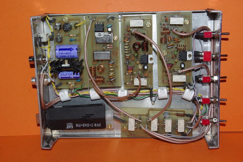
2 External version

3 Although designed for use with the Elonics E4000 tuner it works with any of the available tuners, provided the software you use can control them. The major differences being the maximum receive frequency. Take note that the current rumour is the E4000u tuner is at present not being made and may become scarce with substitutes being supplied. For example the ezcap EzTV668 is still for sale but may be supplied with a different tuner. I have taken a more modular approach in the design so you can build only the boards you want. Also I have included two versions of the power supply - one, a filter, for use in a PC and the other a regulated version for use in an external unit. I have also included a simplified block diagram to make following the design easier.
4 The modules consist of 1. A switching unit with a VHF broadcast band filter 2. A 300 KHz to ~60MHz pre-amplifier of around 18dB gain 3. An HF to VHF converter DC to 60 MHz input up-converted to 125 to 185MHz output 4. A VHF 50MHz to ~2GHz pre-amplifier of up to 18dB gain 5. A PC power rail filter 6. A voltage regulator for an external unit The modules are all stand alone and you just need to build the ones you want and the four major units are built on the same size of PCB to make them easier to fit together in a case. All the units are also designed to use a 12V switching voltage. This is not only to control the relays but also supply the unit, the on-board regulators taking care of the rest. I stated in my previous design that switched mode PSUs are generally not suitable but, in the case of a PC supply, they are usually very well filtered and should not cause major problems. I have, however included a simple PSU filter in the design if needed. The major RF noise source will be the internal PC clocks driving the processor and other internal circuitry. For both the stand alone and PC variants it is very important to build the unit in some form of shielded, preferably earthed, metal enclosure to provide RF screening. Both units are almost identical, with the only major differences being: the external standalone unit has both antenna sockets mounted on the case and a USB lead to connect to an external USB port, the internal unit has flying leads to two BNC sockets mounted on either, an unused expansion slot cover on the back of the PC or, in my case, sockets on the front. The dongle is either plugged into a front USB socket, or to an internal USB lead to either an internal motherboard header or a rear USB socket. The choice is yours, I wired mine as I did because I am still playing with different dongles and antennae.

5 Switching unit and VHF broadcast band filter The switching unit is the only dedicated part of the design and is used to control the signal path through the converter and amplifiers. There is nothing really special in this part of the design with one exception, the VHF broadcast band notch filter. This filter is included to attenuate the VHF broadcast band and in doing so reduce any effect it may have in over-loading the dongle front end, causing de-sensitisation. Further filters may be added if required should any other transmissions cause problems. The filter is just a series tuned resonant circuit across the rf feed rather than the more readily accepted parallel tuned circuit in line thus eliminating any contact resistance and noise effects on the signal. Any contact resistance will only cause a reduction in the filters Q. The details of the coil and relays are shown below. Substitute relays can be used but make sure to use good quality ones. The ones I used were rated for use at up to 2GHz. DC wetting of the contact may improve contact noise performance but was not considered necessary.

6 L1 10 TURNS 3mm ID 0.3 in LONG RELAY Omron Relay G6S-2F-Y 12V (OR SIMILAR)

7 HF pre-amplifier 300 KHz to ~60MHz This can be used as a stand-alone unit with any receiver having a 50 Ohm input impedance. The HF pre-amplifier is designed to have a minimum -3dB frequency of operation of 300KHz with a maximum -3dB point of around 60-65MHz on a 9V supply. The loading coil for the MAR-6 chip is theoretically 84 microh, but, for ease a 100 microh one was used as these are available pre-made, I hate winding coils!. This has the effect of lowering the amplifier minimum frequency. The inclusion of the 60MHz low pass filter helps to eliminate higher frequencies, without it the top frequency could be up to the maximum of the MAR-6. The inclusion of a 3dB pad on the output is to ensure the amplifier sees 50 ohms impedance. Please note I had slight problems with the amplifier using the 100 microh loading coil replacing it with a 4 turn coil on a ferrite bead cured the problems but the minimum operating frequency increased to around 4 MHz, some playing on your part is required here to get the best performance as I tried this on two builds of the amplifier. One needed 4 turns the other 5 for best results. The reason for using a Mar-6 was its excellent low noise figure of 3.0 db or better and its maximum gain of 22dB. I measured mine at around 15-18dB at 10MHz which is reasonable, considering the filter, 3dB pad and relay insertion losses. The 12V control line switches the relays controlling the signal path and supplies the 7809 regulator for the amplifier.


8 1. C2 + C3 115pf TOTAL 2. C4 + C5 164pf TOTAL 3. C6 + C7 164pf TOTAL 4. C8 + C9 115pf TOTAL 5. L1, L2, L3 6.5 TURNS 0.25 in ID 0.4 in LONG 6. Omron Relay G6S-2F-Y 12V (OR SIMILAR)

9 HF to VHF converter This can also be used as a stand-alone unit with any receiver having a 50 Ohm input impedance. The use of the LDO regulator supplying the crystal oscillator module means that although in my complete design it is supplied by 12V it can actually be powered from 5V up to around 20V. This makes it an ideal candidate for powering off the USB bus if you only want to make this module. The HF converter converts the RF signals from DC to 60MHz to an output signal in the range 125 to 185 MHz. Please note it will work with any of the dongles providing the software you are using will drive them. The two clever bits of this design are: the use of a 125MHz local oscillator which means the output signal appears above the VHF broadcast band reducing any effects it has on both sensitivity and desensitisation of the dongle, and, the swapping of the RF and IF ports on the SBL-1 (I used an HPF-505 which is identical) allowing tuning down to DC. The 60MHz low pass filter on the input is there to reject any signals above 60MHz and prevent them from causing problems.

10 1. DC to 60 MHz input up to 125 to 185MHz output 2. C2 + C3 115pf TOTAL 3. C4 + C5 164pf TOTAL 4. C6 + C7 164pf TOTAL 7. C8 + C9 115pf TOTAL 8. L1, L2, L3 6.5 TURNS 0.25 in ID 0.4 in LONG MHz Saronix 3140 or equivalent

11 VHF pre-amplifier This is again another stand-alone unit for use with any receiver having a 50 Ohm input impedance. The VHF pre-amplifier is designed to have a minimum -3dB frequency of operation of 50MHz with a maximum -3dB point of around 2GHz on a 9V supply. The loading coil for the MAR-6 chip is made from a four turn coil wound on a ferrite bead. The inclusion of the 50MHz high pass filter helps to eliminate lower frequencies, without it they could cause interference and de-sensitisation problems. The inclusion of a 3dB pad on the output is to ensure the amplifier sees 50 Ohms impedance. This is particularly important as I have not followed the normal strip-line design method of construction. The reason for using a Mar-6 was again its excellent low noise figure of 3.0 db or better and its maximum gain of 22dB. I measured mine at around 15-18dB at 100MHz, which is reasonable considering the filter, 3dB pad and relay insertion losses. The 12V control line switches the relays controlling the signal path and supplies the 7809 regulator for the amplifier.


12 1. C6 + C2 48 pf TOTAL 2. C3 + C4 45 pf TOTAL 3. C5 + C7 48 pf TOTAL 4. L1, L4 4.5 TURNS 0.25 in ID 0.4 in LONG 5. L2, L3 3.5 TURNS 0.25 in ID 0.3 in LONG 6. L5 4 TURNS on a ferrite bead 7. Omron Relay G6S-2F-Y 12V (OR SIMILAR)

13 Power supplies PC power rail filter This is included for completeness of design, I have not found a need for it on my PC as the internal supply was clean enough to use directly. It is only needed if you have problems. There are no pictures of its build as it is a paper design only. You may have to p[lay with component values to eliminate/minimise any problems from your PC supply. Voltage regulator This is included for completeness of design. I have not built it as I used the internal PC supplies. It is only needed if you use an external supply. There are no pictures of its build as it is a paper design only. You may have to play with component values to eliminate/minimise any problems from your supply. Avoid external switched mode power supplies as they are notorious for being noisy. Summarised hints for use
14 The use of the complete system is relatively straightforward and only the broadest of advice is given as a lot will depend on your antennae and other variables to do with your system. I found my complete system and dongle gave the most sensitivity with the dongle gain set to manual and at a minimum level when using the pre-amplifiers. Turn the dongle gain up slowly till desensitisation starts to occur then back off the gain a little bit. This is the most sensitive setting. In most cases this is more sensitive than the dongle alone. If possible turn off the receiver AGC. This again increases the overall sensitivity. From the performance of my dongle the AGC appears to be audio generated but I could be wrong on this point. Try to use an appropriate antenna on the system with an ATU. This again will give a better signal. I use a long-wire up to around 20MHz and a disk-cone above. This is not ideal as resonant antennas are by far the best particularly as you go up in frequency. Useful Links An article by Brian Benchoff, I first came across this very cheap communications receiver idea on the QRZ forum in a posting by Sue AF6LJ. Please note double check the dongle is compatible. A brief list is at the link below The list of software available includes HDSDR, WINRAD and my personal favourite, SDR Sharp The site takes a little bit of exploring to find everything but is well worth the effort as at present I have not found any problems and the people running the site and writing the software seem to be very approachable for help and advice. Just make sure you download the latest version. See my posting on the radio board for further details at: The idea of a receive converter was, I believe, first broached by George (M1GEO) / and Chris (G8OCV) on Mar amplifer design document Filter design programme
15 Any comments will be gratefully received and as usual I can be contacted by at n.strong@hotmail.co.uk or via the Radio Board and QRZ forums as G0CWA. I cannot guarantee to see your questions if posted elsewhere REMEMBER TO CHECK THE PCB TRACK LAYOUTS AND MIRROR THEM IF NEEDED. I HAVE PRESENTED THEM AS X-RAY VIEWS OF THE FINAL BOARD!!!! A SIMPLE WAY TO MOUNT ANY SURFACE MOUNT COMPONENTS ON A SINGLE SIDED PCB IS TO SOLDER A VERO PIN THROUGH THE BOARD. THE PIN HEAD MAKES A SMALL PAD TO SOLDER COMPONENTS TO ON THE COMPONENT SIDE. All the best for now and happy building de G0CWA (Nick) PLEASE NOTE if you downloaded this document from anywhere but or I can not guarantee you will have the latest version, Please inform Dave if it was downloaded from another site. Daves site is the ONLY ONE I HAVE AUTHORISED to distribute/display my projects and documents. However links to the projects are permitted with Daves permission.
GRID DIP METER DESIGN
 GRID DIP METER DESIGN BY G0CWA MAY 2013 This, my next offering of test equipment is an exceptionally useful item of test equipment with many uses, some are listed below. To coin a phrase given to me by
G0CWA ANALOG AF/MF SIGNAL GENERATOR APRIL 2013
 G0CWA ANALOG AF/MF SIGNAL GENERATOR APRIL 2013 INTRODUCTION Hi here is my design for a simple easily customizable signal generator generating variable levels of sin, triangular and square wave signals
MARTIN - G8JNJ ECLECTIC AETHER - ADVENTURES WITH AMATEUR RADIO
 MARTIN - G8JNJ ECLECTIC AETHER - ADVENTURES WITH AMATEUR RADIO REDUCING RTL DONGLE INTERNAL SPURII AND NOISE SIGNALS I ve recently bought quite a few RTL DVB-T RTL 2832U / Rafael Micro R820T dongles to
by Cliff Pulis, KE0CP SDR Presentation - Cliff Pulis, KE0CP 1
 by Cliff Pulis, KE0CP SDR Presentation - Cliff Pulis, KE0CP 1 Basic Receiver Principles Mixing Frequencies Hetrodyn ing The IF Amplifier SDR Principles & Quadrature Phase (IQ) VHF / UHF DVB-T Dongle SDR
FC3 Project Info: PIC18F /500MHZ Frequency Counter & RF Meter. This project is developed for Amateur Radio Community by:
 Fox Delta Amateur Radio Projects & Kits FC3-0915 FC3 Project Info: PIC18F4550 50/500MHZ Frequency Counter & RF Meter This project is developed for Amateur Radio Community by: Antonio Alfinito / I2TZK Dinesh
Antenna Matching Within an Enclosure Part II: Practical Techniques and Guidelines
 Antenna Matching Within an Enclosure Part II: Practical Techniques and Guidelines By Johnny Lienau, RF Engineer June 2012 Antenna selection and placement can be a difficult task, and the challenges of
144MHz direct conversion receiver with I/Q outputs for use with Software Defined Radio.
 144MHz direct conversion receiver with I/Q outputs for use with Software Defined Radio. Overview This design is a direct conversion receiver for 144MHz with quadrature outputs for use either with a software
HF Amateur SSB Receiver
 HF Amateur SSB Receiver PCB Set for radio club project http://rhelectronics.net PCB for DIY HF Amateur SSB Receiver 20M The receiver is a simple syperheterodyne type with quartz crystal filter. The circuit
Preliminary features of the SDR-X receiver SDR-X , PowerSDR Winrad Winrad DDS SFDR SFDR AD995 AD99 1
 Preliminary features of the SDR-X receiver The SDR-X receiver, in its full version is capable of continuously tuning the entire HF spectrum, 6m ( 50-52 MHz) band included. SSB, AM etc. demodulation, bandpass
PCS Electronics
 PCS Electronics www.pcs-electronics.com info@pcs-electronics.com µmax ST-1 High Performance Stereo Encoder With Easy RDS Upgrade Option µmax ST-1 stereo encoder with XLR balanced audio inputs This is our
ATUs - ANTENNA TUNING UNITS THE ATU. An Antenna Tuning Unit MAKE YOUR OWN ATU
 ATUs - ANTENNA TUNING UNITS THE ATU An Antenna Tuning Unit MAKE YOUR OWN ATU The circuit diagram below shows the circuit for a typical Pi type ATU which seems to be a popular arrange ment for many ATUs.
The K290R Project. Steve Kavanagh, VE3SMA, December 2017
 The K290R Project Steve Kavanagh, VE3SMA, December 2017 Background I have been using a pair of Yaesu FT-290R 2m transceivers as IF rigs for microwave transverters for many years. My 2.3, 3.4, 5.7, 10 and
Overview of the MSA 12/30/10
 Overview of the MSA 12/30/10 Introduction The purpose of this document is to provide an overview of the capabilities and construction of the MSA to help potential builders get oriented. Much more detailed
AfedriNet Review. SDRZone. AfedriNet SDR Review
 AfedriNet Review SDRZone AfedriNet SDR Review December 31st 2013 Reviewed by NI0Z AFEDRI SDR-Net http://www.afedri-sdr.com/ Downloads & Manuals http://www.afedri-sdr.com/index.php/downloads AFEDRI SDR-Net
and RTL-SDR Wireless Systems
 Laboratory 4 FM Receiver using MATLAB and RTL-SDR Wireless Systems TLEN 5830 Wireless Systems This Lab introduces the working of FM Receiver using MATLAB and Software Defined Radio This exercise encompasses
Interference & Suppression Page 59
 INTERFERENCE Interference & Suppression Page 59 Front-End Overload, Cross-Modulation What is meant by receiver overload? Interference caused by strong signals from a nearby transmitter What is one way
87415A microwave system amplifier A microwave. system amplifier A microwave system amplifier A microwave.
 20 Amplifiers 83020A microwave 875A microwave 8308A microwave 8307A microwave 83006A microwave 8705C preamplifier 8705B preamplifier 83050/5A microwave The Agilent 83006/07/08/020/050/05A test s offer
Single Conversion LF Upconverter Andy Talbot G4JNT Jan 2009
 Single Conversion LF Upconverter Andy Talbot G4JNT Jan 2009 Mark 2 Version Oct 2010, see Appendix, Page 8 This upconverter is designed to directly translate the output from a soundcard from a PC running
A 75-Watt Transmitter for 3 Bands Simplified Shielding and Filtering for TVI BY DONALD H. MIX, W1TS ARRL Handbook 1953 and QST, October 1951
 A 75-Watt Transmitter for 3 Bands Simplified Shielding and Filtering for TVI BY DONALD H. MIX, W1TS ARRL Handbook 1953 and QST, October 1951 The transmitter shown in the photographs is a 3-stage 75-watt
SDR 4++ Dual Diversity SDR Receiver. Operating Guide. version 1.0
 Cross Country Wireless, 7 Thirlmere Grove, BOLTON, BL4 0QB, UK Email chrism@crosscountrywireless.net Web page http://www.crosscountrywireless.net Telephone +44 (0) 1204 410626 Mobile / Workshop +44 (0)
5000 Series Receiver Systems
 5000 Series Receiver Systems Modular multi-channel receiver system for demanding musical and broadcast applications Large mainframe houses up to 8 true diversity receiver modules Small mainframe houses
Written by Chris Kepus, W7JPG; installation test results and comments by Terry Wagoner, K9TW.
 Collins 500 Hz filter sub for Kenwood YG-455C - TS-830S Written by Chris Kepus, W7JPG; installation test results and comments by Terry Wagoner, K9TW. My TS-830S was in need of a significant amount of work
Elecraft EC1 Design Contest Entry
 Elecraft EC1 Design Contest Entry The following is an Elecraft EC1 design contest entry from Joe Loritz, N9ZIA. Design Overview This design is a low cost, easy to homebrew, 100-900 MHz antenna analyzer.
PCB Design Guidelines for GPS chipset designs. Section 1. Section 2. Section 3. Section 4. Section 5
 PCB Design Guidelines for GPS chipset designs The main sections of this white paper are laid out follows: Section 1 Introduction Section 2 RF Design Issues Section 3 Sirf Receiver layout guidelines Section
Low Distortion Mixer AD831
 a FEATURES Doubly-Balanced Mixer Low Distortion +2 dbm Third Order Intercept (IP3) + dbm 1 db Compression Point Low LO Drive Required: dbm Bandwidth MHz RF and LO Input Bandwidths 2 MHz Differential Current
HOMEBREW Q-MULTIPLIER
 HOMEBREW Q-MULTIPLIER This circuit can boost the signal strength in your receiver by 1 or 2 S-units, giving approximately 10 db gain. A Q-multiplier amplifies the Q of the first IF transformer so that
Technical Manual For Chips Multilayer Antenna Matching Adjustment Method LDA31 series
 Technical Manual For Chips Multilayer Antenna Matching Adjustment Method LDA31 series Application: 2.4GHz Wireless Bluetooth TM 1/17 Chip Antenna is a special component to change characteristics and this
SPECIFICATIONS: Subcarrier Frequency 5.5MHz adjustable, FM Modulated +/- 50KHz. 2nd 11MHz >40dB down from 5.5MHz
 Mini-kits AUDIO / SUBCARRIER KIT EME75 Version4 SPECIFICATIONS: Subcarrier Frequency 5.5MHz adjustable, FM Modulated +/- 50KHz Subcarrier Output 1.5v p-p Output @ 5.5MHz DESCRIPTION & FEATURES: The Notes
12kHz LIF Converter V2.43 9Mhz version
 12kHz LIF Converter V2.43 9Mhz version Please Note: This document supersedes all previously released documents and drawings on the LIF subject. This is the latest and most up-to-date document at this time.
PRODUCTS BROCHURE PRODUCTS OVERVIEW
 PRODUCTS BROCHURE WELCOME TO MOUNTAIN RF Mountain RF Sensors is engaged in the design and manufacture of specialty radio frequency (RF) products for government and military customers. The company is geared
But this is about practical experiments so lets find out what an inductor is all about.
 Chapter 2 inductors Inductors are components we often use in radio design. We measure them with our LCR meter and build a circuit with them, only to find out the resonance is way off from the calculated
Construction Manual 4m-Linear-Transverter XV4-15
 Construction Manual 4m-Linear-Transverter XV4-15 Holger Eckardt DF2FQ Kirchstockacherstr. 33 D-85662 Hohenbrunn 3207 Technical data exciter frequency: 21.0... 21.5 MHz RF frequency: 70.0.. 70.5 MHz supply
Using a Software Defined Radio As a Panadapter
 Using a Software Defined Radio As a Panadapter by Dave Core, K8WDA Presented to the Northern Kentucky Amateur Radio Club by Dave Core, K8WDA, on Oct. 9, 2017. What Is a Panadapter? Panadapter aka: Panoramic
Balanced Line Driver & Receiver
 Balanced Line Driver & Receiver Rod Elliott (ESP) Introduction Sometimes, you just can't get rid of that %$#*& hum, no matter what you do. Especially with long interconnects (such as to a powered sub-woofer),
Handy dandy little circuit #17 #17
 Handy dandy little circuit #17 #17 Download # 17 in PDF There are a lot of alarm systems on the market but you might be inclined to build your own. This little project can be put together using inexpensive
1.0 General Description
 1.0 General Description Figure 1 Plug-N-Play Noise Blanker for the Collins KWM-2/2A The Collins Noise Blanker is designed to be a Plug-N-Play accessory for the Collins KWM-2/2A transceivers. It plugs directly
SE4 DSP + High Performance Professional Digital Stereo Encoder With DSP Filters
 PCS Electronics www.pcs-electronics.com info@pcs-electronics.com SE4 DSP + High Performance Professional Digital Stereo Encoder With DSP Filters SE4 DSP + without the LCD control module (connects to black
1 of 11 30/08/2011 8:50 AM
 1 of 11 30/08/2011 8:50 AM All Ferrite Beads Are Not Created Equal - Understanding the Importance of Ferrite Bead Material Behavior August 2010 Written by Chris Burket, TDK Corporation A common scenario:
A SDR-based receiver for Es hail-2 and the BACAR 6, 10 GHz beacons 30 July 2018
 A SDR-based receiver for Es hail-2 and the BACAR 6, 10 GHz beacons 30 July 2018 Hannes Coetzee, ZS6BZP Introduction If all goes according to plan the Qatar Satellite Company (Es hailsat) will place its
Improving the immunity of sensitive analogue electronics
 Improving the immunity of sensitive analogue electronics T.P.Jarvis BSc CEng MIEE MIEEE, I.R.Marriott BEng, EMC Journal 1997 Introduction The art of good analogue electronics design has appeared to decline
The 15 meter section was moved
 After 2 years or so making various adjustments to the original LPF filter configuration, and noting some of the changes which could be made to the board to make it easier to construct, tune, and reconfigure
SWL Receiving Antenna Experiments
 SWL Receiving Antenna Experiments Introduction I have a lot to learn about SWL antennas. What follows are some brief experiments I performed in late October 2005. I have been experimenting with a half
N3ZI Kits General Coverage Receiver, Assembly & Operations Manual (For Jun 2011 PCB ) Version 3.33, Jan 2012
 Version 3.33, Jan 2012") N3ZI Kits General Coverage Receiver, Assembly & Operations Manual (For Jun 2011 PCB ) Version 3.33, Jan 2012 Thank you for purchasing my general coverage receiver kit. You can use the photo above as a
N3ZI Kits General Coverage Receiver, Assembly & Operations Manual (For Jun 2011 PCB ) Version 3.33, Jan 2012 Thank you for purchasing my general coverage receiver kit. You can use the photo above as a
Electromagnetic interference at the mains ports of an equipment
 Electromagnetic interference at the mains ports of an equipment Mircea Ion Buzdugan, Horia Bălan, Emil E. Simion, Tudor Ion Buzdugan Technical University from Cluj-Napoca, 15, Constantin Daicoviciu street,
Alcatel White Box 24GHz Transceiver experiments and modifications
 Alcatel White Box 24GHz Transceiver experiments and modifications A set of working notes, measurements and comments PSU Need to supply : -5V up to ~ 30mA for Rx and PA modules +5.2V 1A for Rx and Tx mixer
ICOM IC-7200 Military
 DG2IAQ Modification notes 20-Jul-2003, rev. 21. Feb. 2009 / p. 1 The famous ICOM IC-7200 is a great transceiver and I like it very much. As announced in several forums I realized that it has some (few)
Step by Step Building PJ meter ARDF Receiver Kit. CRKITS.COM August 5, 2013
 Step by Step Building PJ-80 80-meter ARDF Receiver Kit CRKITS.COM August 5, 2013 What is ARDF? ARDF is the abbreviation of Amateur Radio Direction Finding, or so called Fox Hunting. If you are looking
RSP family of Full Featured Wideband SDR Receivers
 RSP family of Full Featured Wideband SDRuno SDR receivers What is an SDR? A radio communication system where components that have been traditionally implemented in hardware (e.g. mixers, filters, amplifiers,
Take another look at the Noise Bridge:
 Take another look at the Noise Bridge: Author K.P.Barnsdale ZL3KB Date 21 October 1998 Diagrams: 1. Circuit diagram. 2. PCB layout 3. Front panel layout 4. Internal layout diagram 5. Inductance chart Introduction
Yaesu FT-1000MP Mark V and NaP3
 Yaesu FT-1000MP Mark V and NaP3 This paper describes in detail the hardware and software required to implement a full-function panadaptor for the Mark V using NaP3. Illustration 1: Panadaptor in operation
THE INTERMEDIATE VFO
 THE INTERMEDIATE VFO Some Intermediate tutors have reported difficulties in either obtaining parts for the RSGB Intermediate textbook VFO or in getting the VFO going once they have the parts. This alternative
PCS Electronics
 PCS Electronics www.pcs-electronics.com info@pcs-electronics.com µmax RM-1 RDS encoder plug-in upgrade for PCI MAX 2006+ and ST-1 µmax ST-1 µmax RM-1 (pronounced micro max RM-1) is a simple plug-in board
Model AAA-1C. Addendum to AAA-1B documentation
 Model AAA-1C. Addendum to AAA-1B documentation 1. Specifications for Model AAA-1C (11) General Output impedance Power supply (1) Maximal output voltage (10) Physical size 50 Ohms, BNC connector on control
HT-1A Dual Band CW QRP Transceiver. Kit Building Instructions
 HT-A Dual Band CW QRP Transceiver Kit Building Instructions Rev B, July 8, 08 Designed by BD4RG Exclusively distributed by CRKITS.COM and its worldwide distributors Join the group http://groups.io/g/crkits
KN-Q10 Assembly Manual
 KN-Q10 Assembly Manual Translated by Adam Rong, BD6CR/4 with permission from Ke Shi, BA6BF Edited by Stephen, VK2RH Revision B, Oct 14, 2010 Thank you for purchasing the KN-Q10 4 Band SSB/CW Dual Mode
SX1261/2 WIRELESS & SENSING PRODUCTS. Application Note: Reference Design Explanation. AN Rev 1.1 May 2018
 SX1261/2 WIRELESS & SENSING PRODUCTS Application Note: Reference Design Explanation AN1200.40 Rev 1.1 May 2018 www.semtech.com Table of Contents 1. Introduction... 4 2. Reference Design Versions... 5 2.1
Homebrew and Experimenters Group HF Inductance Bridge (Compiled by VK2TOX)
") Homebrew and Experimenters Group HF Inductance Bridge (Compiled by VK2TOX) There are a number of ways to measure inductances used in construction of RF equipment. One of the most versatile ways is with
Homebrew and Experimenters Group HF Inductance Bridge (Compiled by VK2TOX) There are a number of ways to measure inductances used in construction of RF equipment. One of the most versatile ways is with
Research White Paper WHP 164. Portable Receivers for Digital Radio Mondiale: A Look at Antennas and Sensitivities BRITISH BROADCASTING CORPORATION
 Research White Paper WHP 164 May 2008 Portable Receivers for Digital Radio Mondiale: A Look at Antennas and Sensitivities R H M Poole BRITISH BROADCASTING CORPORATION BBC Research White Paper WHP 164
10 GHz Microwave Link
 10 GHz Microwave Link Project Project Objectives System System Functionality Testing Testing Procedures Cautions and Warnings Problems Encountered Recommendations Conclusion PROJECT OBJECTIVES Implement
Building and Operating: LF Converter An SA612 based LF up-converter from Jackson Harbor Press
 Introduction: Building and Operating: LF Converter An SA612 based LF up-converter from Jackson Harbor Press The frequencies below the broadcast band are covered by few receivers on the market - those that
PART MAX2605EUT-T MAX2606EUT-T MAX2607EUT-T MAX2608EUT-T MAX2609EUT-T TOP VIEW IND GND. Maxim Integrated Products 1
 19-1673; Rev 0a; 4/02 EVALUATION KIT MANUAL AVAILABLE 45MHz to 650MHz, Integrated IF General Description The are compact, high-performance intermediate-frequency (IF) voltage-controlled oscillators (VCOs)
Connecting the FCC-2 to the Hendricks DC Kits Bob Okas, W3CD
 Connecting the FCC-2 to the Hendricks DC Kits Bob Okas, W3CD This is an application note that describes how you can connect the NorCal FCC-1/2 combination to the DC kits. It involves a few extra components
Yana Dongles Tom Berger K1TRB (c)2016 v171227
2016 v171227") Yana Dongles Tom Berger K1TRB (c)2016 v171227 These notes elaborate some items described in the Build notes, and add some more dongles enhancing Yana. Every effort has been exerted to save on the cost
Yana Dongles Tom Berger K1TRB (c)2016 v171227 These notes elaborate some items described in the Build notes, and add some more dongles enhancing Yana. Every effort has been exerted to save on the cost
Swr Analyzer Foxdelta
 Swr Analyzer Foxdelta 1 / 6 2 / 6 3 / 6 Swr Analyzer Foxdelta SWR ANALYZER v6.00 by Tony, i2tzk Page. Connect the SWR Analyzer Unit to the PC or Laptop using a standard USB cable (printer cable), after
Transceiver selection and Specs.
 Transceiver selection and Specs. Transceivers 1956-2018 From TUBES to SDR Covers 20-10 meters in 100Khz segments, 10 available, crystal needed for each. Plug in crystal holder. 100 Watts output, final
Reviewed. SWR analyser
 December 2011 3.50 ISSN 0141-0857 NOW IN ITS 79th YEAR! Reviewed Wouxun KG-UVD1PL 70/144MHz Dual-band hand-held transceiver YouKits FG-01 SWR analyser Practical Way Radios for children Antennas Whispering
A 100-Watt Transmitter Using a Pair of VT1625s
 12/16/2007 6:00 PM VT1625 100 Watt Transmitter A 100-Watt Transmitter Using a Pair of VT1625s FIG. 10.6 A 100-watt transmitter for five bands, using salvaged TV power transformer and surplus 1625 amplifier
71MHz RB-DATV Getting Started on the new Band. Shaun O Sullivan G8VPG
 71MHz RB-DATV Getting Started on the new Band Shaun O Sullivan G8VPG 70.5-71.5MHz New 4m allocation 100W ERP maximum power 20m maximum aerial height Annual NoV from RSGB for full licensees Maximum channel
DC Injector (Bias Tee) kit. Technical Manual
 kit. Technical Manual") DC Injector (Bias Tee) kit Technical Manual Document Author Dave Powis, G4HUP Date 7 Jan 2017 Version Issue 2_0 Document Ref HUP-05-020 http://huprf.com Tel +44 (0)1473 737717 g4hup@outlook.com Contents
DC Injector (Bias Tee) kit Technical Manual Document Author Dave Powis, G4HUP Date 7 Jan 2017 Version Issue 2_0 Document Ref HUP-05-020 http://huprf.com Tel +44 (0)1473 737717 g4hup@outlook.com Contents
Ensemble RXTX 07_RX Opamps and Output
 Page 1 of 10 Ensemble RXTX 07_RX Opamps and Output Home Bill of Materials Power Supply USB Power Supply Local Oscillator Dividers RF I/O and Switching RX Mixer (QSD) RX Opamps and Output TX Opamps TX Mixer
Developing a 1296 MHz Beacon. By Kevin Murphy ZL1UJG April 2009
 Developing a 1296 MHz Beacon By Kevin Murphy ZL1UJG April 2009 1 Stage Functions Oscillator Module Multiplier Module Amplifier Module Keyer PSU Module Circulator/Filter 2 A good start for an oscillator
COMM 704: Communication Systems
 COMM 704: Communication Lecture 1: Introduction Dr. Mohamed Abd El Ghany, Mohamed.abdel-ghany@guc.edu.eg Course Objective Give an introduction to the basic concepts of electronic communication systems
Television and video engineering
 Television and video engineering Unit-4 Television Receiver systems Objectives: To learn the requirements of TV receiver Study of monochrome and Colour TV receivers. To learn functions of Tuning circuits
Software Defined Radio in Ham Radio Dennis Silage K3DS TS EPA Section ARRL
 Software Defined Radio in Ham Radio Dennis Silage K3DS silage@arrl.net TS EPA Section ARRL TUARC K3TU SDR in HR The crystal radio was once a simple introduction to radio electronics and Amateur Radio.
Technical Info Doc: Galileo2 A simple Direct Conversion Receiver for 20.1MHZ
 Fox Delta Amateur Radio Projects & Kits FD Galileo2 Technical Info Doc: Galileo2 A simple Direct Conversion Receiver for 20.1MHZ This Project is dedicated to our beloved scientist Galileo: Galileo was
SHF Communication Technologies AG. Wilhelm-von-Siemens-Str. 23D Berlin Germany. Phone Fax
 SHF Communication Technologies AG Wilhelm-von-Siemens-Str. 23D 12277 Berlin Germany Phone ++49 30 772 051-0 Fax ++49 30 753 10 78 E-Mail: sales@shf.de Web: http://www.shf.de Datasheet SHF D836 A Differential
CUTTING THROUGH... RADIO INTERFERENCE
 Aussi disponible en français. 32-EN-95539W-01 Minister of Supply and Services Canada 1996 CUTTING THROUGH... RADIO INTERFERENCE THE COMMUNICATIONS AGE In recent years, the proliferation of transmitters,
Modifying The Heath HA-14 For 6 Meters Greg Chartrand - W7MY 4/22/07
 Introduction The Heathkit HA-14 was one of the few electron tube linear amplifiers intended for mobile use but few were purchased with the 12 volt mobile power supply. Most hams bought the HA-14 for base
L AND S BAND TUNABLE FILTERS PROVIDE DRAMATIC IMPROVEMENTS IN TELEMETRY SYSTEMS
 L AND S BAND TUNABLE FILTERS PROVIDE DRAMATIC IMPROVEMENTS IN TELEMETRY SYSTEMS Item Type text; Proceedings Authors Wurth, Timothy J.; Rodzinak, Jason Publisher International Foundation for Telemetering
Improved Ionospheric Propagation With Polarization Diversity, Using A Dual Feedpoint Cubical Quad Loop
 Improved Ionospheric Propagation With Polarization Diversity, Using A Dual Feedpoint Cubical Quad Loop by George Pritchard - AB2KC ab2kc@optonline.net Introduction This Quad antenna project covers a practical
Fox Delta FC Amateur Radio Projects & Kits. FC3 Project Info: PIC18F /500MHZ Frequency Counter & RF Meter
 Fox Delta Amateur Radio Projects & Kits FC3-0812 FC3 Project Info: PIC18F4550 50/500MHZ Frequency Counter & RF Meter This project is developed for Amateur Radio Community by: Antonio Alfinito / I2TZK Dinesh
Custom Integrated Circuit (MSM9520RS) Replacement Module
 Replacement Module") FT-101Z/ FT-107/ FT-707/ FT-901,902 (later version) DISPLAY COUNTER UNIT (PB-2086A) Custom Integrated Circuit (MSM9520RS) Replacement Module Assembly and Installation Manual (v1.3e) STEP-BY-STEP PROCEDURES
FT-101Z/ FT-107/ FT-707/ FT-901,902 (later version) DISPLAY COUNTER UNIT (PB-2086A) Custom Integrated Circuit (MSM9520RS) Replacement Module Assembly and Installation Manual (v1.3e) STEP-BY-STEP PROCEDURES
DEM Part Number L144-28INTCK 144 MHz Transverter Kit and complete kit
 DEM Part Number L144-28INTCK 144 MHz Transverter Kit and complete kit Power Out: Noise Figure and Gain: DC Power Requirement: 50 mw linear minimum 3.5 db NF nominal, 5 dbg maximum 12-15.5 VDC, 13.8 nominal
Manufacturers of RF and Microwave Components and Assemblies Specialist in RF Filters, Power amplifiers and RF Switches
 Manufacturers of RF and Microwave Components and Assemblies Specialist in RF Filters, Power amplifiers and RF Switches sales@cormic.com www.cormic.com P 724.940.7556 F 724.940.7707 RF & MICROWAVE FILTERS
DATA SHEET. TSA5515T 1.3 GHz bi-directional I 2 C-bus controlled synthesizer INTEGRATED CIRCUITS
 INTEGRATED CIRCUITS DATA SHEET TSA5515T 1.3 GHz bi-directional I 2 C-bus controlled synthesizer File under Integrated Circuits, IC02 November 1991 GENERAL DESCRIPTION The TSA5515T is a single chip PLL
13.56MHz Antennas APPLICATION-NOTE. OBID i-scan. Construction and tuning of 13.56MHz antennas for Reader power levels up to 1W
 OBID i-scan APPLICATION-NOTE 13.56MHz Antennas Construction and tuning of 13.56MHz antennas for Reader power levels up to 1W final public (B) 2003-01-15 N20901-2e-ID-B.doc Note Copyright 2002 by FEIG ELECTRONIC
Copyright 2012, R. Eckweiler & OCARC, Inc. Page 1 of 5
 Heathkit of the Month #42: by Bob Eckweiler, AF6C Heathkit HD-1422-A Antenna Noise Bridge Introduction: If you work with antennas, an antenna noise bridge can be a very handy tool. Table 1 lists some of
Application note and implementation guideline OnBoard SMD 434 MHz
 Page 1 Rev 1.4 Application note and implementation guideline OnBoard SMD 434 MHz Patent: SE537042 + Pending Page 2 Rev 1.4 Table of contents 1. General... 3 2. Intended applications... 3 3. Technical data...
COAXIAL TRANSMISSION LINE COMMON-MODE CURRENT
 COAXIAL TRANSMISSION LINE COMMON-MODE CURRENT Introduction Coaxial transmission lines are popular for their wide frequency bandwidth and high resistance to electromagnetic interference (EMI). Coax cables
Categorized by the type of core on which inductors are wound:
 Inductors Categorized by the type of core on which inductors are wound: air core and magnetic core. The magnetic core inductors can be subdivided depending on whether the core is open or closed. Equivalent
Active Antennas 4/28/2017
 1 Active Antenna??? What Why Theory Loops Verticals Dipoles Amplifier Considerations VE7KW experiments 2 What Simply an antenna with an amplifier - Automotive application - My first exposure to active
Amateur Radio Examination EXAMINATION PAPER No. 275 MARKER S COPY
 01-6-(d) An Amateur Station is quoted in the regulations as a station: a for training new radio operators b using amateur equipment for commercial purposes c for public emergency purposes d in the Amateur
AN4819 Application note
 Application note PCB design guidelines for the BlueNRG-1 device Introduction The BlueNRG1 is a very low power Bluetooth low energy (BLE) single-mode system-on-chip compliant with Bluetooth specification
The 144MHz Anglian 3 transverter
 The 144MHz Anglian 3 transverter A high performance 144/28MHz transverter G4DDK document issue 1 12/9/16 Introduction Anglian 3 is an update to the 144MHz Anglian 2 transverter. The Anglian 2 is no longer
OnBoard SMD WLAN antenna
 Application note and implementation guideline OnBoard SMD WLAN antenna Patent: SE537042 + Pending rev 1.2 Proant AB 1 Table of contents 1. General... 3 2. Intended applications... 3 3. Technical data...
An Oscillator Scheme for Quartz Crystal Characterization.
 An Oscillator Scheme for Quartz Crystal Characterization. Wes Hayward, 15Nov07 The familiar quartz crystal is modeled with the circuit shown below containing a series inductor, capacitor, and equivalent
DIY: from vinyl to compact disk
 AUDIO & HI-FI DIY: from vinyl to compact disk with a PC and sound card Nowadays, with the availability of personal computers and compact-disk (CD) writers, there is nothing in the way of transferring one
The Future of Sound. Made Perfectly Clear.
 JK DI-Boxes User Guide JK1 - Active DI BOX JK2 - Stereo DI BOX JKA - Acoustic DI BOX JKP - Passive DI BOX JKT - Tone Generator The Future of Sound. Made Perfectly Clear. At KV2 Audio our vision is to constantly
tuning and RF circuits wireless automotive inductors inductance (L). Now frequencies
. Now frequencies") RF Chip Inductor Applications December 2011 Application Note RF chip are an integral part of many tuning and filtering circuits and are mainly used in the RF circuits in electronics systems. With a small
RF Chip Inductor Applications December 2011 Application Note RF chip are an integral part of many tuning and filtering circuits and are mainly used in the RF circuits in electronics systems. With a small
VLF-LF-MF Up Converter
 VLF-LF-MF Up Converter 5kHz-500kHz 3.5MHz-4MHz model 350 4MHz-4.5MHz model 400 User manual. Rev 2018-01 Since many countries are allocating the 472 khz to 479kHZ band for experimental use by Radio Amateurs,