2015 Northwest Electric Meter School. A division of Brayden Automation Corp. Introduction to Pulse Metering, Pulse Initiators & Isolation Relays
|
|
|
- Sydney Barnett
- 6 years ago
- Views:
Transcription


1 2015 Northwest Electric Meter School A division of Brayden Automation Corp. Introduction to Pulse Metering, Pulse Initiators & Isolation Relays August 25, 2015 By William H. Brayden, President Brayden Automation Corp./Solid State Instruments Loveland, CO Overview Pulse Metering Terms and Definitions Pulse Calculations Pulse Initiators and Configurations Pulse Applications Pulse Isolation Relays 1
 Switch and Relay Forms What is")


2 Terms & Definitions Pulse Metering Pulse Pulse Initiator Pulse Constant Ke, PKe, Kh, Kp, Kd, Mp CT Ratio, PT Ratio, Multiplier (TF) Switch and Relay Forms What is Pulse Metering? Pulse Metering is the act of measuring energy usage with a watt hour meter, then converting the measured quantity into electronic increments of a constant known value, known as pulses. Filling & dumping a bucket analogy Common standard of exchanging energy use information between systems Simple and Non proprietary 2
3 What is Pulse Metering? Fundamentally used for two purposes: 1. Counting pulses for energy consumption (Kwh) 2. Timing pulses for determining demand KW = (kilowatt hours X3600) seconds KW = kilowatt seconds seconds Why use Pulse Metering? Two general purposes of pulses: 1.) Interval Data Pulses were the basis for counting and recording usage 2.) Real Time Power Use A method of transferring instantaneous real time energy usage information to other devices without any direct electrical contact 3
4 Why use Pulse Metering? Interval Data uses: Customer Billing 1. Energy charges 2. Demand charges 3. Power Factor charges 4. Load Factor Average Demand/ Peak Demand TOU Rate Studies 1. Survey of energy during specific periods to determine the effect of TOU rate structures. 2. Comparing electric heat to gas usage on apartments Why use Pulse Metering? System Planning 1. Future load growth projections 2. Transformer sizing 3. Assisting with rate structures 4. Load projections Future consideration for substation, transmission construction Customer satisfaction and retention 1. Offering more Services, Real Time Pricing 2. Answering billing questions 3. Reduce their energy costs 4
5 Why use Pulse Metering? Utility Applications 1. Delivering pulses to multiple systems (Wholesale Delivery points) for system control 2. Load Profile Information collection using pulses with external pulse recorder 3. Totalization, Billing & Support of special rate structures 4. Check meter comparison with counting/totalizing register relay 5. AMR Automated Meter Reading meter interface Why use Pulse Metering Customer Applications 1. Energy Management / Demand Control Energy Pulses * End of Interval Pulse TOU Pulse Power Factor Calculation 2. Sub metering 3. To combine meter data with other quantities like inputs from gas, water, temperature, pressure, flow, etc. for Energy Tracking. 4. Pulses can be thought of as the lowest common denominator of instantaneous energy information. Reading pulses is generally universal in the EMS industry. Non proprietary. 5
6 What is a Pulse? In Pulse Metering, Form C (3 wire) Pulse A pulse is defined as the change of state or a transition of the pulse initiator from one state to the opposite state. Toggle Form A (2 wire) Pulse a pulse is a complete cycle of a on state transition, a dwell time, and then transition returning to the off state. Momentary What is a Pulse? Momentary contact closures are normally associated with 2-wire (Form A) systems Toggle closures are normally associated with 3-wire (Form C) systems. 6
7 What is a Pulse? A pulse is directly related to a programmable defined value Ke in solid state meters, or to a disk revolution (Kh) in induction meters. Units are in kilowatt hours or watt hours a pulse represents ENERGY (kwh,kvah,kvarh,etc). Pulses can be generated: mechanically (gears &, cams), optically (reflective, through hole), electronically, (hall effect) semiconductor devices (most common today) NEMA Standard EI 13 A Pulse is an electrical signal which departs from an initial level for a limited duration of time and returns to the original level. (This is incorrect for Form C pulses) Example: A sudden change in voltage or current produced by the opening or closing of a contact. Examples: Handbook for Electricity Metering Closing a two wire (Form A) contact SPST Switch Model Closing one side of a three wire (Form C) contact and simultaneously opening the opposite side SPDT Switch Model 7

8 NEMA Standard EI 13 Pulse devices for electricity metering are the functional units for initiating, transmitting, retransmitting, or receiving electric pulses, representing finite quantities, such as energy, normally transmitted from some form of electricity meter to a receiver unit. Handbook for Electricity Metering NEMA Standard EI 13-1 A pulse initiator is any device, mechanical or electrical, used with a meter to initiate pulses, the number of which is proportional to the quantity being measured. It may include an external amplifier, an auxiliary relay, or both to change the amplitude or waveform of a pulse for re transmission to another pulse device. 8
9 What is a Ke Value? Ke is a representation of the amount of energy (at the pulse generator) in an electronic meter. Generally expressed in kilowatt hours per pulse. Ke value is programmable Example: Ke =.001kwh or 1 wh pulse pulse Also called the Secondary Pulse Constant or Energy Constant Ke assumes 120VAC/5A at the meter Ke does not include the CT*PT multiplier of the customer s metering application. What is Pke? Pke is the Primary Pulse Constant. Also called Final Ke or Ke (final) Pke includes the CT*PT multiplier Pke =Ke X(CT * PT) Pke represents the actual energy (Kwh) consumed per pulse in a specific customer metering application. 9
10 Calculating the Pke Value Example: Given: 120/208VAC service Ke =.001 CTR= 600A:5A = 120 PTR= 1 Pke = Ke X(CT x PT) *or the actual energy value per pulse which is: Pke =.001 Kwh X (120X1) =.120 kwh/pulse or 120 wh/p What is the Pke Value? Some Meter Manufacturers do this differently: Given: 120/208VAC service Kh = 1.8 wh/rev P/R(virtual) = Programmable (default = 24) CTR = 600A:5A = 120 PTR = 1 Pke = KhX(CT*PT) P/R *or the actual energy value per pulse which is: Pke = 1.8/24 X 120 = 9.0 wh/pulse or.009 kwh/p 10
 Ke =. 032 /160 Ke =.")
11 How to Set the Ke Value (working backwards) Suppose: Customer requires 32 wh/p 120/208VAC so PTR = 1 CTR = 800A:5A = 160 Ke =Pke /(CT*PT) Ke =. 032 /160 Ke =.0002 kwh Pulse Programming 11
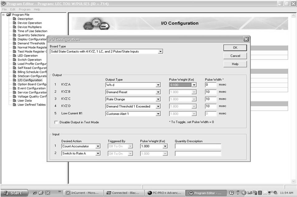
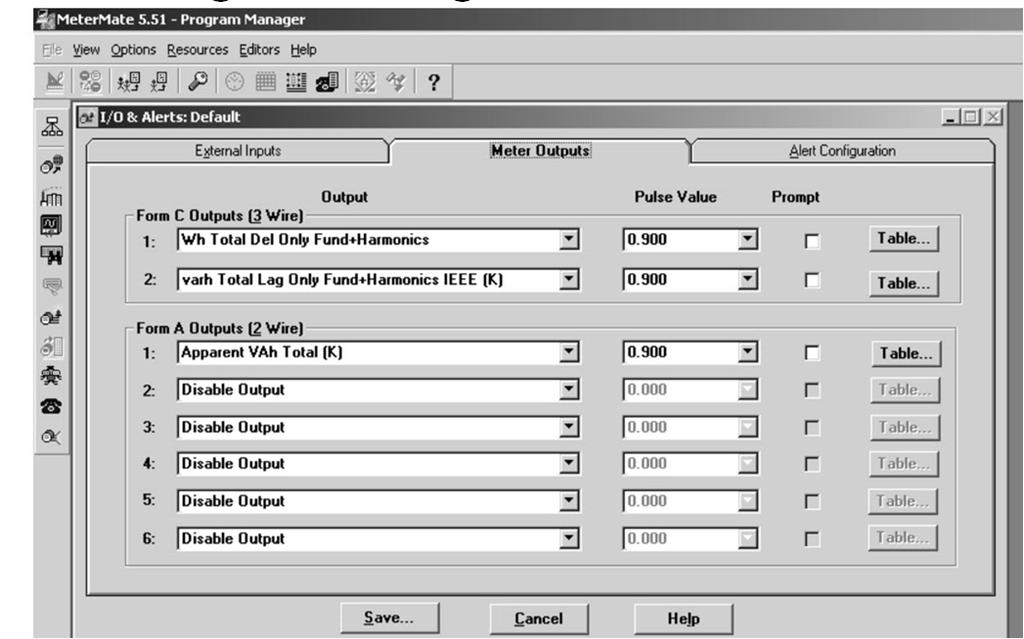
12 Pulse Programming Pulse Programming 12


13 Pulse Programming What is a Kh Value? Kh on an induction meter is the amount of energy measured during one disk revolution. Also called: Disk Constant Watthour Constant Meter Constant Expressed in Watt hours, not kilowatt hours per revolution of the eddy current disk 13

14 What is Kp? Kp is the pulse constant of an induction meter Same as Pke but on an electro mechanical induction meter Not programmable but determined by: Kh Meter Constant CTR Current Transformer Ratio PTR Potential Transformer Ratio Number of transitions per disk revolution: Pulses/Revolution (P/R) or Revolutions/Pulse (R/P) What is the Kp Pulse Constant? Also called PW or PC For calculating the Pulse Constant (Kp): For Pulses/Revolution: Kp = Kh X(CT x PT) P/R For Revolutions/Pulse: Kp = Kh X (CT x PT) XR/P 14
15 What is the Kp Pulse Constant? Example: Kh = 1.8 wh/rev CTR = 600/5=120 PTR = 1 P/R = 4 Kp = 1.8 (120X1) 4 =.054kwh/pulse or 54wh/p Maximizing Resolution Greatest resolution = demand divided by the maximum number of pulses in an interval. Example: Assume 1,000 kw load, 16,383 pulses/interval max, 15 minute demand interval Max Kwh/interval = 1000kW/4 = 250kwh (Kwh/interval)/(# pulses/interval) = 250kwh/16,383 Kwh/pulse (Pke) =.0153kwh/pulse So in this example: Pke = 16wh/pulse 15
16 Accounting for Growth Need to add a fudge factor so the max number of pulses per interval is not exceeded by load growth. (25% headroom) Peak KW = 1000KW/.75 = 1333KW Min Kd = 1333KW/16383 =.0813KW/pulse Min Kd =.082KW or 82 watts/pulse Min Pke =.082 / 4 =.0205 Kwh/pulse (~21wh/pulse) To keep from over ranging interval register, Ke must be greater than the Min Pke/TR or in this case: Ke =>.0205 / 160 = kwh The greater the Ke value, the fewer pulses per interval and the higher the demand can be measured in the interval, but resolution is lower. Insure that the maximum # pulses per interval will not overflow ( saturate ) the interval register. Important: Always round up not down Pulse Rate vs. Pulse Capacity Pulse Rate = the maximum number of pulses per second at which the pulse sending device is nominally rated. Pulse Capacity = the maximum number of pulses that the pulse receiving device can accept in a given period of time (usually a second, an hour or a demand interval). 16
17 Typical Max Pulse Capacity & Rates For old printing demand recorders: Capacity = 999 pulses/interval Max pulse rate = 1.11 pulses/second For old magnetic tape recorders: Capacity = 7200 pulses/hour Max pulse rate around 2 pulses/second For older solid state meters: Capacity = 16,383 pulses/interval (14 bit#) Max Pulse rate around 15 ~ 20 pulses/second Today s solid state meters Capacity = 65,535 pulses/interval (16 bit#) Max Pulse rate around 40 pulses/second Special Notes Pulse constants are usually expressed in 3 wire (Form C) format. Pulse values in 2 wire format are double the pulse value in 3 wire formats. Meter testing with Form C pulse outputs: Connect to either the KY or KZ terminals and then input to the test board. This configuration will only provide ½ the number of pulses for the programmed Ke pulse constant. Ke value must be doubled for a 2 Wire Pulse System 17
18 Pulse Initiators Simply stated a pulse initiator is a switch A device attached to an induction or solid state meter that transmits contact closures as the meter measures energy. Often called a KYZ Switch or KYZ Option Board. Each contact closure or opening (change of state) equals a defined value of energy, generally in kilowatt hours/pulse. Typically used to transmit energy consumption information on a near instantaneous basis to other pieces of equipment which use pulses. Pulse Initiators (aka KYZ switch) Mechanical pulse initiators used with induction meters Single output have a fixed pulse value determined by a watt hour constant (Kh) and gear ratio between the disk and the device. Today s solid state meters allow Multi channel, multi function output boards both the function and operational value of output relays to be programmable. Example: Let relay #1 represent kwh and each pulse = 192 wh Let relay #2 represent TOU time interval signal 18
19 Pulse Types KYZ Energy Pulses (Form C or Form A) EOI End Of Interval (Form A) TOU Time Of Use Signaling (Form A) Alert Peak demand alert Pulse Initiator Form C Simple Switch Model 19

20 Pulse Initiator Form C Simple Switch Model Pulse Initiator Board 20
21 Contact Types Dry Contacts have no electricity applied to them from the device in which they are installed. External voltage is supplied. Electrically Isolated Sourced Voltage Contacts generally have line voltage sourced to Y and Z terminals. Less Frequently Used Used only in special applications where non standard interface is required. Not isolated How Do Dry Contacts Work? Wetting Voltage sense voltage is applied from an external source on the K terminal. It can be detected on the Y and Z terminals alternately as the contacts open close. Utility Industry convention generally dictates that the receiving device supplies the wetting voltage to the sending device (relay to meter, energy control system to relay). This is not necessarily true with the Process Control Industry or Energy Management Industry. 21
22 Contact Forms Form A Normally open 2 wire contact; SPST Form C A set of contacts consisting of one form A and one form B with a single common contact ( K ); SPDT. One contact breaks before the other makes. Break Before Make Contact Forms Form A 2 wire, SPST, Normally Open 22
23 Contact Forms Form C 3 wire, SPDT Break before Make Each change of state is a pulse Recommended for applications where no overlapping of contacts can be tolerated 2-Wire vs. 3-Wire Systems 2 wire systems (Form A) historically lacked immunity to induced noise because there is a period of zero voltage between pulses when noise may occur, causing false triggering of pulses. 3 wire systems (Form C) are much less prone to noise because a signal (a voltage) is always present. Always one energized, never both 23
24 2-Wire vs. 3-Wire Systems 3 wire systems have Form C contacts 2-Wire vs. 3-Wire Systems Most 2 wire systems have normally open contacts (Form A) only Normally closed (Form B) are rare 24

 The Normally Open contact returns to")
25 Contact Output Devices Mercury Wetted Electromechanical Relay Solid State Low Power Opto MOS SSR Solid State High Power Opto MOS SSR Relay Terms to Know Latching Relay A relay that will stay in the last position it is in when voltage is removed; also called a Bi Stable Relay two stable states Non Latching Relay A relay with one stable state; also called Monostable. The Normally Closed contact returns to the closed state in absence of power; (Current can flow) The Normally Open contact returns to the open state.(no current flow) 25
26 More Relay Terms Polarized Relay Uses +Vdc and Vdc alternately to simulate 3 Wire system using only two wires. Generally requires a specific purpose transmitting and receiving relay for use in sending pulses over relatively long distances. Used a polarity reversing scheme to latch and unlatch a latching relay Info Needed for Pulse Metering Applications Type of meter, including Ke or Kh, voltage & current ratings CT & PT ratings and ratios Typical and Maximum kw demand Interval length usually 15 minutes Required contact types A or C Desired Pulse Rate or Resolution Programming limitations: Maximum number of pulses per interval Pulse capacity or the maximum pulse acceptance rate of the receiving equipment: Maximum number of pulses per second 26
27 Isolation Relays Isolation relays are pulse repeating relays that provide an additional level of electrical protection between the device that originates a contact closure (such as utility owned meters with KYZ pulse output) and the receiving device (such as a customer owned energy management or monitoring equipment). They can additionally act as a pulse splitter or pulse duplicator to send one KYZ pulse output from the pulse initiator in the meter to multiple isolated & independent devices, such as RTU s, scada systems, recorders, EMS etc. Isolation Relay Types Isolation Relays are divided into two basic types: Line Wetting Voltage These were the original isolation relays that used line voltage across the KYZ metering output to drive the input of the isolation relay. Not recommended. Low Voltage Wetting Voltage These have a small transformer isolated DC power supply included in the relay to generate a +12 to +24VDC wetting voltage and is current limited for internal short circuit protection. Using a transformer isolated power supply adds a second dielectric or isolation barrier to the application. 27


28 Why do we use these devices? 1. Protection: prevent possible damage to meter To keep the customer s voltage and current out of the meter Protect meter from Lightning; Protect customer equipment Adds a second dielectric barrier between the utility meter and the customer s equipment. Adds Fusing to the customer output circuit 2. Separate Line and ground potentials 3. Mitigate Ground rise problems between systems 4. Pulse Voltage conversion 5. Scale pulse value from one value to required value to reduce # of pulses Pulse Isolation Relay Application Meter with EPI Isolation Relay KYZ KYZ KYZ SCADA component Recorder or EMS 28


29 Pulse Isolation Relay Application Pulse Isolation Relay Circuit 29

30 Output Relay Types Low Power Silicon (Solid State) Relays lower current carrying capability (100mA), higher on state resistance, lower cost, more prone to lightning damage & noise; non latching, optically coupled, 2500V High Power Silicon (Solid State) Relays lower current carrying capability (750mA), lower on state resistance, higher cost, less prone to lightning damage & noise; non latching, optically coupled, 2500V. Mercury Wetted Relays have a reed relay encapsulated in a glass tube with a small amount of mercury around the contact point to prevent arcing or bounce when the contacts close; 2A current carrying capability, highly impervious to lightning damage; usually latching, 1500V. Special Notes MW isolation relays must be installed in a vertical position (within 30 degrees of vertical). Some isolation relays may have fuses for each output relay AND a slow blow input fuse (~.25.5 amp). Some relays offer redundant fusing so customer cannot defeat fuse with a large amperage fuse. 30
31 Selecting the Proper Isolation Relay Self contained (outdoor) or modular (indoor)? Input format (2 wire, 3 wire or field selectable)? Output format (2 wire, 3 wire, dividing type, or fieldselectable)? Sense Voltage (Line voltage or isolated low voltage wetting voltage)? Can the sending device accept non isolated line voltages? Cont.. Selecting the Proper Isolation Relay What is the minimum time the sending device s contact is made up (>25 ms)? (40pps) What is the minimum current the sending device can switch (>10 ma) to reliably operate the relay? What is the maximum output current the relay can switch (>100mA to <2 amps)? How many isolated dry contact outputs are required? (1,2,3,4 or 6) Highest Input to Output Isolation voltage you can get: 2500V vs. 3750V 31
32 Typical Specifications Inputs Pulse Inputs: 1 4; Type: Form A,C Power Supply Voltage: 120V 277V Power (Burden) ~2 w Max Pulse Rate accepted (transitions/second) Surge Suppression(VAC) Internally generated +13VDC wetting voltage Outputs Number (1 6) Type (Dry contact, Mercury Wetted or Solid State, Form A,C) Maximum Contact Voltage & Current Contact VA Rating Contact Life (# operations at maximum ratings) Surge Suppression (VAC) Current Limiting or Fusing Typical Specifications Contact On State Resistance 50 milliohms max for MW 20 ohms typical for LP SSR 1.7 ohms typical for HP SSR Insulation Resistance (50 megohms typical) Operate and Release Time (Typically 1 to 10 milliseconds) Maximum Dielectric Voltage 1500V for MW V for SSR 32
 Unit Isolation Relay Selection Typical")

33 Isolation Relay Selection Typical Self-Contained (Outdoor) Unit Isolation Relay Selection Typical Modular Relays Form C (3 wire in 3 wire out) Low Voltage Select number or low voltage outputs desired 33

34 Isolation Relay Selection Totalizers / Pulse Accumulators Multiple Inputs One or more outputs Programmable input & output values 5 Take-Aways 1. A pulse is a switch closure SPDT 2. Each switch closure is a representation of a fixed amount of energy which has gone past the meter 3. Dry contacts must be wetted with a voltage generally from the pulse receiving ( downstream ) device 4. 2 wire values are double 3 wire values 5. Isolation Relays can protect your meter and your customer s equipment: Think separation of circuits. 34


35 Questions & Answers For Copy of Presentation, please send to or give me your business card 35
INSTALLATION INSTRUCTION SHEET MPG-1 Metering Pulse Generator
 Output Status LEDs Dip Switch Communication Status LEDs INSTALLATION INSTRUCTION SHEET MPG-1 Metering Pulse Generator Y Z S1 OUTPUT 1 PULSE VALUE OUTPUT MODE OUTPUT PULSE WIDTH (ms) 2 3 4 5 6 Outputs Z1
INSTALLATION INSTRUCTION SHEET MPG-1C Metering Pulse Generator
 INSTALLATION INSTRUCTION SHEET MPG-1C Metering Pulse Generator V2.12 Firmware Output Status LEDs Zigbee Communication Status LEDs Y Z Outputs Z1 K2 Y2 Z2 K1 Y1 Z2 Y2 K2 Z1 Y1 K1 OUTPUT #2 OUTPUT #1 USB
ELKOR MOC1 TRANSDUCER SET - MANUAL
 ELKOR MOC1 TRANSDUCER SET - MANUAL Elkor MOC1 Power Transducer - Product Description The MOC1 true RMS 3 phase transducer is a micro-processor based metering product that provides a cost effective and
Technical Data Sheet
 Technical Data Sheet parameters in 3 phase 4 Wire and 3 phase 3 Wire Network & replaces the multiple analog panel meters. Special Features Pulse/Limit Switch output (optional) Number of interruption Application
Product Manual SE1000. Description The SE1000 is a microprocessor-based pulse monitoring interface designed to monitor up to four pulse inputs.
 Product Manual SE1 Utility Meter Pulse Transducer Communicating Controls Description The SE1 is a microprocessor-based pulse monitoring interface designed to monitor up to four pulse inputs. Features Stand-alone
INSTRUCTION SHEET MPT-440 ISOLATION RELAY/TOTALIZER
 INPUT #1 INPUT #2 INPUT #3 INPUT #4 POWER SUPPLY INPUT INSTRUCTION SHEET MPT-440 ISOLATION RELAY/TOTALIZER EOI INPUT Ground Neutral 120VAC 208-277 VAC 1in Y1in Z1in 2in Y2in Z2in 3in Y3in Z3in 4in Y4in
RISH Master Digital Multifunction Instrument with onsite pluggable output options. Application : Product Features:
 Application : RISH Master 3430 measures important electrical parameters in 3 phase and single phase Network & replaces the multiple analog panel meters. It measures electrical parameters like AC current,
MICROPROCESSOR-BASED METERING EQUIPMENT SECTION 16901C PART 2
 PART 1 PART 2 PRODUCTS 2.01 MANUFACTURERS A. Eaton products B.. C.. The listing of specific manufacturers above does not imply acceptance of their products that do not meet the specified ratings, features
354B SERIES SHAWNEE II High Speed Predetermining
 354B SERIES SHAWNEE II High Speed Predetermining DIMENSIONS INCHES MILLIMETERS The 354B Directly Replaces 354A. A compact version of the 334 counter, the ATC 354B is its exact functional duplicate. Packaged
INTELLIMETER REGISTER
 INTELLIMETER REGISTER OPERATING INSTRUCTIONS WARNING: Any work on or near energized metering equipment can present a danger of electrical shock. All work on these products should be performed only by qualified
Data Sheet. RISH Master Record %THD
 Data Sheet %THD Application : measures important electrical parameters & replaces the multiple analog panel meters. It measures electrical parameters like AC current, Voltage, frequency, active energy
RISH EM 3490 SS Kilowatt Hour Energy Meter With Rs485 RISH EM 3490 SS. Application : Product Features: Indication: Pulse Indication:
 Application : RISH Master 3490 SS is a 96mm x 96mm panel mounted kilowatt hour meter it measures active energy with class 1.0 accuracy having auto-resetting 8 digit seven segment LED counter. The unit
ALPHA 20 MULTIFUNCTION METER (ALPHA SERIES)
") Alpha Series www.sifamtinsley.co.uk Multifunction Meters Transducers & Isolators Temperature Controllers Converters & Recorders Digital Panel Meters Current Transformers Analogue Panel Meters Shunts ALPHA
Alpha Series www.sifamtinsley.co.uk Multifunction Meters Transducers & Isolators Temperature Controllers Converters & Recorders Digital Panel Meters Current Transformers Analogue Panel Meters Shunts ALPHA
Series 354. SHAWNEE II High-Speed Digital Predetermining Counter. The 354B Directly Replaces 354A. COUNTERS PRODUCT HIGHLIGHTS
 Series 354 SHAWNEE II High-Speed Digital Predetermining Counter The 354B Directly Replaces 354A. A compact version of the 334 counter, the ATC 354 is its exact functional duplicate. Packaged in a 72mm
Digital Multifunction Instrument - Rish Master 3440
 Application Rish Master 3440 measures important electrical parameters in 3 phase and single phase etwork & replaces the multiple analog panel meters. It measures electrical parameters like AC current,
Primary Metering. What is Primary Metering?
 NWEMS Primary Metering August 22, 2018 Bill Unbehaun, Tacoma Power Exchanging Expertise Since 1893 What is Primary Metering? Metering energy flow past a point at high voltage above 600v Both PTs and CTs
Technical Information General Purpose Relays
 Glossary CONTACTS Contact Form The contact mechanism of the Relay. Number of Contact Poles The number of contact circuits. Rated Load The rated load of the contact of the Relay, which determines the characteristic
ALPHA 50 MULTIFUNCTION METER (ALPHA SERIES)
") Alpha Series www.sifamtinsley.co.uk Multifunction Meters Transducers & Isolators Temperature Controllers Converters & Recorders Digital Panel Meters Current Transformers Analogue Panel Meters Shunts ALPHA
Alpha Series www.sifamtinsley.co.uk Multifunction Meters Transducers & Isolators Temperature Controllers Converters & Recorders Digital Panel Meters Current Transformers Analogue Panel Meters Shunts ALPHA
Model: 3283N 3283N. Demand Control Module (Interface with Utility Pulse Meter) FEATURES: APPLICATIONS:
 FEATURES: APPLICATIONS:") 3283N 3283N Demand Control Module is an interface between the Utility Companies' Demand meter and the Controller. Solidyne designed the 3283N to provide a stable contact input to the Controller from the
3283N 3283N Demand Control Module is an interface between the Utility Companies' Demand meter and the Controller. Solidyne designed the 3283N to provide a stable contact input to the Controller from the
RISH Master 3430 DIGITAL MULTI-FUNCTION TRANSDUCER. Electro-Meters
 measures important electrical parameters in phase and single phase etwork & replaces the multiple analog panel meters. It measures electrical parameters like AC current, Voltage, frequency, Power, Energy
Application Alpha 20 Measures important electrical parameters in 3 phase 4 Wire and 3 phase 3 Wire Network & replaces the multiple analog panel meters
 Technical Data Sheet Alpha 20 Alpha 20 is a compact multifunction instrument which Measures important electrical parameters in 3 phase 4 Wire and 3 phase 3 Wire Network & replaces the multiple analog panel
RISH EM 3490 DS Dual Source Energy Meter (With All Display Parameters) RISH EM 3490 DS. Application : Product Features:
 RISH EM 3490 DS. Application : Product Features:") (With All Display Parameters) Application : RISH EM 3490 DS measures important electrical parameters of Utility (in normal mode) & Generators (in Power back up) in three phase and single phase Network
(With All Display Parameters) Application : RISH EM 3490 DS measures important electrical parameters of Utility (in normal mode) & Generators (in Power back up) in three phase and single phase Network
NWEMS. Totalization. Aug 22 nd, 2017 NW Meter School Track D Will Elliott, Aclara Technologies EXCHANGING EXPERTISE SINCE 1893
 NWEMS Totalization Aug 22 nd, 2017 NW Meter School Track D Will Elliott, Aclara Technologies Page 1 Why Totalize? Multiple feeders into a facility Combines energy summations per interval Combines demand
Integra 1560 and 1580 Digital Transducer Systems
 Integra 1560 and 1580 multi function transducers provide high accuracy
Electromechanical Printed Circuit Board Relays Application Data
 Electromechanical Printed Circuit Board Relays Application Data Introduction: In the past several years the dry reed relay has become an important product among relay specifiers, primarily because of the
Protection Basics Presented by John S. Levine, P.E. Levine Lectronics and Lectric, Inc GE Consumer & Industrial Multilin
 Protection Basics Presented by John S. Levine, P.E. Levine Lectronics and Lectric, Inc. 770 565-1556 John@L-3.com 1 Protection Fundamentals By John Levine 2 Introductions Tools Outline Enervista Launchpad
Technical Data Sheet. x1000. kwh R Y B
 Technical Data Sheet x1000 Von kwh IRev 3600 imp /kwh R Y B is a compact multifunction instrument which is a 96mm x 96mm panel mounted kilowatt hour meter it measures active energy with class 1.0 accuracy
white paper A primer A utomated Signal Switching reliable data first time every time
 white paper A utomated Signal Switching 1 Overview Routing electrical and even optical signals from one source to another requires an overall understanding of the application, signals being switched and
PCB Relay SPST-NO G6CU-1117P-US G6CU-1114P-US G6CU-1117C-US G6CU-1114C-US SPST-NO + SPST- G6CU-2117P-US G6CU-2114P-US G6CU-2117C-US G6CU-2114C-US
 PCB Relay SPST-NO Type Breaks 10-A Loads; SPST-NO + SPST-NC Type Breaks 8-A Load Compact: 20 15 10 mm (L W H). Low power consumption: 200 mw. Flux protection or fully sealed construction available. Unique
UNIVERSAL MEASURING INSTRUMENTS. TNM 34xx. TNM 3410 / 3420 / 3430 / 3440 Universal measuring instrument 1/49
 TNM 3410 / 3420 / 3430 / 3440 Universal measuring instrument True RMS measurement User-friendly programing Four different types for optimal specification RS485 interface For 3- or 4-wire connection Compact
PCB Relay. Ordering Information. SPST-NO Type Breaks 10-A Loads; SPST-NO + SPST-NC Type Breaks 8-A Load
 PCB Relay SPST-NO Type Breaks 10-A Loads; SPST-NO + SPST-NC Type Breaks -A Load Compact: 20 x 15 x 10 mm (L x W x H). Low power consumption: 200 mw. Flux protection or plastic-sealed construction available.
NEW DIGITAL PUMP LOAD CONTROL
 NEW DIGITAL PUMP LOAD CONTROL Power sensor monitors true motor power Waterproof & rugged, large red LED display Compact enclosure with flexible fittings Easy front panel keypad set up Low and high setpoint
AMIK 200 / 201 Technical Data Sheet
 AMIK 200 / 201 Technical Data Sheet AMIK Special Features MODBUS (RS-485) Communication available only on Amik 201 On site Programmable CT/PT Ratios User selectable CT Secondary 1A/5A User selectable PT
Back to the Basics Current Transformer (CT) Testing
 Testing") Back to the Basics Current Transformer (CT) Testing As test equipment becomes more sophisticated with better features and accuracy, we risk turning our field personnel into test set operators instead of
Back to the Basics Current Transformer (CT) Testing As test equipment becomes more sophisticated with better features and accuracy, we risk turning our field personnel into test set operators instead of
Technical Data Sheet AMIK 300 / 301
 USA SINCE 1936 RELIABILITY BEYOND MEASURE Technical Data Sheet AMIK 300 / 301 LISTED File No. E471457 AMIK AMIK 300 is a compact multifunction instrument with touch screen LCD utility which measures important
Advanced, accurate and intelligent monitoring for your transformer
 QUALITROL 505 ITM Intelligent transformer monitor Advanced, accurate and intelligent monitoring for your transformer The power to know your transformer health immediately with TransLife Advanced thermal
Improve asset protection and utilization
 QUALITROL 509 ITM Intelligent transformer monitor Improve asset protection and utilization Immediately know your transformer health with TransLife Optimize loading and equipment life Simplify root cause
ENGLISH 3 Phase Multi-function Power Meter 1/5A MID MID
 Professionally approved products. Datasheet Stock Number: 144-0527 3 Phase Multi-function Power Meter 1/5A MID 96mm² Panel Mounted Power Meter. MID UK Specifications The 144-0527 is a new generation modern
Application: Product Features: On site programmable PT/CT ratios: User selectable CT Secondary 5A/1A. User selectable PT Secondary
 Application: Rish Master 3440 measures important electrical parameters in 3 phase and single phase etwor & replaces the multiple analog panel meters. t measures electrical parameters lie AC current,, frequency,
Ordering Information. Latching Relay MMK. Available Models. Models Conforming to Auxiliary Power Relay Specifications
 Latching Relay MMK CSM_MMK_DS_E_1_1 Mechanically Latching Relays Based on the MM Power Relay Low power consumption due to mechanical latch for economic operation. Relays with mixed coil specifications
SULTANATE OF OMAN METERING AND DATA EXCHANGE CODE
 1.0 GENERAL SULTANATE OF OMAN METERING AND DATA EXCHANGE CODE STANDARD: OES-22F THREE PHASE KILOWATT-HOUR DIGITAL METERS, CURRENT TRANSFORMER OPERATED, CONNECTED FOR SERVICE CONNECTIONS Electronic three
Arbiter Systems, Inc Vendels Circle, Suite 121 Paso Robles, CA USA
 Model 931A Power System Analyzer Model 930A Three Phase Power Analyzer Model 929A Three Phase Power Meter with Digital Signal Analysis Model 931A shown with included accessories Arbiter Systems, Inc. Models
POWER MONITORING For Energy Management Systems
 POWER MONITORING For Energy Management Systems Technologies Inc. 2004 This guide covers only a small portion of the rather extensive field of electrical metering. If you have any questions regarding this
9320 Series. Demand Monitors. Installation & User s Manual. a product of
 9320 Series Demand Monitors Installation & User s Manual a product of 9320 SERIES INSTALLATION AND USER S MANUAL P/N 09320-94100B REV. 5/1/2006 1995-2006 Brayden Automation Corporation Brayden Automation
WATT TRANSDUCER. Instruction Manual
 WT 9200 WATT TRANSDUCER Instruction Manual IM-2 September 2003 USA: 6428 Ridglea Drive, Watauga, Texas 76148 Tel/Fax 1-817-427-2060/2067 E-mail: wes@westecinstruments.com SPECIFICATIONS Power Supply Input
WIRELESS INSULATOR POLLUTION MONITORING SYSTEM
 SYSTEM OVERVIEW Pollution monitoring of high voltage insulators in electrical power transmission and distribution systems, switchyards and substations is essential in order to minimise the risk of power
Issue Date: Effective Date: Supersedes: S-E-06 (rev. 6)
") Specifications Category: ELECTRICITY Specification: S-E-06 (rev. 7) Page: 1 of 22 Issue Date: 2017-02-01 Effective Date: 2017-02-01 Specification for the approval of type of electricity meters and auxiliary
Specifications Category: ELECTRICITY Specification: S-E-06 (rev. 7) Page: 1 of 22 Issue Date: 2017-02-01 Effective Date: 2017-02-01 Specification for the approval of type of electricity meters and auxiliary
DST-2000C. Direction Sensing Tachometer INSTRUCTION MANUAL
 DST-2000C Direction Sensing Tachometer INSTRUCTION MANUAL Azonix-Dynalco, 3690 N. W. 53 Street, Ft. Lauderdale, FL 33309 U.S.A.! (954) 739-4300 Fax (954) 484-3376 www.dynalco.com mailbox@dynalco.com October
Power PCB Relay. To Order: Select the part number and add the desired coil voltage rating (e.g., G6B-1114-US-DC6).
.") Power PCB Relay Subminiature 20 L x 9.90 W x 9.90 H mm (0.79 L x 0.39 W x 0.39 H in) Low power consumption (200 mw) Sealed construction permits automatic soldering and cleaning of the PC board High-capacity
Power PCB Relay Subminiature 20 L x 9.90 W x 9.90 H mm (0.79 L x 0.39 W x 0.39 H in) Low power consumption (200 mw) Sealed construction permits automatic soldering and cleaning of the PC board High-capacity
Low profile safety relay with forcibly guided double contacts FEATURES. Relay height, 14.5mm. 4a2b
 Low profile safety relay with forcibly guided double contacts SFN4D RELAY 3.3 33.0 FEATURES Relay complies with EN 020, Type B. Polarized magnet system with snap action function Tolerance ±0.3 mm Weight
Anacon Power & Controls
 2254 Main Street, Concord, MA 01742-3829 Tel: 800-466-9080 978-287-0715 Fax: 978-287-0952 www.anaconpower.com sales@anaconusa.com SCR Power Controllers Zero Cross Time Based / Burst Fire C - SCR (Burst)
Practical Tricks with Transformers. Larry Weinstein K0NA
 Practical Tricks with Transformers Larry Weinstein K0NA Practical Tricks with Transformers Quick review of inductance and magnetics Switching inductive loads How many voltages can we get out of a $10 Home
Metering Devices, Protective Relays, Software and Connectivity
 , Protective Relays, Software and Connectivity.3 IQ Analyzer 6400/6600 Series IQ Analyzer Comprehensive Electrical Distribution Monitoring IQ Analyzer 6400/6600 Series Product Description Eaton s IQ Analyzer
Introduction to Solid State Meter Testing. Terms and Definitions
 NWEMS Introduction to Solid State Meter Testing 2017 Northwest Electric Meter School Presented by: Marcus Zickefoose Radian Research Inc. Terms and Definitions Term Definition Accuracy Calibration Class
Installation, Operation and Maintenance Manual
 M518 Rev. B Model 1030F Indicator-Totalizer Model 1030F Indicator-Totalizer Installation, Operation and Maintenance Manual Table of Contents General... 1 Installation... 1 Operation... 7 Programming...
UL CONDITIONS OF ACCEPTABILITY
 Certificate Number: 1018011-1 Date: 2016-10-06 UL CONDITIONS OF ACCEPTABILITY Company Name: FUTURE DESIGN CONTROLS INC File-CCN: E197216 - QUYX2 Product Description: Process Control Equipment, Electrical
Anacon Power & Controls Relay Assembly Specialists An Anacon Electronic Sales, Inc. Company
 ZERO CROSS SSR CONTROLLER USERS MANUAL SSR INTELLIGENT POWER CONTROL MODULE TABLE OF CONTENTS Section Page 1 Ordering Code... 3 2 Description... 3 2.1 Features... 3 3 Installation... 3 3.1 Mounting Instructions...
Ratchet Relay. Ordering Information. Unique Ratchet Mechanism Assures Positive Alternate Transfer/Switching Operation. G4Q-jjjj
 Ratchet Relay Unique Ratchet Mechanism Assures Positive Alternate Transfer/Switching Operation Each contact in the double-pole contact mechanism performs alternate make-brake operation at each pulse input
BATCHMATE 1500 Batch Control Computer Technical Bulletin
 TS-5(C) BATCHMATE 5 Batch Control Computer Technical Bulletin DESCRIPTION The BATCHMATE features an 8 digit.55-in. alphanumeric LED display. The pulse input model will accept up to 2, pulses per second
G6C. Miniature High Capacity Relays with SPST-NO 10A and SPST-NO + SPST-NC 8A. Model Number Legend. Application Examples.
 Miniature High Capacity Relays with SPST-NO 0A and SPST-NO + SPST-NC A SPST-NO 0A and SPST-NO + SPST-NC A for power switching and output that satisfy the needs for space-saving. Small High-capacity Relays
Generator Advanced Concepts
 Generator Advanced Concepts Common Topics, The Practical Side Machine Output Voltage Equation Pitch Harmonics Circulating Currents when Paralleling Reactances and Time Constants Three Generator Curves
OHIO SEMITRONICS, INC. WATT / Wh / VAR / VARh TRANSDUCER OSI SPECIFICATIONS
 N OSI DESCRIPTION Model Wxx transducers utilize a microprocessor based design with high speed analog-to-digital converters to provide accurate measurement of real power, reactive power and energy delivered
INSTALLATION INSTRUCTIONS FOR SYMCOM S MODEL 77C-LR-KW/HP ELECTRONIC OVERLOAD RELAY
 INSTALLATION INSTRUCTIONS FOR SYMCOM S MODEL 77C-LR-KW/HP ELECTRONIC OVERLOAD RELAY BE SURE POWER IS DISCONNECTED PRIOR TO INSTALLATION! FOLLOW NATIONAL, STATE AND LOCAL CODES. READ THESE INSTRUCTIONS
ABB CUSTOMER WORLD, MARCH 13-16, 2017 Sensors in Critical Applications Ron Pate, Product Manager, Instrument Transformers and Sensors
 ABB CUSTOMER WORLD, MARCH 13-16, 2017 Sensors in Critical Applications 050511 Ron Pate, Product Manager, Instrument Transformers and Sensors Sensors in Critical Applications Presentation code 050511 Speakers
Device Under Test: ALTEA VS- 24-I VS-24-I. 0 24/09/12 First issue A. Peretto L. Peretto 1 24/06/16 All text review E. Scala L. Peretto J. L.
 /9 TECHNICAL SPECIFICATIONS VOLTAGE LOW-POWER TRANSFORMER VS- Rev. Date Revision Description Prepared by Checked by Approved by 0 24/09/2 First issue A. Peretto L. Peretto 24/06/6 All text review E. Scala
RISH PQM. Power Quality Monitor. Preliminary Datasheet subject to change without notice. Individual Harmonics measurement upto 56th Harmonics
 Power Quality Monitor Individual Harmonics measurement upto 56th Harmonics True representation of Voltage & Current waveforms. Phasor Representation of All 3 phases for system analysis Real Time Clock
Table of Contents. Kilovac Time Delay Relays
 Table of Contents 1600/1700 Series, Delay on Operate, Fixed & Adjustable......................8-2, 8-3 2400 Series, Subminiature, Delay on Operate, Fixed.............................8-4 5600/5700 Series,
POWER TRANSDUCERS ACTIVE AND REACTIVE SERIES: T-W WATT T-V VAR
 POWER TRANSDUCERS ACTIVE AND REACTIVE SERIES: T-W WATT T-V VAR The T-W or T-V power transducer converts ac current and voltage signals into a load independent dc signal proportional to active power (watts)
Over or Under Current. Over and Under Current Monitor. Current Transducer. Current Indicator. DIN Rail Mounting Current Monitors
 Selection Guide...8.2 Over or Under ECS... 8.4 TCS... 8.8 Over and Under Monitor ECSW... 8.6 Transducer TCSA... 8.10 DCSA... 8.12 Indicator LCS... 8.14 LPM... 8.14 DIN Rail Mounting CM-SFS CM-SRS.1 CM-SRS.2
EASTRON SDM630MCT-RJV / SDM630MCT-RJA User Manual V1.1. Three phase multifunction din rail energy meter
 SDM630MCT-RJV-333mV SDM630MCT-RJA-00mA Three phase multifunction din rail energy meter Plug-in solution; labor saving; wiring mistake free Measures kwh KVarh, KW, Kvar, KVA, P, F, PF, Hz, dmd, V, A, THD,etc.
RISH Delta Energy / Demand (Multifunction instrument) Data Sheet
 Data Sheet") ISH Delta Energy / Demand (Multifunction instrument) Data Sheet www.rishabh.co.in Page 1 of 6 Version: D 14 / 03 / 2012 Application: ISH Delta Energy measures important electrical parameters in 3 phase
ISH Delta Energy / Demand (Multifunction instrument) Data Sheet www.rishabh.co.in Page 1 of 6 Version: D 14 / 03 / 2012 Application: ISH Delta Energy measures important electrical parameters in 3 phase
Energy Meters for DIN Rail Mounting Electric energy meter WS0101, WS0102,WS1102 WS0301, WS0302,WS1302
 Energy Meters for DIN Rail Mounting Electric energy meter WS0101, WS0102,WS1102 WS0301, WS0302,WS1302 Direct connection up to 65 A (WSx10x) Connection with current transformer (WSx30x) Industrial or meters
Panel Mount Tachometer, PE5
 Features Plug-n-play units with factory programmed parameters 4-20 ma feedback signal Isolated relay alarm outputs Frequency input Operating voltages: 120 VAC, 240 VAC Diagnostic indicators Model PE5,
AN-B21C-0004 Applications Note
 Rev. A, 10/12/09 SD 2009 Coto Technology All Rights Reserved 1/10 B21C Relay Specification Data TEST PARAMETERS CONDITIONS 1,2 MIN NOM MAX UNITS COIL SPECIFICATIONS COIL RESISTANCE 140.0 155.0 170.0 Ω
PM 305 Operating Guide
 PM 305 Operating Guide Northern Design PREFACE PM305 Operating Guide Revision 2.05 October 2000 This manual represents your meter as manufactured at the time of publication. It assumes standard software.
SECTION 3 BASIC AUTOMATIC CONTROLS UNIT 12 BASIC ELECTRICITY AND MAGNETISM. Unit Objectives. Unit Objectives 2/29/2012
 SECTION 3 BASIC AUTOMATIC CONTROLS UNIT 12 BASIC ELECTRICITY AND MAGNETISM Unit Objectives Describe the structure of an atom. Identify atoms with a positive charge and atoms with a negative charge. Explain
UNIT II MEASUREMENT OF POWER & ENERGY
 UNIT II MEASUREMENT OF POWER & ENERGY Dynamometer type wattmeter works on a very simple principle which is stated as "when any current carrying conductor is placed inside a magnetic field, it experiences
PQube 3 Specifications
 PQube 3 Specifications Reference conditions for factory tests: 19~25 C, 10%~70% RH MAINS VOLTAGE MEASURING CHANNELS Measurement Channels Power Configuration/ Range of Nominal Input Voltage 3 Line to Neutral,
ULTRA RAPID POWER QUALITY ANALYZER
 ULTRA RAPID POWER QUALITY ANALYZER Ultra rapid (cycle by cycle) advanced electrical network analysis Complete network harmonics analysis, up to 63 rd harmonic High visibility, 5 graphic LCD screen with
RI-F200 Series. Single and Three Phase Multifunction Energy Meter. Telephone : +44 (0) Displayed Parameters
 Displayed Parameters") RI-F200 Series Single and Three Phase Multifunction Energy Meter DIN 96 panel mounted -/1A or -/5A current transformer input Single phase or three phase network compatible Programmable voltage and current
RI-F200 Series Single and Three Phase Multifunction Energy Meter DIN 96 panel mounted -/1A or -/5A current transformer input Single phase or three phase network compatible Programmable voltage and current
Surface-mounting Relay
 Surface-mounting Relay Extremely Thin SPST-NO Flat Relay, One of the Thinnest Relays in the World Dimensions of 7.(W).6(L) 4.2 mm(h) (SMD) or 3.8 mm(h) (TH) represent a reduction of approximately 2% in
DIN Rail Kilowatt Hour Energy Meters
 DIN Rail Kilowatt Hour Energy Meters Single Phase DIN Rail Kilowatt Hour Energy Meters DRK-1PPO-240 Single Phase 230V - 15A Direct Connected, Pulse Output This innovative two DIN module kilowatt hour energy
Alpha 50. Technical Data Sheet. Special Features
 Technical ata Sheet lpha 50 lpha 50 is a compact multifunction instrument with touch screen LC utility which measures important electrical parameters in 3 phase and single phase Network & replaces the
PREMIER INSTALLATION AND OPERATING INSTRUCTIONS
 PREMIER INSTALLATION AND OPERATING INSTRUCTIONS Copyright 2002-2006, PRI Ltd. 9600-3003-2 Issue C Information contained within this document is subject to change without notice and does not represent a
USER MANUAL MODEL USFT-B ULTRASONIC FLOW TRANSMITTER. Rev USER MANUAL DEI MODEL USFT-B
 Rev012008 USER MANUAL DEI MODEL USFT-B USER MANUAL MODEL USFT-B ULTRASONIC FLOW TRANSMITTER The Model USFT-B is an ultrasonic transit time flow meter designed to accurately and reliably report the flow
TRANSFORMER CONTROL (AC-56a)
") Solid State Relays (SSR) TRANSFORMER CONTROL (AC-56a) celduc relais solutions Tips and tricks to make good control of transformer primary using celduc relais solutions TECHNICAL INFORMATION Switching ON
Solid State Relays (SSR) TRANSFORMER CONTROL (AC-56a) celduc relais solutions Tips and tricks to make good control of transformer primary using celduc relais solutions TECHNICAL INFORMATION Switching ON
AC/DC to Logic Interface Optocouplers Technical Data
 H AC/DC to Logic Interface Optocouplers Technical Data HCPL-37 HCPL-376 Features Standard (HCPL-37) and Low Input Current (HCPL-376) Versions AC or DC Input Programmable Sense Voltage Hysteresis Logic
INSTALLATION AND MAINTENANCE MANUAL FOR GROUND MONITOR GM-250 COPYRIGHT 1983 AMERICAN MINE RESEARCH, INC.
 INSTALLATION AND MAINTENANCE MANUAL FOR GROUND MONITOR GM-250 COPYRIGHT 1983 AMERICAN MINE RESEARCH, INC. MANUAL PART NUMBER 180-0036 ORIGINAL: 1-17-83 REVISION: B (8-26-86) NOT TO BE CHANGED WITHOUT MSHA
Section L5: PRE-ENERGIZATION TEST PROCEDURES FOR LOAD-ONLY ENTITIES AND TRANSMISSION-ONLY ENTITIES
 Section L5: PRE-ENERGIZATION TEST PROCEDURES FOR LOAD-ONLY ENTITIES AND TRANSMISSION-ONLY ENTITIES PURPOSE The following is PG&E's procedure for pre-energization inspections. For PG&E to provide the Load
Model 1133A Power Sentinel. with. Digital Signal Analysis SYNCHRONIZED POWER QUALITY/REVENUE STANDARDS
 Model 1133A Power Sentinel with Digital Signal Analysis Synchronized via GPS Revenue Accuracy: 0.025% Power Quality: Harmonics, Flicker, Interruptions Phasor Measurements for Stability & Flow Analysis
3. Contact Form A: SPST-NO
 0 A Compact and high power latching relay High power switching: 0 A, 6 VAC Compact size: mm mm mm Low temperature-rise High overcurrent capability, conforming to IEC6055- UC RoHS Compliant Model Number
KNOW MORE ABOUT THE TRANSFORMERS. Glossary Transformers
 KNOW MORE ABOUT THE TRANSFORMERS Glossary Transformers Ambient temperature The existing temperature of the atmosphere surrounding a transformer installation. Ampere The practical unit of electric current.
CPC1964B AC Power Switch
 AC Power Switch Parameter Rating Units AC Operating Voltage - 28 V rms Load Current 1. A rms On-State Voltage Drop 1.4 V P (at = 1.A P Blocking Voltage 8 V P Features Load Current up to 1.A rms 8V P Blocking
Classification Contact form Enclosure rating Terminal shapes Model Minimum packing unit Standard. SPST-NO (1a) Fully sealed PCB terminal
 Fully sealed PCB terminal") SPST Slim Power Relay for A switching Slim -mm width and miniature size. (20.08 12. mm) High switching capability A (20 VAC and VDC), and high contact reliability by crossbar-twin contact. Low power consumption
SPST Slim Power Relay for A switching Slim -mm width and miniature size. (20.08 12. mm) High switching capability A (20 VAC and VDC), and high contact reliability by crossbar-twin contact. Low power consumption
EM-100 Controller. Installation Precautions. July 2016
 EM-100 Controller Installation Precautions July 2016 Table of Contents 1 Overview... 3 2 The Issue... 3 3 Configuration Tutorial... 3 3.1 Working Principle... 3 3.2 Design... 5 3.3 Induction at the Opening
BEE 2233 Digital Electronics. Chapter 1: Introduction
 BEE 2233 Digital Electronics Chapter 1: Introduction Learning Outcomes Understand the basic concept of digital and analog quantities. Differentiate the digital and analog systems. Compare the advantages
DPDT+DPST-NO MM4KP-JD MM4XKP-JD
 Latching Relay CSM DS_E_6_1 Mechanically Latching Relays Based on the MM Power Relay Low power consumption due to mechanical latch for economic operation. Relays with mixed coil specifications can be produced
MINIATURE SIGNAL RELAYS
 Information MINIATURE SIGNAL RELAYS UA SERIES (DIP Type) UB SERIES (SMD Type) TECHNICAL DATA EM Devices Corporation 17 EMDST5VOL1E17H The information in this document is based on documents issued in March,
Proximity Sensor Terminology
 The following descriptions refer to the European standard EN 60947-5-2. of 2007. The specifications given here are intended to be minimum performance values described by the standard. Alignment must not
Jewell DPM Power / Power Factor Size 96/96 BEST IN CLASS
 Application: The Jewell DPM Power 96x96 series measures system active Power (Import/Export), Reactive Power (Import/Export), Apparent Power & Power Factor of Three Phase and Single Phase Network. It has