Keysight Technologies E4991B Impedance Analyzer
|
|
|
- Marvin Nash
- 6 years ago
- Views:
Transcription
1 Keysight Technologies E4991B Impedance Analyzer 1 MHz to 500 MHz/1 GHz/3 GHz Data Sheet
2 02 Keysight E4991B Impedance Analyzer - Data Sheet Definitions Specification (spec.) Warranted performance. All specifications apply at 23 C ± 5 C unless otherwise stated, and 30 minutes after the instrument has been turned on. Speciications include guard bands to account for the expected statistical performance distribution, measurement uncertainties, and changes in performance due to environmental conditions. Typical (typ.) Expected performance of an average unit which does not include guardbands. It is not covered by the product warranty. Nominal (nom.) A general, descriptive term that does not imply a level of performance. It is not covered by the product warranty. Measurement Parameters and Range Measurement parameters Impedance parameters: Z, Y, L s, L p, C s, C p, R s (R), R p, X, G, B, D, Q, q z, G y, G, G x, y, q r, V ac, I ac, V dc, I dc (Option E4991B-001 only) Material parameters (Option E4991B-002): (see Option E4991B-002 material measurement (typical) on page 19) Permittivity parameters: r, r, r, tan Permeability parameters: r, r, r, tan Measurement range Measurement range ( Z ): 120 mω to 52 kω. (Frequency = 1 MHz, Point averaging factor 8, Oscillator level = 3 dbm; or = 13 dbm, Measurement accuracy ± 10%, Calibration is performed within 23 C ± 5 C, Measurement is performed within ± 5 C of calibration temperature) Source Characteristics Frequency Range: 1 MHz to 3 GHz (Option 300) 1 MHz to 1 GHz (Option ) 1 MHz to 500 MHz (Option 050) Resolution: 1 mhz Accuracy: without Option E4991B-1E5: ± 10 ppm (23 C ± 5 C) ± 20 ppm (5 C to 40 C) with Option E4991B-1E5: ± 1 ppm (5 C to 40 C)
3 03 Keysight E4991B Impedance Analyzer - Data Sheet Stability: with Option E4991B-1E5: ± 0.5 ppm/year (5 C to 40 C) (typical) Oscillator level Range: Power (when 50 Ω load is connected to test port): 40 dbm to 1 dbm Current (when short is connected to test port): marms to 10 marms Voltage (when open is connected to test port): 4.47 mvrms to 502 mvrms Resolution: 0.1 db 1 Accuracy: (Power, when 50 Ω load is connected to test port) Frequency 1 GHz: ± 2 db (23 C ± 5 C) ± 4 db (5 C to 40 C) Frequency > 1 GHz: ± 3 db (23 C ± 5 C) ± 5 db (5 C to 40 C) with Option 010: Frequency 1 GHz Minimum: 3 db, Maximum: +2 db (23 C ± 5 C) Minimum: 5 db, Maximum: +4 db (5 C to 40 C) Frequency > 1 GHz Minimum: 4 db, Maximum: +3 db (23 C ± 5 C) Minimum: 6 db, Maximum: +5 db (5 C to 40 C) Output impedance Output impedance: 50 Ω (nominal) DC Bias (Option E4991B-001) DC voltage bias Range: 0 to ± 40 V Resolution: 1 mv Output impedance (series): 15Ω (typical) Accuracy: ± {0.05% + 5 mv + ( Idc[mA] x 20 Ω)} (23 C ± 5 C) ± {0.2% + 10 mv + ( Idc[mA] x 40 Ω)} (5 C to 40 C) Current limit range: 1mA to ma (both source and sink are limited to same current.) Current limit resolution: 2 µa Current limit accuracy: ± 4% (5 C to 40 C, typical) 1. When the unit is set at mv or ma, the entered value is rounded to 0.1 db resolution.
4 04 Keysight E4991B Impedance Analyzer - Data Sheet DC current bias Range: 0 to ma Resolution: 2 µa Output impedance (shunt): 20 kω minimum (typical) Accuracy: ± {0.2% + 20 µa + ( Vdc[V] /10 kω)} (23 C ± 5 C) ± {0.4% + 40 µa + ( Vdc[V] /5 kω)} (5 C to 40 C) Voltage limit range: 0.3 V to 40 V (both positive and negative sides are limited to same voltage.) Voltage limit resolution: 1 mv Voltage limit accuracy: ± (2% + 20 mv + Idc x 20 Ω) (5 C to 40 C, typical) DC bias monitor Monitor parameters: Voltage and current Voltage monitor accuracy: ± {0.2% + 10 mv + ( Idc[mA] x 2 Ω)} (23 C ± 5 C, typical) ± {0.8% + 24 mv + ( Idc[mA] x 4 Ω)} (5 C to 40 C, typical) Current monitor accuracy: ± {0.2% + 25 µa + ( Vdc[V] /40 k Ω)} (23 C ± 5 C, typical) ± {0.8% + 60 µa + ( Vdc[V] /20 k Ω)} (5 C to 40 C, typical) Sweep Characteristics Sweep conditions: Linear frequency, log frequency, OSC level (voltage, current, power), DC bias (voltage, current), log DC bias (voltage, current), segment Sweep range setup: Start/stop or center/span Sweep mode: Continuous, single Sweep directions: up sweep, down sweep Number of measurement points: 2 to 1601 Delay time: Types: point delay, sweep delay, segment delay Range: 0 to 30 sec Resolution: 1 msec
5 05 Keysight E4991B Impedance Analyzer - Data Sheet Segment sweep Available setup parameters for each segment: Sweep frequency range, number of measurement points, point averaging factor, oscillator level (power, voltage, or current), DC bias (voltage or current), segment time, segment delay. Number of segments: 1 to 201 Sweep span types: Frequency base or order base Measurement Accuracy Conditions for defining accuracy Temperature: 23 C ± 5 C 1 Accuracy-specified plane: 7-mm connector of test head Accuracy defined measurement points: Same points at which the calibration is done. 2 Basic accuracy (Typical) 0.45% Accuracy when open/short/load calibration is performed Z, Y : ±(E a ) [%] (see Figures 1 through 4 for examples of calculated accuracy) q:: ± (E a ) [rad] L, C, X, B: ± (E a ) x (1 + D 2 x) [%] R, G: ± (E a ) x (1 + Q 2 x) [%] D: at D x tan E a < 1 ± (1 + D 2 x )tan E a 1 D x tan ± E a especially at D x 0.1 ± E a Q: at Q x tan E a < 1 ± (1 + Q 2 x)tan E a 1 Q x tan E + E a b ± especially at 10 E Q x 10 ± Q 2 a x E a 1. If the calibration is performed in 5 C to 18 C or 28 C to 40 C, the accuracy is degraded to doubled value (typical). 2. If the calibration is performed in different frequency points or different DC bias points from the measurement, the accuracy is degraded to doubled value (typical).
6 06 Keysight E4991B Impedance Analyzer - Data Sheet Measurement Accuracy (continued) Accuracy when open/short/load/low-loss capacitor calibration is performed. Condition: Point average factor dbm oscillator level +1 dbm Calibration points are same as measurement points (User frequency mode) Measurement is performed within ± 1 C from the calibration temperature Z, Y : ±(E a ) [%] q: ± E c [rad] L, C, X, B: ± (E a ) 2 + (E c D x ) 2 [%] R, G: ± (E a ) 2 + (E c Q x ) 2 [%] D: at D x tan E c < 1 ± (1 + D 2 x )tan E c 1 D x tan ± E c especially at D x 0.1 ± E c Q: at Q x tan E c < 1 ± (1 + Q 2 x)tan E c 1 Q x tan E c ± especially at 10 Qx 10 ±Q 2 x E c Definition of each parameter Dx = Measurement value of D Qx = Measurement value of Q Ea = (Within ± 5 C from the calibration temperature. Measurement accuracy applies when the calibration is performed at 23 C ± 5 C. When the calibration is performed beyond 23 C ± 5 C, measurement error doubles.) at 23 dbm oscillator level 1 dbm: 0.60 [%] (1 MHz Frequency MHz) 0.70 [%] ( MHz < Frequency 500 MHz) 1.00 [%] (500 MHz < Frequency 1 GHz) 2.00 [%] (1 GHz < Frequency 1.8 GHz) 4.00 [%] (1.8 GHz < Frequency 3 GHz) at 33 dbm oscillator level < 23 dbm: 0.65 [%] (1 MHz Frequency MHz) 0.75 [%] ( MHz < Frequency 500 MHz) 1.05 [%] (500 MHz < Frequency 1 GHz) 2.05 [%] (1 GHz < Frequency 1.8 GHz) 4.05 [%] (1.8 GHz < Frequency 3 GHz) E c
7 07 Keysight E4991B Impedance Analyzer - Data Sheet Measurement Accuracy (continued) at 40 dbm oscillator level < 33 dbm: 0.80 [%] (1 MHz Frequency MHz) 0.90 [%] ( MHz < Frequency 500 MHz) 1.20 [%] (500 MHz < Frequency 1 GHz) 2.20 [%] (1 GHz < Frequency 1.8 GHz) 4.20 [%] (1.8 GHz < Frequency 3 GHz) Eb = Z s +Yo Z x [%] Z x ( Z x : measurement value of Z ) Ec = (see below) [%] at 1 MHz frequency 10 MHz F [%] at Zx < 1 Ω 0 Zx F 0 [%] at 1 Ω Zx 1.8 kω F Zx + [%] at Zx > 1.8 kω at 10 MHz < frequency < MHz F [%] at Zx < 3 Ω 0 Zx F 0 [%] at 3 Ω Zx 600 Ω F Zx + [%] at Zx > 600 Ω at MHz frequency 3 GHz F [%] at Zx < 1 Ω 0 Zx F 0 [%] at 1 Ω Zx 1.8 kω F Zx + [%] at Zx > 1.8 kω (F: frequency [MHz], typical) Zs = (Specification values of point averaging factor 8 is applied only when point averaging factors at both calibration and measurement are 8 or greater.) at oscillator level = 3 dbm or 13 dbm: ( F) [mω] (averaging factor 8) ( F) [mω] (averaging factor 7) at oscillator level = 23 dbm: ( F) [mω] (averaging factor 8) ( F) [mω] (averaging factor 7)
![08 Keysight E4991B Impedance Analyzer - Data Sheet Measurement Accuracy (continued) at 23 dbm < oscillator level 1 dbm: (17 + 0.5 F) [mω] (averaging factor 8) (21 + 0.](/docs-images/74/70027825/images/8-0.jpg "5 F) [mω] (averaging factor 7) at 33 dbm oscillator level < 23 dbm: (25 + 0.5 F) [mω] (averaging factor 8) (50 + 0.5 F) [mω] (averaging factor 7) at 40 dbm oscillator level < 33 dbm: (50 + 0.")
![5 F) [mω] (averaging factor 8) (10 + 0.](/docs-images/74/70027825/images/8-1.jpg "5 F) [mω] (averaging factor 7) Yo = (Specification values of point averaging factor 8 is applied only when point averaging factors at both calibration and measurement are 8 or greater.")
8 08 Keysight E4991B Impedance Analyzer - Data Sheet Measurement Accuracy (continued) at 23 dbm < oscillator level 1 dbm: ( F) [mω] (averaging factor 8) ( F) [mω] (averaging factor 7) at 33 dbm oscillator level < 23 dbm: ( F) [mω] (averaging factor 8) ( F) [mω] (averaging factor 7) at 40 dbm oscillator level < 33 dbm: ( F) [mω] (averaging factor 8) ( F) [mω] (averaging factor 7) Yo = (Specification values of point averaging factor 8 is applied only when point averaging factors at both calibration and measurement are 8 or greater.) at 17 dbm oscillator level 1 dbm: ( F) [μs] (averaging factor 8) ( F) [μs] (averaging factor 7) at 23 dbm oscillator level < 17 dbm: ( F) [μs] (averaging factor 8) ( F) [μs] (averaging factor 7) at 33 dbm oscillator level < 23 dbm: ( F) [μs] (averaging factor 8) ( F) [μs] (averaging factor 7) at 40 dbm oscillator level < 33 dbm: ( F) [μs] (averaging factor 8) ( F) [μs] (averaging factor 7) Calculated impedance measurement accuracy Figure 1. Z, Y Measurement accuracy when open/short/load calibration is performed. Oscillator level = 13 dbm, 3 dbm. Point averaging factor 8 within ± 5 C from the calibration temperature. Figure 2. Z, Y Measurement accuracy when open/short/load calibration is performed. Oscillator level 13 dbm, 3 dbm. Point averaging factor 7 within ± 5 C from the calibration temperature.

 and with low-loss capacitor calibration (Typical).")
9 09 Keysight E4991B Impedance Analyzer - Data Sheet Calculated impedance measurement accuracy (continued) Figure 3. Z, Y Measurement accuracy when open/short/load calibration is performed. Oscillator level = 33 dbm. Point averaging factor 8 within ± 5 C from the calibration temperature. Figure 4. Z, Y Measurement accuracy when open/short/load calibration is performed. Oscillator level = 33 dbm. Point averaging factor 7 within ± 5 C from the calibration temperature. Figure 5. Q accuracy without low-loss capacitor calibration (Specification) and with low-loss capacitor calibration (Typical). Measurement Support Functions Error correction Available calibration and compensation Open/short/load calibration: Connect open, short, and load standards to the desired reference plane and measure each kind of calibration data. The reference plane is called the calibration reference plane. Low-loss capacitor calibration: Connect the dedicated standard (low-loss capacitor) to the calibration reference plane and measure the calibration data. Port extension compensation (fixture selection): When a device is connected to a terminal that is extended from the calibration reference plane, set the electrical length between the calibration plane and the device contact. Select the model number of the registered test fixtures in the E4991B s setup toolbar or enter the electrical length for the user s test fixture.
10 10 Keysight E4991B Impedance Analyzer - Data Sheet Measurement Support Functions (continued) Open/short compensation: When a device is connected to a terminal that is extended from the calibration reference plane, make open and/or short states at the device contact and measure each kind of compensation data. Calibration/compensation data measurement point Fixed frequency mode: Obtain calibration/compensation data at fixed frequency covering the entire frequency range of the E4991B. In device measurement, calibration or compensation is applied to each measurement point by using interpolation. Even if the measurement points are changed by altering the sweep setups, you don t need to retake the calibration/ compensation data. User-defined frequency mode: Obtain calibration/compensation data at the same frequency as used in actual device measurement, which are determined by the sweep setups. Each set of calibration/ compensation data is applied to each measurement at the same frequency point. If the measurement points are changed by altering the sweep setups, calibration/compensation data become invalid and retaking calibration/compensation data is recommended. Trigger Trigger mode: Internal, external (external trigger input connector), bus (GPIB/LAN/USB), manual (front key) Averaging Types: Sweep-to-sweep averaging, point averaging Setting range: Sweep-to-sweep averaging: 1 to 999 (integer) Point averaging: 1 to 999 (integer) Display LCD display : Type/size: 10.4 inch TFT color LCD Resolution: XGA (1024 x 768) 1 Number of traces: Data trace: 4 data traces per channel (maximum) Memory trace: 4 memory traces per channel (maximum) Trace data math: Data + Memory, Data - Memory, Data x Memory, Data/ Memory, Offset, Equation Editor Format: For scalar parameters: linear Y-axis, log Y-axis For complex parameters: Z, Y, [ r, µ r : polar, complex; G: polar, complex, Smith, admittance 1. Valid pixels are 99.99% and more. Below 0.01% of fixed points of black, green, or red are not regarded as failure.
11 11 Keysight E4991B Impedance Analyzer - Data Sheet Measurement Support Functions (continued) Other display functions: Each measurement channel has a display window with independent stimulus. Up to 4 display windows (channels) can be displayed. Marker Number of markers: 10 independent markers per trace. Reference marker available for delta marker operation Marker search: Search type: max value, min value, multi-peak, multi-target, peak, peak left, peak right, target, target left, target right, and width parameters with userdefined bandwidth values Search track: Performs search by each sweep Search range: User definable Other functions: Marker continuous mode, Δ marker mode, Marker coupled mode, Marker value substitution (Marker&), Marker zooming, Marker list, Marker statistics, and Marker signal/dc bias monitor Equivalent circuit analysis Circuit models: 3-component model (4 models), 4-component model (3 models) Analysis types: Equivalent circuit parameters calculation, frequency characteristics simulation Limit line test Deine the test limit lines that appear on the display for deine the test limit lines that appear on the display for pass/fail testing. Deined limits may be any combination of horizontal/sloping lines and discrete data points. testing. Deined limits may be any combination of horizontal/sloping lines and discrete data points. Interface GPIB 24-pin D-Sub (Type D-24), female; compatible with IEEE-488. IEEE-488 interface specification is designed to be used in environment where electrical noise is relatively low. LAN or USBTMC interface is recommended to use at the higher electrical noise environment. LAN interface 10//0 Base T Ethernet, 8-pin configuration; auto selects between the two data rates 1. Refer to the standard for the meaning of each function code.
12 12 Keysight E4991B Impedance Analyzer - Data Sheet Interface (continued) USB host port Universal serial bus jack, Type A configuration; female; provides connection to mouse, keyboard, printer or USB stick memory. USB (USBTMC ) interface port Universal serial bus jack, Type B configuration (4 contacts inline); female; provides connection to an external PC; compatible with USBTMC-USB488 and USB 2.0.LA USB Test and Measurement Class (TMC) interface that communicates over USB, complying with the IEEE and IEEE standards. Handler interface 36-pin centronics, female Measurement Terminal (At Test Head) Connector type: 7-mm connector Rear Panel Connectors External reference signal input connector Frequency: 10 MHz ± 10 ppm (typical) Level: 0 dbm ± 3 db (typical) Input impedance: 50 Ω (nominal) Connector type: BNC, female Internal reference signal output connector Frequency: 10 MHz ± 10 ppm (typical) Level: 0 dbm ± 3 db into 50 Ω (typical) Output impedance: 50 Ω (nominal) Connector type: BNC, female High stability frequency reference output connector (Option E4991B-1E5) Frequency: 10MHz ± 1ppm Level: 0 dbm minimum Output impedance: 50 Ω (nominal) Connector type: BNC, female External trigger input connector Level: LOW threshold voltage: 0.5 V HIGH threshold voltage: 2.1 V Input level range: 0 V to +5 V
13 13 Keysight E4991B Impedance Analyzer - Data Sheet Rear Panel Connectors (continued) Pulse width (Tp): 2 µsec (typical). See Figure 6 for definition of Tp. Polarity: Positive or negative (selective) Connector type: BNC, female Tp Tp Tp Tp 5V 5V OV Postive trigger signal OV Negative trigger signal Figure 6. Definition of pulse width (Tp) General Characteristics Environment conditions Operating condition Temperature: 5 C to 40 C Humidity: 20% to 80% at wet bulb temperature < +29 C (non-condensation)) Flexible disk drive non-operating condition: 15% to 90% RH Flexible disk drive operating condition: 20% to 80% RH Altitude: 0 m to 2,000 m (0 feet to 6,561 feet) Vibration: 0.21 Grms maximum, 5 Hz to 500 Hz Warm-up time: 30 minutes Non-operating storage condition Temperature: 10 C to +60 C Humidity: 20% to 90% at wet bulb temperature < +40 C (non-condensation) Altitude: 0 m to 4,572 m (0 feet to 15,000 feet) Vibration: 2.1 Grms maximum, 5 Hz to 500 Hz


14 14 Keysight E4991B Impedance Analyzer - Data Sheet General Characteristics (continued) EMC, safety, environment and compliance Description EMC General characteristics European Council Directive 2004/108/EC IEC :2012 EN :2013 CISPR 11:2009 +A1:2010 EN 55011: A1:2010 Group 1, Class A IEC :2008 EN : kv CD / 8 kv AD IEC :2006 +A1:2007 +A2:2010 EN :2006 +A1:2008 +A2: V/m, 80-0 MHz, GHz / 1V/m, GHz, 80% AM IEC :2004 +A1:2010 EN :2004 +A1: kv power lines / 0.5 kv signal lines IEC :2005 EN : kv line-line / 1 kv line-ground IEC :2008 EN : V, MHz, 80% AM IEC :2009 EN : A/m, 50/60Hz IEC :2004 EN : cycle, 0% / 70% NOTE-1: When tested at 3 V/m according to EN60-4-3, the measurement accuracy will be within specifications over the full immunity test frequency range except when the analyzer frequency is identical to the transmitted interference signal test frequency. NOTE-2: When tested at 3 V according to EN60-4-6, the measurement accuracy will be within specifications over the full immunity test frequency range except when the analyzer frequency is identical to the transmitted interference signal test frequency. ICES-001:2006 Group 1, Class A AS/NZS CISPR11:2004 Group 1, Class A KN11, KN and KN Group 1, Class A Safety European Council Directive 2006/95/EC IEC :2010 / EN :2010 Measurement Category I Pollution Degree 2 Indoor Use
 marking requirements.")
 for more information.")

15 15 Keysight E4991B Impedance Analyzer - Data Sheet General Characteristics (continued) EMC, safety, environment and compliance (continued) Environment Compliance CAN/CSA C22.2 No Measurement Category I Pollution Degree 2 Indoor Use This product complies with the WEEE Directive (2002/96/EC) marking requirements. The affixed label indicates that you must not discard this electrical/electronic product in domestic household waste. To return unwanted products, contact your local Keysight ofice, or see ( com/environment/product/) for more information. Product Category: With reference to the equipment types in the WEEE Directive Annex I, this product is classed as a Monitoring and Control instrumentation product. Do not dispose in domestic household waste. Class C Power requirements Weight Dimensions 90V to 264V AC (Vpeak > 120V), 47 Hz to 63 Hz, 300 VA maximum Main unit: 13 kg Test head: 1 kg Main unit: See Figure 7 through Figure 9 Test head: See Figure 10 Option 007 test head dimensions: See Figure 11 Option 010 test head dimensions: See Figure 12 Figure 7. Main unit dimensions (front view, in millimeters)
 Figure 9.")
16 16 Keysight E4991B Impedance Analyzer - Data Sheet General Characteristics (continued) Figure 8. Main unit dimensions (rear view, in millimeters) Figure 9. Main unit dimensions (side view, in millimeters)
17 17 Keysight E4991B Impedance Analyzer - Data Sheet General Characteristics (continued) RF OUT PORT 1 PORT 2 Only for E4991B DUT Port Avoid static discharge ±42V Peak Max Output 56 E4991B Test Head Figure 10. Test head dimensions (in millimeters) 503 E4991B Opt 007 Temperature Characteristic Test Kit Avoid Static Discharge ±42V Peak Max Output CAT-I E Figure 11. Option E4991B-007 test head dimensions (in millimeters)
18 18 Keysight E4991B Impedance Analyzer - Data Sheet General Characteristics (continued) DUT Port E4991B Opt 010 Test Head Avoid static discharge ±42V Peak Max Output Only for E4991B 19 RF OUT PORT 1 PORT Figure 12. Option E4991B-010 test head dimensions (in millimeters)
19 19 Keysight E4991B Impedance Analyzer - Data Sheet Option E4991B-002 Material Measurement (Typical) Measurement parameter Permittivity parameters: [ r, [ r, [ r, tand Permeability parameters: µ r, µ r, µ r, tand Frequency range Using with Keysight Technologies, Inc A: 1 MHz to 1 GHz (typical) Using with Keysight 16454A: 1 MHz to 1 GHz (typical) Measurement accuracy Conditions for defining accuracy: Calibration: Open, short, and load calibration at the fixture (7-mm connector) Calibration temperature: Calibration is performed at an environmental temperature within the range of 23 C ± 5 C. Measurement accuracy doubles when calibration temperature is 5 C to 18 C or 28 C to 40 C. Temperature: Temperature deviation: within ± 5 C from the calibration temperature Environment temperature: Measurement accuracy applies when the calibration is performed at 23 C ± 5 C. When the calibration is below 18 C or above 28 C, measurement error doubles. Measurement frequency points: Same as calibration points 1 Point averaging factor: 8 Electrode pressure setting of 16453A: maximum Typical accuracy of permittivity parameters: [ r accuracy = [' r m : [ ' r m ± t [' r m f [ ' r m t [%] f [' r m (at tand < 0.1) Loss tangent accuracy of [ r (= tand): ± (E a ) (at tand < 0.1) where, E a = at Frequency 1 GHz: t f f + [' r m f [' r m 1. In fixed frequency calibration mode, if a measurement frequency point is not included in the calibration points, the accuracy at the measurement point is degraded to its doubled value (typical).
20 20 Keysight E4991B Impedance Analyzer - Data Sheet Option E4991B-002 Material Measurement (Typical) (continued) E b = [' r m [' [' r m tand rm t f = Measurement frequency [GHz] t = Thickness of MUT (material under test) [mm] [ r m = Measured value of [ r tand = Measured value of dielectric loss tangent Typical accuracy of permeability parameters: µ r accuracy = µ' r m : µ' r m (at tand < 0.1) Fµ' r m 1 + 2f 2 [%] f Fm r m Fµ' r m Loss tangent accuracy of µ r (= tand): ±(E a ) (at tand < 0.1) where, E a = E b = f Fµ' r m f µ r m ' tand µ' r m f = Measurement frequency [GHz] F = h ln c [mm] b h = Height of MUT (material under test) [mm] b = Inner diameter of MUT (material under test) [mm] c = Outer diameter of MUT (material under test) [mm] µ r m = Measured value of µ r tand = Measured value of loss tangent
 (continued) Examples of calculated")
 vs. frequency (at t = 0.")
 [ r Figure 15.")
21 21 Keysight E4991B Impedance Analyzer - Data Sheet Option E4991B-002 Material Measurement (Typical) (continued) Examples of calculated permittivity measurement accuracy Figure 13. Permittivity accuracy ( [' r) vs. frequency (at t = 0.3 mm, typical) [' r Figure 14. Permittivity accuracy ( [ r) vs. frequency (at t = 1 mm, typical) [ r Figure 15. Permittivity accuracy ( [ r ) vs. frequency (at t = 3 mm, typical) [ r
 (continued) Figure 16.")
 1 Figure 19. 18. Permittivity (['(ε' r ) vs.")
 mm, typical) Figure 17.")
 1 Figure 20.")
 1 Figure 21.")

22 22 Keysight E4991B Impedance Analyzer - Data Sheet Option E4991B-002 Material Measurement (Typical) (continued) Figure 16. Dielectric loss tangent (tand) accuracy vs. frequency (at t = 0.3 mm, typical) 1 Figure Permittivity (['(ε' r ) vs. r ) frequency vs. (at t = (at 0.3 t mm, = 0.3 typical) mm, typical) Figure 17. Dielectric loss tangent (tand) accuracy vs. frequency (at t = 1 mm, typical) 1 Figure 20. Permittivity ([ r ) vs. frequency (at t = 1 mm, typical) Figure 18. Dielectric loss tangent (tand) accuracy vs. frequency (at t = 3 mm, typical) 1 Figure 21. Permittivity ([ r ) vs. frequency (at t = 3 mm, typical) 1. This graph shows only frequency dependence of E a to simplify it. The typical accuracy of tand is defined as E a ; refer to Typical accuracy of permittivity parameters on page 15.
 Examples of calculated permeability measurement accuracy Figure 22.")
 vs. frequency (at F = 3 mm, typical) µ r Figure 24.")
23 23 Keysight E4991B Impedance Analyzer - Data Sheet Option E4991B-002 Material Measurement (Typical) (continued) Examples of calculated permeability measurement accuracy Figure 22. Permeability accuracy ( µ'r ) vs. frequency (at F = 0.5 mm, typical) µ' r Figure 23. Permeability accuracy ( µ r ) vs. frequency (at F = 3 mm, typical) µ r Figure 24. Permeability accuracy ( µ' r) vs. frequency (at F = 10 mm, typical) µ' r
 (continued) Figure 25.")
 1 Figure 28. Permeability (µ' r ) vs.")
 accuracy vs.")
 vs.")
 1 Figure 30.")

24 24 Keysight E4991B Impedance Analyzer - Data Sheet Option E4991B-002 Material Measurement (Typical) (continued) Figure 25. Permeability loss tangent (tand) accuracy vs. frequency (at F = 0.5 mm, typical) 1 Figure 28. Permeability (µ' r ) vs. frequency (at F = 0.5 mm, typical) Figure 26. Permeability loss tangent (tand) accuracy vs. frequency (at F = 3 mm, typical) 1 Figure 29. Permeability (µ' r ) vs. frequency (at F = 3 mm, typical) Figure 27. Permeability loss tangent (tand) accuracy vs. frequency (at F = 10 mm, typical) 1 Figure 30. Permeability (µ' r ) vs. frequency (at F = 10 mm, typical) 1. This graph shows only frequency dependence of E a to simplify it. The typical accuracy of tanδ is defined as E a ; refer to Typical accuracy of permeability parameters on page 16.
25 25 Keysight E4991B Impedance Analyzer - Data Sheet Option E4991B-007 Temperature Characteristic Test Kit This section contains specifications and supplemental information for the E4991B Option E4991B-007. Except for the contents in this section, the E4991B standard specifications and supplemental information are applied. Operation temperature Range: 55 C to +150 C (at the test port of the high temperature cable) +5 C to +40 C (Main unit, test head, and their connection cable) Source characteristics Frequency Range: 1 MHz to 3 GHz (Option 300) 1 MHz to 1 GHz (Option ) 1 MHz to 500 MHz (Option 050) Oscillator level Source power accuracy at the test port of the high temperature cable: Frequency 1 GHz: Minimum: 4 db, Maximum: +2 db (23 C ± 5 C) Minimum: 6 db, Maximum: +4 db (5 C to 40 C) Frequency > 1 GHz: Minimum: 5 db, Maximum: +3 db (23 C ± 5 C) Minimum: 7 db, Maximum: +5 db (5 C to 40 C) Measurement accuracy (at 23 C ± 5 C) Conditions 1 The measurement accuracy is specified when the following conditions are met: Calibration: open, short and load calibration is completed at the test port (7-mm connector) of the high temperature cable Calibration temperature: calibration is performed at an environmental temperature within the range of 23 C ± 5 C. Measurement accuracy doubles when calibration temperature is +5 C to +18 C or +28 C to +40 C. Measurement temperature range: within ± 5 C of calibration temperature Measurement plane: same as calibration plane Impedance, admittance and phase angle accuracy: Z, Y ± (E a ) [%] (see Figure 31 through Figure 34 for calculated accuracy) q ± (E a ) [rad] 1. The high temperature cable must be kept at the same position throughout calibration and measurement.
26 26 Keysight E4991B Impedance Analyzer - Data Sheet Option E4991B-007 Temperature Characteristic Test Kit (continued) where, E a = at 23 dbm oscillator level 1 dbm: 0.70 [%] (1 MHz ƒ MHz) 0.80 [%] ( MHz < ƒ 500 MHz) 1.10 [%] (500 MHz < ƒ 1 GHz) 2.10 [%] (1 GHz < ƒ 1.8 GHz) 4.10 [%] (1.8 GHz < ƒ 3 GHz) at 33 dbm oscillator level < 23 dbm: 0.75 [%] (1 MHz ƒ MHz) 0.85 [%] ( MHz < ƒ 500 MHz) 1.15 [%] (500 MHz < ƒ 1 GHz) 2.15 [%] (1 GHz < ƒ 1.8 GHz) 4.15 [%] (1.8 GHz < ƒ 3 GHz) at 40 dbm oscillator level < 33 dbm: 0.90 [%] (1 MHz ƒ MHz) 1.00 [%] ( MHz < ƒ 500 MHz) 1.30 [%] (500 MHz < ƒ 1 GHz) 2.30 [%] (1 GHz < ƒ 1.8 GHz) 4.30 [%] (1.8 GHz < ƒ 3 GHz) (Where, ƒ is frequency) E b = Z s + Y o Z x [%] Z x Where, Z x = Absolute value of impedance Z s = At oscillator level = 3 dbm, or 13 dbm: ( F) [mω] (point averaging factor 8) ( F) [mω] (point averaging factor 7) At oscillator level = 23 dbm: ( F) [mω] (point averaging factor 8) ( F) [mω] (point averaging factor 7) At 23 dbm < oscillator level 1 dbm: ( F) [mω] (point averaging factor 8) ( F) [mω] (point averaging factor 7) At 33 dbm oscillator level < 23 dbm: ( F) [mω] (point averaging factor 8) ( F) [mω] (point averaging factor 7) At 40 dbm oscillator level < 33dBm: ( F) [mω] (point averaging factor 8) ( F) [mω] (point averaging factor 7 (Where, F is frequency in MHz) Y o = At 17 dbm oscillator level 1 dbm: ( F) [μs] (averaging factor 8) ( F) [μs] (averaging factor 7)
 [μs] (averaging factor 8) (14 + 0.1 F) [μs] (averaging factor 7) At 33 dbm oscillator level < 23 dbm: (15 + 0.1 F) [μs] (averaging factor 8) (40 + 0.")
![1 F) [μs] (averaging factor 7) At 40 dbm oscillator level < 33 dbm: (35 + 0.1 F) [μs] (averaging factor 8) (80 + 0.](/docs-images/74/70027825/images/27-1.jpg "1 F) [μs] (averaging factor 7) (Where, F is frequency in MHz) Calculated Impedance/Admittance Measurement Accuracy Figure 31.")


27 27 Keysight E4991B Impedance Analyzer - Data Sheet Option E4991B-007 Temperature Characteristic Test Kit (continued) At 23 dbm oscillator level < 17 dbm: ( F) [μs] (averaging factor 8) ( F) [μs] (averaging factor 7) At 33 dbm oscillator level < 23 dbm: ( F) [μs] (averaging factor 8) ( F) [μs] (averaging factor 7) At 40 dbm oscillator level < 33 dbm: ( F) [μs] (averaging factor 8) ( F) [μs] (averaging factor 7) (Where, F is frequency in MHz) Calculated Impedance/Admittance Measurement Accuracy Figure 31. Z, Y measurement accuracy when open/short/load calibration is performed. Oscillator level = 13 dbm, 3 dbm. Point averaging factor 8 within ± 5 C of calibration temperature. Figure 33. Z, Y measurement accuracy when open/short/load calibration is performed. Oscillator level = 33 dbm. Point averaging factor 8 within ± 5 C of calibration temperature. Figure 32. Z, Y measurement accuracy when open/short/load calibration is performed. Oscillator level 13 dbm, 3 dbm. Point averaging factor 7 within ± 5 C of calibration temperature. Figure 34. Z, Y measurement accuracy when open/short/load calibration is performed. Oscillator level = 33 dbm. Point averaging factor 7 within ± 5 C of calibration temperature.
 is applied.")
28 28 Keysight E4991B Impedance Analyzer - Data Sheet Typical Effects of Temperature Change on Measurement Accuracy When the temperature at the test port (7-mm connector) of the high temperature cable changes from the calibration temperature, typical measurement accuracy involving temperature dependence effects (errors) is applied. The typical measurement accuracy is represented by the sum of error due to temperature coefficients (E a, Y o and Z s ), hysteresis error (E ah, Y oh and Z sh ) and the specified accuracy. Conditions Temperature compensation: Temperature compensation data is acquired at the same temperature points as measurement temperatures. Typical measurement accuracy (involving temperature dependence effects) 1 : Z, Y : ± (E a + E c + E d ) [%] q : ± (E a + E c + E d ) [rad] Where, Ea, Eb = Refer pages 25 and 26. E c = E a T + E ah [%] E d = Z s T + Z sh + (Yo T + Y oh ) Z x [%] Z x Where, Z x = Absolute value of measured impedance Here, E a, Z s and Y o are given by the following equations: Figure 35. Typical frequency characteristics of temperature coefficient, (Ec+Ed)/ T, when Zx = 10 Ω and 250 Ω 2. Without temperature compensation With temperature compensation 1 MHz ƒ < 500 MHz 500 MHz ƒ 3 GHz E a ƒ [%/ C] ƒ [%/ C] ƒ [%/ C] Z s ƒ [mω/ C] ƒ [mω/ C] ƒ [mω/ C] Y o ƒ [µs/ C] ƒ [µs/ C] ƒ [µs/ C] 1. See graphs in Figure 35 for the calculated values of (Ec+Ed) exclusive of the hysteresis errors E ah, Z sh and Y oh, when measured impedance is 10 Ω and 250 Ω. 2. Read the value of Z %/ C at the material measurement frequency and multiply it by T to derive the value of (Ec+Ed).
29 29 Keysight E4991B Impedance Analyzer - Data Sheet Typical Effects of Temperature Change on Measurement Accuracy (continued) ƒ = Measurement frequency in GHz E ah, Z sh and Y oh are given by following equations: E ah = E a T max 0.3 [%] Z sh = Z s T max 0.3 [mω] Y oh = Y o T max 0.3 [µs] T = Difference of measurement temperature from calibration temperature Use T = 0 C if temperature compensation is set to off and the difference 5 C. Use T = 0 C if temperature compensation is set to on and the difference 20 C. T max = Maximum temperature change ( C) at the test port from calibration temperature after the calibration is performed. Use Tmax = 0 C if maximum temperature change 10 C. Typical Material Measurement Accuracy When Using Options 002 and 007 Material measurement accuracy contains the permittivity and permeability measurement accuracy when the E4991B with Option 002 and 007 is used with the 16453A or 16454A test fixture. Measurement parameter Permittivity parameters: [ r, [ r, [ r, tand Permeability parameters: µ r, µ r, µ r, tand Frequency Use with Keysight 16453A: 1 MHz to 1 GHz (typical) Use with Keysight 16454A: 1 MHz to 1 GHz (typical) Operation temperature Range: 55 C to +150 C (at the test port of the high temperature cable) +5 C to +40 C (Main unit, test head, and their connection cable) Typical material measurement accuracy (-55 C to 150 C) Conditions The measurement accuracy is specified when the following conditions are met: Calibration: Open, short and load calibration is completed at the test port (7-mm connector) of the high temperature cable. User frequency mode 1 1. In fixed frequency calibration mode, if a measurement frequency point is not included in the calibration points, the accuracy at the measurement point is degraded to its doubled value (typical).
30 30 Keysight E4991B Impedance Analyzer - Data Sheet Typical Material Measurement Accuracy When Using Options 002 and 007 (continued) Calibration temperature: Calibration is performed at an environmental temperature within the range of 23 C ± 5 C. Measurement accuracy doubles when calibration temperature is 5 C to 18 C or 28 C to 40 C. Measurement temperature range of main unit, test head, and their connecting cable. Within ± 5 C of calibration temperature Oscillator level: Same as the level set at calibration Point averaging factor: 8 Typical permittivity measurement accuracy 2 : [ r accuracy E [ = [ r m : [ r m ± t [ r m + f [ r m t [%] (at tand < 0.1) Loss tangent accuracy of [ r (= tand) : ± (E a ) (at tand < 0.1) where, E a = at Frequency 1 GHz f [ r m t + (0.008 f ) f [ r m f [ r m E b = [ r m 1 + [ r m tand [ r m t f = Measurement frequency [GHz] t = Thickness of MUT (material under test) [mm] [ r m = Measured value of [ r tand = Measured value of dielectric loss tangent 2. The accuracy applies when the electrode pressure of the 16453A is set to maximum.
31 31 Keysight E4991B Impedance Analyzer - Data Sheet Typical Material Measurement Accuracy When Using Options 002 and 007 (continued) Typical permeability measurement accuracy: µ r accuracy E µ = µ r m : µ r m F µ r m f 2 f F µ r m F µ r m [%] (at tand < 0.1) Loss tangent accuracy of µ r (= tand) : ± (E a ) (at tand < 0.1) where, E a = F µ r m f f E b = µ r m tand µ r m f = Measurement frequency [GHz] F = h ln c [mm] b h = Height of MUT (material under test) [mm] b = Inner diameter of MUT [mm] c = Outer diameter of MUT [mm] µ r m = Measured value of µ r tand = Measured value of loss tangent
 vs. frequency, (at t = 0.3 mm typical) [' r Figure 39.")
 vs. frequency, (at t = 1 mm typical) [' r Figure 40.")
 [' r Figure 41. Dielectric loss tangent (tand) accuracy vs.")
32 32 Keysight E4991B Impedance Analyzer - Data Sheet Examples of Calculated Permittivity Measurement Accuracy Figure 36. Permittivity accuracy ( [' r ) vs. frequency, (at t = 0.3 mm typical) [' r Figure 39. Dielectric loss tangent (tand) accuracy vs. frequency (at t = 0.3 mm, typical) 1 Figure 37. Permittivity accuracy ( [' r ) vs. frequency, (at t = 1 mm typical) [' r Figure 40. Dielectric loss tangent (tand) accuracy vs. frequency (at t = 1 mm, typical) 1 Figure 38. Permittivity accuracy ( [' r ) vs. frequency, (at t = 3 mm typical) [' r Figure 41. Dielectric loss tangent (tand) accuracy vs. frequency (at t = 3 mm, typical) 1 1. The typical accuracy of tanδ is defined as E a ; refer to Typical permittivity measurement accuracy on page 28.

 vs. frequency (at t = 0.")
 Figure 44.")
33 33 Keysight E4991B Impedance Analyzer - Data Sheet Examples of Calculated Permittivity Measurement Accuracy (continued) Figure 42. Permittivity ([' r ) vs. frequency (at t = 0.3 mm, typical) Figure 43. Permittivity ([' r ) vs. frequency (at t = 1 mm, typical) Figure 44. Permittivity ([' r ) vs. frequency (at t = 3 mm, typical)
 Figure 45.")
 accuracy vs. frequency (at F = 0.")
 µ' r Figure 49.")
 1 Figure 47. Permeability accuracy ( µ' r) vs.")
 1 1.")
34 34 Keysight E4991B Impedance Analyzer - Data Sheet Examples of Calculated Permittivity Measurement Accuracy (continued) Figure 45. Permeability accuracy ( µ' r) vs. frequency (at F = 0.5 mm, typical) µ' r Figure 48. Permeability loss tangent (tand) accuracy vs. frequency (at F = 0.5 mm, typical) 1 Figure 46. Permeability accuracy ( µ' r) vs. frequency (at F = 3 mm, typical) µ' r Figure 49. Permeability loss tangent (tand) accuracy vs. frequency (at F = 3 mm, typical) 1 Figure 47. Permeability accuracy ( µ' r) vs. frequency (at F = 10 mm, typical) µ' r Figure 50. Permeability loss tangent (tand) accuracy vs. Frequency (at F = 10 mm, typical) 1 1. This graph shows only frequency dependence of Ea for simplification. The typical accuracy of tand is defined as E a ; refer to Typical permeability measurement accuracy on page 28.

 vs. frequency (at F = 0.")
 Figure 53.")
35 35 Keysight E4991B Impedance Analyzer - Data Sheet Examples of Calculated Permeability Measurement Accuracy (continued) Figure 51. Permeability (µ' r ) vs. frequency (at F = 0.5 mm, typical) Figure 52. Permeability (µ' r ) vs. frequency (at F = 3 mm, typical) Figure 53. Permeability (µ' r ) vs. frequency (at F = 10 mm, typical)
36 36 Keysight E4991B Impedance Analyzer - Data Sheet Typical Effects of Temperature Change on Permittivity Measurement Accuracy When the temperature at the test port (7-mm connector) of the high temperature cable changes more than 5 C from the calibration temperature, the typical permittivity measurement accuracy involving temperature dependence effects (errors) is applied. The typical permittivity accuracy is represented by the sum of error due to temperature coefficient (T c ), hysteresis error (T c T max ) and the accuracy at 23 C ± 5 C. Typical accuracy of permittivity parameters: [ r accuracy = [ r m : [ r m ± (E[ + E f + E g ) [%] Loss tangent accuracy of [ (= tand) : ± (E [ + E f + E g ) where, E [ = Permittivity measurement accuracy at 23 C ± 5 C E f = T c T E g = T c T max 0.3 T c [ C -1 ] = K 1 + K 2 + K 3 See Figure 54 through Figure 56 for the calculated value of T c without temperature compensation K 1 [ C -1 ] = ( ƒ) K 2 [ C -1 ] = ( ƒ) [ r m 1 t f ƒ 1 fo K 3 [ C -1 ] = ( ƒ) 1 [ r m 1 t f 2 1 fo +10 ƒ
37 37 Keysight E4991B Impedance Analyzer - Data Sheet Typical Effects of Temperature Change on Permittivity Measurement Accuracy (continued) Typical accuracy of permittivity parameters (continued): with temperature compensation K 1 = ( ƒ) K 2 = at 1 MHz f < 500 MHz ( ƒ) [ r m t 1 1 f ƒ f o at 500 MHz ƒ 1 GHz (5 + 2 ƒ) [ ŕ m t 1 1 f 2 f o +10 ƒ K 3 = at 1 MHz ƒ < 500 MHz ( ƒ) 1 [ ŕ m 1 t f 2 1 f o +10 ƒ at 500 MHz ƒ 1 GHz ( ƒ) 1 [ ŕ m t f f o +10 ƒ ƒ = Measurement frequency [GHz] ƒ o = 13 [GHz] [ŕ'm t = Thickness of MUT (material under test) [mm] [ r m = Measured value of [ r T = Difference of measurement temperature from calibration temperature Use T = 0 C if temperature compensation is set to off and the difference 5 C. Use T = 0 C if temperature compensation is set to on and the difference 20 C. T max = Maximum temperature change ( C) at test port from calibration temperature after the calibration is performed. Use Tmax = 0 C if maximum temperature change 10 C.
")

")
38 38 Keysight E4991B Impedance Analyzer - Data Sheet Typical Effects of Temperature Change on Permittivity Measurement Accuracy (continued) Figure 54. Typical frequency characteristics of temperature coefficient of [ r (Thickness = 0.3 mm) Figure 55. Typical frequency characteristics of temperature coefficient of [ r (Thickness = 1 mm) Figure 56. Typical frequency characteristics of temperature coefficient of [ r (Thickness = 3 mm)
39 39 Keysight E4991B Impedance Analyzer - Data Sheet Typical Effects of Temperature Change on Permeability Measurement Accuracy When the temperature at the test port (7-mm connector) of the high temperature cable changes more than 5 C from the calibration temperature, the typical permeability measurement accuracy involving temperature dependence effects (errors) is applied. The typical permeability accuracy is represented by the sum of error due to temperature coefficient (T c ), hysteresis error (T c T max ) and the accuracy at 23 C ± 5 C. Typical accuracy of permeability parameters: µ r accuracy = µŕ m µ ŕ m : ± (E µ + E h + E i ) [%]. Loss tangent accuracy of µ r (= tand) : where, ± (E µ + E h + E i ) E µ = Permeability measurement accuracy at 23 C ± 5 C E h = T c T E i = T c T max 0.3 T c [ C -1 ] = K 4 + K 5 + K 6 without temperature compensation See Figure 57 through Figure 59 for the calculated value of T c K 4 [ C -1 ] = ( ƒ) K 5 [ C -1 ] = ( ƒ) {F (µŕ m 1) + 10} ƒ2 {F (µ ŕ m 1) + 20} ƒ K 6 [ C -1 ] = {F (µ ŕ m 1) + 20} ƒ ( ƒ) {F (µ ŕ m 1) + 10} ƒ 2 with temperature compensation K 4 = ( ƒ) K 5 = at 1 MHz ƒ < 500 MHz ( ƒ) {F (µŕ m 1) +10} ƒ2 {F (µ ŕ m 1) + 20} ƒ at 500 MHz ƒ 1 GHz (5 + 2 ƒ) {F (µŕ m 1) +10} ƒ2 {F (µ ŕ m 1) + 20} ƒ
40 40 Keysight E4991B Impedance Analyzer - Data Sheet Typical Effects of Temperature Change on Permeability Measurement Accuracy (continued) Typical accuracy of permeability parameters (continued): K 6 = at 1 MHz ƒ < 500 MHz ( ƒ) {F (µ ŕ m 1) + 20} ƒ {F (µ ŕ m 1) +10} ƒ 2 at 500 MHz ƒ 1 GHz ( ƒ) {F (µ ŕ m 1) + 20} ƒ {F (µ ŕ m 1) +10} ƒ 2 ƒ = Measurement frequency [GHz] F = h ln c [mm] b h b c = Height of MUT (material under test) [mm] = Inner diameter of MUT [mm] = Outer diameter of MUT [mm] µ = Measured value of µ ŕ T = Difference of measurement temperature from calibration temperature Use T = 0 C if temperature compensation is set to off and the difference 5 C. Use T = 0 C if temperature compensation is set to on and the difference 20 C. T max = Maximum temperature change ( C) at test port from calibration temperature after the calibration is performed. Use Tmax = 0 C if maximum temperature change 10 C.
")

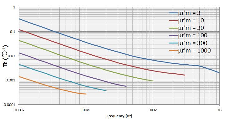
41 41 Keysight E4991B Impedance Analyzer - Data Sheet Typical Effects of Temperature Change on Permeability Measurement Accuracy (continued) Figure 57. Typical frequency characteristics of temperature coefficient of µ' r (at F = 0.5 mm) Figure 56. Typical frequency characteristics of temperature coefficient of µ' r (at F = 3 mm) Figure 59. Typical frequency characteristics of temperature coefficient of µ' r (at F = 10 mm)

 894 4414 Brazil 55 11 3351 7010 Mexico 001 800 254 2440 United States (800) 829 4444 KEYSIGHT SERVICES From Hewlett-Packard to Agilent to Keysight mykeysight")

42 42 Keysight E4991B Impedance Analyzer - Data Sheet Evolving Our unique combination of hardware, software, support, and people can help you reach your next breakthrough. We are unlocking the future of technology. For more information on Keysight Technologies products, applications or services, please contact your local Keysight office. The complete list is available at: Americas Canada (877) Brazil Mexico United States (800) KEYSIGHT SERVICES From Hewlett-Packard to Agilent to Keysight mykeysight A personalized view into the information most relevant to you. Keysight Infoline Keysight s insight to best in class information management. Free access to your Keysight equipment company reports and e-library. Keysight Services Our deep offering in design, test, and measurement services deploys an industry-leading array of people, processes, and tools. The result? We help you implement new technologies and engineer improved processes that lower costs. Three-Year Warranty Keysight s committed to superior product quality and lower total cost of ownership. Keysight is the only test and measurement company with three-year warranty standard on all instruments, worldwide. And, we provide a one-year warranty on many accessories, calibration devices, systems and custom products. Keysight Assurance Plans Up to ten years of protection and no budgetary surprises to ensure your instruments are operating to specification, so you can rely on accurate measurements. Keysight Channel Partners Get the best of both worlds: Keysight s measurement expertise and product breadth, combined with channel partner convenience. Asia Pacific Australia China Hong Kong India Japan 0120 (421) 345 Korea Malaysia Singapore Taiwan Other AP Countries (65) Europe & Middle East Austria Belgium Finland France Germany Ireland Israel Italy Luxembourg Netherlands Russia Spain Sweden Switzerland Opt. 1 (DE) Opt. 2 (FR) Opt. 3 (IT) United Kingdom For other unlisted countries: (BP ) DEKRA Certified ISO9001 Quality Management System Keysight Technologies, Inc. DEKRA Certified ISO 9001:2015 Quality Management System This information is subject to change without notice. Keysight Technologies, 2015, 2016 Published in USA, October 20, EN
Keysight Technologies E4991B Impedance Analyzer
 Keysight Technologies E4991B Impedance Analyzer 1 MHz to 500 MHz/1 GHz/3 GHz Data Sheet Deinitions Speciication (spec.) Warranted performance. All specifications apply at 23 C ± 5 C unless otherwise stated,
E4991B Impedance Analyzer
 DATA SHEET E4991B Impedance Analyzer 1 MHz to 500 MHz/1 GHz/3 GHz Definitions Specification (spec.) Warranted performance. All specifications apply at 23 C ± 5 C unless otherwise stated, and 30 minutes
Keysight E5063A ENA Series Network Analyzer
 Keysight E5063A ENA Series Network Analyzer 100 khz to 500 M/1.5 G/3 G/4.5 G/6.5 G/8.5 G/14 G/18 GHz Data Sheet 02 Keysight E5063A ENA Series Network Analyzer - Data Sheet Deinitions Speciication (spec.):
Keysight E5063A ENA Series Network Analyzer
 Keysight E5063A ENA Series Network Analyzer 100 khz to 4.5/8.5/18 GHzz Data Sheet Deinitions Specification (spec.): Warranted performance. All speciications apply at 23 ºC (± 5 ºC), unless otherwise stated,
DATA SHEET. E4982A LCR Meter. 1 MHz to 300 MHz/500 MHz/1 GHz/3 GHz
 DATA SHEET E4982A LCR Meter 1 MHz to 300 MHz/500 MHz/1 GHz/3 GHz Specification (spec.) Warranted performance. All specifications apply at 23 C ± 5 C unless otherwise stated, and 30 minutes after the instrument
Keysight E5063A ENA Vector Network Analyzer
 Keysight E5063A ENA Vector Network Analyzer 100 khz to 500 M/1.5 G/3 G/4.5 G/6.5 G/8.5 G/14 G/18 GHz Data Sheet 2 Keysight E5063A ENA Vector Network Analyzer - Data Sheet Table of Contents Definitions
Keysight Technologies E4990A Impedance Analyzer
 Keysight Technologies E4990A Impedance Analyzer 20 Hz to 10/20/30/50/120 MHz Data Sheet 02 Keysight E4990A Impedance Analyzer 20 Hz to 10/20/30/50/120 MHz - Data Sheet This document provides technical
Agilent. E5071C ENA Network Analyzer 9 khz to 4.5/6.5/8.5 GHz 100 khz to 4.5/6.5/8.5 GHz (with bias tees) 300 khz to 14/20 GHz (with bias tees)
 300 khz to 14/20 GHz (with bias tees)") Agilent E5071C ENA Network Analyzer 9 khz to 4.5/6.5/8.5 GHz 0 khz to 4.5/6.5/8.5 GHz (with bias tees) 300 khz to 14/20 GHz (with bias tees) E5091A Multiport Test Set E5092A Configurable Multiport Test
Agilent E5071C ENA Network Analyzer 9 khz to 4.5/6.5/8.5 GHz 0 khz to 4.5/6.5/8.5 GHz (with bias tees) 300 khz to 14/20 GHz (with bias tees) E5091A Multiport Test Set E5092A Configurable Multiport Test
Keysight Technologies E5080A ENA Vector Network Analyzer. E5092A Configurable Multiport Test Set
 Keysight Technologies E5080A ENA Vector Network Analyzer - 9 khz to 4.5/6.5/9 GHz E5092A Configurable Multiport Test Set Data Sheet 02 Keysight E5080A ENA Vector Network Analyzer, E5092A Configurable Multiport
Keysight Technologies 87405C 100 MHz to 18 GHz Preamplifier. Technical Overview
 Keysight Technologies 8745C 1 MHz to 18 GHz Preamplifier Technical Overview 2 Keysight 8745C 1 MHz to 18 GHz Preamplifier Technical Overview Introduction The Keysight Technologies, Inc. 8745C preamplifier
Keysight Technologies Waveguide Power Sensors. Data Sheet
 Keysight Technologies Waveguide Power Sensors Data Sheet 02 Keysight Waveguide Power Sensors - Data Sheet Make accurate and reliable measurements in the 50 to 110 GHz frequency range with Keysight s family
Keysight E5063A ENA Series Network Analyzer
 Keysight E5063A ENA Series Network Analyzer 100 khz to 500 M/1.5 G/3 G/4.5 G/6.5 G/8.5 G/14 G/18 GHz Configuration Guide 02 Keysight E5063A ENA Series Network Analyzer - Configuration Guide Ordering Guide
Keysight Technologies E5071C ENA Vector Network Analyzer. E5092A Configurable Multiport Test Set
 Keysight Technologies E5071C ENA Vector Network Analyzer 9 khz to 4.5/6.5/8.5 GHz 100 khz to 4.5/6.5/8.5 GHz (with bias tees) 300 khz to 14/20 GHz (with bias tees) E5092A Configurable Multiport Test Set
Keysight Technologies E5072A ENA Series Network Analyzer 30 khz to 4.5/8.5 GHz. Data Sheet
 Keysight Technologies E572A ENA Series Network Analyzer 3 khz to 4.5/8.5 GHz Data Sheet 2 Keysight E572A ENA Series Network Analyze 3 khz to 4.5/8.5 GHz - Data Sheet Options This document provides technical
Keysight Technologies P9400A/C Solid State PIN Diode Transfer Switches
 Keysight Technologies P9400A/C Solid State PIN Diode Transfer Switches P9400A 100 MHz to 8 GHz PIN transfer switch P9400C 100 MHz to 18 GHz PIN transfer switch Technical Overview Key Features Minimize
Keysight Technologies 8490G Coaxial Attenuators. Technical Overview
 Keysight Technologies 8490G Coaxial Attenuators Technical Overview Introduction Key Specifications Maximize your operating frequency range for DC to 67 GHz application Minimize your measurement uncertainty
Keysight N9310A RF Signal Generator
 Keysight N9310A RF Signal Generator 9 khz to 3.0 GHz Data Sheet 02 Keysight N9310A RF Signal Generator - Data Sheet Definitions and Conditions Specifications describe the performance of parameters that
Keysight Technologies N2792A/N2818A 200 MHz and N2793A/N2819A 800 MHz Differential Probes. Data Sheet
 Keysight Technologies N2792A/N2818A 200 MHz and N2793A/N2819A 800 MHz Differential Probes Data Sheet Introduction The Keysight Technologies, Inc. N2792A/93A and N2818A/19A differential probes provide the
Agilent. E5071C ENA Network Analyzer 9 khz to 4.5/6.5/8.5 GHz 100 khz to 4.5/6.5/8.5 GHz (with bias tees) 300 khz to 14/20 GHz (with bias tees)
 300 khz to 14/20 GHz (with bias tees)") Agilent E571C ENA Network Analyzer 9 khz to 4.5/6.5/8.5 GHz khz to 4.5/6.5/8.5 GHz (with bias tees) 3 khz to 14/2 GHz (with bias tees) E592A Configurable Multiport Test Set Data Sheet Table of Contents
Agilent E571C ENA Network Analyzer 9 khz to 4.5/6.5/8.5 GHz khz to 4.5/6.5/8.5 GHz (with bias tees) 3 khz to 14/2 GHz (with bias tees) E592A Configurable Multiport Test Set Data Sheet Table of Contents
Keysight Technologies
 Keysight Technologies Easily Create Power Supply Output Sequences with Data Logging Application Brief 02 Keysight Easily Create Power Supply Output Sequences with Data Logging - Application Brief Why is
Keysight Technologies E5072A ENA Series Network Analyzer 30 khz to 4.5 /8.5 GHz. Data Sheet
 Keysight Technologies E572A ENA Series Network Analyzer 3 khz to 4.5 /8.5 GHz Data Sheet Options This document provides technical speciications for the E572A ENA network analyzer. E572A-245 E572A-285 2-port
Keysight Technologies Using an External Trigger to Generate Pulses with the B2960A
 Keysight Technologies Using an External Trigger to Generate Pulses with the B2960A B2960A 6.5 Digit Low Noise Power Source Demo Guide 02 Keysight Using an External Trigger to Generate Pulses with the B2960A
Keysight Technologies N9398C/F/G and N9399C/F DC Block. Technical Overview
 Keysight Technologies N9398C/F/G and N9399C/F DC Block Technical Overview Introduction Key Features Maximize your operating range - 26.5, 50 or 67 GHz Improve calibration accuracy with exceptional return
Keysight 8474B/C/E Planar-Doped Barrier Diode Detectors 0.01 to 50 GHz. Data Sheet
 Keysight 8474B/C/E Planar-Doped Barrier Diode Detectors.1 to 5 GHz Data Sheet Introduction Features and Description Exceptional flatness Broadband from.1 to 5 GHz Extremely temperature stable Environmentally
Keysight Technologies N4985A System Amplifiers
 Keysight Technologies N4985A System Amplifiers Data Sheet N4985A-P15 10 MHz to 50 GHz N4985A-P25 2 to 50 GHz N4985A-S30 100 khz to 30 GHz N4985A-S50 100 khz to 50 GHz Exceptional gain and power performance
Keysight Technologies USB Preamplifiers
 Keysight Technologies USB Preamplifiers U77/A 1 MHz to 4 GHz U77/C 1 MHz to 6. GHz U77/F to GHz Technical Overview Keysight USB Preamplifiers U77A/C/F - Technical Overview Key Features and Benefits Automatic
Keysight Technologies Electronic Calibration (ECal) Modules for Vector Network Analyzers
 Modules for Vector Network Analyzers") Keysight Technologies Electronic Calibration (ECal) Modules for Vector Network Analyzers N4690 Series, 2-port Microwave ECal 85090 Series, 2-port RF ECal N4430 Series, 4-port ECal N7550 Series, 2-port
Keysight Technologies Electronic Calibration (ECal) Modules for Vector Network Analyzers N4690 Series, 2-port Microwave ECal 85090 Series, 2-port RF ECal N4430 Series, 4-port ECal N7550 Series, 2-port
Keysight Technologies 87405C 100 MHz to 18 GHz Preamplifier. Technical Overview
 Keysight Technologies 8745C 1 MHz to 18 GHz Preamplifier Technical Overview 2 Keysight 8745C 1 MHz to 18 GHz Preamplifier Technical Overview Introduction The Keysight Technologies, Inc. 8745C preamplifier
Keysight Technologies 423B, 8470B, 8472B, 8473B/C Low Barrier Schottky Diode Detectors
 Keysight Technologies 423B, 8470B, 8472B, 8473B/C Low Barrier Schottky Diode Detectors Keysight 423B Data Sheet Keysight 8470B Keysight 8472B Keysight 8473B Keysight 8473C Introduction Excellent broadband
Keysight Technologies
 Keysight Technologies Easily Create Power Supply Output Sequences with Data Logging Application Brief 02 Keysight Easily Create Power Supply Output Sequences with Data Logging - Application Brief Why is
Keysight Technologies Power of Impedance Analyzer
 Keysight Technologies Power of Impedance Analyzer - Comparison to Network Analyzer Application Note Uncover real characteristics Introduction Keysight s impedance analyzers are the only instruments on
Introduction. Part 1. Introduction...2
 Keysight Technologies Simple Scalar Network Analysis of Frequency Converter Devices using the U2000 USB Power Sensor Series with the ENA Network Analyzer Application Note Introduction This application
Keysight Technologies How to Read Your Power Supply s Data Sheet. Application Note
 Keysight Technologies How to Read Your Power Supply s Data Sheet Application Note Introduction If you are designing electronic devices and you need to power up a design for the first time, there s a good
Agilent E5072A ENA Series Network Analyzer
 Agilent E572A ENA Series Network Analyzer 3 khz to 4.5 /8.5 GHz Data Sheet Options This document provides technical specifications for the E572A ENA network analyzer. E572A-245 E572A-285 2-port with configurable
Keysight E5063A ENA Vector Network Analyzer
 Keysight E5063A ENA Vector Network Analyzer 100 khz to 500 M/1.5 G/3 G/4.5 G/6.5 G/8.5 G/14 G/18 GHz Configuration Guide 02 Keysight E5063A ENA Vector Network Analyzer - Configuration Guide Ordering Guide
Artisan Technology Group is your source for quality new and certified-used/pre-owned equipment
 Artisan Technology Group is your source for quality new and certified-used/pre-owned equipment FAST SHIPPING AND DELIVERY TENS OF THOUSANDS OF IN-STOCK ITEMS EQUIPMENT DEMOS HUNDREDS OF MANUFACTURERS SUPPORTED
Keysight N9320B RF Spectrum Analyzer
 Keysight N9320B RF Spectrum Analyzer 9 khz to 3.0 GHz Data Sheet 02 Keysight N9320B RF Spectrum Analyzer - Data Sheet Definitions and Conditions Specifications describe the performance of parameters and
E5071C ENA Vector Network Analyzer. E5092A Configurable Multiport Test Set
 DATA SHEET E5071C ENA Vector Network Analyzer 9 khz to 4.5/6.5/8.5 GHz 100 khz to 4.5/6.5/8.5 GHz (with bias tees) 300 khz to 14/20 GHz (with bias tees) E5092A Configurable Multiport Test Set Table of
E4990A Impedance Analyzer 20 Hz to 10/20/30/50/120 MHz DATA SHEET
 E4990A Impedance Analyzer 20 Hz to 10/20/30/50/120 MHz DATA SHEET This document provides technical specifications for the E4990A. Options The following options are available. E4990A-120 20 Hz to 120 MHz
Keysight Technologies N1918A Power Analysis Manager and U2000 Series USB Power Sensors. Demo Guide
 Keysight Technologies N1918A Power Analysis Manager and U2000 Series USB Power Sensors Demo Guide Introduction This demonstration guide helps you to get familiar with the basic setup and configuration
Keysight DSOXT3FRA/DSOX4FRA/DSOX6FRA Frequency Response Analyzer (FRA) Option
 Option") Keysight DSOXT3FRA/DSOX4FRA/DSOX6FRA Frequency Response Analyzer (FRA) Option For Keysight 3000T, 4000A, and 6000A X-Series Oscilloscopes Data Sheet Introduction Frequency Response Analysis (FRA) is often
Keysight DSOXT3FRA/DSOX4FRA/DSOX6FRA Frequency Response Analyzer (FRA) Option For Keysight 3000T, 4000A, and 6000A X-Series Oscilloscopes Data Sheet Introduction Frequency Response Analysis (FRA) is often
Agilent. E5071C ENA Network Analyzer 9 khz to 4.5/6.5/8.5 GHz 100 khz to 4.5/6.5/8.5 GHz (with bias tees) 300 khz to 14/20 GHz (with bias tees)
 300 khz to 14/20 GHz (with bias tees)") Agilent E571C ENA Network Analyzer 9 khz to 4.5/6.5/8.5 GHz khz to 4.5/6.5/8.5 GHz (with bias tees) 3 khz to 14/2 GHz (with bias tees) E592A Configurable Multiport Test Set Data Sheet Table of Contents
Agilent E571C ENA Network Analyzer 9 khz to 4.5/6.5/8.5 GHz khz to 4.5/6.5/8.5 GHz (with bias tees) 3 khz to 14/2 GHz (with bias tees) E592A Configurable Multiport Test Set Data Sheet Table of Contents
Agilent. E5071C ENA Network Analyzer 9 khz to 4.5/6.5/8.5 GHz 100 khz to 4.5/6.5/8.5 GHz (with bias tees) 300 khz to 14/20 GHz (with bias tees)
 300 khz to 14/20 GHz (with bias tees)") Agilent E5071C ENA Network Analyzer 9 khz to 4.5/6.5/8.5 GHz 100 khz to 4.5/6.5/8.5 GHz (with bias tees) 300 khz to 14/20 GHz (with bias tees) E5092A Configurable Multiport Test Set Data Sheet Table of
Agilent E5071C ENA Network Analyzer 9 khz to 4.5/6.5/8.5 GHz 100 khz to 4.5/6.5/8.5 GHz (with bias tees) 300 khz to 14/20 GHz (with bias tees) E5092A Configurable Multiport Test Set Data Sheet Table of
Keysight Technologies Using a Network and Impedance Analyzer to Evaluate MHz RFID Tags and Readers/Writers
 Keysight Technologies Using a Network and Impedance Analyzer to Evaluate 13.56 MHz RFID Tags and Readers/Writers Application Note L C R f 0 = 2 1 π L C Introduction RFIDs, also called non-contact IC cards
Keysight Technologies Phase Noise X-Series Measurement Application
 Keysight Technologies Phase Noise X-Series Measurement Application N9068C Technical Overview Phase noise measurements with log plot and spot frequency views Spectrum and IQ waveform monitoring for quick
Agilent ENA 2 and 4 Port RF Network Analyzers
 Agilent ENA 2 and 4 Port RF Network Analyzers Data Sheet E5071C-240/440 9 khz to 4.5 GHz E5071C-245/445 0 khz to 4.5 GHz (with bias-tees) E5071C-280/480 9 khz to 8.5 GHz E5071C-285/485 0 khz to 8.5 GHz
Introduction. Part 1. Introduction...2
 Keysight Technologies Simple Scalar Network Analysis of Frequency Converter Devices using the U2000 USB Power Sensor Series with the ENA Network Analyzer Application Note Introduction This application
Keysight Technologies Differences in Application Between Power Dividers and Power Splitters. Application Note
 Keysight Technologies Differences in Application Between Dividers and Splitters Application Note 02 Keysight Differences in Application Between Dividers and Splitters Application Note Introduction dividers
Keysight Technologies Accurate Evaluation of MEMS Piezoelectric Sensors and Actuators Using the E4990A Impedance Analyzer.
 Keysight Technologies Accurate Evaluation of MEMS Piezoelectric Sensors and Actuators Using the E4990A Impedance Analyzer Application Note Introduction Excellent impedance measurement accuracy and repeatability
Keysight Technologies E5071C ENA Network Analyzer
 Keysight Technologies E5071C ENA Network Analyzer 9 khz to 4.5/6.5/8.5 GHz 100 khz to 4.5/6.5/8.5 GHz (with bias tees) 300 khz to 14/20 GHz (with bias tees) E5092A Conigurable Multiport Test Set Data Sheet
Keysight Technologies, Inc. UWB Antenna Measurements with the 20 GHz E5071C ENA Network Analyzer. Application Note
 Keysight Technologies, Inc. UWB Antenna Measurements with the 20 GHz E5071C ENA Network Analyzer Application Note Introduction Ultra-wideband (UWB) is a rapidly growing technology that is used to transmit
Keysight Technologies Migrating from the 4268A/4288A Capacitance Meter to the E4981A Capacitance Meter. Technical Overview
 Keysight Technologies Migrating from the 4268A/4288A Capacitance Meter to the E4981A Capacitance Meter Technical Overview E4981A Capacitance Meter The E4981A capacitance meter provides the best combination
Keysight Technologies Making Field Effect Transistor Characterization Using SMU
 Keysight Technologies Making Field Effect Transistor Characterization Using SMU B2900A Precision Source/Measure Unit Demo Guide Introduction The Keysight s B2900A Series Precision Source/Measure Unit (SMU)
Keysight Technologies 85072A 10-GHz Split Cylinder Resonator. Technical Overview
 Keysight Technologies 85072A 10-GHz Split Cylinder Resonator Technical Overview 02 Keysight 85072A 10-GHz Split Cylinder Resonator - Technical Overview Part of the complete turn-key solution for the IPC
Keysight Technologies 1 mw 50 MHz Power Reference Measurement with the N432A Thermistor Power Meter. Application Note
 Keysight Technologies 1 mw 50 MHz Power Reference Measurement with the N432A Thermistor Power Meter Application Note Introduction This application note explains the application procedure for using the
Keysight Technologies N4983A Multiplexer and Demultiplexer. Data Sheet
 Keysight Technologies N4983A Multiplexer and Demultiplexer Data Sheet 02 Keysight N4983A Multiplexer and Demultiplexer - Data Sheet N4983A-M40 44 Gb/s multiplexer Features Wide operating range, 2 to 44
Keysight Technologies E4980A Precision LCR Meter
 Keysight Technologies E4980A Precision LCR Meter 20 Hz to 2 MHz An industry standard LCR meter 02 Keysight E4980A Precision LCR Meter Brochure An Industry Standard LCR Meter Keysight Technologies E4980A
Keysight Technologies Migrating Balanced Measurements from the
 Keysight Technologies Migrating Balanced Measurements from the HP 8903B to the Keysight U8903A Audio Analyzer Application Note 02 Keysight Migrating Balanced Measurements from the HP 8903B to the U8903A
Keysight Technologies Improving Test Efficiency of MEMS Electrostatic Actuators Using the E4980A Precision LCR Meter.
 Keysight Technologies Improving Test Efficiency of MEMS Electrostatic Actuators Using the E4980A Precision LCR Meter Application Note Introduction Highly accurate and repeatable measurements DC bias function
Keysight Technologies A comparison of Keysight Network Analyzers for Applications < 3 GHz. Selection Guide
 Keysight Technologies A comparison of Keysight Network Analyzers for Applications < 3 GHz Selection Guide N9923A FieldFox RF Vector Network Analyzer, 2 MHz to 4/6 GHz Keysight Technologies, Inc. handheld
Keysight Technologies Accurate Capacitance Characterization at the Wafer Level
 Keysight Technologies Accurate Capacitance Characterization at the Wafer Level 4080 Series Parametric Test Systems Application Note Introduction The continuing trend of decreasing device geometries of
Keysight Technologies Improving the Test Efficiency of MEMS Capacitive Sensors Using the E4980A Precision LCR Meter.
 Keysight Technologies Improving the Test Efficiency of MEMS Capacitive Sensors Using the E4980A Precision LCR Meter Application Note Introduction Exceptional accuracy and repeatability DC bias function
Keysight Technologies N9398C/F/G and N9399C/F DC Block. Technical Overview
 Keysight Technologies N9398C/F/G and N9399C/F DC Block Technical Overview Introduction Key Features Maximize your operating range - 26.5, 50 or 67 GHz Improve calibration accuracy with exceptional return
Keysight Technologies N2750A/51A/52A InfiniiMode Differential Active Probes. Data Sheet
 Keysight Technologies N2750A/51A/52A InfiniiMode Differential Active Probes Data Sheet 02 Keysight N2750A/51A/52A InfiniiMode Differential Active Probes Data Sheet Key Features Measurement versatility
Keysight M9485A PXIe Multiport Vector Network Analyzer
 Keysight M9485A PXIe Multiport Vector Network Analyzer 02 Keysight M9485A PXIe Multiport Vector Network Analyzer - Brochure High-Performance PXI Multiport Vector Network Analyzer (VNA) Innovative solution
Keysight Technologies N2790A 100 MHz, N2791A 25 MHz and N2891A 70 MHz High-voltage Differential Probes. Data Sheet
 Keysight Technologies N2790A 100 MHz, N2791A 25 MHz and N2891A 70 MHz High-voltage Differential Probes Data Sheet 02 Keysight N2790A 100 MHz, N2791A 25 MHz and N2891A 70 MHz High-voltage Differential Probes
Keysight Technologies N6850A Broadband Omnidirectional Antenna. Data Sheet
 Keysight Technologies N6850A Broadband Omnidirectional Antenna Data Sheet 02 Keysight N6850A Broadband Omnidirectional Antenna - Data Sheet Industries and Applications Spectrum monitoring and signal location,
Keysight Technologies Network Analyzer Measurements: Filter and Amplifier Examples. Application Note
 Keysight Technologies Network Analyzer Measurements: Filter and Amplifier Examples Application Note Introduction Both the magnitude and phase behavior of a component are critical to the performance of
Keysight 8762F Coaxial Switch 75 ohm
 Keysight 8762F Coaxial Switch 75 ohm Technical Overview DC to 4 GHz Exceptional repeatability over 1 million cycle life Excellent isolation The 8762F brings a new standard of performance to 75 ohm coaxial
Keysight Technologies U9391C/F/G Comb Generators. U9391C (10 MHz to 26.5 GHz) U9391F (10 MHz to 50 GHz) U9391G (10 MHz to 67 GHz) Technical Overview
 U9391F (10 MHz to 50 GHz) U9391G (10 MHz to 67 GHz) Technical Overview") Keysight Technologies U9391C/F/G Comb Generators U9391C (10 MHz to 26.5 GHz) U9391F (10 MHz to 50 GHz) U9391G (10 MHz to 67 GHz) Technical Overview Key Features Excellent amplitude and phase flatness enable
Keysight Technologies U9391C/F/G Comb Generators U9391C (10 MHz to 26.5 GHz) U9391F (10 MHz to 50 GHz) U9391G (10 MHz to 67 GHz) Technical Overview Key Features Excellent amplitude and phase flatness enable
Keysight Technologies Measuring Low Current Consumption with a Digital Multimeter
 Keysight Technologies Measuring Low Current Consumption with a Digital Multimeter Application Brief Test Challenges: Characterizing the power consumption of a battery powered device Testing the current
Keysight N9320B RF Spectrum Analyzer
 Keysight N9320B RF Spectrum Analyzer 9 khz to 3.0 GHz Data Sheet 02 Keysight N9320B RF Spectrum Analyzer - Data Sheet Definitions and Conditions Specifications describe the performance of parameters covered
Keysight Technologies VOR and ILS Radio Navigation Receiver Test Using Option 302 for Keysight Signal Sources. Application Note
 Keysight Technologies VOR and ILS Radio Navigation Receiver Test Using Option 302 for Keysight Signal Sources Application Note Introduction The Keysight X-series (EXG and MXG) analog and vector signal
Keysight N2806A Calibration Pulse Generator The world s fastest differential pulse generator. Data Sheet
 Keysight N2806A Calibration Pulse Generator The world s fastest differential pulse generator Data Sheet Introduction Sub-7 ps fall time (90%-10%) Sub-9 ps rise time (10%-90%) Fully differential output
Keysight Technologies Measuring Group Delay of Frequency Converters with Embedded Local Oscillators. Application Note
 Keysight Technologies Measuring Group Delay of Frequency Converters with Embedded Local Oscillators Application Note Introduction Mixers and frequency converters lie at the heart of wireless and satellite
Keysight Technologies 4285A Precision LCR Meter. Data Sheet
 Keysight Technologies 4285A Precision LCR Meter Data Sheet 02 Keysight 4285A Precision LCR Meter Data Sheet Specifications The complete Keysight Technologies, Inc. 4285A specifications are listed below.
Keysight Technologies RF & Microwave Attenuators. Performance you can count on
 Keysight Technologies RF & Microwave Attenuators Performance you can count on Key Features High reliability and exceptional repeatability reduce downtime Excellent RF specifications optimize test system
Keysight Measuring High Impedance Sources Using the U8903B Audio Analyzer. Application Note
 Keysight Measuring High Impedance Sources Using the U8903B Audio Analyzer Application Note Introduction This note details the input impedance of the U8903B Audio Analyzer, and shows that this needs to
Keysight Technologies Split Post Dielectric Resonators for Dielectric Measurements of Substrates. Application Note
 Keysight Technologies Split Post Dielectric Resonators for Dielectric Measurements of Substrates Application Note Introduction The Keysight Technologies, Inc. split post dielectric resonator (SPDR) provides
Keysight Technologies U1210 Series Handheld Clamp Meters
 Keysight Technologies U1210 Series Handheld Clamp Meters Handle big currents more safely Data Sheet Introduction Measurements of electrical distribution cables can be challenging and risky. For cables
Keysight HMMC-1002 DC 50 GHz Variable Attenuator
 Keysight HMMC-1002 DC 50 GHz Variable Attenuator 1GG7-8001 Data Sheet Features Specified frequency range: DC to 26.5 GHz Return loss: 10 db Minimum attenuation: 2.0 db Maximum attenuation: 30.0 db 02 Keysight
Keysight Technologies N9310A RF Signal Generator
 Keysight Technologies N9310A RF Signal Generator 02 Keysight N9310A RF Signal Generator Brochure All the capability and reliability of a Keysight instrument you need at a price you ve always wanted Reliable
Agilent ENA Series 2, 3 and 4 Port RF Network Analyzers E5070A 300 khz to 3 GHz E5071A 300 khz to 8.5 GHz E5091A Multiport Test Set.
 Agilent ENA Series 2, 3 and 4 Port RF Network Analyzers E5070A 300 khz to 3 GHz E5071A 300 khz to 8.5 GHz E5091A Multiport Test Set Data Sheet Definitions All specifications apply over a 5 C to 40 C range
Keysight Technologies, Inc. Overcome PCB Loss and Deliver a Clean Eye to Your DUT Using Multi-tap De-emphasis
 Keysight Technologies, Inc. Overcome PCB Loss and Deliver a Clean Eye to Your DUT Using Multi-tap De-emphasis Application Brief Introduction Keysight Technologies, Inc. announces a new 32 Gb/s pattern
Keysight Technologies Active Differential Probes U1818A 100 khz to 7 GHz U1818B 100 khz to 12 GHz. Technical Overview
 Keysight Technologies Active Differential Probes U1818A 100 khz to 7 GHz U1818B 100 khz to 12 GHz Technical Overview Introduction The Keysight Technologies, Inc. active differential probes provide high
Keysight Technologies Accurate NBTI Characterization Using Timing-on-the-fly Sampling Mode. Application Note
 Keysight Technologies Accurate NBTI Characterization Using Timing-on-the-fly Sampling Mode Application Note Introduction Keysight B1500A Semiconductor Device Analyzer Controlled dynamic recovery with 100
Keysight Technologies DSOX3PWR/DSOX4PWR/DSOX6PWR Power Measurement Options
 Keysight Technologies DSOX3PWR/DSOX4PWR/DSOX6PWR Power Measurement Options Data Sheet For InfiniiVision 3000, 4000 and 6000 X-Series Oscilloscopes Achieve cost-effective analysis of your switching mode
Keysight Technologies PXI Vector Network Analyzer Series. Drive down the size of test
 Keysight Technologies PXI Vector Network Analyzer Series Drive down the size of test 02 Keysight PXI Vector Network Analyzer Series - Brochure Full Two-Port VNA that Fits in Just One Slot When you need
Keysight Technologies Precise Low Resistance Measurements Using the B2961A and 34420A
 Keysight Technologies Precise Low Resistance Measurements Using the B2961A and 34420A B2961A/B2962A 6.5 Digit Low Noise Power Source Application Note Introduction Resistance measurement is one of the most
Keysight Technologies Making Current-Voltage Measurement Using SMU
 Keysight Technologies Making Current-Voltage Measurement Using SMU Keysight B2901A/02A/11A/12A Precision Source/Measure Unit Demonstration Guide Introduction The Keysight Technologies, Inc. B2901A/02A/11A/12A
Keysight Technologies Simultaneous Measurements with a Digital Multimeter
 Keysight Technologies Simultaneous Measurements with a Digital Multimeter Application Brief Test Challenges: Making more confident measurements Making dual measurements in less time 02 Keysight Simultaneous
Keysight Technologies E4990A Impedance Analyzer. 20 Hz to 10/20/30/50/120 MHz
 Keysight Technologies E4990A Impedance Analyzer 20 Hz to 10/20/30/50/120 MHz 02 Keysight E4990A Impedance Analyzer - Brochure Keysight Impedance Analyzer Series Achieve success with the industry standard
Keysight Technologies Direct Power MOSFET Capacitance Measurement at 3000 V
 Keysight Technologies Direct Power MOSFET Capacitance Measurement at 3000 V B1505A Power Device Analyzer/Curve Tracer Application Note Introduction The input, output and reverse transfer capacitance of
Keysight Technologies 34450A Multimeter 5.5 Digit Dual Display, Benchtop DMM. Data Sheet
 Keysight Technologies 34450A Multimeter 5.5 Digit Dual Display, Benchtop DMM Data Sheet 02 Keysight 34450A Multimeter 5.5 Digit Dual Display, Benchtop DMM Data Sheet Features Fast reading speed of up to
Keysight Technologies Characterizing Random Noise in CMOS Image Sensors
 Keysight Technologies Characterizing Random Noise in CMOS Image Sensors RTS noise measurement using the B1500A s WGFMU Module Application Note Introduction A random telegraph signal (RTS) is a random process
Keysight M940xA PXIe Optical Extenders for Instrumentation. Data Sheet
 Keysight M940xA PXIe Optical Extenders for Instrumentation Data Sheet Overview Introduction The Keysight Technologies, Inc. Optical Extenders for Instruments can transmit your RF or Microwave signal without
Keysight Technologies U9391C/F/G Comb Generators. U9391C (10 MHz to 26.5 GHz) U9391F (10 MHz to 50 GHz) U9391G (10 MHz to 67 GHz) Technical Overview
 U9391F (10 MHz to 50 GHz) U9391G (10 MHz to 67 GHz) Technical Overview") Keysight Technologies U9391C/F/G Comb Generators U9391C (10 MHz to 26.5 GHz) U9391F (10 MHz to 50 GHz) U9391G (10 MHz to 67 GHz) Technical Overview 2 Keysight U9391C/F/G Comb Generators - Technical Overview
Keysight Technologies U9391C/F/G Comb Generators U9391C (10 MHz to 26.5 GHz) U9391F (10 MHz to 50 GHz) U9391G (10 MHz to 67 GHz) Technical Overview 2 Keysight U9391C/F/G Comb Generators - Technical Overview
Keysight N9311X RF and Microwave Accessory Kit for Low-cost Handheld and Benchtop Solutions. Technical Overview
 Keysight N9311X RF and Microwave Accessory Kit for Low-cost Handheld and Benchtop Solutions Technical Overview 02 Keysight N9311X RF and Microwave Accessory Kit for Low-cost Handheld and Benchtop Solutions
Keysight N8836A PAM-4 Measurement Application For Infiniium S-Series, 90000A, V-Series, X-Series, Q-Series, and Z-Series Oscilloscopes
 Keysight N8836A PAM-4 Measurement Application For S-Series, 90000A, V-Series, 90000 X-Series, 90000 Q-Series, and Z-Series Oscilloscopes Characterize electrical pulse amplitude modulated (PAM) signals
Keysight Technologies NFA Noise Figure Analyzer. Configuration Guide
 Keysight Technologies NFA Noise Figure Analyzer Configuration Guide Noise Figure Analyzer Overview Over 50 years of noise figure leadership Dedicated Noise Figure Analyzer Hard specifications to 26.5 GHz