Radar Systems on Shortwave
|
|
|
- Juniper Heath
- 6 years ago
- Views:
Transcription
 2.1 Basic Infos 2.2 OTHR Australia - JORN 2.")
1 Radar Systems on Shortwave observed and compiled by DK2OM Wolf Hadel Coordinator IARUMS Region 1 Copyright DK2OM State: April 2012 Contents: 1. Ionosphere / Troposhere Diagnostic Radars 1.1 HAARP - USA 1.2 Ionosondes 1.3 Superdarn 1.4 SURA - Russia 1.5 Tiger-Radar Australia 1.6 SOUSY Svalbard Radar 2. Over The Horizon Radars (OTHR) 2.1 Basic Infos 2.2 OTHR Australia - JORN 2.3 OTHR China 2.4 OTHR Cyprus 2.5 OTHR Denmark 2.6 OTHR France - Nostradamus 2.7 OTHR Iran 2.8 OTHR Israel 2.9 OTHR Romania 2.10 OTHR Russia 2.11 OTHR Turkey 2.12 OTHR UK 2.13 OTHR Ukraine 2.14 OTHR USA 2.15 OTHR unknown 3. Ocean Wave and Coastal Radars 3.1 Codar- and other Coastal Systems 3.2 WERA Germany Introduction The shortwaves are crowded by many kinds of Radars. Radars are often disturbing Amateurradio, Weatherfax, Military traffic and other services, too. This collection is only a small overview! We are expecting more systems with partly very complicate parameters and purposes. Observations with SDR-Receivers (like Perseus) and analysis by the sophisticated Wavecom products are often helpful. Other equipments, which are used by laboratories are much too expensive for Radioamateurs. All screenshots with W40PC, W61PC (Wavecom), Gram50 and Perseus: DK2OM All other sources are exactly mentioned!
 source: http://www.haarp.alaska.")
2 1. Ionosphere Diagnostic Radars Such kinds of Radar have been developed to study the structures and the properties of the Ionosphere. 1.1 HAARP USA (High Frequency Active Auroral Research Program) source:


3 1.2 Ionosondes Ionosondes are examinating ionospheric physics, especially reflections for military and other purposes. Very fast sweeps are running over large frequency ranges during few seconds. source: Ionosondes observed by DK2OM: slow type of ionosonde fast running system
4 Ionogram from Juliusruh Germany Ionogram from Pruhonice Czech Republic


5 How to read a ionogram source: The function of a continuous chirp signal sounder : source:


6 1.3 Superdarn SuperDARN stands for Super Dual Auroral Radar Network. Northern hemisphere exploration. source: Superdarnsignals above khz observed by DK2OM: soundfile:
 Russia - close")

7 1.4 SURA (HAARP like Facility) Russia - close to Nizhny Novgorod source:
 operated by ten nations to provide simultaneous coverage of both")

8 1.5 Tiger-Radar Australia New Zealand source: TIGER is part of an international network of similar HF radars called SuperDARN (Super Dual Auroral Radar Network) operated by ten nations to provide simultaneous coverage of both southern and northern polar regions. TIGER explores the impact of solar disturbances on Earth by monitoring the location of aurora and related phenomena occurring in the ionosphere to 300km above the Earth. Tiger Radar on khz! - Tiger Radar operating on khz. After a complaint of DJ9KR and Australian Amateurs the transmission frequencies were changed. The Tiger left the 30 m-band. <<<<<<!!! soundfile:
9 Tiger Radar analyzed by DK2OM WAV-File from Australian Amateurs Pulse measurement soundfile:

10 1.6 SOUSY Svalbard Radar SSR Norway SOUSY = SOUnding SYstem for atmospheric structure and dynamics source: source: source: The SSR Project In the polar middle atmosphere phenomena from above, resulting from the effect of the solar wind on the Earth's atmosphere, and phenomena from below, such as gravity waves propagating upwards from the troposphere, are merging. The relative importance of these effects from above and below should be studied. The polar summer mesosphere is extremely cold such that ice particles form, resulting in Noctilucent Clouds and in particular electromagnetic wave scattering, manifest in Polar Mesosphere Summer Echoes. The polar stratosphere and troposphere are strongly affected by dynamic processes occurring in connection with the polar vortex. Basic system parameters of the SOUSY-Svalbard-Radar (SSR) Location near Longyearbyen (78 N, 16 E) on Spitzbergen/Svalbard Transmitter: Frequency MHz Pulse Peak Power kw Duty Cycle... 4% min. Pulse Length... 1 microseconds Antenna: Single Element... 4-element Yagi Number of Elements Beamwidth degrees Gain dbi Pointingdirections : vertical, 5 to NE, SE, SW, NW

11 2. Over The Horizon Radars (OTHR) 2.1 Basic Infos source: OTH-Radars can often be observed as sweepgenerator systems. One sweep is stretching over 10 or 20 khz, sometimes more! Such OTHRs are classified as FMCW, which means Frequency Modulated Continuos Waves. The homebrew radar (created by DK2OM) shows the function: Sonagram from a soundcard sweepgenerator! One sweep is covering 3.6 khz, breaks of 1.32 seconds between the sweeps. During the breaks, reflected signals can be received. soundfile:
12 Measuring the sweeprate from the receiver AF: You can only see the spectral lines, if you are using an AF-input to your soundcard or decoder. The sonagram above shows an OTHR with 50 sweeps/sec. Measuring the distance between 2 spectral lines will give you the sweeprate. In this case 50 sweeps/sec. An exact method is the use of an oscilloscope. The OTHR above has 20 msec between the sweeps. Calculation: 1000 msec : 20 msec = 50 sweeps/second


13 2.2 OTHR Australia JORN - Jindalee Operational Radar Network source: on 21 MHz found by DK2OM: JO RN JORN burst system on khz covering 10 khz bandwidth JORN burst system hopping down to and up to khz
14 JORN on khz operating with different sweeprates - observe the typical intro tones! JORN bursts on khz at first with low distance (high sweprates), then increasing the observed distances (lower sweeprates)! Similar to a searchlight. JORN on khz in searchlight mode operating with decreasing sweeprates This mode works like a searchlight. Observe the typical intro tones! soundfile:


15 2.3 OTHR China continuous and burst systems OTHR China (continuous) is often disturbing 7 MHz sonagram from Perseus here: disturbing khz with 43.5 sps in Europe often audible during the Winter evenings concerned is the 7 MHz-band in Region 3 and USA westcoast! OTHR China with 43.5 sweeps/sec - 23 msec between the sweeps calculation: 1000 msec : 23 msec = 43.5 sweeps/sec soundfile:

16 OTHR China burst systems Chinese burst system on khz (Perseus) Observe the red marker below khz! ^ khz Chinese OTHR with bursts of sec duration and sweeps/sec each burst 10 khz wide soundfile:
17 2.4 OTHR Cyprus The British Royal Airforce is operating the OTH Radar Cyprus. It is often disturbing 10, 21 and 28 MHz-Amateurbands with sweeprates of 25 and 50 sweeps/sec, sometimes 12.5 sweeps/sec. The signals are stretching over 20 khz or more. The version with 12.5 sweeps/sec. This version is operating with 25 sweeps/sec.
: The Perseus")


18 OTHR Cyprus on 10 MHz analyzed by Perseus (25 sweeps/sec): The Perseus sonagram shows the bandwidth of 20 khz. This version is running with a bandwidth of 80 khz ( khz). OTHR Cyprus centered on khz with spurious emissions.

19 2.5 OTHR Denmark Danish OTH Radar Bornholm, operating with various sweeprates on 3180 khz Danish OTH Radar Bornholm with 10 sweeps/sec (analyzed by W61 in IF-MODE)

 that bounce off the ionosphere, which allows it to detect targets beyond the horizon.")
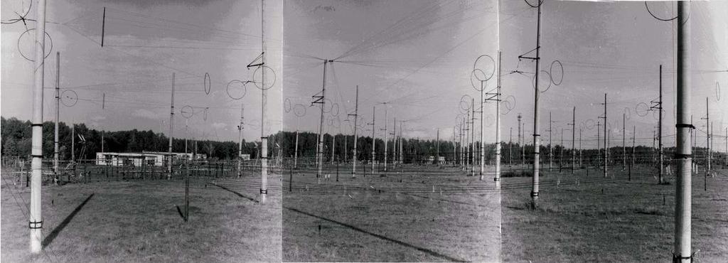
20 2.6 OTHR France - Nostradamus (area of Paris) Antenna array: source: The Nostradamus radar system is a set of 288 bi-cone antenna elements distributed over the arms of a three-branch star, with a buried infrastructure to shelter the transmission and reception electronics. Nostradamus detects any aircraft flying 700 to 2000 kilometers away. Indeed, this new radar concept is based on very-low-frequency waves (6 to 30 MHz) that bounce off the ionosphere, which allows it to detect targets beyond the horizon. Whereas transhorizon radars usely require huge linear antenna networks to beam the signals, the special surface distribution of Nostradamus makes it possible to control the electronic beams both in azimuth (360 ) and elevation. source: Nostradamus disturbing 14 MHz-amateurband caused by technical problems. (Only few days ) Nostradamus is often operating below khz.
21 Nostradamus sweeprate measurement: The oscillogram shows 30 ms gaps between the sweeps., which means sweeps/sec. The length of 1 sweep is about 2 msec. soundfile:
 in 2004.")

22 2.7 OTHR Iran Ticking pulses (like an old tin clock) on and khz (synchronuous) in Perhaps the Iranian military took its first steps to create an own OTHR. Sonagram by Gram50 Another version from Sonagram by Gram50. soundfile:
23 2.8 OTHR Israel Long lasting carriers were often observed around khz. The Israeli Navy seemed to test special reflections from carriers phase diagnostics??? Israeli OTHR with 50 sweeps/sec about 10 khz spread. Mysterious sawtooth generator on khz long lasting signals transmitted from Israel. A new kind of OTHR???

24 2.9 OTHR Romania on 3250 khz Coastal region of Romania (also active: Greek coastal region) Covering about 25 khz permanent active. Sweeprate measurement by Wavecom oscillogram: 1000 : 64 = sweeps/sec
25 2.10 OTHR Russia ABM2-Radar (Steelyard) on 14 MHz, 10 khz wide, operated with 10, 50 and 100 sweeps/sec. Continuous transmission! Very common in earlier years. Later burst version operating with 50 sweeps/sec, 10 khz wide in January Often on the 14 MHz Amateur band.

26 2.11 OTHR Turkey The Turkish OTH Radars are using the same parameters as the Cyprus Radar, 50 and 25 sweeps/sec and 20 khz spread. Their locations are Ankara and South-East and West-Turkey. The systems are often disturbing the 21 and 28 MHz-bands. Turkish OTH-Radar on khz with 50 sweeps/sec and 20 khz spread. Turkish OTH Radar with 50 sweeps/sec, 20 khz spread on 21 MHz. Fading is visible as dark layers. soundfile:

27 2.12 OTHR UK Rather new on shortwave, the British OTH Radar from the eastcoast of Britain. British OTH Radar on khz operating with 20 sweeps/sec, 20 khz spread. British OTH Radar with 20 sweeps/sec, 20 khz wide.

28 2.13 OTHR Ukraine The OTH Radar from Ukraine has been found per accident in January OTH Radar Ukraine on khz with 34.5 sweeps/sec and 10 khz spread. OTH Radar Ukraine on khz with 34.5 sweeps/sec and 10 khz spread.
, is a design concept for radar systems to allow them to detect targets at very long")

29 2.14 OTHR USA US Navy OTH Radar - source: Over-the-horizon radar, or OTH (sometimes also beyond the horizon, or BTH), is a design concept for radar systems to allow them to detect targets at very long ranges, typically up to thousands of kilometers. Several OTH radar systems were deployed starting in the 1950s and 60s as part of early warning radar systems, but these have generally been replaced by airborne early warning systems instead. OTH radars have recently been making something of a comeback, as the need for accurate long-range tracking becomes less important with the ending of the Cold War, and less-expensive ground based radars are once again being looked at for roles such as maritime reconnaissance and drug enforcement.
30 2.15 OTHR unknown Unknown Radar on khz in May burstsystem Sonagram on khz - duration of 1 burst = 4 sec Sweeprate measurement on khz, 16.1 sweeps/sec. soundfile:

31 3. Ocean Wave Radars 3.1 Codar (CODAR = COastal radar) Codar Info Site: Codar system from Italy disturbing the 24 MHz-Amateurband in May Observe the 100 khz spread! 2 sweeps/sec A typical Codar sonagram on 24 MHz, 2 sweeps/sec, short range version. Each sweep is divided in several blocks. soundfile:


32 Codar in Croatia (RTZub) with Goundplane Antenna not active in 2011 Codar in Croatia (Savudrije) not active in 2011 source:


33 Codar HF Radar on 24 MHz from Italy on the waterfall. Codar long range version with 1 sweep/sec below 5 MHz.

34 Far East Coastal Radar: Coastal Radar from China??? disturbing 7 MHz with 2.6 sweeps/sec Coastal Radar from China??? on khz 2.6 sweeps/sec disturbing khz (August - November 2011)
 WERA Info Site:")

35 3.2 WERA Germany (Ground Wave Radar University of Hamburg) WERA Info Site: The function of WERA: Shore based system:
36 WERA version used in north-west France on khz and below. French WERA version with 3.85 sweeps/sec. - END -
Dartmouth College SuperDARN Radars
 Dartmouth College SuperDARN Radars Under the guidance of Thayer School professor Simon Shepherd, a pair of backscatter radars were constructed in the desert of central Oregon over the Summer and Fall of
The EISCAT Heating Facility
 The EISCAT Heating Facility Michael Rietveld EISCAT Tromsø, Norway EISCAT radar school, 30 Aug-4 Sept, 2010, Sodankylä 1 Outline Description of the hardware Antenna beams Practical details- power levels
RADAR DEVELOPMENT BASIC CONCEPT OF RADAR WAS DEMONSTRATED BY HEINRICH. HERTZ VERIFIED THE MAXWELL RADAR.
 1 RADAR WHAT IS RADAR? RADAR (RADIO DETECTION AND RANGING) IS A WAY TO DETECT AND STUDY FAR OFF TARGETS BY TRANSMITTING A RADIO PULSE IN THE DIRECTION OF THE TARGET AND OBSERVING THE REFLECTION OF THE
Radar Reprinted from "Waves in Motion", McGourty and Rideout, RET 2005
 Radar Reprinted from "Waves in Motion", McGourty and Rideout, RET 2005 What is Radar? RADAR (Radio Detection And Ranging) is a way to detect and study far off targets by transmitting a radio pulse in the
AGF-216. The Earth s Ionosphere & Radars on Svalbard
 AGF-216 The Earth s Ionosphere & Radars on Svalbard Katie Herlingshaw 07/02/2018 1 Overview Radar basics what, how, where, why? How do we use radars on Svalbard? What is EISCAT and what does it measure?
A Bistatic HF Radar for Current Mapping and Robust Ship Tracking
 A Bistatic HF Radar for Current Mapping and Robust Ship Tracking Dennis Trizna Imaging Science Research, Inc. V. 703-801-1417 dennis @ isr-sensing.com www.isr-sensing.com Objective: Develop methods for
EISCAT Experiments. Anders Tjulin EISCAT Scientific Association 2nd March 2017
 EISCAT Experiments Anders Tjulin EISCAT Scientific Association 2nd March 2017 Contents 1 Introduction 3 2 Overview 3 2.1 The radar systems.......................... 3 2.2 Antenna scan patterns........................
Sw earth Dw Direct wave GRw Ground reflected wave Sw Surface wave
 WAVE PROPAGATION By Marcel H. De Canck, ON5AU Electromagnetic radio waves can propagate in three different ways between the transmitter and the receiver. 1- Ground waves 2- Troposphere waves 3- Sky waves
EISCAT_3D The next generation European Incoherent Scatter radar system Introduction and Brief Background
 EISCAT_3D The next generation European Incoherent Scatter radar system Introduction and Brief Background The high latitude environment is of increasing importance, not only for purely scientific studies,
Radar observables: Target range Target angles (azimuth & elevation) Target size (radar cross section) Target speed (Doppler) Target features (imaging)
 Target size (radar cross section) Target speed (Doppler) Target features (imaging)") Fundamentals of Radar Prof. N.V.S.N. Sarma Outline 1. Definition and Principles of radar 2. Radar Frequencies 3. Radar Types and Applications 4. Radar Operation 5. Radar modes What What is is Radar? Radar?
Fundamentals of Radar Prof. N.V.S.N. Sarma Outline 1. Definition and Principles of radar 2. Radar Frequencies 3. Radar Types and Applications 4. Radar Operation 5. Radar modes What What is is Radar? Radar?
VHF Propagation Overview 5-Oct-2016
 VHF Propagation Overview 5-Oct-2016 G0RVM 1 VHF Propagation Where in the radio spectrum is VHF? 30MHz to 300MHz for radio amateurs its 50MHz, 70MHz & 144MHz or 6m, 4m & 2m Name some types of VHF propagation?
6/20/2012 ACORN ACORN ACORN ACORN ACORN ACORN. Arnstein Prytz. Australian Coastal Ocean Radar Network (ACORN)
") The Australian Coastal Ocean Radar Network WERA Processing and Quality Control Arnstein Prytz Australian Coastal Ocean Radar Network Marine Geophysical Laboratory School of Earth and Environmental Sciences
The Australian Coastal Ocean Radar Network WERA Processing and Quality Control Arnstein Prytz Australian Coastal Ocean Radar Network Marine Geophysical Laboratory School of Earth and Environmental Sciences
4/18/2012. Supplement T3. 3 Exam Questions, 3 Groups. Amateur Radio Technician Class
 Amateur Radio Technician Class Element 2 Course Presentation ti ELEMENT 2 SUB-ELEMENTS Technician Licensing Class Supplement T3 Radio Wave Characteristics 3 Exam Questions, 3 Groups T1 - FCC Rules, descriptions
Scalable Ionospheric Analyser SIA 24/6
 Scalable Ionospheric Analyser SIA 24/6 Technical Overview Functional description The ATRAD Scalable Ionospheric Analyser SIA24/6 is designed to observe ionospheric irregularities and their drift in the
A bluffer s guide to Radar
 A bluffer s guide to Radar Andy French December 2009 We may produce at will, from a sending station, an electrical effect in any particular region of the globe; (with which) we may determine the relative
Rec. ITU-R P RECOMMENDATION ITU-R P *
 Rec. ITU-R P.682-1 1 RECOMMENDATION ITU-R P.682-1 * PROPAGATION DATA REQUIRED FOR THE DESIGN OF EARTH-SPACE AERONAUTICAL MOBILE TELECOMMUNICATION SYSTEMS (Question ITU-R 207/3) Rec. 682-1 (1990-1992) The
Section 1 Wireless Transmission
 Part : Wireless Communication! section : Wireless Transmission! Section : Digital modulation! Section : Multiplexing/Medium Access Control (MAC) Section Wireless Transmission Intro. to Wireless Transmission
Chapter 6 Propagation
 Chapter 6 Propagation Al Penney VO1NO Objectives To become familiar with: Classification of waves wrt propagation; Factors that affect radio wave propagation; and Propagation characteristics of Amateur
2.9 Internet-controlled Software-Defined Radios (Web-SDR)
") 28 KLINGENFUSS.ORG 2017/2018 GUIDE TO UTILITY RADIO STATIONS 2.9 Internet-controlled Software-Defined Radios (Web-SDR) In urban areas all over the world, shortwave radio listeners experience an increasing
28 KLINGENFUSS.ORG 2017/2018 GUIDE TO UTILITY RADIO STATIONS 2.9 Internet-controlled Software-Defined Radios (Web-SDR) In urban areas all over the world, shortwave radio listeners experience an increasing
Modern radio techniques
 Modern radio techniques for probing the ionosphere Receiver, radar, advanced ionospheric sounder, and related techniques Cesidio Bianchi INGV - Roma Italy Ionospheric properties related to radio waves
FMCW waveform generator requirements for ionospheric
 Radio Science, Volume 33 Number 4, Pages 1069-1076, July-August, 1998 FMCW waveform generator requirements for ionospheric over-the-horizon G. F: Earl radar Electronics and Surveillance Research Laboratory,
Chapter 1: Telecommunication Fundamentals
 Chapter 1: Telecommunication Fundamentals Block Diagram of a communication system Noise n(t) m(t) Information (base-band signal) Signal Processing Carrier Circuits s(t) Transmission Medium r(t) Signal
 Page 1 of 8 Search Contact NRL Personnel Locator Human Resources Public Affairs Office Visitor Info Planning a Visit Directions Maps Weather & Traffic Field Sites Stennis Monterey VXS-1 Chesapeake Bay
Ionospheric Propagation
 Ionospheric Nick Massey VA7NRM 1 Electromagnetic Spectrum Radio Waves are a form of Electromagnetic Radiation Visible Light is also a form of Electromagnetic Radiation Radio Waves behave a lot like light
Solar Radar Experiments
 Solar Radar Experiments Paul Rodriguez Plasma Physics Division Naval Research Laboratory Washington, DC 20375 phone: (202) 767-3329 fax: (202) 767-3553 e-mail: paul.rodriguez@nrl.navy.mil Award # N0001498WX30228
The Precision Expandable Radar Calibration Sphere (PERCS) With Applications for Laser Imaging and Ranging
 With Applications for Laser Imaging and Ranging") The Precision Expandable Radar Calibration Sphere (PERCS) With Applications for Laser Imaging and Ranging Paul A. Bernhardt 1, Andy Nicholas 2, Linda Thomas 3, Mark Davis 3 1 Plasma Physics Division, 2
The Precision Expandable Radar Calibration Sphere (PERCS) With Applications for Laser Imaging and Ranging Paul A. Bernhardt 1, Andy Nicholas 2, Linda Thomas 3, Mark Davis 3 1 Plasma Physics Division, 2
Coastal Surveillance: Complex system of X-band and High Frequency Surface Wave Radars
 Coastal Surveillance: Complex system of X-band and High Frequency Surface Wave Radars N. Colin (1), G. Auffray (2) (1)Thales Air Systems, Surface Radar Hameau de Roussigny 91470 Limours, France nathalie.colin@thalesgroup.com
4/29/2012. General Class Element 3 Course Presentation. Radio Wave Propagation. Radio Wave Propagation. Radio Wave Propagation.
 General Class Element 3 Course Presentation ti ELEMENT 3 SUB ELEMENTS General Licensing Class Subelement G3 3 Exam Questions, 3 Groups G1 Commission s Rules G2 Operating Procedures G3 G4 Amateur Radio
Characteristics of HF Coastal Radars
 Function Characteristics System 1 Maximum operational (measurement) range** Characteristics of HF Coastal Radars 5 MHz Long-range oceanographic 160-220 km average during (daytime)* System 2 System 3 System
Aa-Qoq~4«2l bsto-ftfc-oo&l
 Aa-Qoq~4«2l bsto-ftfc-oo&l Round-The-World High Frequency Propagation: A Synoptic Study Mark A. Tyler 19960429 024 APPROVED FOR PUBLIC RELEASE Commonwealth of Australia DTIC QUALITY INSPECTED 1 DEPARTMENT.OF
RADIO WAVE PROPAGATION
 CHAPTER 2 RADIO WAVE PROPAGATION Radio direction finding (RDF) deals with the direction of arrival of radio waves. Therefore, it is necessary to understand the basic principles involved in the propagation
UNIT Derive the fundamental equation for free space propagation?
 UNIT 8 1. Derive the fundamental equation for free space propagation? Fundamental Equation for Free Space Propagation Consider the transmitter power (P t ) radiated uniformly in all the directions (isotropic),
Reading 28 PROPAGATION THE IONOSPHERE
 Reading 28 Ron Bertrand VK2DQ http://www.radioelectronicschool.com PROPAGATION THE IONOSPHERE The ionosphere is a region of the upper atmosphere extending from a height of about 60 km to greater than 500
Radar astronomy and radioastronomy using the over-the-horizon radar NOSTRADAMUS. ONERA, Département Electromagnétisme et Radar
 Radar astronomy and radioastronomy using the over-the-horizon radar NOSTRADAMUS J-F. Degurse 1,2, J-Ph. Molinié 1, V. Rannou 1,S. Marcos 2 1 ONERA, Département Electromagnétisme et Radar 2 L2S Supéléc,
RECOMMENDATION ITU-R S.1340 *,**
 Rec. ITU-R S.1340 1 RECOMMENDATION ITU-R S.1340 *,** Sharing between feeder links the mobile-satellite service and the aeronautical radionavigation service in the Earth-to-space direction in the band 15.4-15.7
Measurements of doppler shifts during recent auroral backscatter events.
 Measurements of doppler shifts during recent auroral backscatter events. Graham Kimbell, G3TCT, 13 June 2003 Many amateurs have noticed that signals reflected from an aurora are doppler-shifted, and that
RECOMMENDATION ITU-R S.1341*
 Rec. ITU-R S.1341 1 RECOMMENDATION ITU-R S.1341* SHARING BETWEEN FEEDER LINKS FOR THE MOBILE-SATELLITE SERVICE AND THE AERONAUTICAL RADIONAVIGATION SERVICE IN THE SPACE-TO-EARTH DIRECTION IN THE BAND 15.4-15.7
Ionospheric effect of HF surface wave over-the-horizon radar
 RADIO SCIENCE, VOL. 41,, doi:10.1029/2005rs003323, 2006 Ionospheric effect of HF surface wave over-the-horizon radar Huotao Gao, 1 Geyang Li, 1 Yongxu Li, 1 Zijie Yang, 1 and Xiongbin Wu 1 Received 25
MAN MADE RADIO EMISSIONS RECORDED BY CASSINI/RPWS DURING EARTH FLYBY
 MAN MADE RADIO EMISSIONS RECORDED BY CASSINI/RPWS DURING EARTH FLYBY G. Fischer and H. O. Rucker Abstract In the days around closest approach of the Cassini spacecraft to Earth at August 18, 1999, the
OBJECTIVES: PROPAGATION INTRO RADIO WAVES POLARIZATION LINE OF SIGHT, GROUND WAVE, SKY WAVE IONOSPHERE REGIONS PROPAGATION, HOPS, SKIPS ZONES THE
 WAVE PROPAGATION OBJECTIVES: PROPAGATION INTRO RADIO WAVES POLARIZATION LINE OF SIGHT, GROUND WAVE, SKY WAVE IONOSPHERE REGIONS PROPAGATION, HOPS, SKIPS ZONES THE IONOSPHERIC LAYERS ABSORPTION AND FADING
C three decadesz'other reviews serve that purpose (e.g., Barrick, 1978;
 STATUS OF HF RADARS FOR WAVE-HEIGHT DIRECTIONAL SPECTRAL MEASUREMENTS - Donald E. Barrick 1 Introduction SThis manuscript is a concise review of the status of high-frequency (HF) radars for measuring various
RECOMMENDATION ITU-R SA (Question ITU-R 210/7)
") Rec. ITU-R SA.1016 1 RECOMMENDATION ITU-R SA.1016 SHARING CONSIDERATIONS RELATING TO DEEP-SPACE RESEARCH (Question ITU-R 210/7) Rec. ITU-R SA.1016 (1994) The ITU Radiocommunication Assembly, considering
Rec. ITU-R SA.1016 1 RECOMMENDATION ITU-R SA.1016 SHARING CONSIDERATIONS RELATING TO DEEP-SPACE RESEARCH (Question ITU-R 210/7) Rec. ITU-R SA.1016 (1994) The ITU Radiocommunication Assembly, considering
Interpretation and Classification of P-Series Recommendations in ITU-R
 Int. J. Communications, Network and System Sciences, 2016, 9, 117-125 Published Online May 2016 in SciRes. http://www.scirp.org/journal/ijcns http://dx.doi.org/10.4236/ijcns.2016.95010 Interpretation and
Monitoring the polar cap/ auroral ionosphere: Industrial applications. P. T. Jayachandran Physics Department University of New Brunswick Fredericton
 Monitoring the polar cap/ auroral ionosphere: Industrial applications P. T. Jayachandran Physics Department University of New Brunswick Fredericton Outline Ionosphere and its effects on modern and old
Technician License Course Chapter 4
 Technician License Course Chapter 4 Propagation, Basic Antennas, Feed lines & SWR K0NK 26 Jan 18 The Antenna System Antenna: Facilitates the sending of your signal to some distant station. Feed line: Connects
Digital Sounder: HF Diagnostics Module:Ionosonde Dual Channel ( ) Eight Channel ( )
 Eight Channel ( )") CENTER FOR REMOTE SE NSING, INC. Digital Sounder: HF Diagnostics Module:Ionosonde Dual Channel (001-2000) Eight Channel (004-2006) 2010 Center for Remote Sensing, Inc. All specifications subject to change
CENTER FOR REMOTE SE NSING, INC. Digital Sounder: HF Diagnostics Module:Ionosonde Dual Channel (001-2000) Eight Channel (004-2006) 2010 Center for Remote Sensing, Inc. All specifications subject to change
Hermanus Magnetic Observatory (HMO)
") Hermanus Magnetic Observatory (HMO) As a Space Physics facility in Africa Presented by Danie Gouws & Elda Saunderson The HMO in a nutshell... The Hermanus Magnetic Observatory (HMO) is a national facility
Hermanus Magnetic Observatory (HMO) As a Space Physics facility in Africa Presented by Danie Gouws & Elda Saunderson The HMO in a nutshell... The Hermanus Magnetic Observatory (HMO) is a national facility
APPLICATION OF OCEAN RADAR ON THE BALTIC, FEATURES AND LIMITATIONS
 APPLICATION OF OCEAN RADAR ON THE BALTIC, FEATURES AND LIMITATIONS Thomas Helzel, Matthias Kniephoff, Leif Petersen, Markus Valentin Helzel Messtechnik GmbH e-mail: helzel@helzel.com Presentation at Hydro
2.9 Internet-controlled Software-Defined Radios (Web-SDR)
") Monitoring utility stations 31 2.9 Internet-controlled Software-Defined Radios (Web-SDR) In urban areas all over the world, shortwave radio listeners experience an increasing level of man-made noise by
Monitoring utility stations 31 2.9 Internet-controlled Software-Defined Radios (Web-SDR) In urban areas all over the world, shortwave radio listeners experience an increasing level of man-made noise by
Radar. Seminar report. Submitted in partial fulfillment of the requirement for the award of degree Of Mechanical
 A Seminar report on Radar Submitted in partial fulfillment of the requirement for the award of degree Of Mechanical SUBMITTED TO: SUBMITTED BY: www.studymafia.org www.studymafia.org Preface I have made
CHAPTER 1 INTRODUCTION
 1 CHAPTER 1 INTRODUCTION In maritime surveillance, radar echoes which clutter the radar and challenge small target detection. Clutter is unwanted echoes that can make target detection of wanted targets
Antennas and Propagation
 Antennas and Propagation Chapter 5 Introduction An antenna is an electrical conductor or system of conductors Transmission - radiates electromagnetic energy into space Reception - collects electromagnetic
4/29/2012. General Class Element 3 Course Presentation. Ant Antennas as. Subelement G9. 4 Exam Questions, 4 Groups
 General Class Element 3 Course Presentation ti ELEMENT 3 SUB ELEMENTS General Licensing Class Subelement G9 Antennas and Feedlines 4 Exam Questions, 4 Groups G1 Commission s Rules G2 Operating Procedures
Lecture 1 INTRODUCTION. Dr. Aamer Iqbal Bhatti. Radar Signal Processing 1. Dr. Aamer Iqbal Bhatti
 Lecture 1 INTRODUCTION 1 Radar Introduction. A brief history. Simplified Radar Block Diagram. Two basic Radar Types. Radar Wave Modulation. 2 RADAR The term radar is an acronym for the phrase RAdio Detection
RECOMMENDATION ITU-R SA.1624 *
 Rec. ITU-R SA.1624 1 RECOMMENDATION ITU-R SA.1624 * Sharing between the Earth exploration-satellite (passive) and airborne altimeters in the aeronautical radionavigation service in the band 4 200-4 400
Centralised Services 7-2 Network Infrastructure Performance Monitoring and Analysis Service
 EUROCONTROL Centralised Services 7-2 Network Infrastructure Performance Monitoring and Analysis Service Monitoring the performance of 1030/1090 MHz RF bands A COST-EFFICIENT SOLUTION To make best use of
Aircraft Scatter Propagation on 10 GHz using JT65C
 Aircraft Scatter Propagation on 10 GHz using JT65C Results of initial Tests over a 624 km Path By Rex Moncur VK7MO and David Smith VK3HZ This is an initial report of our first tests of 10 GHz propagation
ATS 351 Lecture 9 Radar
 ATS 351 Lecture 9 Radar Radio Waves Electromagnetic Waves Consist of an electric field and a magnetic field Polarization: describes the orientation of the electric field. 1 Remote Sensing Passive vs Active
An Accurate phase calibration Technique for digital beamforming in the multi-transceiver TIGER-3 HF radar system
 An Accurate phase calibration Technique for digital beamforming in the multi-transceiver TIGER-3 HF radar system H. Nguyen, J. Whittington, J. C Devlin, V. Vu and, E. Custovic. Department of Electronic
Antennas and Propagation Chapters T4, G7, G8 Antenna Fundamentals, More Antenna Types, Feed lines and Measurements, Propagation
 Antennas and Propagation Chapters T4, G7, G8 Antenna Fundamentals, More Antenna Types, Feed lines and Measurements, Propagation =============================================================== Antenna Fundamentals
Introduction to: Radio Navigational Aids
 Introduction to: Radio Navigational Aids 1 Lecture Topics Basic Principles Radio Directional Finding (RDF) Radio Beacons Distance Measuring Equipment (DME) Instrument Landing System (ILS) Microwave Landing
RADAR CHAPTER 3 RADAR
 RADAR CHAPTER 3 RADAR RDF becomes Radar 1. As World War II approached, scientists and the military were keen to find a method of detecting aircraft outside the normal range of eyes and ears. They found
CODAR. Ben Kravitz September 29, 2009
 CODAR Ben Kravitz September 29, 2009 Outline What is CODAR? Doppler shift Bragg scatter How CODAR works What CODAR can tell us What is CODAR? Coastal Ocean Dynamics Application Radar Land-based HF radar
3C5 Telecommunications. what do radios look like? mobile phones. Linda Doyle CTVR The Telecommunications Research Centre
 3C5 Telecommunications what do radios look like? Linda Doyle CTVR The Telecommunications Research Centre ledoyle@tcd.ie Oriel/Dunlop House 2009 mobile phones talk is cheap.. bluetooth 3G WLAN/802.11 GSM
RADIO WAVES PROPAGATION
 RADIO WAVES PROPAGATION Definition Radio waves propagation is a term used to explain how radio waves behave when they are transmitted, or are propagated from one point on the Earth to another. Radio Waves
Ground based measurements of ionospheric turbulence manifestations induced by the VLF transmitter ABSTRACT
 Ground based measurements of ionospheric turbulence manifestations induced by the VLF transmitter Dmitry S. Kotik, 1 Fedor I. Vybornov, 1 Alexander V. Ryabov, 1 Alexander V. Pershin 1 and Vladimir A. Yashnov
Antennas and Propagation. Chapter 5
 Antennas and Propagation Chapter 5 Introduction An antenna is an electrical conductor or system of conductors Transmission - radiates electromagnetic energy into space Reception - collects electromagnetic
Radio Communication. Presentation created by: András Balogh
 Radio Communication Presentation created by: András Balogh AM and FM The goal is to transmit a modulating signal S(t) via a wave sin(ωt). In case of AM, the product of the modulation is f(t)=(a+s(t))*sin(ωt);
Antennas and Propagation. Chapter 5
 Antennas and Propagation Chapter 5 Introduction An antenna is an electrical conductor or system of conductors Transmission - radiates electromagnetic energy into space Reception - collects electromagnetic
A Bistatic HF Radar for Current Mapping and Robust Ship Tracking
 A Bistatic HF Radar for Current Mapping and Robust Ship Tracking D. B. Trizna Imaging Science Research, Inc. 6103B Virgo Court Burke, VA, 22015 USA Abstract- A bistatic HF radar has been developed for
Amateur Radio License. Propagation and Antennas
 Amateur Radio License Propagation and Antennas Todays Topics Propagation Antennas Propagation Modes Ground wave Low HF and below, ground acts as waveguide Line-of-Sight (LOS) VHF and above, radio waves
Antennas and Propagation. Prelude to Chapter 4 Propagation
 Antennas and Propagation Prelude to Chapter 4 Propagation Introduction An antenna is an electrical conductor or system of conductors for: Transmission - radiates electromagnetic energy into space (involves
Daily and seasonal variations of TID parameters over the Antarctic Peninsula
 Daily and seasonal variations of TID parameters over the Antarctic Peninsula A. Zalizovski 1, Y. Yampolski 1, V. Paznukhov 2, E. Mishin 3, A. Sopin 1 1. Institute of Radio Astronomy, National Academy of
Antenna Engineering Lecture 0: Introduction
 Antenna Engineering Lecture 0: Introduction ELC 405a Fall 2011 Department of Electronics and Communications Engineering Faculty of Engineering Cairo University 2 Outline 1 Why Study Antenna Engineering?
DRM+ The Efficient Solution for Digitising FM
 DRM+ The Efficient Solution for Digitising FM ABU Digital Broadcasting Symposium 2009 A. Waal Kuala Lumpur 10.03.2009 Contents What is DRM+? DRM+ system overview Bandwidth Data rate Service information
RF noise and interference within the ITU bands the ACORN experience
 RF noise and interference within the ITU bands the ACORN experience Simone Cosoli School of Civil, Environmental and Mining Engineering The UWA Oceans Institute The University of Western Australia Outline
Oil Spill Detection (OSD) by using X-band radar
 by using X-band radar") Oil Spill Detection (OSD) by using X-band radar Ina Adegeest, Rutter Inc./ OceanWaveS GmbH, Germany Head Office: Rutter Inc. Canadian company Head Office in St. John s, NL, Canada Incorporated in 1998
Oil Spill Detection (OSD) by using X-band radar Ina Adegeest, Rutter Inc./ OceanWaveS GmbH, Germany Head Office: Rutter Inc. Canadian company Head Office in St. John s, NL, Canada Incorporated in 1998
Microwave Remote Sensing
 Provide copy on a CD of the UCAR multi-media tutorial to all in class. Assign Ch-7 and Ch-9 (for two weeks) as reading material for this class. HW#4 (Due in two weeks) Problems 1,2,3 and 4 (Chapter 7)
High Resolution W-Band Radar Detection and Characterization of Aircraft Wake Vortices in Precipitation. Thomas A. Seliga and James B.
 High Resolution W-Band Radar Detection and Characterization of Aircraft Wake Vortices in Precipitation Thomas A. Seliga and James B. Mead 4L 4R 4L/22R 4R/22L W-Band Radar Site The W-Band Radar System
COMPATIBILITY STUDY BETWEEN RADIO NAVIGATION SATELLITE SERVICE IN THE MHz BAND AND FIXED SERVICE OPERATING UNDER RR S5.355 AND S5.
 SE-28, Paris 06 07 July 1998 SE-28(98) Doc103-Rev1 COMPATIBILITY STUDY BETWEEN RADIO NAVIGATION SATELLITE SERVICE IN THE 1559-1610 MHz BAND AND FIXED SERVICE OPERATING UNDER RR S5.355 AND S5.359 Presented
Radar System Impacts on Spectrum Management
 Radar System Impacts on Spectrum Management National Spectrum Management Association Mitchell Lazarus 703-812-0440 0440 lazarus@fhhlaw.com May 13, 2014 Radar: Basic Principle Radio signal reflects from
AN INTRODUCTION TO VHF/ UHF PROPAGATION. Paul Wilton, M1CNK
 AN INTRODUCTION TO VHF/ UHF PROPAGATION Paul Wilton, M1CNK OVERVIEW Introduction Propagation Basics Propagation Modes Getting Started in 2m DX INTRODUCTION QRV on 2m SSB since Aug 1998, on 6m since Jan
Concerns with Sharing Studies for HF Oceanographic Radar Frequency Allocation Request (WRC-12 Agenda Item 1.15, Document 5B/417)
") Naval Research Laboratory Washington, DC 20375-5320 NRL/MR/5320--10-9288 Concerns with Sharing Studies for HF Oceanographic Radar Frequency Allocation Request (WRC-12 Agenda Item 1.15, Document 5B/417)
Naval Research Laboratory Washington, DC 20375-5320 NRL/MR/5320--10-9288 Concerns with Sharing Studies for HF Oceanographic Radar Frequency Allocation Request (WRC-12 Agenda Item 1.15, Document 5B/417)
3000 Series Granger Broadband HF Multi-Mode SPIRA-CONE Antennas
 3000 Series Granger Broadband HF Multi-Mode SPIRA-CONE Antennas 2 to 30 MHz Frequency Range, Dependent Upon Up to KW Average, 40 KW Peak Power Rating Horizontal-Elliptical to Reduce Fading Log-Periodic
RECOMMENDATION ITU-R BS.80-3 * Transmitting antennas in HF broadcasting
 Rec. ITU-R BS.80-3 1 RECOMMENDATION ITU-R BS.80-3 * Transmitting antennas in HF broadcasting (1951-1978-1986-1990) The ITU Radiocommunication Assembly, considering a) that a directional transmitting antenna
Technical and operational characteristics of oceanographic radars operating in sub-bands within the frequency range 3-50 MHz
 Recommendation ITU-R M.1874-1 (02/2013) Technical and operational characteristics of oceanographic radars operating in sub-bands within the frequency range 3-50 MHz M Series Mobile, radiodetermination,
Introduction to HF Propagation. Rick Fletcher, W7YP FVARC November 20, 2018
 Introduction to HF Propagation Rick Fletcher, W7YP FVARC November 20, 2018 Topics The HF Bands How HF propagation works Overview by HF band Sources of solar and propagation information Working HF during
Propagation: From Them to Us
 Propagation: From Them to Us (c) 2016 Nils Schiffhauer, DK8OK Utility DXing is like observing other people at work. Their work is to establish communications between two stations or within a network, or
RECOMMENDATION ITU-R F.1819
 Rec. ITU-R F.1819 1 RECOMMENDATION ITU-R F.1819 Protection of the radio astronomy service in the 48.94-49.04 GHz band from unwanted emissions from HAPS in the 47.2-47.5 GHz and 47.9-48.2 GHz bands * (2007)
Some Notes on STANAG A DXer s View
 Some Notes on STANAG 4285 - A DXer s View STANAG 4285 is a single-tone modem, agreed upon by NATO member states in the 1980 s. The unclassified specification can be downloaded here. Until today, there
CHAPTER ONE INTRODUCTION
 CHAPTER ONE INTRODUCTION 1.1 Background A communication system transmits information from one place to another, whether separated by a few kilometers or by transoceanic distances. Information is often
HF RADIO PROPAGATION AT HIGH LATITUDES: OBSERVATIONS AND PREDICTIONS FOR QUIET AND DISTURBED CONDITIONS
 HF RADIO PROPAGATION AT HIGH LATITUDES: OBSERVATIONS AND PREDICTIONS FOR QUIET AND DISTURBED CONDITIONS Bjorn Jacobsen and Vivianne Jodalen Norwegian Defence Research Establishment (FFI) P.O. Box 25, N-2027
HF RADAR DETECTS AN APPROACHING TSUNAMI WAVE ALREADY IN DEEP WATERS
 HF RADAR HF RADAR DETECTS AN APPROACHING TSUNAMI WAVE ALREADY IN DEEP WATERS Long-Lih Huang 1, Anna Dzvonkovskaya 2, Mal Heron 3 1 All-Star-Technology Co., Taipei, Taiwan 2 Helzel Messtechnik GmbH, Kaltenkirchen,
EE Chapter 14 Communication and Navigation Systems
 EE 2145230 Chapter 14 Communication and Navigation Systems Two way radio communication with air traffic controllers and tower operators is necessary. Aviation electronics or avionics: Avionic systems cover
The Largest Ionospheric Disturbances Produced by the HAARP HF Facility
 The Largest Ionospheric Disturbances Produced by the HAARP HF Facility Paul A. Bernhardt 1, Carl L. Seifring 1, Stanley J. Briczinski 2, Elizabeth A. kendall 3, Brenton J. Watkins 4, William Bristow 4,
1. Terrestrial propagation
 Rec. ITU-R P.844-1 1 RECOMMENDATION ITU-R P.844-1 * IONOSPHERIC FACTORS AFFECTING FREQUENCY SHARING IN THE VHF AND UHF BANDS (30 MHz-3 GHz) (Question ITU-R 218/3) (1992-1994) Rec. ITU-R PI.844-1 The ITU
Keywords. DECCA, OMEGA, VOR, INS, Integrated systems
 Keywords. DECCA, OMEGA, VOR, INS, Integrated systems 7.4 DECCA Decca is also a position-fixing hyperbolic navigation system which uses continuous waves and phase measurements to determine hyperbolic lines-of
First Results from the 2014 Coordinated Measurements Campaign with HAARP and CASSIOPE/ePOP
 First Results from the 2014 Coordinated Measurements Campaign with HAARP and CASSIOPE/ePOP Carl L. Siefring, Paul A. Bernhardt, Stanley J. Briczinski, and Michael McCarrick Naval Research Laboratory Matthew
Antennas & Propagation. CSG 250 Fall 2007 Rajmohan Rajaraman
 Antennas & Propagation CSG 250 Fall 2007 Rajmohan Rajaraman Introduction An antenna is an electrical conductor or system of conductors o Transmission - radiates electromagnetic energy into space o Reception
Topics in Propagation
 Topics in Propagation Extra Class Course Spring 2013 Andy Durbin k3wyc Propagation The magic that allows a signal to travel between the transmitting antenna and the receiving antenna. This course is limited