Dear Valued Customer,
|
|
|
- April Wheeler
- 6 years ago
- Views:
Transcription
1
2

3 Dear Valued Customer, Thank you for choosing Listen! All of us at Listen are dedicated to providing you with the highest quality products available. We take great pride in their outstanding performance because we care that you are completely satisfied. That s why we independently certify them to the highest quality standards and back them with a limited lifetime guarantee. We stand ready to answer any questions you might have during installation or in the operation of our products. Should you experience any problems whatsoever with your Listen products, we are ready to help you in any way we can with prompt, efficient customer care. Because at Listen, it s all about you! And should you have any comments on how we might improve our products or our service, we re here to listen. Here s how to reach us: North America fax support@listentech.com Thank you and enjoy your listening experience! Best regards, Russell Gentner and the Listen Team In the few instances where repairs were needed, 99% of all clients indicated that they were happy with repair turn-around-times and 85% of the time, clients were without their product for less than 10 days! Overall client satisfaction of working with Listen was rated 4.8 out of 5. Please continue with your excellent attitude toward customer satisfaction. You guys are great! I ve never had such good service from any company. Keep up the good work! You stand behind your product wonderfully. Assistive Listening Language Interpretation Soundfield Tour Group Conferencing
4
5 Value Package Table of Contents Design Guide FM Technology Overview 5 System Overview 6 Key Concepts in Value Package Setup 7 Alternative Options for Value Package Setup 11 Notes 13 LT Stationary FM Transmitter Specifications 20 Block Diagram 21 Quick Reference 22 Setup Instructions 23 Operating Instructions 25 Accessories 29 Notes 30 LR FM Receiver Specifications 36 Block Diagram 7 3 Quick Reference 38 Setup Instructions 39 Accessories 42 Notes 43 Supplementary Information Battery Charging Information 50 Frequency Chart 51 Troubleshooting 52 Frequently Asked Questions 54 Compliance, Warranty and Contact Information 55 Notes 57 Design Guide LT LR Supplementary
6

7
8
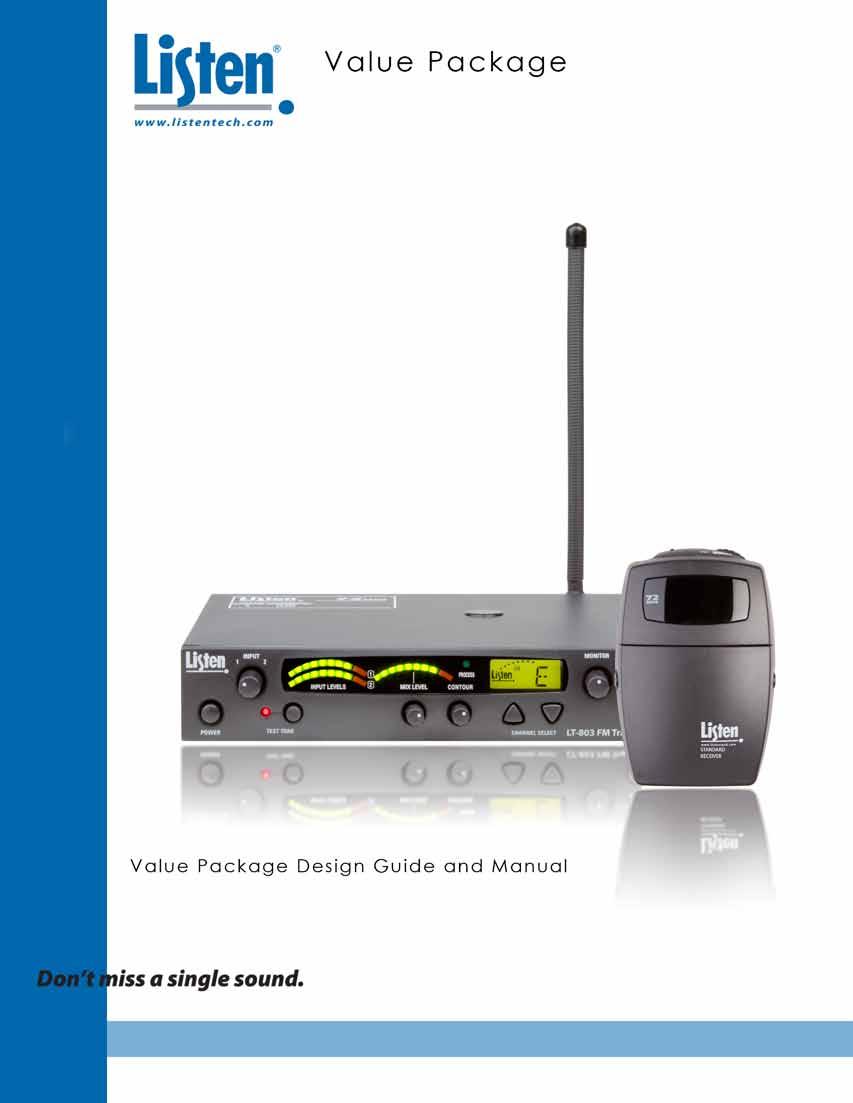
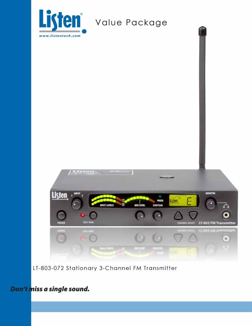
 LT-803-072 Stationary 3-Channel FM Transmitter (4) LR-200-072 Standard 3-Channel FM Receiver (1) LA-123 90 Helical Antenna (4) LA-161 Single Ear Bud (1) LA-304 Assistive")

9 Value Package Design Guide Table of Contents FM Technology Overview 5 System Overview 6 Key Concepts in Value Package Setup 7 Alternative Options for Value Package Setup 11 Notes 13 Design Guide Value Package Contents (1) LT Stationary 3-Channel FM Transmitter (4) LR Standard 3-Channel FM Receiver (1) LA Helical Antenna (4) LA-161 Single Ear Bud (1) LA-304 Assistive Listening Notification Signage Kit (1) LA VDC Power Supply (1) Installation Guide LA-161 Single Ear Bud 72 LT-803 STANDARD RECEIVER LT Stationary 3-Channel FM Transmitter LR Standard 3-Channel FM Receiver 12 VDC Power Supply LA Helical Antenna This facility is equipped with a hearing assistance system. Please ask for a receiver. LA-304 Assitive Listening Notification Signage Kit Installation Guide 3
10
11 Frequency Modulation (FM) Technology Overview Frequency modulation or (FM) is a means of transmitting audio using electromagnetic waves. This same technology is used by local FM radio stations to broadcast music. FM signals can travel through most barriers walls, floors, and ceilings. The distance a signal travels has many different variables such as Radio Frequency (RF) output power, the type and placement of the antenna, and the broadcasted frequency. Unlike infrared, FM transmission are not secure. This enables a receiver to travel further distances from the source. This section of the manual will help you design a system that will get the best range and least amount of interference. Design Guide Audio Mixer 72 STANDARD RECEIVER LT-803 FM Receiver FM Transmitter Audio Source 5
12 Design Guide System Overview There are four main components to the Value Package the transmitter, antenna, receiver and input source. Input Source The input source can be audio from a sound board, microphone or a personal audio source like a CD player, MP3 player, computer, DVD, etc. Audio will be connected into the audio inputs of the Stationary Transmitter. Transmitter The LT transmitter modulates the audio on an FM carrier and transmits the signal via an antenna. LT Stationary 3-Channel FM Transmitter (72 MHz) LT-803 Antenna The LP-3CV-072 includes the LA Helical Antenna. This antenna has a BNC connector and should be mounted on the back of the LT For further antenna options see page 11. Channel Select Alkaline Battery Select NiMH Channel Select Alkaline Battery Select NiMH Receivers LA Helical Antenna The LR receiver captures the signal sent from the transmitter and outputs it into the LA-161 Single ear bud. Listen offers a variety of receivers. 72 LR Standard 3-Channel FM Receiver (72 MHz) STANDARD RECEIVER 6
13 Key Concepts in Value Package Setup Input Selection The LT has two audio input options: Input 1 and Input 2. Input 1 is a balanced connection using either an XLR or ¼ in. phono connector, and input 2 is two unbalanced phono connectors. Use Input 1 if you are using a microphone or if you have a balanced connection such as a professional audio mixer (you can also use Input 1 for unbalanced connections). Use Input 2 to connect to an unbalanced audio source. Design Guide Balanced XLR or 1/4 in. phono connector Unbalanced right and left phono connectors Input 1: Connecting the audio source Input 1 offers a choice of balanced XLR or ¼ in. phono connector. Plug an audio source into Input 1: move the input select switch to the type of input source being used. Select Line for Line Inputs, Mic for dynamic microphones or Mic + PH Power for condenser microphones. A balanced feed from a soundboard can also be used with Input 1. Input 2: Connect the audio source Plug your unbalanced audio source into Input 2 and select the audio level switch for -10 dbu or +10 dbu to match the audio level coming from your equipment. 7
14 Design Guide Key Concepts in Value Package Setup Using Multiple inputs The LT can accommodate multiple inputs simultaneously with the use of the input level potentiometer. When multiple inputs are present, both input level lights will be activated. LT-803 Mix Level Input Level Knob The mix level acts as the master transmit control. It will increase the transmit gain on the mix of the two levels (if two levels are in use). LT-803 Mix Level Adjustment 8
15 Key Concepts in Value Package Setup Selecting Transmitting Frequencies Use this section of the guide to choose the channel settings for the transmitter and receivers. Design Guide Find transmission channel(s) The goal is to find a transmission channel(s) that is free from interference. Interference comes from transmitters and other outside FM signals. Listen s LT offers 3 different channels to choose from With 3 different channels to choose from, the chance of finding an interference free channel is increased. The best way to check for interference is to turn the LR on and listen to each channel. Transmit on the channel that has the least amount of noise. Testing System Monitor Jack The headphone jack is used to monitor the mix of input 1 & 2. You can adjust the monitor level with the volume knob. The headphone jack is a standard 3.5 mm jack. LT-803 Test Tone Use the test tone to transmit a 400 Hz tone. This tone will allow the end user to know if the system is transmitting properly. All receivers should be able to hear this tone if tuned to the proper channel. 3 Headphone Monitoring Jack LT-803 Test Tone Button 9
16 Design Guide Key Concepts in Value Package Setup Antenna placement (rear) Rear mounted antenna Rear mounting the LA Helical Antenna (72 MHz) will allow the transmitter to be moved if necessary. Maximizing Transmission Range For proper and dependable operation, Listen receivers need to receive a strong and consistent signal from the originating transmitter. The following strategies should be used to maximize this signal: Transmitting antenna When designing and installing your system, keep in mind that the location of both the transmitting and receiving antennas is critical to maximize broadcast range. Minimize the distance and remove any obstructions between the transmitting and receiving antennas. Keep transmitting and receiving antennas (receiver earphone cord) away from metal or conductive objects. RF Power switch Position the RF Power switch on the back of the LT to full RF Power, unless lower power is necessary. Low, med or high RF power 10
17 Alternative Options for Value Package Setup Remote antenna The LA-122 Universal Antenna Kit (72 and 216 MHz) and the LA-116 Coaxial Dipole Remote Antenna (72 MHz) connect to the LT and can be placed away from the transmitter for better range. They also allow the unit to be rack mounted with the antenna remotely using the LA-326 Universal Rack Mounting Kit. Both the LA-122 and LA-116 come with 25 of black coaxial cable (RG-58). Design Guide ATTENTION: Long cable runs can result in signal degradation due to the loss characteristics of the cable. Minimize cable runs as much as possible or use low loss RG-8 cable. LA-122 Universal Antenna Kit (72 and 216 MHz) LR Portable Digital FM Receiver (72 MHz) LR Portable Display FM Receiver (72 MHz) LR Portable Programmable Display FM Receiver (72 MHz) LR-100 Output Level Mute Squelch Up RF Power Channel Seek Speaker Power Headphone Down LR Stationary FM Receiver/ Power Amplifier (72 MHz) Antenna Output Speaker Battery 12VDC Ground Up Control Down Mute Common - LA-116 Coaxial Dipole Remote Antenna (72 MHz) Receiver Options Listen offers a variety of portable and stationary receivers. Each receiver offers different features to help further customize your FM system. ATTENTION: The SQ Super Quiet function must be turned OFF for better audio quality when using the LT contained in this Value Package. + + RX Only RX + AUX Audio Output Line Auxiliary Input LR Wireless FM Receiver/Speaker (72 MHz) Power Aux RX or AUX Mic 11
18 Design Guide Key Concepts in Value Package Setup Rack Mounting the Transmitter The LT can be rack mounted if necessary. With the use of the Listen LA-326 Universal Rack Mount Kit, you can mount one or two transmitters to the standard 19 rack. The rack mounted unit will take 1 ru of space. LT-803 FM Transmitter LT-803 FM Transmitter Rack Mount with dual units installed. LT-803 FM Transmitter Rack Mount with single unit installed. The antenna can also be in the front of the rack with the use of the LA-125 Antenna Kit for Rack Mount (72 MHz) and the LA-326 Universal Rack Mounting Kit. LT-803 FM Transmitter Rack Mount with single unit and external antenna installed. NOTE: The antenna may need to be remote mounted using the LA-122 Remote Antenna Kit if the transmitter(s) is rack mounted. If a rack is metal, it is not recommended to have the antenna inside. Also, the depth of the rack and equipment inside could prevent an antenna from being placed inside. LT-803 FM Transmitter 12
19 Notes Design Guide 13
20 Design Guide Notes 14
21
22
23
 LT-803-072-02 (Asia/UK) LT-803-072-03 (Euro) LT-803-072 Package Contents (1) LT-803-072 Stationary 3-Channel FM Transmitter (1) LA-207 12 VDC Power")
24 LT User s Manual Table of Contents Specifications 20 Block Diagram 21 Quick Reference 22 Setup Instructions 23 Operating Instructions 25 Accessories 29 Notes 30 Listen Configurations LT LT-800 LT (North America) LT (Asia/UK) LT (Euro) LT Package Contents (1) LT Stationary 3-Channel FM Transmitter (1) LA VDC Power Supply (1) Quick Reference Card LT-803 LT Stationary 3-Channel FM Transmitter 12 VDC Power Supply Quick Reference Card 18
25
26 LT Specifications Architectural Specification The Stationary FM Transmitter shall be capable of broadcasting on one of any three channels A ( MHz), E ( MHz) or H ( MHz). The transmitter shall have a SNR of 62 db or greater. The output power shall be adjustable to quarter, half or full. Channel tuning shall be capable of being locked. The device shall have an audio frequency response of 50 Hz to 15k Hz, ± 3 db at 72 MHz. It shall have two (2) mixing audio inputs. The device shall have the following audio controls: input level, mix level and an adjustable low pass filter (contour). The device shall have an audio processor that is capable of automatic gain control and limiting. The Listen LT is specified. LT LT-800 RF Audio Specifications LT RF Frequency Range (A) , (E) , (H) Number of Channels 3 wide band Frequency Accuracy +/-.005% stability 32 to 122 F (0-50 C) Transmitter Stability 50 PPM Transmittion Range Up to 1,500 ft. ( m) Output Power 80,000uV at 3 m Antenna Various antennas available Antenna Connector BNC Compliance FCC Part 15, Part 90, Industry Canada ** All system specifications are wireless end-to-end System Frequency Response 50 Hz - 15 khz (±3 db) System Signal to Noise Ratio 62 db (A-Weighted) System Distortion <2% total harmonic distortion (THD) at 80% deviation Rear panel, one (1) Female-XLR and ¼ in. combo connector, balanced, 0/-55 dbu (line/mic) nominal input level Audio Input 1 adjustable, -30/+21 dbu (line/mic) maximum input level, impedance 20k/1k Ohm (line/mic), phantom power +12 VDC. Audio Input 2 Rear panel, two (2) Phono connectors, unbalanced, -10/+10 dbu nominal input level adjustable, +30 dbu maximum, impedance 100k Ohms. Audio Processing (Process) Compression can be turned on/off. Slope internally adjustable from 1:1 to 4:1. Default 2:1 Contour Cuts and boosts frequencies above 5 khz Combined Audio Output (Mix) Input 1 and input 2, mixed output (rear panel), two (2) phono connectors, unbalanced, -10 dbu nominal output level, +15 dbu maximum, impedance 10 ohm. Headphone Output (monitor) Front panel, one (1) 3.5 mm (0.14 in.) stereo connector, unbalanced, adjustable output level, +3 dbu maximum, impedance 10 Ohm. Controls Front Panel Rear Panel Internal Adjustments Programming Power, Test Tone on/off, Channel UP/DOWN, Input levels, Mix level, Contour, Monitor volume control Input 1 Level (line, mic, mic-phantom power), Input 2 Level (-10/+10 dbu), RF Power level (low, mid, high) Compression ratio for audio processor Process on/off. Channel lock Indicators Input 1, Input 2, Mix Level VU Processing RF Power LCD Display Test Tone Indicates Input 1, Input 2, and Mix audio levels; 10 segment LED s (8 green, 2 red) Indicated by a green LED when on (front panel) Indicated on the LCD (low, mid, high) Channel designation, lock status, RF Power Level, programming (front panel) Red LED illuminates when test tone is enabled Power Power Supply Power Supply Input Power Supply Output Power Supply Connector Power Supply Compliance In-line power supply. Listen part number LA-207 (line cord is determined by each country s AC power standards Input: VAC, Hz. 0.4 A Output: 12 VDC, 1.3 A, 15.6 W Output Connector: 0.02 in. (5.0 mm) OD, 0.01 in. (2.5 mm) ID, barrel type UL, CE GS, TUV, RoHS Physical Dimensions (H x W x D) Color Unit Weight Unit Weight with LA Power Supply Shipping Weight Rack Mounting 8.50 x 1.75 x 9.12 in. (21.6 x 4.45 x cm) Dark grey with white silk screening 2.6 lbs. (1.2 kg) 3.5 lbs. (1.6 kg) 4.5 lbs. (2.0 kg) One (1) rack space height, 1/2 rack space wide. One (1) or two (2) transmitters can be mounted in one rack space, optional rack mount (LA-326) Environmental Temperature - Operation -10 C (14 F) to +40 C (104 F) Temperature - Storage -20 C (-4 F) to +50 C (122 F) Humidity 0 to 95% Relative Humidity, non condensing 20
27 LT Block Diagram POWER On Off 115/230VAC 50/60 Hz Universal Power Supply (provided) 12VDC, 1.3A Power Supply CPU Module Down MONITOR Volume Listen LCD Display Backlit MIX Level VU Meter Compression Ratio (internal adjustment) ANTENNA Transmitter RF Board Pre-emphasis Processing BNC Functions controlled by the CPU Module Low Mid RF POWER High MIX LEVEL Green LED On Off PROCESS CONTOUR LT LT-800 Input 1 VU Meter Input 2 VU Meter Input Level Front Panel 12VDC Mic Line Input Level Select Mic-Phantom Pwr, Mic, Line Mic Phantom Pwr Input Level Select Mic-Phantom Pwr, Mic, Line +10dBu -10dBu OFF ON Test Tone Button Front Panel Red LED Female XLR 1/4 Combo Connector Phono Phono 400Hz 2/Tip 3/Ring 1/Sleeve INPUT 1 INPUT 2 MIX OUTPUT TEST TONE 21
28 LT Quick Reference Input 1 and 2: Adjust audio input levels of Input 1 and Input 2 here. Input Level Indicators: Shows audio Input 1 and Input 2 levels. Mix Level: Shows mixed audio output level. Process LED: Indicates audio processing mode is active. Press and hold the down button for 10 seconds to activate program mode. Press up button to toggle process On/Off. Monitor Jack: Plug in earphone(s) to monitor audio. LT-803 FM Transmitter LT LT-800 Power Button: Turns unit On/Off. RF Output Indicator: Indicates transmitted RF power level. Test Tone: Activates a tone to aid system setup. LCD Display: See LCD display quick reference. Contour: Equalization adjustment; boosts or cuts high frequencies. Mix Transmit Levels: Adjusts the amount of mixed audio being transmitted. Monitor Level: Adjust the Monitor output volume. Channel Select UP/DOWN: Use to select channel (A,E,H). Buttons also used for programming functions. PGM: Indicates the unit is in program mode. Channel Display: Displays the current channel. Lock Icon: Indicates the unit is locked on current channel. Hold Channel up button for 3 seconds to lock On/Off channel. Power Input: Connect power supply here. Audio Outputs: Input 1 and input 2 mixed for a line output. Input 2: Unbalanced audio inputs (stereo or mono). Input 2 Level Switch: Set switch to match the level of your Input 2 source. RF Antenna Output: BNC connector for antenna (50 Ohm). RF Power Level: Low, Med or High RF power. Top Mounted Antenna Output : Screw terminal for top mounted antenna. Input 1 Level Switch: Set switch for line or mic level. Phantom power available in Mic-PH power position. Input 1: Balanced input for connection of a line level or microphone; accepts either a XLR or ¼ phono plug. 22
29 LT Setup Instructions 1 Unpack the Product Remove outer packaging and plastic cover. Verify all components are present and no physical damage has occurred to the product. 2 Mount LT (s) in Rack (if desired) LT-803 FM Transmitter If rack mounting the transmitter(s), install the optional rack mount kit (LA-326) according to the instructions included with the kit. LT-803 FM Transmitter LT-803 FM Transmitter LT-803 FM Transmitter 3 Rack Mount with single unit installed. Connect Antenna Connect antenna to rear of transmitter. Rack Mount with dual units installed. LT LT Connect Power Plug the power supply into the power connector on the back panel. Plug the power supply into an outlet. Only use a Listen approved power supply (12 VDC). 23
30 LT LT-800 LT Setup Instructions 5 Set RF power Set the RF POWER switch on the back of the unit to High, Medium, or Low (Level is indicated on the LCD display by number of dots above Listen logo). The amount of transmitted RF power that you will need depends on your application. If you are operating multiple transmitters in the same environment, it is best to set the transmitter s output power to its lowest level to reduce the possibility of interference. Low, Med or High RF power 6 Connect Audio Inputs The LT has two (2) audio input options: Input 1 and Input 2. Input 1 is a balanced connection using either an XLR or ¼ in. phono connector. Input 2 has two unbalanced mixing phono connectors. Use Input 1 if you are using a microphone or if you have a balanced connection such as from a professional audio mixer (you can also use Input 1 for unbalanced connections). Use Input 2 to connect to an unbalanced audio source. 6A Input 1 Input 1 offers a choice of balanced XLR or ¼ in. phono connector. Plug an audio source into Input 1: move the input select switch to the type of input source being used. Select Line for Line Inputs, Mic for dynamic microphones or Mic + PH Power for condenser microphones. A balanced feed from a soundboard can also be used with Input 1. XLR Wiring 1/4 in. Phono Wiring Balanced Unbalanced Tip Ring Sleeve Sleeve Input from Top Ring Top Ring/Sleeve Balanced Audio Source Unbalanced Audio Source Balanced Audio Source Audio from Unbalanced Audio Source 6B Input 2 Plug your unbalanced audio source into Input 2 and select the audio level switch for -10 dbu or +10 dbu, to match the audio level coming from your equipment. 24
31 LT Operating Instructions 1 Power Unit On LT-803 Power Button LT LT Select a Channel Select the transmit channel (A, E, H) by pressing the channel select UP/DOWN buttons. LT-803 Channel select UP/DOWN buttons 3 Lock on Channel Once you determine your transmit channel, you can lock the transmitter on that channel. To lock a channel hold the Channel Select UP button for 3 seconds until the padlock icon appears on the display. To unlock, repeat this process and the padlock icon will disappear. 25
32 LT Operating Instructions 4 Test Tone (if necessary) Use the test tone to transmit a 400 Hz tone. This tone will allow the receiver to know if the system is transmitting properly. All receivers should be able to hear this tone if tuned to the proper channel. LT LT-800 LT-803 Adjusting Audio Levels Test Tone Button 1 Adjust Audio Input Level Turn the input knob counter-clockwise to add gain to Input 1. This will decrease gain to Input 2. Turn input knob clockwise to add gain to Input 2. This will decrease gain to Input 1. If you have two audio sources connected to Input 1 and 2, adjust the level of one input using the VU meter, then adjust the output level of the other audio source. Adjust the input level until the left VU meter(s) occasionally illuminate the red LEDs. Illumination of the red LEDs indicates the unit is in limiting. Limiting is required so that the unit does not over-modulate the transmit signal. If you don t want any audio limiting to occur, make sure the red LEDs never illuminate. If you want a highly limited signal, turn the audio gain up so the red LEDs illuminate often. LT-803 Audio Input Level Knob 26
33 LT Operating Instructions 2 Adjusting the Contour knob Turn the contour knob counter-clockwise if your audio source is mostly voice. Turn the knob clockwise if your audio source is mostly music. The contour knob adjusts the relative equalization of the unit. This equalization boosts or cuts frequencies above 5 khz. LT-803 LT LT-800 Contour Knob 3 Adjust Mix Level Adjust the mix level until the right VU meter occasionally illuminates the red LED. This is the level adjustment for the combined output from Input 1 and Input 2. LT-803 Mix Level Adjustment Knob 27
34 LT LT-800 LT Operating Instructions 4 Process Mode Process mode is used for Audio Gain Control (AGC). Press and hold the down button for 10 seconds to activate program mode. Press up button to toggle process On/Off. With the process mode enabled, the LT will automatically adjust for inconsistent signal input levels by raising or lowering the signal level accordingly. This feature should be used in applications where a consistent sound level is important and the input levels vary substantially. Typically you would not want to engage the Process Mode when a speaker s emphasis is critical to the message they are conveying. LT-803 Process 28
 LA-106 Telescoping Top Mounted Antenna (72 MHz) LA-116 Coaxial Dipole Remote Antenna (72MHz) LA-122 Universal Antenna Kit (72 and 216 MHz) LA-123 90 Helical")
 LA-207-03 12 VDC Replacement Power Supply for LT-803-072 (Euro) LT-803-072 LT-800 LA-207 LA-127 Cables/ Connectors LA-112 RG-58 50 Ohm")
 LA-115 RG-58 BNC Coupler LA-127 RG-58 BNC Connector LA-128 RG-8 BNC Connector LA-390 RG-8/50 Ohm Preassembled Coaxial Cable (Per ft.")
35 Accessories for LT v LA-123 Accessories Antennas LA-80 2-Way RF Antenna Combiner LA-81 4-Way RF Antenna Combiner LA-82 6-Way RF Antenna Combiner LA-101 Helical Top Mounted Antenna (72MHz) LA-106 Telescoping Top Mounted Antenna (72 MHz) LA-116 Coaxial Dipole Remote Antenna (72MHz) LA-122 Universal Antenna Kit (72 and 216 MHz) LA Helical Antenna (72 MHz) LA-125 Antenna Kit for Rack Mount (72 MHz) Power Supply LA VDC Replacement Power Supply for LT (North America) LA VDC Replacement Power Supply for LT (Asia, UK) LA VDC Replacement Power Supply for LT (Euro) LT LT-800 LA-207 LA-127 Cables/ Connectors LA-112 RG Ohm Coaxial Cable (Per ft.) LA-113 RG-8 50 Ohm Low-Loss Coaxial Cable (Per ft.) LA-115 RG-58 BNC Coupler LA-127 RG-58 BNC Connector LA-128 RG-8 BNC Connector LA-390 RG-8/50 Ohm Preassembled Coaxial Cable (Per ft.) LA-391 RG-58/50 Ohm Preassembled Coaxial Cable (Per ft.) Miscellaneous LA-304 Assistive Listening Notification Signage Kit LA-326 Universal Rack Mounting Kit LA
36 Design Guide Notes 30
37

38
39

 Quick Reference Card STANDARD RECEIVER")
40 LR User s Manual Table of Contents Specifications 36 Block Diagram 7 3 Quick Reference 38 Setup Instructions 39 Accessories 42 Notes 43 Listen Configurations LR LR Package Contents (1) LR Standard 3-Channel FM Receiver (72 MHz) (1) Quick Reference Card LR LT LR Standard 3-Channel FM Receiver (72 MHz) Quick Reference Card STANDARD RECEIVER 34
41
42 LR Specifications Architectural Specification The FM receiver shall be capable of receiving on three wide band channels. The receiver shall have a SNR of 62 db or greater. The device shall have an audio frequency response of 50 Hz to 15 KHz, ± 3 db at 72 MHz. The device shall incorporate a stereo headset jack that allows the user to plug in either a mono or stereo earphone(s). The unit shall operate with (2) AA batteries. The receiver shall incorporate automatic battery charging circuitry for recharging of NiMH batteries. The device shall have a switchable option for the use of (2) alkaline or (2) NiMH batteries. The Listen LR is specified. RF Audio Specifications LR RF Channel Range (A) , (E) , (H) Number of Channels 3 wide band Sensitivity.6 uv typical, 1 uv maximum for 12 db sinad Frequency Accuracy +/-.005% stability 32 to 122 F (0-50 C) Antenna Uses earphone cable Squelch None Compliance FCC Part 15, Industry Canada, RoHS System Frequency Response System Signal to Noise Ratio System Distortion Output ** All system specifications are wireless end-to-end 50Hz - 15kHz (+/-3dB) 62 db <2% total harmonic distortion (THD) at 80% deviation 3.5 mm (0.14 in.) connectors, unbalanced, 0 dbu nominal output level, 16 mw maximum, impedance 32 Ohms User Controls ON/OFF, volume Controls Set up Controls (battery compartment) Alkaline/NiMH batteries, channel switch Programming None Indicators LED LCD Display Red, illuminated when unit is on or to indicate charging, flashes when batteries are low. None LR LT-800 Power Battery Type Battery Life (Listen Batteries) Battery Charging (NiMH only) Power Supply Two (2) AA batteries, alkaline or NiMH 120 hours alkaline (LA-361), 75 hours NiMH rechargeable (LA-362) Fully automatic, hours under normal use. I/P 120VAC; O/P 7.5VDC 250 ma; drop in contact points for use with charging cases. Power supply not included (LA-202) Power Supply Connector 2.3 mm OD by 0.7 mm ID, barrel type connector, 7.5 VDC, center positive <250 ma. Drop in contact points for use with Listen charging cases. Power Supply Compliance RoHS, WEEE, UL, PSE, CE, CUL, TUV, CB compliant Physical Dimensions H x W x D 4.25 x 2.75 x 1.50 in. (10.8 x 7.0 x 3.8 cm) Color Dark Grey with white silk screening and dark lens Unit Weight 3.1 oz. (88 g) Unit Weight with batteries 5.2 oz. (147 g) Shipping Weight 5.8 oz. (164 g) Door Manually lockable. SEEK behind the door. Environmental Temperature - Operation Temperature - Storage Humidity 14 to 104 F - (-10 to 40 C) -4 to 122 F - (-20 to 50 C) 0 to 95% relative humidity, non-condensing ** Specifications are subject to change without notification 36
43 LR Block Diagram LCD Display Up 115/230VAC 50/60 Hz Universal Power Supply (not included) Power Supply CPU Module Down Seek Power charge indicator Red LED Alkaline NiMH (2) AA Batteries ALkaline or NiMH POWER On Off ANTENNA RF de-modulation de-emphasis VOLUME Tip 3.5 mm Connector Sleeve Ring LR
44 LR LT-800 LR Quick Reference 3.5 mm Output Jack: Connect a Listen earphone(s) here. LED: When lit, unit is On or charging. When batteries are low, the LED flashes. On/Off and Volume Control Dial 72 Power/Charging Port Front Door Lock Channel Select Alkaline Battery Select NiMH Battery Select Switch: Choose the type of batteries being used - Alkaline or NiMH. Channel Select Switch: There are 3 separate channels (A, E, H) available. Battery Compartment: Place two (2) AA batteries in compartment. Be sure to follow polarity pattern. 38
45 LR Setup Instructions 1 2 Remove the product Remove outer packaging and plastic cover. Inspect for physical damage. If damage is apparent, please contact the dealer from which the product was purchased or Listen Technologies Corporation technical support for assistance (refer to page 55 for contact information). Open the front access door If locked, use a small screwdriver to unlock the door locks on both sides of the unit. To unlock the door, rotate the lock ¼ turn counterclockwise. Grip the two tabs with your thumb and index finger and pull the door downward. DO NOT place batteries in the unit at this time. 72 Channel Select Alkaline Battery Select NiMH 3 Select Battery Type Two types of batteries may be used: The unit is shipped with the switch in the Alkaline position. Use a pen or small screwdriver to select the battery type. 72 BATTERY SELECT LR Alkaline NiMH Channel Select Battery Select Battery Select Switch Warning: Do not place the BATTERY switch in the NiMH position if you are not using Nickel Metal Hydride Batteries. The NiMH position will attempt to charge any batteries in the unit, even if they are not the proper type. Charging non-nickel Metal Hydride (NiMH) batteries will result in physical harm, destruction of property and/or fire. CAUTION: If you are using any battery type other than rechargeable Nickel Metal Hydride (NiMH) batteries, make sure the BATTERY selection switch is in the alkaline position. 39
46 LR Setup Instructions 4 Channel Select Set channel select switch to desired channel (A, E, H). Make sure that the channel on both receiver and transmitter are the same. Channel Select Switch 5 Place Batteries in Unit Insert two AA batteries making note of the battery polarity shown in the battery compartment, and again verifying that the BATTERY SELECT switch is in the correct position for the batteries you are using. (Alkaline should be selected for all battery types other than NiMH). NOTE: Listen provides industrial strength AA alkaline batteries (LA-361) and high performance AA Nickel Metal Hydride batteries (LA-362). These may be purchased from your Listen dealer. 72 Alkaline NiMH Channel Select Battery Select LR LT Connect an Earphone or Headset Your headset or earphone will connect to the jack on the top of the unit. Either mono or stereo connectors may be used with a Listen receiver. Make certain you push the plug all the way into the jack Channel Select Battery Select Alkaline NiMH 72 STANDARD RECEIVER 40
47 LR Setup Instructions 7 Turn the Unit On Receivers are turned on by rotating the volume dial counterclockwise. The red LED on top of the unit will illuminate. If it does not, make sure you have installed the batteries correctly and that you are using fully charged batteries. 72 STANDARD RECEIVER 8 Adjust the volume control Use the control dial on the top of the unit to adjust the volume to a comfortable level. 72 STANDARD RECEIVER LR


 LA-321-01 8-Unit Portable FM Product Charging/Carrying Case (North America)")
 LA-325-01 16-Unit Portable FM Product")
 LA-313 16-Unit Portable FM Product Carrying Case LA-318 4-Unit Portable FM Product Carrying Case LA-319")
 LA-362")
48 Accessories for LR Accessories LA-170 Headphones LA-161 Single Ear Bud LA-162 Stereo Ear Bud LA-164 Ear Speaker LA-165 Stereo Headphones LA-166 Neck Loop LA-170 Behind-the-Head Stereo Headphones LA-171 Noise Canceling Headphones Power/Charging Supplies LA-202 Power/Charging Supply for FM Portable Products LA-202 LA-266 Cables LA-265 Consumer Camcorder Cable LA-266 Professional Camcorder Cable LA-275 Sacrificial Cable Charging/ Carrying Cases with Removable Lid LA Unit Portable FM Product Charging/Carrying Case (North America) LA Unit Portable FM Product Charging/Carrying Case (North America) LA Unit Portable FM Product Charging/Carrying Case (North America) LA Unit Portable FM Product Charging/Carrying Case w/removable Lid (North America) LA Unit Portable FM Product Charging/Carrying Case w/removable Lid (North America) LA Unit Portable FM Product Charging/Carrying Case w/removable Lid (North America) LR LT-800 LA-321 Carrying Cases LA-306 Soft Case (72 MHz & 216 MHz only) LA Unit Portable FM Product Carrying Case LA Unit Portable FM Product Carrying Case LA-319 Protective Pouch for Portable FM Products LA-320 Configurable Carrying Case LA Unit Portable FM Product Carrying Case LA-320 Miscellaneous LA-330 Portable Unit Lanyard LA-361 High Capacity AA Alkaline Batteries (2) LA-362 Rechargeable AA NiMH Batteries (2) LA
49 Notes LR
50 LR LT-800 Notes 44
51

52
53
54 Supplementary LT-800 Supplementary Information Table of Contents Battery Charging Information 50 Frequency Chart 51 Troubleshooting 52 Frequently Asked Questions 54 Compliance, Warranty and Contact Information 55 Notes 57 48
55
56 NiMH NiMH Battery Charging Information The LR receiver uses a trickle charging method. When one of these receivers is placed into a Listen charging case any NiMH batteries will be charged. The entire charging process takes hours under normal conditions. During the charging cycle, the red LED on top of the Listen product will remain illuminated. When not using the receiver, it is recommended to leave the unit in the charging case or plugged into the LA-202 power source. If the unit is not on the charger, the battery will lose up to 20% of its charge per month. NOTE: Listen provides 2300 mah (milli-amp-hour) constant current NiMH Nickel Metal Hydride batteries. These may be purchased from Listen (LA-362). Channel Select Alkaline Battery Select Channel Select Alkaline Battery Select Charging with a drop-in charger To charge the batteries using a drop-in charging case, simply place the unit into a slot in the charging case and connect the case to power. Make sure the unit is fully seated in its slot. 72 STANDARD RECEIVER Charging with the LA-202 To charge batteries using the LA DC Power Charging Supply, plug the transformer into the jack marked PWR/CHG and plug into AC Power source. The unit can operate while batteries are being charged If the battery select switch is in the NiMH position and NiMH batteries are placed inside. 72 STANDARD RECEIVER Supplementary LT-800 IMPORTANT: DO NOT ATTEMPT TO CHARGE ANY TYPE OF BATTERY OTHER THAN NiMH (NICKEL METAL HYDRIDE) with your Listen equipment. Alkaline batteries may explode when connected to a charger. Other risks of charging non-nimh batteries include destruction of property or fire. IMPORTANT: In order to charge NiMH batteries, the BATTERY SELECT switch in your Listen product must be set to the NiMH setting. Use a pen or small screwdriver to move the switch (located in the battery compartment) to the proper position. WARNING: The case lid MUST be open or removed while the units are charging. The charging process generates heat. Air ventilation is required. It is best to store your charging case at room temperature away from heat sources and direct sunlight 50
57 Supplementary Frequency Chart Channel Frequency (MHz) A E H
58 Troubleshooting Troubleshooting The LT has no power. Make sure the 12 VDC power transformer is connected to a power source and is connected to the jack marked Power Input. Make sure the PWR button is pressed in. There is no audio or the audio level is too low. 1. Make sure that your audio source is properly connected to Input 1 and/or Input 2. The Input 1 or Input 2 switches must be in the correct position for the appropriate input level. For example: if you are using the output of a mixer on Input 2, the switch should be in the -10 dbu position. If it were to be in the +10 dbu position, the level would be too low. Also, check the Input knob to ensure it is properly adjusted. You should be able to see illuminated lights on the VU meter on Input 1 or Input 2 corresponding with the input level of the audio source. You can listen to the audio source by connecting a headset to the front panel jack and adjusting the Monitor volume control. 2. If the level of audio into the transmitter is low and cannot be corrected using the level input switches, the audio processor can be turned on to boost the signal (see page 28 for description of Process Mode). The audio is distorted. Check to make sure you have the input level select switches in the proper position. You may be providing too much audio level for the input stage to handle. There is hum in the audio. Make sure you have properly grounded the audio source to the LT Check the connections from the audio source to the LT If you can, try to use a balanced audio source - this will reduce the chance of creating hum. Connect a ground wire from the LT to ground and/or to the ground of the source audio. There is a tone. The Test Tone button has been pressed (its LED light is on). Push the Test Tone button to turn off the tone. The Audio Input 1 sounds tinny. If you are using an unbalanced audio source, make sure Pin 3 on the XLR or the ring on the ¼ in. plug is grounded. I cannot pick up the signal on the receiver. Check to make sure the receiver and the transmitter are on the same channel. Make sure the LT has an antenna connected. Ensure that the receiver has an earphone connected. I can pick up the signal on the receiver, but it sounds like it s not tuned in. Check to make sure the transmitter and receiver are on exactly the same channel. It s a good idea to lock the channels once they have been set. To lock the LT , press the UP button for 3 seconds. Supplementary LT-800 There is not sufficient range. First make sure that the receivers you are using are operating properly, then make sure that you have an antenna connected either to the top of the LT transmitter or connected to the back of the unit (but not both!). The antenna should be as high as possible and free of obstacles. In addition, make sure you are using the correct antenna type for your unit. You might want to use a remote antenna [LA-122 Universal Antenna Kit (72 MHz) or LA-116 Coaxial Dipole Remote Antenna (72 MHz)] that can be mounted on a mast or wall. Try using different frequencies to find one with less interference. (see page 25 for information regarding channel selection) 52
59 Supplementary Troubleshooting Troubleshooting There is interference in my transmission. Ensure that the transmitter and receivers are on the same channel. Verify that there are no other transmitters on the same channel or a close channel to the one exhibiting interference. Try different channels until you find a clear channel. Please contact Listen for more ideas on troubleshooting the interference. End users are adjusting the unit. First, lock the channel on the LT by pressing and holding the channel select UP button for 3 seconds. Consider removing the Input, Mix Level and Contour knobs. You can order a rack mount kit (LA-326) from Listen which offers a security cover that will limit access to the unit. I am using another manfactures receiver with the LT Listen s 72 MHz equipment is compatible with any other 72 MHz equipment. Several transmitters are operating in the same environment. Be sure each transmitter is using a seperate frequency (A,E,H). Can I have two antenna s connected to my transmitter. No. The LT transmitter can use only one antenna connection at a time. You may connect either a top mount antenna through the top antenna port, or a remote antenna connected to the BNC connection on the rear of the unit. If multiple antennas are simultaneously connected to both ports the transmitter will have extremely poor broadcast performance and range. 53
60 Frequently Asked Questions Q What is the range of the LT transmitter? A Line of site up to 1000 ft. (304.8 m). Does the LT include the rack mount? Q A No, but an LA-326 Universal Rack Mounting Kit is available for purchase. Q Do I need a transmitter for each audio source? A Yes. Frequently Asked Questions Q Is there a limit to the number of transmitters I can use in one room? A Yes, a maximum of 3. Q How many receivers can I have on a system? A As many as you want. The transmitter simply transmits a signal and you can have as many receivers pick that signal up as necessary. It s like a radio station transmitting and the receivers are the radios tuning into the channel. What is the warranty of LIsten transmitters? Q A Limited lifetime warranty. The following cases will void the warranty: Misuse, dropping, or any other noticeable cosmetic damage. What are the differences between the LR-200 and other Listen receivers? Q A The LR-200 offers three (3) frequencies and can be changed inside the door of the receiver via a switch. The LR-200 does not have an LCD screen, the ability to SEEK for open frequencies, SQ (Super Quiet) or programmability. Also, the Signal to Noise is 62 db compared to 80 db on Listen s other receivers. Q Can the LR-200 be used with the LT ? A Yes. The SQ function on the transmitter must be turned off and the transmitter can only be used with one of the three optional frequencies (A, E, H). Supplementary LT-800 Q Can the LR-200 be used with the LT ? A No. Q What is the battery life of the LR A 120 hours alkaline. 75 hours NiMH. Q What is the charge time of the LR using two (2) NiMH batteries? A hours under normal use. Q What is the warranty of Listen recievers? A Limited lifetime warranty. The following cases will void the warranty: Misuse, dropping, or any other noticeable cosmetic damage. Charging alkaline batteries instead of NiMH. Overheating the charging process by closing the lid on the charging case. 54
61 Supplementary Compliance Notice and FCC Statement Compliance Notice This device complies with part 15 of the FCC Rules. Operation is subject to the following two conditions: (1) These devices may not cause harmful interference, and (2) these devices must accept any interference received, including interference that may cause undesirable operation. Listen s LT-800 Transmitter (216 MHz only) Listen s LT-800 transmitter is authorized by rule under the Low Power Radio Service (47 C.F.R. Part 95) and must not cause harmful interference to TV reception or United States Navy SPASUR installations. You do not need an FCC license to operate these transmitters. These transmitters may only be used to provide: auditory assistance to persons with disabilities, persons who require language translation, or persons in educational settings; health care services to the ill; law enforcement tracking services under agreement with a law enforcement agency; or automated maritime telecommunications system (AMTS) network control communications. Two-way voice communications and all other types of uses not mentioned above are expressly prohibited. This device must be installed by a trained audio professional or certified dealer of Listen. The user can t make any modifications to the unit without expressed written consent of Listen Technologies Corporation. Any modifications made will void the FCC compliance, Listen warranty and the users authority to operate Listen s equipment. FCC Statement This equipment has been tested and found to comply with the limits for a class B digital device, pursuant to part 15 of the FCC Rules. These limits are designed to provide reasonable protection against harmful interference in a residential installation. This equipment generates, uses and can radiate radio frequency energy and if not installed and used in accordance with the instructions, may cause harmful interference to radio communications. However, there is no guarantee that interference will not occur in a particular installation. If this equipment does cause harmful interference to radio or television reception, which can be determined by turning the equipment off and on, the user is encouraged to try to correct the interference by one or more of the following measures: Reorient or relocate the receiving antenna. Increase the separation between the equipment and receiver. Connect the equipment into an outlet on a circuit different from that to which the receiver is connected. Consult the dealer or an experienced radio/tv technician for help. This equipment has been certified to comply with the limits for a class B computing device, pursuant to FCC and IC Rules. In order to maintain compliance with FCC and IC regulations, shielded cables must be used with this equipment. Operation with non-approved equipment or unshielded cables is likely to result in interference to radio and TV reception. The user is cautioned that changes and modifications made to the equipment without the approval of manufacturer could void the user s authority to operate this equipment. 55
62 Supplementary LT-800 Warranty and Contact Information Warranty Listen Technologies Corporation (Listen) warrants its transmitters and receivers (models LT-700, LT-800, LT-803, LR-42, LR-44, LR-100, LR-200, LR-300, LR-400, LR-500 and LR-600) to be free from defects in workmanship and material under normal use and conditions for the useful lifetime of the product from date of purchase. Listen warrants it s Stationary IR Radiators (LA-140) to be free from defects in workmanship and material under normal use and conditions for three years from the date of purchase. Listen warrants its Noise Canceling Microphone (LA-270) to be free from defects in workmanship and material under normal use and conditions for one year from date of purchase. Listen warrants its Charging/Carrying Cases (LA-311, LA-313, LA-317, LA-318, LA-320, LA-321, LA-322, LA-323, LA-324, LA-325) to be free from defects in workmanship and material under normal use and conditions for one year from date of purchase. All other products and accessories are warranted for 90 days from date of purchase. This warranty is only available to the original end purchaser of the product and cannot be transferred. Warranty is only valid if warranty card has been returned, or online warranty registration, has been completed within 90 days of purchase. This warranty is void if damage occurred because of misuse or if the product has been repaired or modified by anyone other than a factory authorized service technician. Warranty does not cover normal wear and tear on the product or any other physical damage unless the damage was the result of a manufacturing defect. Warranty does not include inbound freight costs. Listen is not liable for consequential damages due to any failure of equipment to perform as intended. Listen shall bear no responsibility or obligation with respect to the manner of use of any equipment sold by it. Listen specifically disclaims and negates any warranty of merchantability or fitness of use of such equipment including, without limitation, any warranty that the use of such equipment for any purpose will comply with applicable laws and regulations. The terms of the warranty are governed by the laws of the state of Utah. In the first ninety days after purchase, any defective product will be replaced with a new unit. After 90 days, Listen will, at its own discretion either repair or replace transmitters and receivers with a new unit or a unit of similar type and condition. Product that is not covered under warranty shall be repaired or replaced with a unit of similar type and condition based on a flat fee. This limited warranty, prices and the specifications of products are subject to change without notice. Contacting Listen If technical service is needed, please contact Listen. Pre-authorization is required before returning Listen products. If products were damaged in shipment, please contact the carrier, then contact Listen for replacement or repair requirements payable by the carrier. All Listen European markets are supported through the Listen Technologies GmbH office located in Oberasbach, Germany. For more information on Listen solutions, contact Listen Technologies at , North America, Listen Technologies GmbH at or visit For Europe, Middle East, Africa and India office visit Heritagecrest way Bluffdale, Utah U.S.A North America Fax support@listentech.com Listen Technologies GmbH Jasminstr.16, Oberasbach, Germany Europe Fax support@listentech.de 56
63 Supplementary Notes 57
64 Supplementary LT-800 Notes 58
65 Listen Technologies Corporation Heritagecrest Way Bluffdale, Utah , U.S.A North America Fax Listen Technologies GmbH Jasminstr Oberasbach, Germany EMEAI Fax info@listentech.de 2008 Listen Technologies Corporation All Rights Reserved
Dear Valued Customer,
 Dear Valued Customer, Thank you for choosing Listen! All of us at Listen are dedicated to providing you with the highest quality products available. We take great pride in their outstanding performance
Dear Valued Customer,
 Dear Valued Customer, Thank you for choosing Listen! All of us at Listen are dedicated to provide you with the highest quality products available. We take great pride in their outstanding performance because
LT-800 Stationary Transmitter
 LT-800 Stationary Transmitter Configuration Stationary FM Transmitter (72 MHz) Stationary FM Transmitter (216 MHz) Stationary FM Transmitter (863 MHz) Thanks to its outstanding audio quality, the Listen
LT-800 Stationary FM Transmitter
 LT-800 Stationary FM Transmitter Thanks to its outstanding audio quality, the Listen LT-800 Stationary Transmitter can be used in a variety of applications. The LT-800 is connected to your main audio system,
LT-700 Portable FM Display Transmitter
 LT-700 Portable FM Display Transmitter The Listen LT-700 Portable Transmitter will broadcast your presenters or interpreters voice to everyone in the audience, without having to carry a microphone or be
Dear Valued Customer,
 Dear Valued Customer, Thank you for choosing Listen! All of us at Listen are dedicated to providing you with the highest quality products available. We take great pride in their outstanding performance
Dear Valued Customer,
 Dear Valued Customer, Thank you for choosing Listen! All of us at Listen are dedicated to providing you with the highest quality products available. We take great pride in their outstanding performance
User s Manual LT-700 Portable Transmitter
 User s Manual LT-700 Portable Transmitter Listen Technologies Corporation 8535 South 700 West, Suite A Don t miss a single sound. Listen. Sandy, Utah 84070-2515 USA Telephone: +1.801.233.8992 Toll Free
Personalize. Simplify. Customize.
 Personalize. Simplify. Customize. Whether in a theater, house of worship, or at a sporting venue, individuals want to experience every word and every moment. That s what they came for, and they deserve
User s Manual Listen Microphones
 User s Manual Listen Microphones Includes: LA-261 Lapel Microphone LA-262 Over-the-Head Microphone LA-268 Over-the-Ear Microphone LA-270 Noise Canceling Microphone LA-272 Over-the-Head Microphone with
Assistive Listening Language Interpretation Soundfi eld Tour Group Conferencing
 Dear Valued Customer, Thank you for choosing Listen! All of us at Listen are dedicated to providing you with the highest quality products available. We take great pride in their outstanding performance
Synthesized Base Station Transmitter
 BST-75 OPERATOR S MANUAL (72-76 MHz) Synthesized Base Station Transmitter 357 West 2700 South Salt Lake City, Utah 84115 Phone: (800) 496-3463 Fax: (801) 484-6906 www.comtek.com TABLE OF CONTENTS Introduction...
User s Manual LR-100 Stationary Receiver / Power Amplifier
 User s Manual L-100 Stationary eceiver / Power Amplifier Don t miss a single sound. Listen. Listen Technologies Corporation 8535 South 700 West, Suite A Sandy, Utah 84070-2515 USA Telephone: +1.801.233.8992
Synthesized Base Station Transmitter
 BST-25 OPERATOR S MANUAL (216 MHz) Synthesized Base Station Transmitter 357 West 2700 South Salt Lake City, Utah 84115 Phone: (800) 496-3463 Fax: (801) 484-6906 http://www.comtek.com INTRODUCTION BST-25
ListenRF Stationary RF Brochure
 ListenRF Stationary RF Brochure Connecting People to Positive Expereinces Listen Technologies Personalize. Simplify. Customize. Whether in a theater, house of worship, or at a sporting venue, individuals
PR-216. High Performance Personal Receiver PR-216 OPERATOR S MANUAL
 PR-216 OPERATOR S MANUAL PR-216 High Performance Personal Receiver 357 West 2700 South Salt Lake City, Utah 84115 Phone: (800) 496-3463 Fax: (801) 484-6906 http://www.comtek.com TABLE OF CONTENTS Introduction...
WIR TX90. SoundPlus Infrared Transmitter INFRARED SPECIFICATION DATA
 INFRARED SPECIFICATION DATA Cinemas Simultaneous Interpretation Audio Description Conferences Multi-Media Rooms Boardrooms Courtrooms Schools Universities Churches WIR TX90 SoundPlus Infrared Transmitter
WIR TX90. SoundPlus Infrared Transmitter INFRARED SPECIFICATION DATA
 INFRARED SPECIFICATION DATA Cinemas Simultaneous Interpretation Audio Description Conferences Multi-Media Rooms Boardrooms Courtrooms Schools Universities Churches WIR TX90 SoundPlus Infrared Transmitter
PPA 377. Personal PA FM Listening System FM SPECIFICATION DATA. System Includes:
 FM SPECIFICATION DATA Churches Schools Auditoriums Conference Rooms Theaters PPA 377 Personal PA FM Listening System The PPA 377 features the T35 high performance transmitter: powerful microprocessor,
Assistive Listening Systems. RX-6 User s Guide
 Assistive Listening Systems RX-6 User s Guide Page ii RX-6 User s Guide Copyright Information Contents Introduction 1 Controls 2 Installing Batteries 3 Operation 3 Tuning the RX-6 4 Changing Preset Channels
900 MHz Digital Wireless Indoor/Outdoor Speakers
 4015007 900 MHz Digital Wireless Indoor/Outdoor Speakers User s Manual This 900 MHz digital hybrid wireless speaker system uses the latest wireless technology that enables you to enjoy music and TV sound
Manual and User Guide
 Manual and User Guide TV Talker FM System Model WFM 260 Model WFM 270 Transmitter Model WFM TX260 Receiver Model WFM RX260 Receiver Model WFM RX270 MAN 151H 2011 Williams Sound, LLC Contents Page System
Table of Contents. Overview... 3
 User Guide Table of Contents Overview.................................................... 3 Powering A.C.E............................................... 4 Inputs & Outputs..............................................
User s Guide ASSISTIVE LISTENING SYSTEMS
 User s Guide ASSISTIVE LISTENING SYSTEMS 2 Digital-1 User s Guide Contents How to use Digital-1...3 Tuning...6 Frequency Chart...8 Correcting Interference...9 Recharging...10 Specifications...12 Notice...13
SP GHz Digital Wireless Speakers. User s Manual. Please read before using the equipment. Please visit for details.
 SP1390 2.4GHz Digital Wireless Speakers User s Manual Please read before using the equipment. Please visit www.promowide.com for details. INTRODUCTION This 2.4G digital wireless speakers system uses latest
ENCORE 200 VHF Bass Wireless Microphone System
 ENCORE 200 VHF Bass Wireless Microphone System Nady Wireless Systems are type accepted under FCC rules parts 90, 74 and 15. The device complies with RSS-210 of Industry & Science Canada. Operation is subject
Overview. Thank you for purchasing the Suhr Eclipse Dual Overdrive/Distortion Pedal.
 User Guide Table of Contents Overview 3 Getting Connected 4 Channel Selection / Bypass 5 Controls 6 Battery Monitor 7 FX Link (External Control) 8 Sample Settings 9 Technical Specifications 10 Warranty
Black Oak / Light Oak / Cherrywood Wireless Panel Speaker
 4015115/4015116/4015117 Black Oak / Light Oak / Cherrywood Wireless Panel Speaker With Infrared Remote Control USER GUIDE For use with: Introduction These 900 MHz stereo wireless speaker system uses the
Installation Guide & User Manual Sound Plus Infrared System, Model WIR 950
 Installation Guide & User Manual Sound Plus Infrared System, Model WIR 950 Sound Plus Williams Sound MAN 101B 1 OVERVIEW Thank you for purchasing the WIR 950 Infrared System from Williams Sound Corp. Anyone
PLA-240. Small Room Loop Amplifier System. USER Manual MAN 211A
 PLA-240 Small Room Loop Amplifier System USER Manual MAN 211A Overview Thank you for purchasing the PLA 240 Small Room Loop Amplifier System. The PLA 240 Loop System provides a practical solution for hearing
MAX Series Bass Amplifiers
 MAX Series Bass Amplifiers Operating Manual www.peavey.com FCC Compliancy Statement This device complies with Part 15 of the FCC rules. Operation is subject to the following two conditions: (1) this device
CAUTION! CAUTION! Hearing Helper Transmitter, Model PFM T32 Instructions For Use and Care
 Hearing Helper Transmitter, Model PFM T32 Instructions For Use and Care Thank you for purchasing the PFM T32 transmitter from Williams Sound. The T32 is designed to operate with a wideband FM, 72 76 MHz
Trace Elliot Elf Bass Instrument Amplifier
 Trace Elliot Elf Bass Instrument Amplifier Owner s Manual FCC Compliancy Statement This device complies with Part 15 of the FCC rules. Operation is subject to the following two conditions: (1) this device
900MHz Digital Hybrid Wireless Outdoor Speakers
 4015004 900MHz Digital Hybrid Wireless Outdoor Speakers User s Manual This 900 MHz digital hybrid wireless speaker system uses the latest wireless technology that enables you to enjoy music and TV sound
CCR24T CCR24R. User s Guide WIRELESS TRANSMITTER SYSTEM WARRANTY SERVICE CARD WARRANTY CARD
 WARRANTY SERVICE CARD WARRANTY CARD PRODUCT NAME Wireless Transceiver System PERIOD MODEL NAME CCR24GEN YEAR PURCHASE DATE.. 200_ From the date of WARRANTY PERIOD.. 200_ purchase. CUSTOMER S ADDRESS :
Hearing Helper. Wireless FM Listening System. Manual and User Guide. Transmitter Model T800 Optional Receiver Model R863 MAN 143C
 Hearing Helper Wireless FM Listening System Manual and User Guide Transmitter Model T800 Optional Receiver Model R863 Hearing Helper T800 Transmitter Manual and User Guide Contents System Overview... 3
Courtrooms Schools Universities Cinema Churches
 SoundPlus W TX925 Infrared System Description: The W TX925 is ideal for language interpretation for up to two languages. It can operate up to 18, sq. ft. in two channel mode or 28, in single channel mode.
FCC STATEMENT This device complies with part 74, Subpart H of the FCC rules. Operation is subject to the following two conditions: (1)This device may
This device may") FCC STATEMENT This device complies with part 74, Subpart H of the FCC rules. Operation is subject to the following two conditions: (1)This device may not cause harmful interference and (2) This device
FCC STATEMENT This device complies with part 74, Subpart H of the FCC rules. Operation is subject to the following two conditions: (1)This device may not cause harmful interference and (2) This device
330 DUAL-CHANNEL CAMERA-MOUNT UHF WIRELESS MICROPHONE SYSTEM
 330 DUAL-CHANNEL CAMERA-MOUNT UHF WIRELESS MICROPHONE SYSTEM 330UPR - 35BT - 35HT - 35XT INSTRUCTION MANUAL Thank you for purchasing the Azden 330 Dual-Channel Wireless Microphone system. The components
WIR SYS 3. SoundPlus Value Courtroom System ADA Courtroom Assistive Listening System INFRARED SPECIFICATION DATA
 INFRARED SPECIFICATION DATA Courtrooms Military Installations Embassies Consulates Political Offices WIR SYS 3 SoundPlus Value Courtroom System ADA Courtroom Assistive Listening System The Value Courtroom
SP980. Cordless Stereo 863MHZ. Speaker System. User s Manual INTRODUCTION FEATURES. Please read before using the equipment
 SP980 Cordless Stereo 863MHZ Speaker System INTRODUCTION This 863 MHz stereo wireless speaker system uses latest wireless technology that enables you to enjoy music and TV sound anywhere inside or outside
310 DIVERSITY CAMERA-MOUNT UHF WIRELESS MICROPHONE SYSTEM
 310 DIVERSITY CAMERA-MOUNT UHF WIRELESS MICROPHONE SYSTEM 310UDR - 35BT - 35HT - 35XT INSTRUCTION MANUAL Thank you for purchasing the Azden 310 Diversity Wireless Microphone system. The components included
LA-140 Stationary IR Radiator
 LA-140 Stationary IR Radiator The LA-140 IR radiator/emitter packs high infrared power in a small and attractive design, with your choice of grey LA-140-GY (Grey) LA-140-WH (White) or white packaging.
User Guide S222A / SW222A / SW223A / SW224A
 User Guide S222A / SW222A / SW223A / SW224A 50 Watt Portable PA System with Thank you for choosing the S222A / SW222A / SW223A / SW224A Portable PA System from AmpliVox Portable Sound Systems. We are excited
IR Radiator. Configuration. Architectural Specification. Highlights. Used With
 IR Radiator Don t miss a single sound. The LA-140 IR radiator/emitter packs high infrared power in a small and attractive design, with your choice of grey or white packaging. Designed for easy installation
User s Guide. 500UDR 51BT 51HT 51XT ENHANCED PERFORMANCE UHF WIRELESS RECEIVER and TRANSMITTERS
 User s Guide 500UDR 51BT 51HT 51XT ENHANCED PERFORMANCE UHF WIRELESS RECEIVER and TRANSMITTERS Azden Corporation, P.O. Box 10, 17 New Hyde Park Road, Franklin Square, NY 11010 vox - 516.328.7500 fax -
User Guide S1230 / SS1230 / SW1230 Mity Box Passive / Amplified / Wireless Speaker
 User Guide S1230 / SS1230 / SW1230 Mity Box Passive / Amplified / Wireless Speaker Thank you for choosing the S1230 / SS1230 / SW1230 Mity Box Speaker from AmpliVox Portable Sound Systems. We are excited
Telex. Operating Instructions UR-700
 Telex Operating Instructions UR-700 GENERAL INFORMATION The Telex Model UR-700 Receiver and associated Transmitters is a full diversity system operating within the frequency range of 690 to 725 MHz on
User Guide SW232. Wireless Voice Carrier PA System
 User Guide SW232 Wireless Voice Carrier PA System Thank you for choosing the SW232 Wireless Voice Carrier PA System from AmpliVox Portable Sound Systems. We are excited in introducing this truly unique
Assistive Listening System INSTRUCTION MANUAL MODEL #: ALS700
 Assistive Listening System INSTRUCTION MANUAL MODEL #: ALS700 PLEASE READ THIS INSTRUCTION MANUAL COMPLETELY BEFORE OPERATING THIS UNIT AND RETAIN THIS BOOKLET FOR FUTURE REFERENCE HamiltonBuhl 80 Little
Talk & Listen Systems
 Talk & Listen Systems 72MHz Mini Transmitter and Receiver Part #s ARG-TX72M & ARG-TX72R Manual and User Guide User Guide Part # ARG-OM031 REVD Updated: 1/5/2017 Audio Resource Group, Inc. 405 Main Ave
Instruction Manual. for Media Monkey. 1
 TM TM Instruction Manual for Media Monkey www.audioaperemote.com 1 Congratulations on acquiring your fine Audio Ape product Let s dive right in, getting up and running is a snap. Here are the components:
USER'S MANUAL UHF BAND
 USER'S MANUAL I UHF BAND MICROPHONE SYSTEM I 1440-8120-01 NOTE. HmmHmmmJ i... 1 FCC Statement MICROPHONE SYSTEM Table of Contents 1. Introduction......... 1 2. Safety... 1 3. Environment... 1 4. Wireless
H.P. Level I.R. Select. Aux Input. H.P. Output. D.I. Level. Bank Number. Signal Boost. Cab Number. Hi-Cut. Clip light. Signal Light. I.R.
 User Guide Table of Contents Overview....................................................3 Front panel overview...........................................4 Rear panel overview...........................................5
TONE ALERT RECEIVER MODEL 2TR9A. P.O. Box West Pacific. Lexington, NE 68850
 TONE ALERT RECEIVER MODEL 2TR9A P.O. Box 480 1311 West Pacific Lexington, NE 68850 Phone: (800)445-0007 (308)324-6661 Fax: (308)324-4985 www.veetronix.com Tomorrow's Technology Today CONTROLS AND FUNCTIONS
WS-29 DUAL CHANNEL WIRELESS BELTPACK
 WS-29 DUAL CHANNEL WIRELESS BELTPACK USER MANUAL Issue March 2011 ASL Intercom BV DESIGNED AND MANUFACTURED BY: ASL INTERCOM BV ZONNEBAAN 42 3542 EG UTRECHT THE NETHERLANDS PHONE: +31 (0)30 2411901 FAX:
system 600 s p e c i f i c a t i o n s : S T A R S O U N D i n f r a r e d s y s t e m / 2. 8 M H z
 s p e c i f i c a t i o n s : S T A R S O U N D i n f r a r e d system 600 s y s t e m 6 0 0 2. 3 / 2. 8 M H z now available in white! description application key features emitter receiver Wireless, two-channel
User Guide SW6200,6210,6220
 User Guide SW6200,6210,6220 Radio Hailer Wireless PA System Thank you for choosing the SW6200 / SW6210 / SW6220 Radio Hailer PA System from AmpliVox Portable Sound Systems. We are excited in introducing
UHF Wireless Transmitter
 UHF Wireless Transmitter Model: EM-100 Diversity Wireless System for On Stage In-ear Monitor Table of Contents System Components...1 Transmitter Features...2 Receiver Features...4 System Setup...5 Specifications...7
manual & user guide Wireless FM Listening System
 manual & user guide Wireless FM Listening System Models PFM 360, PFM 330, PFM 360 RCH & PFM 330 RCH Transmitter Model PFM T36 Optional Receiver Models PFM R36, R33 MAN 146B ... Motiva Personal FM System
ASSISTIVE LISTENING SYSTEM Multi Channel RF Wireless
 A L D - 8 0 0 ASSISTIVE LISTENING SYSTEM Multi Channel RF Wireless OWNER'S 1 MANUAL Congratulations on your purchase of the Nady ALD-800 Wireless RF Personal Listening Assistance System. The Nady ALD-800
Installation Guide & User Manual
 Installation Guide & User Manual SoundPlus Infrared Listening System Model WIR TX90, Two Channel System Model WIR SYS 90 ADV, Two Channel System Model WIR SYS 91V, Two Channel System Transmitter Model
PA WATT PORTABLE PA SYSTEM PRODUCT MANUAL
 PA-5150 5 150-WATT PORTABLE PA SYSTEM PRODUCT MANUAL THANK YOU FOR CHOOSING POLSEN. The Polsen PA-5150 is an active PA system that s ideal for solo performers or vocalists. It can be used as a PA system
AUDIOLINK PRO. Warranty Conditions INSTRUCTION MANUAL M110 INFRARED TRANSMITTER
 AudioLink PRO M110 Warranty Conditions ELT Corp. warrants that this AudioLink PRO product is free from defects in material and workmanship for the period of two years from the date of purchase. If this
specifications: S TARS OUND infrared system 600 system /2.8 MHz Wireless, two-channel infrared emitter and personal receivers
 specifications: S TARS OUND infrared system 600 system 600 2.3/2.8 MHz now available in white! description application key features emitter receiver Wireless, two-channel infrared emitter and personal
HX-3. Headphone Distribution Amplifier User Guide and Technical Information
 HX-3 Headphone Distribution Amplifier User Guide and Technical Information Sound Devices, LLC 300 Wengel Drive Reedsburg, WI USA +1 (608) 524-0625 fax: +1 (608) 524-0655 Toll-Free: (800) 505-0625 www.sounddevices.com
WMS 450 Wireless Microphone System
 Half 19 all metal case diversity receiver Automatic frequency setup function for quick and easy operation 12 pre-programmed frequencies per group Infrared link of all frequency and setup data to the transmitter
AnchorMAN 888/ / Anchor Audio, Inc. Portable Sound Systems Torrance, California /B - 12/07
 TROUBLESHOOTING CAN T HEAR A PERSON SPEAKING? Increase headset volume using the headset volume button on the side of the belt pack. Push the + symbol button until you reach desired volume. In extremely
OWNER S MANUAL 311DRH 311DR 221R 211R 200R 31LT 31IT 32BT 32IT 31HT 31XT
 VHF PERFORMANCE SERIES WIRELESS MICROPHONE SYSTEMS OWNER S MANUAL 311DRH 311DR 221R 211R 200R 31LT 31IT 32BT 32IT 31HT 31XT AZDEN CORPORATION P.O. Box 10-147 New Hyde Park Road Franklin Square, NY 11010
HX-3 Headphone Distribution Amplifier
 SOUND DEVICES HX-3 Headphone Distribution Amplifier User Guide and Technical Information Sound Devices, LLC 300 Wengel Drive Reedsburg, WI 53959 USA Voice 608.524.0625 Fax 608 524.0655 www.sounddevices.com
User Guide SW640 / SW642
 User Guide SW640 / SW642 Wireless Half Mile Hailer PA System Thank you for choosing the SW640 / SW642 Wireless Half Mile Hailer PA System from AmpliVox Portable Sound Systems. We are excited in introducing
User s Guide. INFRARED CLASSROOM SYSTEM IRR-40P RECEIVER IRN-10 MIC/TRANSMITTER IRH-15c MIC/TRANSMITTER IRD-60 EXTERNAL SENSOR
 SPECIFICATIONS IRR-40P 2-channel receiver w/power amplifier Sub-carrier frequencies 2.06MHz & 2.56MHz Type Super heterodyne crystal controlled Modulation FM Pilot Tone Signal 32.768kHz Frequency Response
User s Guide. 1200URX/AB 1200URX/VM 1200URX/Si 1200BT 1200XT ENHANCED BROADCAST PERFORMANCE UHF WIRELESS SYSTEM
 SPECIFICATIONS 1200URX/AB - 1200URX/Si - 1200URX/VM RF Carrier Frequency Range 188 steps ~ 638.125-661.875 MHz MicroComputer Controlled PLL Synth. Noise Reduction Expander (THAT) Effective Operating Range
32 CHANNEL SELECTABLE CH MHZ DOWN VOLUME
 KARAOKE Professional UHF Wireless Microphone System VM-92U Operating Instructions UHF Frequency 64 Selectable Better Music Builder UHF MIC WIRELESS SYSTEM VM-92U 32 CHANNEL SELECTABLE 248 13.10 CH MHZ
PV 1 VHF. Wireless microphone system
 PV 1 VHF Wireless microphone system 1 CONTENTS 2 INTRODUCTION 3 IMPORTANT SAFEGUARDS 3 USING THIS MANUAL 4 SYSTEM FEATURES 4 PV-1 RECEIVER 5 PV-1 HANDHELD MIRCROPHONE TRANSMITTER 7 PV-1 LAVALIER/LAPEL
SoundPals. DAC-24 User Guide. Stereo D-to-A converter
 SoundPals DAC-24 User Guide Stereo D-to-A converter Printing History SoundPals DAC-24 D-to-A converter Rev. N/C SEPTEMBER 2016 Printed in U.S.A. Part Number 08-2044-00 The information contained in this
User Guide SW640 / SW642
 User Guide SW640 / SW642 Wireless Half Mile Hailer PA System Thank you for choosing the SW640 / SW642 Wireless Half Mile Hailer PA System from AmpliVox Portable Sound Systems. We are excited in introducing
DM 800H Twin Handheld UHF System (863.0Mhz-865.0Mhz)
") DM 800H Twin Handheld UHF System (863.0Mhz-865.0Mhz) User Manual Order code: MIC78 Safety advice WARNING FOR YOUR OWN SAFETY, PLEASE READ THIS USER MANUAL CAREFULLY BEFORE YOUR INITIAL START-UP! Before
DM 800H Twin Handheld UHF System (863.0Mhz-865.0Mhz) User Manual Order code: MIC78 Safety advice WARNING FOR YOUR OWN SAFETY, PLEASE READ THIS USER MANUAL CAREFULLY BEFORE YOUR INITIAL START-UP! Before
SoundPlus Infrared System Model WIR SYS 90 ADV
 escription: The 0 two channel IR transmitter combines modulator and emitter technology into a single operating unit, which reduces operating cost and eliminates precious rack space. The 0 transmitter advduces
User's Guide QuadMic
 User's Guide QuadMic Portable Professional Mic Preamp 4-channel Microphone / Line Preamp with Line Outputs Universal Power Supply Input Contents 1 Introduction...3 2 Package Contents...3 3 Brief Description
Important Safety Information
 Owner's Manual Important Safety Information FCC Notice This equipment has been tested and found to comply with the limits for a Class B digital device, pursuant to Part 15 of the FCC Rules. These limits
DIGITAL AUDIO AMPLIFIER WITH BLUETOOTH. Model: DAA User Manual
 DIGITAL AUDIO AMPLIFIER WITH BLUETOOTH Model: DAA User Manual IMPORTANT INSTRUCTIONS When using electrical products, basic precautions should always be followed, including the following: WARNING: Risk
Sound n Lights. Monitor. with Dual Receivers. Model Number: 71624
 Sound n Lights Monitor with Dual Receivers Model Number: 71624 For proper setup and use, please read these instructions. Please keep this instruction sheet for future reference, as it contains important
Do not expose this device to water or moisture of any kind. Do not mix new and old batteries or batteries of different types.
 1 SAFETY WARNINGS AND GUIDELINES This device is intended for indoor use only. Do not expose this device to water or moisture of any kind. Do not mix new and old batteries or batteries of different types.
XD-V30 Digital Wireless System
 XD-V30 Digital Wireless System Pilot s Handbook Manuel de pilotage Pilotenhandbuch Pilotenhandboek Manual del Piloto 取扱説明書 See www.line6.com/manuals for Advance Guide 40-00-0286 Advanced Users Guide available
Professional UHF Rechargeable Wireless Microphone System POWER ON/OFF BATTERY CHARGE. Green Light (Full) Better Music Builder DOWN VOLUME
 Better Music Builder DOWN VOLUME") Green Light (Full) KARAOKE Professional UHF Rechargeable Wireless Microphone System VM-93C Operating Instructions UHF Frequency 64 Selectable POWER ON/OFF CHARGE Better Music Builder VM-93C CHARGER UHF
Green Light (Full) KARAOKE Professional UHF Rechargeable Wireless Microphone System VM-93C Operating Instructions UHF Frequency 64 Selectable POWER ON/OFF CHARGE Better Music Builder VM-93C CHARGER UHF
Schooners II. Weatherproof Wireless 900MHz Speaker System. User Guide. Model no.: GDI-AQSHR200 / AQSHR21
 Schooners II Weatherproof Wireless 900MHz Speaker System User Guide Model no.: GDI-AQSHR200 / AQSHR21 IMPORTANT: Please read your User s Guide before using your system INTRODUCTION Your SCHOONERS II speaker
Owner s Manual. DKW-Duo. Dual Wireless Microphone System
 Owner s Manual DKW-Duo Dual Wireless Microphone System Contents Introduction... 2 System Features... 2 Operation.... 3 Specifications... 5 Service Information,. Miscellaneous Tips & Troubleshooting...
INSTRUCTION MANUAL LCS TX
 INSTRUCTION MANUAL LCS TX 4 Channel Transmitter LCS1 Single Channel Transmitter Cardio Theater Inc Service 1-800-776-6695 Sales 1-800-CARDIO-1 1 Introduction CONGRATULATIONS on your choice of this product
Owner s Manual DKW-3 HT. Wireless VHF Microphone System
 Owner s Manual DKW-3 HT Wireless VHF Microphone System Contents Introduction... 2 System Features... 2 Operation... 3 Specifications... 5 Service Information... 6 Warranty... 7 Introduction Thank you for
WIRELESS STEREO WOODEN PANEL SPEAKER SYSTEM
 WIRELESS STEREO WOODEN PANEL SPEAKER SYSTEM Owner s Manual Please read before using the equipment INTRODUCTION The 863 MHz stereo wireless speaker system uses latest wireless technology that enables you
Fmuser FU-05D FM transmitter USER S GUIDE. Fmuser FM transmitter is a professional grade low power FM transmitter operating
 Fmuser FU-05D FM transmitter USER S GUIDE Features Fmuser FM transmitter is a professional grade low power FM transmitter operating in the commercial FM band (88.10M 107.9MHz). Create your own personal
TWS 16 PT UHF wireless system. user manual
 TWS 16 PT UHF wireless system user manual Musikhaus Thomann Thomann GmbH Hans-Thomann-Straße 1 96138 Burgebrach Germany Telephone: +49 (0) 9546 9223-0 E-mail: info@thomann.de Internet: www.thomann.de 17.11.2015,
A W Table-Top Amplifier. with Built-in Bluetooth streaming
 A0361 100W Table-Top Amplifier with Built-in Bluetooth streaming 17 The A0361 Table-Top Amplifier can be used with Channel Vision s CAT5 audio hubs to provide a powerful 100 Watt Amplifier, 50Watts per
Instruction manual ADN-W AM. Antenna Module
 Instruction manual ADN-W AM Antenna Module For your safety www www.sennheiser.com Manual Contents For your safety... 1 The ADN-W AM antenna module... 1 Package contents... 2 Components required for wireless
USER S MANUAL AF LEVEL SET AF LEVEL SET AF LEVEL SET AF LEVEL SET ADS ADS ADS ADS POWER dBu BATT INFRARED
 POWER GROUP BATT CHANNEL INFRARED USER S MANUAL Contents DHXR System Components...1 DHXR4 System Components... Rack-Mounting the DHXR... Rack-Mounting the DHXR4...4 Functions of the DHXR Receiver...5 Functions
Blue Point Engineering Inc.
 Engineering Inc. ireless Radio Control of Puppets Setup Overview RF Control C Pointing the ay to Solutions! Hardware Setup Overview Page 1 Servo No.1 Servo No.2 Control Signal Line RX8ch1,2 Servo Board
MODEL SW227 UHF User Guide
 MODEL SW227 UHF User Guide Voice Projector Powered Speakers with Internal 16 Channel UHF Wireless Receiver and Amplifier Thank you for choosing the SW227 Wireless Powered Speaker System from AmpliVox Portable
Using the USB Output Port to Charge a Device
 Table of Contents ----------------------------------- 2 Features ----------------------------------------------- 3 Controls and Functions ---------------------------------- 4 ER210 Power Sources -----------------------------------
RU210. Dual Multi-UHF Wireless System. Item ref: UK, UK User Manual. Version 1.0
 RU210 Dual Multi-UHF Wireless System Item ref: 171.970UK, 171.971UK User Manual Version 1.0 Caution: Please read this manual carefully before operating Damage caused by misuse is not covered by the warranty